EP3016214A1 - Lever connector - Google Patents
Lever connector Download PDFInfo
- Publication number
- EP3016214A1 EP3016214A1 EP15187147.2A EP15187147A EP3016214A1 EP 3016214 A1 EP3016214 A1 EP 3016214A1 EP 15187147 A EP15187147 A EP 15187147A EP 3016214 A1 EP3016214 A1 EP 3016214A1
- Authority
- EP
- European Patent Office
- Prior art keywords
- receptacle
- plug
- lever
- contact
- rack
- Prior art date
- Legal status (The legal status is an assumption and is not a legal conclusion. Google has not performed a legal analysis and makes no representation as to the accuracy of the status listed.)
- Granted
Links
Images









Classifications
-
- H—ELECTRICITY
- H01—ELECTRIC ELEMENTS
- H01R—ELECTRICALLY-CONDUCTIVE CONNECTIONS; STRUCTURAL ASSOCIATIONS OF A PLURALITY OF MUTUALLY-INSULATED ELECTRICAL CONNECTING ELEMENTS; COUPLING DEVICES; CURRENT COLLECTORS
- H01R13/00—Details of coupling devices of the kinds covered by groups H01R12/70 or H01R24/00 - H01R33/00
- H01R13/62—Means for facilitating engagement or disengagement of coupling parts or for holding them in engagement
- H01R13/629—Additional means for facilitating engagement or disengagement of coupling parts, e.g. aligning or guiding means, levers, gas pressure electrical locking indicators, manufacturing tolerances
- H01R13/62933—Comprising exclusively pivoting lever
-
- H—ELECTRICITY
- H01—ELECTRIC ELEMENTS
- H01R—ELECTRICALLY-CONDUCTIVE CONNECTIONS; STRUCTURAL ASSOCIATIONS OF A PLURALITY OF MUTUALLY-INSULATED ELECTRICAL CONNECTING ELEMENTS; COUPLING DEVICES; CURRENT COLLECTORS
- H01R13/00—Details of coupling devices of the kinds covered by groups H01R12/70 or H01R24/00 - H01R33/00
- H01R13/62—Means for facilitating engagement or disengagement of coupling parts or for holding them in engagement
- H01R13/629—Additional means for facilitating engagement or disengagement of coupling parts, e.g. aligning or guiding means, levers, gas pressure electrical locking indicators, manufacturing tolerances
- H01R13/62933—Comprising exclusively pivoting lever
- H01R13/62938—Pivoting lever comprising own camming means
-
- H—ELECTRICITY
- H01—ELECTRIC ELEMENTS
- H01R—ELECTRICALLY-CONDUCTIVE CONNECTIONS; STRUCTURAL ASSOCIATIONS OF A PLURALITY OF MUTUALLY-INSULATED ELECTRICAL CONNECTING ELEMENTS; COUPLING DEVICES; CURRENT COLLECTORS
- H01R13/00—Details of coupling devices of the kinds covered by groups H01R12/70 or H01R24/00 - H01R33/00
- H01R13/62—Means for facilitating engagement or disengagement of coupling parts or for holding them in engagement
- H01R13/629—Additional means for facilitating engagement or disengagement of coupling parts, e.g. aligning or guiding means, levers, gas pressure electrical locking indicators, manufacturing tolerances
- H01R13/62933—Comprising exclusively pivoting lever
- H01R13/62944—Pivoting lever comprising gear teeth
-
- H—ELECTRICITY
- H01—ELECTRIC ELEMENTS
- H01R—ELECTRICALLY-CONDUCTIVE CONNECTIONS; STRUCTURAL ASSOCIATIONS OF A PLURALITY OF MUTUALLY-INSULATED ELECTRICAL CONNECTING ELEMENTS; COUPLING DEVICES; CURRENT COLLECTORS
- H01R13/00—Details of coupling devices of the kinds covered by groups H01R12/70 or H01R24/00 - H01R33/00
- H01R13/62—Means for facilitating engagement or disengagement of coupling parts or for holding them in engagement
- H01R13/629—Additional means for facilitating engagement or disengagement of coupling parts, e.g. aligning or guiding means, levers, gas pressure electrical locking indicators, manufacturing tolerances
- H01R13/62933—Comprising exclusively pivoting lever
- H01R13/62955—Pivoting lever comprising supplementary/additional locking means
-
- H—ELECTRICITY
- H01—ELECTRIC ELEMENTS
- H01R—ELECTRICALLY-CONDUCTIVE CONNECTIONS; STRUCTURAL ASSOCIATIONS OF A PLURALITY OF MUTUALLY-INSULATED ELECTRICAL CONNECTING ELEMENTS; COUPLING DEVICES; CURRENT COLLECTORS
- H01R2107/00—Four or more poles
Definitions
- the present invention relates to a lever connector.
- Japanese Unexamined Patent Application Publication No. 2013-4419 discloses a lever connector 100 which includes a rack-and-pinion mechanism.
- the lever connector 100 shallowly mating a housing 102 with a mating housing 101 enables rack teeth 106 of a rack portion 105 to mesh with pinion teeth 104 of a pinion portion 103.
- a cover 109 When the lever 107 is rotated to a predetermined position, a cover 109 also moves to a closed position in accordance with the rotation of the lever 107, so that a lock portion 112 is mated with a lock hole 111 of a lock piece 110. Accordingly, the cover 109 is held at the closed position and the lever 107 is also held at the mating position.
- How much it is necessary to operate the lever 107 is determined by various design parameters, such as a movement necessary for the housing 102 with respect to the mating housing 101 when the housing 102 is pulled toward the mating housing 101, and the magnitude of the boosting effect of the rack-and-pinion mechanism required when the housing 102 is pulled toward the mating housing 101.
- An exemplary aspect of the present invention is a lever connector including: a plug including: a plug contact including a plug contact portion; a plug housing that holds the plug contact; and a lever that is rotatably attached to the plug housing; and a receptacle including: a receptacle contact including a receptacle contact portion capable of coming into contact with the plug contact portion; and a receptacle housing that holds the receptacle contact, the plug and the receptacle being pulled together by rotation of the lever in a first rotation direction.
- the lever has a lever driven surface that faces in a second rotation direction, the second rotation direction being opposite to the first rotation direction.
- the receptacle housing has a receptacle driving surface that faces in a separating direction, the separating direction being opposite to an approaching direction in which the plug is caused to approach the receptacle so as to mate the plug with the receptacle.
- a distance between the lever driven surface and the receptacle driving surface is smaller than a distance between the plug contact portion and the receptacle contact portion.
- the lever driven surface When the plug is moved toward the receptacle, the lever driven surface is first brought into contact with the receptacle driving surface, and then the lever rotates in the first rotation direction, and after that, the plug contact portion is brought into contact with the receptacle contact portion.
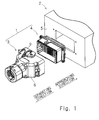
- FIG. 1 shows a state before mating of the lever connector 1.
- the lever connector 1 according to an exemplary embodiment is used as, for example, an interface of an airtight casing 2, such as industrial equipment.
- the lever connector 1 includes a plug 3 (first connector member) and a receptacle 4 (second connector member).
- the casing 2 includes a front panel 5.
- the thickness direction of the front panel 5 is horizontal in this exemplary embodiment.
- the plug 3 is a connector member which is attached to an end of an electric wire bundle that is a bundle of a plurality of electric wires used for power supply and signal communication.
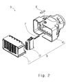
- Fig. 2 is an exploded view of the plug 3.
- the plug 3 includes a plug housing 6, a plurality of plug contacts 7, a temporary holding spring 8 (a temporary holding elastic piece, a temporary holding mechanism), and a lever 9.
- the plug housing 6 includes a plug hood 10 made of an aluminum alloy, a plug barrel 11 made of an insulating resin, and a plurality of plug insulators 12 made of an insulating resin. Each of the plug insulators 12 holds the plurality of plug contacts 7.
- the plug barrel 11 holds the plurality of plug insulators 12.
- the plug barrel 11 is accommodated in the plug hood 10.
- the temporary holding spring 8 is an elastic piece and is attached to the plug hood 10 in a cantilever manner.
- the lever 9 is rotatably attached to the plug housing 6.
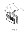
- Fig. 3 is an exploded view of the receptacle 4.
- the receptacle 4 is a connector member that is attached to the front panel 5 of the casing 2 and allows electric wires 13 within the casing 2 to be attached to the receptacle 4.
- the receptacle 4 includes a receptacle housing 14 and a plurality of receptacle contacts 15.
- the receptacle housing 14 includes a receptacle shell 16 made of an aluminum alloy, and a plurality of receptacle insulators 17 made of an insulating resin. Each of the receptacle contacts 15 is attached to an end of the corresponding electric wire 13.
- Each of the receptacle insulators 17 holds the plurality of receptacle contacts 15.
- the receptacle shell 16 holds the plurality of receptacle insulators 17.
- the receptacle shell 16 is formed into a rectangular tubular shape.
- Racks 19 are formed on an outer surface 18 of the receptacle shell 16.
- the lever 9 is rotatably attached to the plug housing 6.
- Fig. 4 shows the lever 9 and a lever rotation axis 9C which is a rotation axis of the lever 9.
- the lever 9 includes two lever opposed portions 20, a lever operating portion 21, and two pinions 22.
- the lever opposed portions 20 are plate bodies which are opposed to each other in the axial direction of the lever rotation axis 9C.
- the thickness direction of each lever opposed portion 20 coincides with the axial direction of the lever rotation axis 9C.
- Each of the pinions 22 is formed on an inner surface 23 of the corresponding lever opposed portion 20 in such a manner that the pinion 22 projects inward.
- the lever operating portion 21 is a portion that couples the two lever opposed portions 20.
- the lever operating portion 21 has a lever lock spring 24 formed thereon.
- the lever lock spring 24 is an elastic piece that is supported by the lever operating portion 21 in a cantilever manner.
- the locking direction is a direction in which the lever 9 is rotated so that the plug 3 and the receptacle 4 are pulled together.
- the unlocking direction is a direction opposite to the locking direction.
- the approaching direction is a direction in which the plug 3 is caused to approach the receptacle 4 in a state where the plug 3 confronts the receptacle 4 so as to mate the plug 3 with the receptacle 4.
- the separating direction is a direction in which the plug 3 is separated from the receptacle 4 in the state shown in Fig. 1 . That is, the approaching direction and the separating direction are opposite directions.
- Fig. 5 is an enlarged view of a portion "A" shown in Fig. 4 .
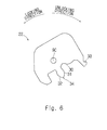
- Fig. 6 illustrates only one of the pinions 22 in a simplified manner.
- the pinion 22 is formed in the vicinity of the lever rotation axis 9C.
- the pinion 22 includes a pinion first driven surface 30 (lever driven surface), a pinion driving surface 31 (lever driving surface), a pinion second driven surface 32, and a pinion temporary holding surface 33.
- the pinion first driven surface 30, the pinion driving surface 31, and the pinion second driven surface 32 are arranged in this order in the unlocking direction.
- the pinion first driven surface 30 is a surface that faces in the unlocking direction.
- the pinion driving surface 31 is a surface that faces in the locking direction and is opposed to the pinion first driven surface 30 in the rotation direction of the lever 9.
- the pinion second driven surface 32 is a surface that faces in the unlocking direction.
- a pinion tooth 34 is formed between the pinion driving surface 31 and the pinion second driven surface 32.
- the pinion driving surface 31 and the pinion second driven surface 32 each correspond to the tooth surface of the pinion tooth 34.
- the pinion temporary holding surface 33 is opposite to the lever rotation axis 9C with the pinion first driven surface 30 interposed therebetween.
- the temporary holding spring 8 includes a fixed portion 40 and an elastic beam 41.
- the fixed portion 40 is fixed to the plug hood 10 (also see Fig. 2 ).
- the elastic beam 41 extends in the approaching direction from the fixed portion 40.
- the elastic beam 41 has a temporary-holding execution surface 42 and a temporary-holding releasing operation surface 43.
- the temporary-holding execution surface 42 is a surface that faces in the approaching direction.
- the temporary-holding releasing operation surface 43 is a surface that faces in the approaching direction and is formed with a slope.
- each plug contact 7 is a socket contact.
- the plug contact 7 includes a socket portion 50 having a cylindrical shape, an open barrel conductor grip 51, an open barrel insulation grip 52, and a contact piece 53 (plug contact portion).
- the contact piece 53 is formed as a part of a peripheral wall of the socket portion 50.
- the contact piece 53 is supported by the socket portion 50 in a cantilever manner.
- a contact point 54 that curves in a convex shape toward the central axis of the socket portion 50 is formed at a tip of the contact piece 53.
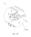
- Fig. 10 is a perspective view showing one of the racks 19.
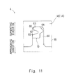
- Fig. 11 illustrates the rack 19 in a simplified manner.
- a rack table 60 is formed on the outer surface 18 of the receptacle shell 16 in such a manner that the rack table 60 projects from the outer surface 18.
- the rack 19 is formed on the rack table 60 in such a manner that the rack 19 projects from the rack table 60.
- the rack 19 includes a rack first driving surface 61 (receptacle driving surface), a rack driven surface 62 (receptacle driven surface), a rack second driving surface 63, and a temporary-holding release execution surface 64.
- the rack first driving surface 61, the rack driven surface 62, and the rack second driving surface 63 are arranged in this order in the approaching direction.
- the rack first driving surface 61 faces in the separating direction and is inclined.
- the rack driven surface 62 faces in the approaching direction and is inclined.
- the rack second driving surface 63 faces in the separating direction and is inclined.
- the rack second driving surface 63 is opposed to the rack driven surface 62 in the movement direction of the plug 3.
- a rack tooth 65 is formed between the rack first driving surface 61 and the rack driven surface 62.
- the rack first driving surface 61 and the rack driven surface 62 each correspond to the tooth surface of the rack tooth 65.
- the temporary-holding release execution surface 64 faces in the separating direction and is inclined.
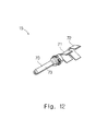
- each receptacle contact 15 is a pin contact.
- the receptacle contact 15 includes a pin portion 70 (receptacle contact portion) having a round bar shape, an open barrel conductor grip 71, and an open barrel insulation grip 72.
- the pin portion 70 has an outer peripheral surface 73.
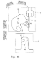
- Fig. 14 illustrates the pinion 22, the rack 19, and the temporary holding spring 8 in a simplified manner in the state shown in Fig. 13 .
- the pinion temporary holding surface 33 of the pinion 22 is opposed to the temporary-holding execution surface 42 of the temporary holding spring 8 in the rotation direction of the lever 9 as shown in Fig. 14 . That is, the pinion temporary holding surface 33 hooks on to the temporary-holding execution surface 42. This inhibits the rotation of the lever 9 in the locking direction in the state shown in Fig. 13 .
- the temporary holding spring 8 temporarily holds the lever 9 at an unlock position.
- the pinion first driven surface 30 of the pinion 22 is opposed to the rack first driving surface 61 of the rack 19 in the approaching direction.
- Fig. 14 shows a clearance D1 (distance) between the pinion first driven surface 30 and the rack first driving surface 61 in the approaching direction.
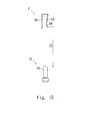
- Fig. 15 illustrates the plug contact 7 and the receptacle contact 15 in a simplified manner in the state shown in Fig. 13 .
- Fig. 15 shows a clearance D2 between the contact point 54 of the contact piece 53 of the plug contact 7 and the pin portion 70 of the receptacle contact 15.
- the relation between the clearance D1 and the clearance D2 is expressed as D1 ⁇ D2.
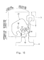
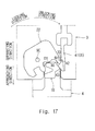
- Figs. 16 to 18 sequentially illustrate the operations of the pinion 22, the rack 19, and the temporary holding spring 8 when the plug 3 is moved toward the receptacle 4 from the state shown in Fig. 13 .
- Fig. 19 shows a state where the lever 9 automatically rotates when the plug 3 is further moved toward the receptacle 4 from the state shown in Fig. 18 .
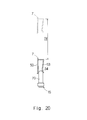
- Fig. 20 illustrates the plug contact 7 and the receptacle contact 15 in a simplified manner in the state shown in Fig. 19 .
- the lever 9 automatically rotates in the locking direction for the following reasons.
- a first reason is that the pinion 22 is rotatable in the locking direction.
- a second reason is that since the pinion first driven surface 30 is in contact with the rack first driving surface 61, the movement of the pinion first driven surface 30 in the approaching direction is restricted, so that a moment about the lever rotation axis 9C acts on the lever 9.
- a third reason is that since there is still a gap between the contact point 54 of the plug contact 7 shown in Fig. 15 and the pin portion 70 of the receptacle contact 15, no resistance force is generated against the movement of the plug 3 toward the receptacle 4.
- the pinion first driven surface 30 is already separated from the rack first driving surface 61, and instead the pinion second driven surface 32 is in contact with the rack second driving surface 63.
- the pinion tooth 34 is inserted between the rack driven surface 62 and the rack second driving surface 63.
- Fig. 22 shows a state where the lever 9 is manually rotated in the locking direction with a finger hooked on the lever operating portion 21 of the lever 9 in the state shown in Fig. 19 .
- Fig. 23 shows the state of the pinion 22 and the rack 19 when the lever 9 is manually rotated.
- the pinion 22 and the rack 19 collaborate with each other and exert a boosting effect specific to the rack-and-pinion mechanism as shown in Fig. 23 .
- the receptacle 4 is strongly pulled toward the plug 3.
- Fig. 24 illustrates the plug contact 7 and the receptacle contact 15 in a simplified manner when the lever 9 is manually rotated in the locking direction.
- the receptacle 4 is strongly pulled toward the plug 3.
- the pin portion 70 of each receptacle contact 15 is inserted into the socket portion 50 of the corresponding plug contact 7 along with the elastic deformation of the contact piece 53 of the plug contact 7, and the contact point 54 is brought into electrical contact with the outer peripheral surface 73 of the pin portion 70.
- the exemplary embodiment described above has the following features.
- a socket contact is used as the plug contact 7 and a pin contact is used as the receptacle contact 15.
- a pin contact may be used as the plug contact 7 and a socket contact may be used as the receptacle contact 15.
Landscapes
- Details Of Connecting Devices For Male And Female Coupling (AREA)
Abstract
Description
- The present invention relates to a lever connector.
- As shown in
Fig. 25 of this application, Japanese Unexamined Patent Application Publication No.2013-4419 lever connector 100 which includes a rack-and-pinion mechanism. In thelever connector 100, shallowly mating ahousing 102 with amating housing 101 enablesrack teeth 106 of arack portion 105 to mesh withpinion teeth 104 of apinion portion 103. - When a
lever 107 is rotated with a finger placed on anoperation portion 108 of thelever 107, the rack-and-pinion mechanism works. As a result, themating housing 101 is pulled toward thehousing 102 with a small operating force. - When the
lever 107 is rotated to a predetermined position, acover 109 also moves to a closed position in accordance with the rotation of thelever 107, so that alock portion 112 is mated with alock hole 111 of alock piece 110. Accordingly, thecover 109 is held at the closed position and thelever 107 is also held at the mating position. - How much it is necessary to operate the
lever 107 is determined by various design parameters, such as a movement necessary for thehousing 102 with respect to themating housing 101 when thehousing 102 is pulled toward themating housing 101, and the magnitude of the boosting effect of the rack-and-pinion mechanism required when thehousing 102 is pulled toward themating housing 101. - However, emphasis has not been placed on reducing a workload on an operator by reducing how much the
lever 107 is operated. - It is an object of the present invention to provide a technique that reduces a workload on an operator during mating of a lever connector.
- An exemplary aspect of the present invention is a lever connector including: a plug including: a plug contact including a plug contact portion; a plug housing that holds the plug contact; and a lever that is rotatably attached to the plug housing; and a receptacle including: a receptacle contact including a receptacle contact portion capable of coming into contact with the plug contact portion; and a receptacle housing that holds the receptacle contact, the plug and the receptacle being pulled together by rotation of the lever in a first rotation direction. The lever has a lever driven surface that faces in a second rotation direction, the second rotation direction being opposite to the first rotation direction. The receptacle housing has a receptacle driving surface that faces in a separating direction, the separating direction being opposite to an approaching direction in which the plug is caused to approach the receptacle so as to mate the plug with the receptacle. In a state where the plug confronts the receptacle so as to mate the plug with the receptacle, a distance between the lever driven surface and the receptacle driving surface is smaller than a distance between the plug contact portion and the receptacle contact portion. When the plug is moved toward the receptacle, the lever driven surface is first brought into contact with the receptacle driving surface, and then the lever rotates in the first rotation direction, and after that, the plug contact portion is brought into contact with the receptacle contact portion.
- According to the present invention, it is possible to reduce a workload on an operator during mating of a lever connector.
- The above and other objects, features and advantages of the present invention will become more fully understood from the detailed description given hereinbelow and the accompanying drawings which are given by way of illustration only, and thus are not to be considered as limiting the present invention.
-
-
Fig. 1 is a perspective view showing a state before mating of a lever connector; -
Fig. 2 is an exploded perspective view of a plug; -
Fig. 3 is an exploded perspective view of a receptacle; -
Fig. 4 is a perspective view of a lever; -
Fig. 5 is an enlarged view showing a portion "A" shown inFig. 4 ; -
Fig. 6 is an elevation view of a pinion; -
Fig. 7 is a perspective view of a temporary holding spring; -
Fig. 8 is an elevation view of the temporary holding spring; -
Fig. 9 is a perspective view of a plug contact; -
Fig. 10 is a perspective view of a rack; -
Fig. 11 is an elevation view of the rack; -
Fig. 12 is a perspective view of a receptacle contact; -
Fig. 13 is an elevation view showing a lever connector in a state where a plug and a receptacle confront each other; -
Fig. 14 is a diagram showing a pinion and a rack in a state where the plug and the receptacle confront each other; -
Fig. 15 is a diagram showing a plug contact and a receptacle contact in a state where the plug and the receptacle confront each other; -
Fig. 16 is a diagram showing a state where the plug is moved toward the receptacle, thereby bringing the temporary holding spring into contact with the rack; -
Fig. 17 is a diagram showing a state where the plug is further moved toward the receptacle from the state shown inFig. 16 , thereby causing the temporary holding spring to be elastically deformed and releasing the temporary holding; -
Fig. 18 is a diagram showing a state where the plug is further moved toward the receptacle from the state shown inFig. 17 , thereby bringing a rack first driving surface into contact with a pinion first driven surface; -
Fig. 19 is a diagram showing a state where the plug is further moved toward the receptacle from the state shown inFig. 18 , thereby causing the lever to automatically rotate by about 30 degrees in a locking direction; -
Fig. 20 is a diagram showing the plug contact and the receptacle contact in the state shown inFig. 19 ; -
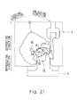
Fig. 21 is a diagram showing the pinion and the rack in the state shown inFig. 19 ; -
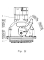
Fig. 22 is an elevation view showing the lever connector in a state where the lever is rotated to a lock position; -
Fig. 23 is a diagram showing the pinion and the rack in the state shown inFig. 22 ; -
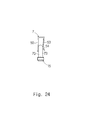
Fig. 24 is a diagram showing the plug contact and the receptacle contact in the state shown inFig. 22 ; and -
Fig. 25 is a diagram corresponding toFig. 1 of Japanese Unexamined Patent Application Publication No.2013-4419 - A
lever connector 1 will be described below with reference toFigs. 1 to 24 .Fig. 1 shows a state before mating of thelever connector 1. As shown inFig. 1 , thelever connector 1 according to an exemplary embodiment is used as, for example, an interface of anairtight casing 2, such as industrial equipment. Thelever connector 1 includes a plug 3 (first connector member) and a receptacle 4 (second connector member). - The
casing 2 includes afront panel 5. The thickness direction of thefront panel 5 is horizontal in this exemplary embodiment. - The
plug 3 is a connector member which is attached to an end of an electric wire bundle that is a bundle of a plurality of electric wires used for power supply and signal communication.Fig. 2 is an exploded view of theplug 3. As shown inFigs. 1 and2 , theplug 3 includes aplug housing 6, a plurality ofplug contacts 7, a temporary holding spring 8 (a temporary holding elastic piece, a temporary holding mechanism), and alever 9. As shown inFig. 2 , theplug housing 6 includes aplug hood 10 made of an aluminum alloy, a plug barrel 11 made of an insulating resin, and a plurality ofplug insulators 12 made of an insulating resin. Each of theplug insulators 12 holds the plurality ofplug contacts 7. The plug barrel 11 holds the plurality ofplug insulators 12. The plug barrel 11 is accommodated in theplug hood 10. Thetemporary holding spring 8 is an elastic piece and is attached to theplug hood 10 in a cantilever manner. As shown inFig. 1 , thelever 9 is rotatably attached to theplug housing 6. -
Fig. 3 is an exploded view of thereceptacle 4. As shown inFigs. 1 and3 , thereceptacle 4 is a connector member that is attached to thefront panel 5 of thecasing 2 and allowselectric wires 13 within thecasing 2 to be attached to thereceptacle 4. As shown inFig. 3 , thereceptacle 4 includes areceptacle housing 14 and a plurality ofreceptacle contacts 15. Thereceptacle housing 14 includes areceptacle shell 16 made of an aluminum alloy, and a plurality ofreceptacle insulators 17 made of an insulating resin. Each of thereceptacle contacts 15 is attached to an end of the correspondingelectric wire 13. Each of thereceptacle insulators 17 holds the plurality ofreceptacle contacts 15. Thereceptacle shell 16 holds the plurality ofreceptacle insulators 17. Thereceptacle shell 16 is formed into a rectangular tubular shape.Racks 19 are formed on anouter surface 18 of thereceptacle shell 16. - As shown in
Fig. 1 , thelever 9 is rotatably attached to theplug housing 6.Fig. 4 shows thelever 9 and alever rotation axis 9C which is a rotation axis of thelever 9. As shown inFig. 4 , thelever 9 includes two lever opposedportions 20, alever operating portion 21, and twopinions 22. The lever opposedportions 20 are plate bodies which are opposed to each other in the axial direction of thelever rotation axis 9C. The thickness direction of each lever opposedportion 20 coincides with the axial direction of thelever rotation axis 9C. Each of thepinions 22 is formed on aninner surface 23 of the corresponding lever opposedportion 20 in such a manner that thepinion 22 projects inward. Thelever operating portion 21 is a portion that couples the two lever opposedportions 20. Thelever operating portion 21 has alever lock spring 24 formed thereon. Thelever lock spring 24 is an elastic piece that is supported by thelever operating portion 21 in a cantilever manner. - In the structure described above, when the
plug 3 shown inFig. 1 is inserted into thereceptacle 4 and thelever 9 shown inFig. 4 is rotated in a locking direction (first rotation direction), theracks 19 shown inFig. 3 and thepinions 22 shown inFig. 4 collaborate with each other as a so-called rack-and-pinion mechanism, with the result that a strong mating force is generated. Accordingly, theplug 3 and thereceptacle 4 are pulled together and then mated together. - The terms "locking direction", "unlocking direction (second rotation direction)", "approaching direction", and "separating direction" will now be defined. As shown in
Fig. 4 , the locking direction is a direction in which thelever 9 is rotated so that theplug 3 and thereceptacle 4 are pulled together. The unlocking direction is a direction opposite to the locking direction. As shown inFig. 1 , the approaching direction is a direction in which theplug 3 is caused to approach thereceptacle 4 in a state where theplug 3 confronts thereceptacle 4 so as to mate theplug 3 with thereceptacle 4. The separating direction is a direction in which theplug 3 is separated from thereceptacle 4 in the state shown inFig. 1 . That is, the approaching direction and the separating direction are opposite directions. - Referring next to
Figs. 5 and6 , thepinions 22 will be described.Fig. 5 is an enlarged view of a portion "A" shown inFig. 4 .Fig. 6 illustrates only one of thepinions 22 in a simplified manner. As shown inFigs. 5 and6 , thepinion 22 is formed in the vicinity of thelever rotation axis 9C. Thepinion 22 includes a pinion first driven surface 30 (lever driven surface), a pinion driving surface 31 (lever driving surface), a pinion second drivensurface 32, and a piniontemporary holding surface 33. The pinion first drivensurface 30, thepinion driving surface 31, and the pinion second drivensurface 32 are arranged in this order in the unlocking direction. The pinion first drivensurface 30 is a surface that faces in the unlocking direction. Thepinion driving surface 31 is a surface that faces in the locking direction and is opposed to the pinion first drivensurface 30 in the rotation direction of thelever 9. The pinion second drivensurface 32 is a surface that faces in the unlocking direction. Apinion tooth 34 is formed between thepinion driving surface 31 and the pinion second drivensurface 32. Thepinion driving surface 31 and the pinion second drivensurface 32 each correspond to the tooth surface of thepinion tooth 34. The piniontemporary holding surface 33 is opposite to thelever rotation axis 9C with the pinion first drivensurface 30 interposed therebetween. - Referring next to
Figs. 7 and8 , thetemporary holding spring 8 will be described. As shown inFigs. 7 and8 , thetemporary holding spring 8 includes a fixedportion 40 and anelastic beam 41. The fixedportion 40 is fixed to the plug hood 10 (also seeFig. 2 ). Theelastic beam 41 extends in the approaching direction from the fixedportion 40. Theelastic beam 41 has a temporary-holdingexecution surface 42 and a temporary-holding releasingoperation surface 43. The temporary-holdingexecution surface 42 is a surface that faces in the approaching direction. The temporary-holding releasingoperation surface 43 is a surface that faces in the approaching direction and is formed with a slope. - Referring next to
Fig. 9 , theplug contacts 7 will be described. As shown inFig. 9 , eachplug contact 7 is a socket contact. Specifically, theplug contact 7 includes asocket portion 50 having a cylindrical shape, an openbarrel conductor grip 51, an openbarrel insulation grip 52, and a contact piece 53 (plug contact portion). Thecontact piece 53 is formed as a part of a peripheral wall of thesocket portion 50. Thecontact piece 53 is supported by thesocket portion 50 in a cantilever manner. Acontact point 54 that curves in a convex shape toward the central axis of thesocket portion 50 is formed at a tip of thecontact piece 53. - Referring next to
Figs. 10 and11 , theracks 19 will be described.Fig. 10 is a perspective view showing one of theracks 19.Fig. 11 illustrates therack 19 in a simplified manner. As shown inFig. 10 , a rack table 60 is formed on theouter surface 18 of thereceptacle shell 16 in such a manner that the rack table 60 projects from theouter surface 18. Therack 19 is formed on the rack table 60 in such a manner that therack 19 projects from the rack table 60. As shown inFigs. 10 and11 , therack 19 includes a rack first driving surface 61 (receptacle driving surface), a rack driven surface 62 (receptacle driven surface), a rack second drivingsurface 63, and a temporary-holdingrelease execution surface 64. The rack first drivingsurface 61, the rack drivensurface 62, and the rack second drivingsurface 63 are arranged in this order in the approaching direction. The rack first drivingsurface 61 faces in the separating direction and is inclined. The rack drivensurface 62 faces in the approaching direction and is inclined. The rack second drivingsurface 63 faces in the separating direction and is inclined. The rack second drivingsurface 63 is opposed to the rack drivensurface 62 in the movement direction of theplug 3. Arack tooth 65 is formed between the rack first drivingsurface 61 and the rack drivensurface 62. The rack first drivingsurface 61 and the rack drivensurface 62 each correspond to the tooth surface of therack tooth 65. The temporary-holdingrelease execution surface 64 faces in the separating direction and is inclined. - Referring next to
Fig. 12 , thereceptacle contacts 15 will be described. As shown inFig. 12 , eachreceptacle contact 15 is a pin contact. Specifically, thereceptacle contact 15 includes a pin portion 70 (receptacle contact portion) having a round bar shape, an openbarrel conductor grip 71, and an openbarrel insulation grip 72. Thepin portion 70 has an outerperipheral surface 73. - Referring next to
Figs. 13 to 24 , the mating operation of thelever connector 1 will be described. - First, as shown in
Fig. 13 , theplug 3 and thereceptacle 4 confront each other with a slight gap therebetween so that theplug 3 and thereceptacle 4 are mated together.Fig. 14 illustrates thepinion 22, therack 19, and thetemporary holding spring 8 in a simplified manner in the state shown inFig. 13 . In the state shown inFig. 13 , the piniontemporary holding surface 33 of thepinion 22 is opposed to the temporary-holdingexecution surface 42 of thetemporary holding spring 8 in the rotation direction of thelever 9 as shown inFig. 14 . That is, the piniontemporary holding surface 33 hooks on to the temporary-holdingexecution surface 42. This inhibits the rotation of thelever 9 in the locking direction in the state shown inFig. 13 . In other words, thetemporary holding spring 8 temporarily holds thelever 9 at an unlock position. Further, as shown inFig. 14 , the pinion first drivensurface 30 of thepinion 22 is opposed to the rack first drivingsurface 61 of therack 19 in the approaching direction.Fig. 14 shows a clearance D1 (distance) between the pinion first drivensurface 30 and the rack first drivingsurface 61 in the approaching direction.Fig. 15 illustrates theplug contact 7 and thereceptacle contact 15 in a simplified manner in the state shown inFig. 13 .Fig. 15 shows a clearance D2 between thecontact point 54 of thecontact piece 53 of theplug contact 7 and thepin portion 70 of thereceptacle contact 15. In this exemplary embodiment, the relation between the clearance D1 and the clearance D2 is expressed as D1<D2. -
Figs. 16 to 18 sequentially illustrate the operations of thepinion 22, therack 19, and thetemporary holding spring 8 when theplug 3 is moved toward thereceptacle 4 from the state shown inFig. 13 . - When the
plug 3 is moved toward thereceptacle 4 from the state shown inFig. 13 , as shown inFig. 16 , the temporary-holdingrelease execution surface 64 of therack 19 is first brought into contact with the temporary-holding releasingoperation surface 43 of thetemporary holding spring 8. In the state shown inFig. 16 , there is still a gap between the pinion first drivensurface 30 of thepinion 22 and the rack first drivingsurface 61 of therack 19. - When the
plug 3 is further moved toward thereceptacle 4, as shown inFig. 17 , the temporary-holding releasingoperation surface 43 is pressed away by the temporary-holdingrelease execution surface 64 along with the elastic deformation of theelastic beam 41 of thetemporary holding spring 8, with the result that the opposing relationship between the temporary-holdingexecution surface 42 and the piniontemporary holding surface 33 in the approaching direction ceases. Accordingly, the temporary holding of thelever 9 by thetemporary holding spring 8 is released, which allows the rotation of thelever 9 in the locking direction. In the state shown inFig. 17 , there is still a gap between the pinion first drivensurface 30 and the rack first drivingsurface 61. - When the
plug 3 is further moved toward thereceptacle 4, as shown inFig. 18 , the pinion first drivensurface 30 and the rack first drivingsurface 61 are brought into contact with each other. The distance of the movement of theplug 3 toward thereceptacle 4 until the pinion first drivensurface 30 is brought into contact with the rack first drivingsurface 61 from the state shown inFig. 14 is equal to the clearance D1 shown inFig. 14 . -
Fig. 19 shows a state where thelever 9 automatically rotates when theplug 3 is further moved toward thereceptacle 4 from the state shown inFig. 18 .Fig. 20 illustrates theplug contact 7 and thereceptacle contact 15 in a simplified manner in the state shown inFig. 19 . When theplug 3 is further moved toward thereceptacle 4 from the state shown inFig. 18 , as shown inFig. 19 , thelever 9 automatically rotates in the locking direction for the following reasons. A first reason is that thepinion 22 is rotatable in the locking direction. A second reason is that since the pinion first drivensurface 30 is in contact with the rack first drivingsurface 61, the movement of the pinion first drivensurface 30 in the approaching direction is restricted, so that a moment about thelever rotation axis 9C acts on thelever 9. A third reason is that since there is still a gap between thecontact point 54 of theplug contact 7 shown inFig. 15 and thepin portion 70 of thereceptacle contact 15, no resistance force is generated against the movement of theplug 3 toward thereceptacle 4. - However, as shown in
Fig. 19 , when thelever 9 is rotated by about 30 degrees, the automatic rotation of thelever 9 suddenly stops, which makes it extremely difficult to further move theplug 3 toward thereceptacle 4 for the following reasons. A first reason is that, as shown inFig. 20 , when thepin portion 70 of eachreceptacle contact 15 is brought into contact with thecontact point 54 of thecontact piece 53 of thecorresponding plug contact 7, a resistance force is generated against the insertion of thepin portion 70 of eachreceptacle contact 15 into thesocket portion 50 of thecorresponding plug contact 7. A second reason is that since thelever connector 1 of this exemplary embodiment is a multi-contact connector including 80 cores, the resistance force is generated at 80 locations in the same manner. In other words, at the time when thelever 9 is rotated by about 30 degrees, an extremely strong resistance force is generated against the movement of theplug 3 toward thereceptacle 4. Note that the distance of the movement of theplug 3 toward thereceptacle 4 until thecontact point 54 of theplug contact 7 is brought into contact with thepin portion 70 of thereceptacle contact 15 from the state shown inFig. 15 is equal to the clearance D2 shown inFig. 15 .Fig. 21 shows the state of thepinion 22 and therack 19 when thelever 9 is rotated by about 30 degrees. As shown inFig. 21 , in the state where thelever 9 is rotated by about 30 degrees, the pinion first drivensurface 30 is already separated from the rack first drivingsurface 61, and instead the pinion second drivensurface 32 is in contact with the rack second drivingsurface 63. Thepinion tooth 34 is inserted between the rack drivensurface 62 and the rack second drivingsurface 63. -
Fig. 22 shows a state where thelever 9 is manually rotated in the locking direction with a finger hooked on thelever operating portion 21 of thelever 9 in the state shown inFig. 19 .Fig. 23 shows the state of thepinion 22 and therack 19 when thelever 9 is manually rotated. As shown inFig. 22 , when thelever 9 is manually rotated in the locking direction, thepinion 22 and therack 19 collaborate with each other and exert a boosting effect specific to the rack-and-pinion mechanism as shown inFig. 23 . As a result, thereceptacle 4 is strongly pulled toward theplug 3. At this time, thepinion 22 and therack 19 operate together in a state where thepinion driving surface 31 of thepinion 22 is constantly in contact with the rack drivensurface 62 of therack 19.Fig. 24 illustrates theplug contact 7 and thereceptacle contact 15 in a simplified manner when thelever 9 is manually rotated in the locking direction. As shown inFig. 24 , when thelever 9 is manually rotated in the locking direction, thereceptacle 4 is strongly pulled toward theplug 3. As a result, thepin portion 70 of eachreceptacle contact 15 is inserted into thesocket portion 50 of thecorresponding plug contact 7 along with the elastic deformation of thecontact piece 53 of theplug contact 7, and thecontact point 54 is brought into electrical contact with the outerperipheral surface 73 of thepin portion 70. - As a result of manually rotating the
lever 9, as shown inFig. 22 , thelever 9 is rotated by about 60 degrees in total from the unlock position shown inFig. 13 . Then, thelever lock spring 24 of thelever 9 shown inFig. 4 hooks on to a lockposition holding projection 80 of theplug 3 shown inFig. 19 , so that thelever 9 is held at a lock position shown inFig. 22 . Thus, the mating operation of thelever connector 1 is completed. - The exemplary embodiment described above has the following features.
- (1) The
lever connector 1 includes theplug 3 and thereceptacle 4. Theplug 3 includes: theplug contacts 7 each including the contact piece 53 (plug contact portion); theplug housing 6 that holds theplug contacts 7; and thelever 9 that is rotatably attached to theplug housing 6. Thereceptacle 4 includes: thereceptacle contacts 15 each including the pin portion 70 (receptacle contact portion) capable of coming into contact with thecontact piece 53; and thereceptacle housing 14 that holds thereceptacle contacts 15. Theplug 3 and thereceptacle 4 are pulled together by the rotation of thelever 9 in the locking direction (first rotation direction). Thelever 9 has the pinion first driven surface 30 (lever driven surface) that faces in the unlocking direction (second rotation direction) that is opposite to the locking direction. Thereceptacle housing 14 has the rack first driving surface 61 (receptacle driving surface) that faces in the separating direction that is opposite to the approaching direction in which theplug 3 is caused to approach thereceptacle 4 so as to mate theplug 3 with thereceptacle 4. In a state where theplug 3 confronts thereceptacle 4 so as to mate theplug 3 with thereceptacle 4, the clearance D1 (distance) between the pinion first drivensurface 30 and the rack first drivingsurface 61 is smaller than the clearance D2 (distance) between thecontact piece 53 and thepin portion 70. When theplug 3 is moved toward thereceptacle 4, the pinion first drivensurface 30 is first brought into contact with the rack first drivingsurface 61, and then thelever 9 is rotated in the locking direction, and after that, thecontact piece 53 is brought into contact with thepin portion 70. According to the above structure, thelever 9 can be automatically rotated in the locking direction only by moving theplug 3 toward thereceptacle 4. Therefore, a workload on an operator during mating of thelever connector 1 can be reduced compared to a case where the operator is involved in the entire process of rotating thelever 9 in the locking direction.
Note that in Japanese Unexamined Patent Application Publication No.2013-4419 Fig. 25 of this application, thelever 107 is structured so as to interlock with thecover 109, and if thelever 107 automatically rotates, thecover 109 also rotates in accordance with the rotation of thelever 107, which may injure the hand of the operator gripping thehousing 102. - (2) The
plug 3 also includes the temporary holding spring 8 (lever temporary holding mechanism) that temporarily holds thelever 9 in such a manner that the pinion first drivensurface 30 and the rack first drivingsurface 61 are opposed to each other in the approaching direction in a state where theplug 3 confronts thereceptacle 4 so as to mate theplug 3 with thereceptacle 4. Thetemporary holding spring 8 is a temporary holding elastic piece that is supported by theplug housing 6 in a cantilever manner. Thetemporary holding spring 8 hooks on to thelever 9, thereby inhibiting the rotation of thelever 9 in the locking direction. When theplug 3 is moved toward thereceptacle 4, thetemporary holding spring 8 is brought into contact with thereceptacle 4 and elastically deformed. The elastic deformation releases the inhibited state of thelever 9. According to the above structure, when theplug 3 confronts thereceptacle 4 so as to mate theplug 3 with thereceptacle 4, there is no need for the operator to correct the position of thelever 9 and place the pinion first drivensurface 30 and the rack first drivingsurface 61 so as to be opposed to each other. Consequently, the workload on the operator can be reduced. - (3) The
lever 9 has the pinion driving surface 31 (lever driving surface) that faces in the locking direction. Thereceptacle housing 14 has the rack driven surface 62 (receptacle driven surface) that faces in the approaching direction. When thelever 9 is rotated in the locking direction in a state where thecontact piece 53 is in contact with thepin portion 70, thepinion driving surface 31 comes into contact with the rack drivensurface 62. According to the above structure, theplug 3 and thereceptacle 4 can be pulled together. - The preferred exemplary embodiment of the present invention described above can be modified as follows.
- In the exemplary embodiment described above, as shown in
Fig. 15 , a socket contact is used as theplug contact 7 and a pin contact is used as thereceptacle contact 15. Alternatively, a pin contact may be used as theplug contact 7 and a socket contact may be used as thereceptacle contact 15. - From the invention thus described, it will be obvious that the embodiments of the invention may be varied in many ways. Such variations are not to be regarded as a departure from the spirit and scope of the invention, and all such modifications as would be obvious to one skilled in the art are intended for inclusion within the scope of the following claims.
Claims (3)
- A lever connector comprising:a plug including:a plug contact including a plug contact portion;a plug housing that holds the plug contact; anda lever that is rotatably attached to the plug housing; anda receptacle including:a receptacle contact including a receptacle contact portion capable of coming into contact with the plug contact portion; anda receptacle housing that holds the receptacle contact,the plug and the receptacle being pulled together by rotation of the lever in a first rotation direction, whereinthe lever has a lever driven surface that faces in a second rotation direction, the second rotation direction being opposite to the first rotation direction,the receptacle housing has a receptacle driving surface that faces in a separating direction, the separating direction being opposite to an approaching direction in which the plug is caused to approach the receptacle so as to mate the plug with the receptacle,in a state where the plug confronts the receptacle so as to mate the plug with the receptacle, a distance between the lever driven surface and the receptacle driving surface is smaller than a distance between the plug contact portion and the receptacle contact portion, andwhen the plug is moved toward the receptacle, the lever driven surface is first brought into contact with the receptacle driving surface, and then the lever rotates in the first rotation direction, and after that, the plug contact portion is brought into contact with the receptacle contact portion.
- The lever connector according to Claim 1, wherein
the plug includes a lever temporary holding mechanism that temporarily holds the lever in such a manner that the lever driven surface and the receptacle driving surface are opposed to each other in the approaching direction in a state where the plug confronts the receptacle so as to mate the plug with the receptacle,
the lever temporary holding mechanism is formed of a temporary holding elastic piece that is supported by the plug housing in a cantilever manner,
the temporary holding elastic piece hooks on to the lever, thereby inhibiting the rotation of the lever in the first rotation direction,
when the plug is moved toward the receptacle, the temporary holding elastic piece is brought into contact with the receptacle and elastically deformed, and
the elastic deformation releases the inhibited state. - The lever connector according to Claim 1 or 2, wherein
the lever has a lever driving surface that faces in the first rotation direction,
the receptacle housing has a receptacle driven surface that faces in the approaching direction, and
when the lever is rotated in the first rotation direction in a state where the plug contact portion is in contact with the receptacle contact portion, the lever driving surface is brought into contact with the receptacle driven surface.
Applications Claiming Priority (1)
| Application Number | Priority Date | Filing Date | Title |
|---|---|---|---|
| JP2014220271A JP6537805B2 (en) | 2014-10-29 | 2014-10-29 | Lever type connector |
Publications (2)
| Publication Number | Publication Date |
|---|---|
| EP3016214A1 true EP3016214A1 (en) | 2016-05-04 |
| EP3016214B1 EP3016214B1 (en) | 2018-06-27 |
Family
ID=54207415
Family Applications (1)
| Application Number | Title | Priority Date | Filing Date |
|---|---|---|---|
| EP15187147.2A Active EP3016214B1 (en) | 2014-10-29 | 2015-09-28 | Lever connector |
Country Status (5)
| Country | Link |
|---|---|
| US (1) | US9564710B2 (en) |
| EP (1) | EP3016214B1 (en) |
| JP (1) | JP6537805B2 (en) |
| CN (1) | CN105576440B (en) |
| TW (1) | TWI597903B (en) |
Cited By (1)
| Publication number | Priority date | Publication date | Assignee | Title |
|---|---|---|---|---|
| WO2019042947A1 (en) * | 2017-08-30 | 2019-03-07 | Te Connectivity Germany Gmbh | Plug connection for automated coupling of at least two electrical conductors |
Families Citing this family (15)
| Publication number | Priority date | Publication date | Assignee | Title |
|---|---|---|---|---|
| DE102016201385B3 (en) * | 2016-01-29 | 2017-07-27 | Robert Bosch Gmbh | Electrical plug connection |
| DE102016201391B3 (en) * | 2016-01-29 | 2017-08-03 | Robert Bosch Gmbh | Electrical plug connection |
| CN106099570B (en) * | 2016-07-29 | 2018-07-10 | 安徽江淮汽车集团股份有限公司 | A kind of automobile inserting components structure |
| DE102016120929B4 (en) * | 2016-11-03 | 2018-10-31 | Harting Electric Gmbh & Co. Kg | Locking clip for a connector housing |
| JP6574453B2 (en) * | 2017-03-29 | 2019-09-11 | 矢崎総業株式会社 | Connector unit |
| CN107221795A (en) * | 2017-06-20 | 2017-09-29 | 珠海格力电器股份有限公司 | Plug and socket assembly and air conditioner |
| JP6879231B2 (en) * | 2018-03-06 | 2021-06-02 | 住友電装株式会社 | connector |
| JP6943917B2 (en) * | 2019-03-29 | 2021-10-06 | 矢崎総業株式会社 | connector |
| CN110247259B (en) | 2019-07-16 | 2021-09-21 | 东莞讯滔电子有限公司 | Pull belt unlocking structure and connector |
| CN110854624B (en) * | 2019-10-23 | 2025-07-11 | 中航光电科技股份有限公司 | A connector having both locking function and unlocking power-assisted separation function |
| CN110829098B (en) * | 2019-11-25 | 2025-10-10 | 中航光电科技股份有限公司 | Socket and header assembly using the socket |
| US12266893B2 (en) * | 2022-04-19 | 2025-04-01 | Dell Products L.P. | Connection assembly for use in an information handling system |
| JP2024086462A (en) | 2022-12-16 | 2024-06-27 | 日本航空電子工業株式会社 | Connector Assembly |
| TWI840206B (en) * | 2023-04-27 | 2024-04-21 | 禾昌興業股份有限公司 | Connector assembly |
| EP4468531A1 (en) * | 2023-05-26 | 2024-11-27 | TE Connectivity India Private Limited | Housing assembly for a connector, connector and connection assembly |
Citations (6)
| Publication number | Priority date | Publication date | Assignee | Title |
|---|---|---|---|---|
| GB2179506A (en) * | 1985-08-03 | 1987-03-04 | Cannon Electric Gmbh | Electrical connector with stirrup lock |
| US5174785A (en) * | 1990-07-17 | 1992-12-29 | Yazaki Corporation | Low insertion-withdrawal force electric connector |
| GB2289171A (en) * | 1991-10-21 | 1995-11-08 | Sumitomo Wall Systems Ltd | Stirrup lever connector |
| US5603624A (en) * | 1993-12-20 | 1997-02-18 | Yazki Corporation | Connector with fitting operation lever |
| WO2006020924A2 (en) * | 2004-08-13 | 2006-02-23 | Jst Corporation | Lever action mechanical assist connector |
| JP2013004419A (en) | 2011-06-20 | 2013-01-07 | Sumitomo Wiring Syst Ltd | Lever type connector |
Family Cites Families (25)
| Publication number | Priority date | Publication date | Assignee | Title |
|---|---|---|---|---|
| JP2705038B2 (en) * | 1990-07-17 | 1998-01-26 | 矢崎総業株式会社 | Low insertion / extraction force electrical connector |
| US5230635A (en) * | 1991-06-25 | 1993-07-27 | Yazaki Corporation | Connector with lever |
| GB9203346D0 (en) * | 1992-02-17 | 1992-04-01 | Amp Gmbh | Electrical connector assembly |
| JP3278048B2 (en) * | 1997-10-01 | 2002-04-30 | 住友電装株式会社 | connector |
| JP3846199B2 (en) * | 2000-05-24 | 2006-11-15 | 治夫 杉山 | Test method for WT1-related diseases |
| US6666698B2 (en) * | 2000-08-17 | 2003-12-23 | Tyco Electronics Corporation | Arc limiting electrical connector assembly |
| JP2002270286A (en) * | 2001-03-13 | 2002-09-20 | Tyco Electronics Amp Kk | Lever driven connector assembly |
| ITTO20010290A1 (en) * | 2001-03-27 | 2002-09-27 | Framatome Connectors Italia | ELECTRIC CONNECTOR. |
| JP3991670B2 (en) * | 2001-12-06 | 2007-10-17 | 住友電装株式会社 | connector |
| JP3987736B2 (en) * | 2002-02-26 | 2007-10-10 | 住友電装株式会社 | Lever type connector |
| JP2006147492A (en) * | 2004-11-24 | 2006-06-08 | Sumitomo Wiring Syst Ltd | Connector |
| JP4317973B2 (en) * | 2004-12-14 | 2009-08-19 | 住友電装株式会社 | connector |
| US7261575B2 (en) * | 2005-03-09 | 2007-08-28 | Tyco Electronics Corporation | Electrical connector and electrical connector assembly having selectively includable lever assist |
| JP4678333B2 (en) * | 2005-09-29 | 2011-04-27 | 住友電装株式会社 | Lever type connector |
| JP4857048B2 (en) * | 2006-08-07 | 2012-01-18 | 日本航空電子工業株式会社 | Lever type connector |
| JP4966622B2 (en) * | 2006-10-12 | 2012-07-04 | 矢崎総業株式会社 | Lever type connector |
| JP4282088B2 (en) * | 2007-02-19 | 2009-06-17 | 日本航空電子工業株式会社 | Connector assembly |
| JP2009259683A (en) * | 2008-04-18 | 2009-11-05 | Sumitomo Wiring Syst Ltd | Lever-type connector |
| US20090305536A1 (en) * | 2008-06-06 | 2009-12-10 | Tyco Electronics Corporation | Electrical connector having a lever assist mating mechanism |
| JP5347936B2 (en) * | 2009-12-10 | 2013-11-20 | 住友電装株式会社 | Lever type connector |
| JP5419224B2 (en) * | 2010-04-13 | 2014-02-19 | 日立金属株式会社 | Lever type connector |
| JP5707166B2 (en) * | 2010-11-09 | 2015-04-22 | 矢崎総業株式会社 | Power circuit breaker |
| CN102801048B (en) * | 2011-05-26 | 2014-10-01 | 日本航空电子工业株式会社 | Connector |
| JP5858745B2 (en) * | 2011-11-21 | 2016-02-10 | 矢崎総業株式会社 | Power circuit breaker |
| JP5949577B2 (en) * | 2013-01-23 | 2016-07-06 | 住友電装株式会社 | Lever type connector |
-
2014
- 2014-10-29 JP JP2014220271A patent/JP6537805B2/en active Active
-
2015
- 2015-09-17 US US14/856,817 patent/US9564710B2/en active Active
- 2015-09-17 CN CN201510595269.3A patent/CN105576440B/en active Active
- 2015-09-23 TW TW104131414A patent/TWI597903B/en active
- 2015-09-28 EP EP15187147.2A patent/EP3016214B1/en active Active
Patent Citations (6)
| Publication number | Priority date | Publication date | Assignee | Title |
|---|---|---|---|---|
| GB2179506A (en) * | 1985-08-03 | 1987-03-04 | Cannon Electric Gmbh | Electrical connector with stirrup lock |
| US5174785A (en) * | 1990-07-17 | 1992-12-29 | Yazaki Corporation | Low insertion-withdrawal force electric connector |
| GB2289171A (en) * | 1991-10-21 | 1995-11-08 | Sumitomo Wall Systems Ltd | Stirrup lever connector |
| US5603624A (en) * | 1993-12-20 | 1997-02-18 | Yazki Corporation | Connector with fitting operation lever |
| WO2006020924A2 (en) * | 2004-08-13 | 2006-02-23 | Jst Corporation | Lever action mechanical assist connector |
| JP2013004419A (en) | 2011-06-20 | 2013-01-07 | Sumitomo Wiring Syst Ltd | Lever type connector |
Cited By (4)
| Publication number | Priority date | Publication date | Assignee | Title |
|---|---|---|---|---|
| WO2019042947A1 (en) * | 2017-08-30 | 2019-03-07 | Te Connectivity Germany Gmbh | Plug connection for automated coupling of at least two electrical conductors |
| CN111052515A (en) * | 2017-08-30 | 2020-04-21 | 泰连德国有限公司 | Plug connection device for automatic coupling of at least two electrical conductors |
| CN111052515B (en) * | 2017-08-30 | 2021-09-14 | 泰连德国有限公司 | Plug connection for the automatic connection of at least two electrical conductors |
| US11228142B2 (en) | 2017-08-30 | 2022-01-18 | Te Connectivity Germany Gmbh | Plug connection for automated coupling of at least two electrical conductors |
Also Published As
| Publication number | Publication date |
|---|---|
| US9564710B2 (en) | 2017-02-07 |
| JP6537805B2 (en) | 2019-07-03 |
| TW201616740A (en) | 2016-05-01 |
| CN105576440B (en) | 2018-12-18 |
| CN105576440A (en) | 2016-05-11 |
| JP2016091594A (en) | 2016-05-23 |
| TWI597903B (en) | 2017-09-01 |
| US20160126671A1 (en) | 2016-05-05 |
| EP3016214B1 (en) | 2018-06-27 |
Similar Documents
| Publication | Publication Date | Title |
|---|---|---|
| EP3016214B1 (en) | Lever connector | |
| JP4867875B2 (en) | Lever type connector | |
| JP6099203B2 (en) | Connector device | |
| EP2284960A1 (en) | Lever-type connector | |
| US10211570B2 (en) | Lever-fitting type connector | |
| JP7460397B2 (en) | High voltage electrical connector with CPA assembled on slider | |
| EP3637558A1 (en) | Connector | |
| JP6580629B2 (en) | Service plug | |
| US9373913B2 (en) | Lever type connector | |
| JP6397996B2 (en) | Connector with latch | |
| JP5856869B2 (en) | Lever assembly device for connector with lever | |
| JP5151726B2 (en) | Connector and electronic device system | |
| JP4679385B2 (en) | Lever fitting type connector | |
| CN108695648B (en) | Connector with a locking member | |
| WO2017082228A1 (en) | Connector device | |
| WO2016060131A1 (en) | Connector | |
| JP6465334B2 (en) | Electrical connector | |
| US20090258525A1 (en) | Connector With Improved Latching Mechanism | |
| CN113555730B (en) | Lever type connector | |
| CN106025694B (en) | Electric connector system with laterally projecting release arm | |
| JP2020042992A (en) | Coaxial connector with lock function, coaxial connector device including the coaxial connector, and lock member used for the coaxial connector and the like | |
| JP2017073284A (en) | Connector for cable connection | |
| JP2013258087A (en) | Quick connection terminal device | |
| JP2015183416A (en) | electric lock system | |
| JP2015141745A (en) | terminal insertion jig |
Legal Events
| Date | Code | Title | Description |
|---|---|---|---|
| PUAI | Public reference made under article 153(3) epc to a published international application that has entered the european phase |
Free format text: ORIGINAL CODE: 0009012 |
|
| 17P | Request for examination filed |
Effective date: 20150928 |
|
| AK | Designated contracting states |
Kind code of ref document: A1 Designated state(s): AL AT BE BG CH CY CZ DE DK EE ES FI FR GB GR HR HU IE IS IT LI LT LU LV MC MK MT NL NO PL PT RO RS SE SI SK SM TR |
|
| AX | Request for extension of the european patent |
Extension state: BA ME |
|
| 17Q | First examination report despatched |
Effective date: 20170220 |
|
| GRAP | Despatch of communication of intention to grant a patent |
Free format text: ORIGINAL CODE: EPIDOSNIGR1 |
|
| RIC1 | Information provided on ipc code assigned before grant |
Ipc: H01R 13/629 20060101AFI20180103BHEP Ipc: H01R 107/00 20060101ALN20180103BHEP |
|
| INTG | Intention to grant announced |
Effective date: 20180123 |
|
| RIN1 | Information on inventor provided before grant (corrected) |
Inventor name: EBIHARA, HIROYUKI |
|
| GRAS | Grant fee paid |
Free format text: ORIGINAL CODE: EPIDOSNIGR3 |
|
| GRAA | (expected) grant |
Free format text: ORIGINAL CODE: 0009210 |
|
| AK | Designated contracting states |
Kind code of ref document: B1 Designated state(s): AL AT BE BG CH CY CZ DE DK EE ES FI FR GB GR HR HU IE IS IT LI LT LU LV MC MK MT NL NO PL PT RO RS SE SI SK SM TR |
|
| REG | Reference to a national code |
Ref country code: GB Ref legal event code: FG4D |
|
| REG | Reference to a national code |
Ref country code: AT Ref legal event code: REF Ref document number: 1013121 Country of ref document: AT Kind code of ref document: T Effective date: 20180715 |
|
| REG | Reference to a national code |
Ref country code: IE Ref legal event code: FG4D |
|
| REG | Reference to a national code |
Ref country code: DE Ref legal event code: R096 Ref document number: 602015012661 Country of ref document: DE |
|
| PG25 | Lapsed in a contracting state [announced via postgrant information from national office to epo] |
Ref country code: SE Free format text: LAPSE BECAUSE OF FAILURE TO SUBMIT A TRANSLATION OF THE DESCRIPTION OR TO PAY THE FEE WITHIN THE PRESCRIBED TIME-LIMIT Effective date: 20180627 Ref country code: LT Free format text: LAPSE BECAUSE OF FAILURE TO SUBMIT A TRANSLATION OF THE DESCRIPTION OR TO PAY THE FEE WITHIN THE PRESCRIBED TIME-LIMIT Effective date: 20180627 Ref country code: NO Free format text: LAPSE BECAUSE OF FAILURE TO SUBMIT A TRANSLATION OF THE DESCRIPTION OR TO PAY THE FEE WITHIN THE PRESCRIBED TIME-LIMIT Effective date: 20180927 Ref country code: BG Free format text: LAPSE BECAUSE OF FAILURE TO SUBMIT A TRANSLATION OF THE DESCRIPTION OR TO PAY THE FEE WITHIN THE PRESCRIBED TIME-LIMIT Effective date: 20180927 Ref country code: FI Free format text: LAPSE BECAUSE OF FAILURE TO SUBMIT A TRANSLATION OF THE DESCRIPTION OR TO PAY THE FEE WITHIN THE PRESCRIBED TIME-LIMIT Effective date: 20180627 |
|
| REG | Reference to a national code |
Ref country code: NL Ref legal event code: MP Effective date: 20180627 |
|
| REG | Reference to a national code |
Ref country code: LT Ref legal event code: MG4D |
|
| PG25 | Lapsed in a contracting state [announced via postgrant information from national office to epo] |
Ref country code: RS Free format text: LAPSE BECAUSE OF FAILURE TO SUBMIT A TRANSLATION OF THE DESCRIPTION OR TO PAY THE FEE WITHIN THE PRESCRIBED TIME-LIMIT Effective date: 20180627 Ref country code: HR Free format text: LAPSE BECAUSE OF FAILURE TO SUBMIT A TRANSLATION OF THE DESCRIPTION OR TO PAY THE FEE WITHIN THE PRESCRIBED TIME-LIMIT Effective date: 20180627 Ref country code: GR Free format text: LAPSE BECAUSE OF FAILURE TO SUBMIT A TRANSLATION OF THE DESCRIPTION OR TO PAY THE FEE WITHIN THE PRESCRIBED TIME-LIMIT Effective date: 20180928 Ref country code: LV Free format text: LAPSE BECAUSE OF FAILURE TO SUBMIT A TRANSLATION OF THE DESCRIPTION OR TO PAY THE FEE WITHIN THE PRESCRIBED TIME-LIMIT Effective date: 20180627 |
|
| REG | Reference to a national code |
Ref country code: AT Ref legal event code: MK05 Ref document number: 1013121 Country of ref document: AT Kind code of ref document: T Effective date: 20180627 |
|
| PG25 | Lapsed in a contracting state [announced via postgrant information from national office to epo] |
Ref country code: NL Free format text: LAPSE BECAUSE OF FAILURE TO SUBMIT A TRANSLATION OF THE DESCRIPTION OR TO PAY THE FEE WITHIN THE PRESCRIBED TIME-LIMIT Effective date: 20180627 |
|
| PG25 | Lapsed in a contracting state [announced via postgrant information from national office to epo] |
Ref country code: AT Free format text: LAPSE BECAUSE OF FAILURE TO SUBMIT A TRANSLATION OF THE DESCRIPTION OR TO PAY THE FEE WITHIN THE PRESCRIBED TIME-LIMIT Effective date: 20180627 Ref country code: EE Free format text: LAPSE BECAUSE OF FAILURE TO SUBMIT A TRANSLATION OF THE DESCRIPTION OR TO PAY THE FEE WITHIN THE PRESCRIBED TIME-LIMIT Effective date: 20180627 Ref country code: IS Free format text: LAPSE BECAUSE OF FAILURE TO SUBMIT A TRANSLATION OF THE DESCRIPTION OR TO PAY THE FEE WITHIN THE PRESCRIBED TIME-LIMIT Effective date: 20181027 Ref country code: SK Free format text: LAPSE BECAUSE OF FAILURE TO SUBMIT A TRANSLATION OF THE DESCRIPTION OR TO PAY THE FEE WITHIN THE PRESCRIBED TIME-LIMIT Effective date: 20180627 Ref country code: RO Free format text: LAPSE BECAUSE OF FAILURE TO SUBMIT A TRANSLATION OF THE DESCRIPTION OR TO PAY THE FEE WITHIN THE PRESCRIBED TIME-LIMIT Effective date: 20180627 Ref country code: CZ Free format text: LAPSE BECAUSE OF FAILURE TO SUBMIT A TRANSLATION OF THE DESCRIPTION OR TO PAY THE FEE WITHIN THE PRESCRIBED TIME-LIMIT Effective date: 20180627 Ref country code: PL Free format text: LAPSE BECAUSE OF FAILURE TO SUBMIT A TRANSLATION OF THE DESCRIPTION OR TO PAY THE FEE WITHIN THE PRESCRIBED TIME-LIMIT Effective date: 20180627 |
|
| PG25 | Lapsed in a contracting state [announced via postgrant information from national office to epo] |
Ref country code: IT Free format text: LAPSE BECAUSE OF FAILURE TO SUBMIT A TRANSLATION OF THE DESCRIPTION OR TO PAY THE FEE WITHIN THE PRESCRIBED TIME-LIMIT Effective date: 20180627 Ref country code: SM Free format text: LAPSE BECAUSE OF FAILURE TO SUBMIT A TRANSLATION OF THE DESCRIPTION OR TO PAY THE FEE WITHIN THE PRESCRIBED TIME-LIMIT Effective date: 20180627 Ref country code: ES Free format text: LAPSE BECAUSE OF FAILURE TO SUBMIT A TRANSLATION OF THE DESCRIPTION OR TO PAY THE FEE WITHIN THE PRESCRIBED TIME-LIMIT Effective date: 20180627 |
|
| REG | Reference to a national code |
Ref country code: DE Ref legal event code: R097 Ref document number: 602015012661 Country of ref document: DE |
|
| PG25 | Lapsed in a contracting state [announced via postgrant information from national office to epo] |
Ref country code: MC Free format text: LAPSE BECAUSE OF FAILURE TO SUBMIT A TRANSLATION OF THE DESCRIPTION OR TO PAY THE FEE WITHIN THE PRESCRIBED TIME-LIMIT Effective date: 20180627 |
|
| REG | Reference to a national code |
Ref country code: CH Ref legal event code: PL |
|
| PLBE | No opposition filed within time limit |
Free format text: ORIGINAL CODE: 0009261 |
|
| STAA | Information on the status of an ep patent application or granted ep patent |
Free format text: STATUS: NO OPPOSITION FILED WITHIN TIME LIMIT |
|
| PG25 | Lapsed in a contracting state [announced via postgrant information from national office to epo] |
Ref country code: DK Free format text: LAPSE BECAUSE OF FAILURE TO SUBMIT A TRANSLATION OF THE DESCRIPTION OR TO PAY THE FEE WITHIN THE PRESCRIBED TIME-LIMIT Effective date: 20180627 |
|
| 26N | No opposition filed |
Effective date: 20190328 |
|
| REG | Reference to a national code |
Ref country code: BE Ref legal event code: MM Effective date: 20180930 |
|
| REG | Reference to a national code |
Ref country code: IE Ref legal event code: MM4A |
|
| PG25 | Lapsed in a contracting state [announced via postgrant information from national office to epo] |
Ref country code: LU Free format text: LAPSE BECAUSE OF NON-PAYMENT OF DUE FEES Effective date: 20180928 |
|
| PG25 | Lapsed in a contracting state [announced via postgrant information from national office to epo] |
Ref country code: IE Free format text: LAPSE BECAUSE OF NON-PAYMENT OF DUE FEES Effective date: 20180928 |
|
| PG25 | Lapsed in a contracting state [announced via postgrant information from national office to epo] |
Ref country code: SI Free format text: LAPSE BECAUSE OF FAILURE TO SUBMIT A TRANSLATION OF THE DESCRIPTION OR TO PAY THE FEE WITHIN THE PRESCRIBED TIME-LIMIT Effective date: 20180627 Ref country code: CH Free format text: LAPSE BECAUSE OF NON-PAYMENT OF DUE FEES Effective date: 20180930 Ref country code: LI Free format text: LAPSE BECAUSE OF NON-PAYMENT OF DUE FEES Effective date: 20180930 Ref country code: FR Free format text: LAPSE BECAUSE OF NON-PAYMENT OF DUE FEES Effective date: 20180930 Ref country code: BE Free format text: LAPSE BECAUSE OF NON-PAYMENT OF DUE FEES Effective date: 20180930 |
|
| PG25 | Lapsed in a contracting state [announced via postgrant information from national office to epo] |
Ref country code: AL Free format text: LAPSE BECAUSE OF FAILURE TO SUBMIT A TRANSLATION OF THE DESCRIPTION OR TO PAY THE FEE WITHIN THE PRESCRIBED TIME-LIMIT Effective date: 20180627 |
|
| PG25 | Lapsed in a contracting state [announced via postgrant information from national office to epo] |
Ref country code: MT Free format text: LAPSE BECAUSE OF NON-PAYMENT OF DUE FEES Effective date: 20180928 |
|
| PG25 | Lapsed in a contracting state [announced via postgrant information from national office to epo] |
Ref country code: TR Free format text: LAPSE BECAUSE OF FAILURE TO SUBMIT A TRANSLATION OF THE DESCRIPTION OR TO PAY THE FEE WITHIN THE PRESCRIBED TIME-LIMIT Effective date: 20180627 |
|
| PG25 | Lapsed in a contracting state [announced via postgrant information from national office to epo] |
Ref country code: PT Free format text: LAPSE BECAUSE OF FAILURE TO SUBMIT A TRANSLATION OF THE DESCRIPTION OR TO PAY THE FEE WITHIN THE PRESCRIBED TIME-LIMIT Effective date: 20180627 |
|
| PG25 | Lapsed in a contracting state [announced via postgrant information from national office to epo] |
Ref country code: CY Free format text: LAPSE BECAUSE OF FAILURE TO SUBMIT A TRANSLATION OF THE DESCRIPTION OR TO PAY THE FEE WITHIN THE PRESCRIBED TIME-LIMIT Effective date: 20180627 Ref country code: HU Free format text: LAPSE BECAUSE OF FAILURE TO SUBMIT A TRANSLATION OF THE DESCRIPTION OR TO PAY THE FEE WITHIN THE PRESCRIBED TIME-LIMIT; INVALID AB INITIO Effective date: 20150928 Ref country code: MK Free format text: LAPSE BECAUSE OF NON-PAYMENT OF DUE FEES Effective date: 20180627 |
|
| GBPC | Gb: european patent ceased through non-payment of renewal fee |
Effective date: 20190928 |
|
| PG25 | Lapsed in a contracting state [announced via postgrant information from national office to epo] |
Ref country code: GB Free format text: LAPSE BECAUSE OF NON-PAYMENT OF DUE FEES Effective date: 20190928 |
|
| PGFP | Annual fee paid to national office [announced via postgrant information from national office to epo] |
Ref country code: DE Payment date: 20250805 Year of fee payment: 11 |