EP3016126A1 - Magnetically driven trip mechanism for an overload relay - Google Patents
Magnetically driven trip mechanism for an overload relay Download PDFInfo
- Publication number
- EP3016126A1 EP3016126A1 EP15186544.1A EP15186544A EP3016126A1 EP 3016126 A1 EP3016126 A1 EP 3016126A1 EP 15186544 A EP15186544 A EP 15186544A EP 3016126 A1 EP3016126 A1 EP 3016126A1
- Authority
- EP
- European Patent Office
- Prior art keywords
- tripping
- moveable
- permanent magnet
- electrical contact
- contact carrier
- Prior art date
- Legal status (The legal status is an assumption and is not a legal conclusion. Google has not performed a legal analysis and makes no representation as to the accuracy of the status listed.)
- Granted
Links
Images


Classifications
-
- H—ELECTRICITY
- H01—ELECTRIC ELEMENTS
- H01H—ELECTRIC SWITCHES; RELAYS; SELECTORS; EMERGENCY PROTECTIVE DEVICES
- H01H36/00—Switches actuated by change of magnetic field or of electric field, e.g. by change of relative position of magnet and switch, by shielding
- H01H36/0073—Switches actuated by change of magnetic field or of electric field, e.g. by change of relative position of magnet and switch, by shielding actuated by relative movement between two magnets
-
- H—ELECTRICITY
- H01—ELECTRIC ELEMENTS
- H01H—ELECTRIC SWITCHES; RELAYS; SELECTORS; EMERGENCY PROTECTIVE DEVICES
- H01H71/00—Details of the protective switches or relays covered by groups H01H73/00 - H01H83/00
- H01H71/10—Operating or release mechanisms
- H01H71/12—Automatic release mechanisms with or without manual release
- H01H71/24—Electromagnetic mechanisms
- H01H71/32—Electromagnetic mechanisms having permanently magnetised part
-
- H—ELECTRICITY
- H01—ELECTRIC ELEMENTS
- H01H—ELECTRIC SWITCHES; RELAYS; SELECTORS; EMERGENCY PROTECTIVE DEVICES
- H01H37/00—Thermally-actuated switches
- H01H37/02—Details
- H01H37/32—Thermally-sensitive members
- H01H37/52—Thermally-sensitive members actuated due to deflection of bimetallic element
-
- H—ELECTRICITY
- H01—ELECTRIC ELEMENTS
- H01H—ELECTRIC SWITCHES; RELAYS; SELECTORS; EMERGENCY PROTECTIVE DEVICES
- H01H51/00—Electromagnetic relays
- H01H51/22—Polarised relays
- H01H51/2209—Polarised relays with rectilinearly movable armature
- H01H2051/2218—Polarised relays with rectilinearly movable armature having at least one movable permanent magnet
-
- H—ELECTRICITY
- H01—ELECTRIC ELEMENTS
- H01H—ELECTRIC SWITCHES; RELAYS; SELECTORS; EMERGENCY PROTECTIVE DEVICES
- H01H61/00—Electrothermal relays
- H01H61/02—Electrothermal relays wherein the thermally-sensitive member is heated indirectly, e.g. resistively, inductively
-
- H—ELECTRICITY
- H01—ELECTRIC ELEMENTS
- H01H—ELECTRIC SWITCHES; RELAYS; SELECTORS; EMERGENCY PROTECTIVE DEVICES
- H01H71/00—Details of the protective switches or relays covered by groups H01H73/00 - H01H83/00
- H01H71/10—Operating or release mechanisms
- H01H71/12—Automatic release mechanisms with or without manual release
- H01H71/14—Electrothermal mechanisms
- H01H71/16—Electrothermal mechanisms with bimetal element
-
- H—ELECTRICITY
- H01—ELECTRIC ELEMENTS
- H01H—ELECTRIC SWITCHES; RELAYS; SELECTORS; EMERGENCY PROTECTIVE DEVICES
- H01H71/00—Details of the protective switches or relays covered by groups H01H73/00 - H01H83/00
- H01H71/10—Operating or release mechanisms
- H01H71/12—Automatic release mechanisms with or without manual release
- H01H71/14—Electrothermal mechanisms
- H01H71/16—Electrothermal mechanisms with bimetal element
- H01H71/164—Heating elements
-
- H—ELECTRICITY
- H01—ELECTRIC ELEMENTS
- H01H—ELECTRIC SWITCHES; RELAYS; SELECTORS; EMERGENCY PROTECTIVE DEVICES
- H01H71/00—Details of the protective switches or relays covered by groups H01H73/00 - H01H83/00
- H01H71/10—Operating or release mechanisms
- H01H71/12—Automatic release mechanisms with or without manual release
- H01H71/24—Electromagnetic mechanisms
- H01H71/32—Electromagnetic mechanisms having permanently magnetised part
- H01H71/321—Electromagnetic mechanisms having permanently magnetised part characterised by the magnetic circuit or active magnetic elements
- H01H71/323—Electromagnetic mechanisms having permanently magnetised part characterised by the magnetic circuit or active magnetic elements with rotatable armature
Definitions
- the invention disclosed relates to trip mechanism for overload relays.
- Overload relays are intended to protect motors conductors against excessive heating due to prolonged motor overcurrents up to and including locked rotor currents. Overload relays are distinguished from circuit breakers, in that circuit breakers typically protect other types of branch-circuit components from higher currents acting over a shorter interval, due to short circuits or grounds.
- Thermal overload relays sense prolonged motor overcurrent by converting this current to heat in a resistance element. The heat generated is used to open a normally closed contact in series with a starter coil causing the motor to be disconnected from the line.
- overload relays there are three types of overload relays, the melting alloy thermal overload relay, the bimetallic thermal overload relay, and the solid state overload relay.
- the motor current passes through a small heater winding. Under overload conditions, the heat causes a special solder to melt, tripping the relay and opening the normally closed contact in series with a starter coil causing the motor to be disconnected from the line.
- Bimetallic thermal overload relays employ a bimetal strip associated with a current carrying heater coil. When an overload occurs, the heat will cause the bi-metal to deflect and trip the relay, opening the normally closed contact in series with a starter coil causing the motor to be disconnected from the line.
- Solid state electronic overload relays do not require thermal units, instead use current transformers that respond directly to the motor current. Once an overload condition is reached, the electronic circuit of the overload relay trips, causing the contacts to open in a manner similar to the bimetallic thermal overload relay, opening the normally closed contact in series with a starter coil causing the motor to be disconnected from the line.
- the normally closed contact in existing overload relays is typically driven by a mechanical bi-stable spring that is tripped by a complex sequence of levers that are difficult to manufacture because of the tolerances they require.
- Spring actuated bi-stable mechanisms can be difficult to dimension correctly making it difficult to guaranty consistent tripping positions and contact forces. What is needed is a simplified overload tripping mechanism the replaces the mechanical bi-stable spring with a mechanism that does not require difficult manufacturing steps.
- the subject invention provides a simplified overload tripping mechanism for an overload relay, by replacing the mechanical bi-stable spring with two opposing magnets.
- the magnetically driven trip mechanism is relatively easy to manufacture and provides consistent tripping positions and contact forces in an overload relay.
- the invention comprises a tripping actuator having a first permanent magnet and a moveable contact carrier having a second permanent magnet mounted in an opposed orientation to the first permanent magnet.
- a moveable electrical contact on the moveable contact carrier is urged, by repulsion between the magnets, to make electrical connection with a stationary electrical contact, when the tripping actuator is in an ON position and the moveable contact carrier in a first stable position.
- the overload relay may use an overcurrent sensing mechanism, such as a bimetallic thermal overload sensor that employs a bimetal strip associated with a current carrying heater coil.
- the heater coil may be connected in series with a power source and a motor.
- the bimetal strip is configured to deflect from heat produced by the heater coil when an overcurrent condition occurs.
- the bimetal strip is connected to the tripping actuator and when an overcurrent condition is sensed, it moves the tripping actuator.
- the first permanent magnet passes the second permanent magnet in a first direction through an over-center tripping position.
- the proximity of the first and second permanent magnets causes them to repel each other and urge the moveable contact carrier and its moveable contact toward a second stable position, moving away from the stationary contact in an opposite, second direction, to break the normally closed electrical connection with the stationary electrical contact.
- the opposing magnets provide the over-center trip function and apply the proper force to open the contacts.
- the invention may include an auto-reset mode to automatically restore the normally closed electrical connection with the stationary electrical contact, after an interval has passed since the overcurrent condition has subsided.
- the bimetal strip When the overcurrent condition subsides and the heater coil cools, the bimetal strip is configured to reverse its deflection, thereby moving the tripping actuator in the second direction, back through the over-center tripping position.
- the first and second magnets repel each other, to thereby urge the moveable contact carrier and its moveable contact to return toward the first stable position, to make the normally closed electrical connection with the stationary electrical contact.
- the contact carrier In the auto-reset mode, the contact carrier is blocked in a position so that it cannot move to the full off position, so that when the tripping actuator returns, it can cause the reset automatically. Without the contact carrier blocked, it moves to a position where the tripping actuator cannot move far enough to cause auto reset and a reset button may then be used
- the invention may include an adjustable mount supporting the first magnet, to enable changing the location of the over-center tripping position by adjusting the orientation of the magnet, to thereby change the set point and sensitivity of the mechanism.
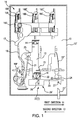
- Figure 1 shows a magnetically driven trip mechanism for an overload relay in a normally closed or ON state.
- the overload relay may be contained in a housing 10'.
- the overload relay may use an overcurrent sensing mechanism, such as a bimetallic thermal overload sensor 16 that employs a bimetal strip 16A associated with a current carrying heater coil 16A'.
- the heater coil may be connected in series with one phase of a power source and a motor.
- the bimetallic thermal overload sensor 16 shown in the figure employs three bimetal strips 16A, 16B and 16C, one for each phase of a three phase power system. Each bimetal strip 16A, 16B and 16C is associated with a respective heater 16A', 16B' and 16C'.
- Each bimetal strip for example 16A, is configured to deflect from heat produced by its heater coil 16A' when an overcurrent condition occurs in that phase.
- any one of the three bimetal strips 16A, 16B and 16C heats due to overcurrent, it bends to the right in the figure, pulling the displacement bar 16D and lever 17 with it.
- the displacement bar 16D and lever 17 push on the bimetal compensation lever assembly 19 and 21, causing it to rotate clockwise about a pivot 19P.
- lever 21 pushes on the bimetal compensation subassembly link or interface 25, referred to herein by the shorter expression "bimetal interface" 25, of the tripping actuator 12.
- bimetal interface 25 moves the tripping actuator 12.
- the tripping actuator 12 is mechanically coupled in this manner to the bimetallic thermal overload sensor 16.
- the tripping actuator 12 has a pivoted end mounted on a pivot 14 on a base 10 in the housing 10'.
- the tripping actuator 12 is shown in Figure 1 , resting in an ON position 15 while there is no overcurrent condition being sensed by the bimetallic thermal overload sensor 16.
- the tripping level may have a linear sliding motion with respect to the contact carrier.
- the tripping actuator 12 has a first permanent magnet 18 mounted on an end opposite to the pivoted end, with north-south poles of the first permanent magnet 18 oriented in a substantially radial direction with respect to the pivot 14.
- the first permanent magnet 18 moves in the first direction 11 when the bimetallic thermal overload sensor 16 causes the tripping actuator 12 to move in the first direction 11 in response to an overcurrent condition being sensed by the bimetallic thermal overload sensor 16.
- the heat will cause the bimetal strip 16A to deflect and move the tripping actuator 12 in the first direction 11.
- a moveable contact carrier 20 is slideably mounted on the base 10.
- the moveable contact carrier 20 includes a moveable electrical contact 22 of the overload relay.
- the moveable electrical contact 22 may be on or actuated by the contact carrier 20.
- the moveable electrical contact 22 may be located near the end of a flexible conductor wire 22'.
- the moveable electrical contact 22 is in a normally closed electrical connection with a stationary electrical contact 24 of the overload relay, as shown in Figure 1 , when the moveable contact carrier 20 is in a first stable position 26' on the base 10.
- the moveable contact carrier 20 has a second permanent magnet 28 mounted thereon, with north-south poles of the second permanent magnet 28 being oriented in a substantially opposite direction with respect to the direction of orientation of the north-south poles of the first permanent magnet 18.
- the first permanent magnet 18 and the second permanent magnet 28 repel one other to urge the moveable electrical contact 22 in the first direction 11 toward the stationary electrical contact 24 in the normally closed electrical connection of Figure 1 , when the moveable contact carrier 20 is in the first stable position 26' on the base 10 and the tripping actuator 12 is resting in the ON position 15 of Figure 1 .
- Figure 2 shows the magnetically driven trip mechanism for an overload relay of Figure 1 , with the relay in an open or OFF state, wherein the tripping actuator 12 is shown in an OFF position 23 in response to an overcurrent condition being sensed by the bimetallic thermal overload sensor 16.
- the tripping actuator 12 moves in the first direction 11 to the OFF position 23 in Figure 2 , in response to an overcurrent condition being sensed by the bimetallic thermal overload sensor 16.
- the bimetal strip is configured to deflect from heat produced by the heater coil when an overcurrent condition occurs, thereby moving the tripping actuator 12 in the first direction 11, through the over-center tripping (T) position 32.
- the first permanent magnet 18 passes through the over-center tripping (T) position 32 when the first permanent magnet 18 moves in the first direction 11 past the second permanent magnet 28. Their proximity causes the first permanent magnet 18 and the second permanent magnet 28 to repel each other and urge the moveable contact carrier 20 and its moveable electrical contact 22 to slide in the second direction 13 toward a second stable position 26 away from the stationary electrical contact 24, as shown in Figure 2 . This causes the moveable electrical contact 22 to break the normally closed electrical connection with the stationary electrical contact 24 of the overload relay.
- FIGS 1 and 2 show an auto-reset embodiment of the invention.
- the tripping actuator 12 After the overcurrent condition subsides and the heater coil cools in the bimetallic thermal overload sensor 16, the tripping actuator 12 returns to rest in the ON position 15 in Figure 1 .
- the cooling of the bimetal strip 16A causes it to reverse its deflection and go to the left in the figure.
- the displacement bar 16D and lever 17 pull on the bimetal compensation lever assembly 19 and 21, causing it to rotate counter-clockwise about the pivot 19P.
- lever 21 pulls on the bimetal interface 25 of the tripping actuator 12, in the second direction 13 back through the over-center tripping (T) position 32.
- the first permanent magnet 18 and the second permanent magnet 28 pass through the over-center tripping (T) position 32 as the first permanent magnet 18 moves in the second direction 13 past the second permanent magnet 28.
- the moveable contact carrier 20 automatically makes the normally closed electrical connection with the stationary electrical contact 24 of the overload relay.
- An adjustable mounting 30 on the tripping actuator 12 supports the first magnet 18.
- the degree of repulsion between the first permanent magnet 18 and the second permanent magnet 28 may be adjusted by rotating the adjustable mounting 30 to change the orientation of the first magnet 18 in the adjustable mounting 30, thereby changing a location of the over-center tripping (T) position 32, and the set point and sensitivity of the mechanism.
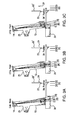
- Figures 3A, 3B, and 3C show the contact carrier having three possible stable Positions: Off (X), Automatic reset (A) and On (O).
- the tripping actuator 12 rotates in an arc from the cold state (C) position in Figure 3A , through the over-center tripping (T) position in Figure 3B , to the Hot state (H) position in Figure 3C , and back. Going from the Cold state (C) to Hot state (H), there are two other positions, the over-center tripping (T) position and the reset (R) position.
- the tripping actuator 12 When pushed during an overload condition, the tripping actuator 12 will rotate until it just passes the over-center tripping (T) position, causing the contact carrier 20 to move to the OFF (X) position.
- Figures 4A and 4B show when the bimetal strip 16A, for example, starts to cool down in the Off (X) position of Figure 4A , and the tripping actuator 12 returns to the reset (R) position.
- a reset button 27' ( Figure 2 ) may be pushed to cause the contact carrier 20 to return to the On (O) Position.
- the reset button 27' may be dimensioned so that it can not push the contact carrier 20 past the over-center tripping (T) position until the bimetal strip 16A, for example, has cooled to a level that would indicate it is safe to start the motor again.
- the moveable contact carrier 20 may further include a second moveable electrical contact (not shown) on or actuated by the moveable contact carrier 20.
- the second moveable electrical contact may be configured to be urged, by the repulsion between the first and second permanent magnets 18 and 28, to remain disconnected in a normally open electrical connection with a second stationary electrical contact (not shown), when the tripping actuator 12 is in the ON position 15 and the moveable contact carrier 20 in the first stable position 26'.
- the second moveable electrical contact may be configured to make a connection with the second stationary electrical contact in the normally open electrical connection, when the first permanent magnet 18 passes the second permanent magnet 28 in the first direction 11 through the over-center tripping (T) position 32.
- the second moveable electrical contact may be configured to break the connection with the second stationary electrical contact in the normally open electrical connection, when the first permanent magnet 18 passes the second permanent magnet 28 in the second direction 13 through the over-center tripping (T) position 32. This occurs when the tripping actuator 12 is moved to the ON position 15 and the moveable contact carrier 20 is in the first stable position 26', in response to the overcurrent condition being sensed to subside, by the overcurrent sensing mechanism 16.
- the overcurrent sensing mechanism of the present invention might use any one of a melting alloy thermal overload sensor, a bimetallic thermal overload sensor, or a solid state overload sensor.
Landscapes
- Physics & Mathematics (AREA)
- Electromagnetism (AREA)
- Thermal Sciences (AREA)
- Breakers (AREA)
Abstract
Description
- The invention disclosed relates to trip mechanism for overload relays.
- Overload relays are intended to protect motors conductors against excessive heating due to prolonged motor overcurrents up to and including locked rotor currents. Overload relays are distinguished from circuit breakers, in that circuit breakers typically protect other types of branch-circuit components from higher currents acting over a shorter interval, due to short circuits or grounds.
- Thermal overload relays sense prolonged motor overcurrent by converting this current to heat in a resistance element. The heat generated is used to open a normally closed contact in series with a starter coil causing the motor to be disconnected from the line.
- Generally, there are three types of overload relays, the melting alloy thermal overload relay, the bimetallic thermal overload relay, and the solid state overload relay.
- In melting alloy thermal overload relays, the motor current passes through a small heater winding. Under overload conditions, the heat causes a special solder to melt, tripping the relay and opening the normally closed contact in series with a starter coil causing the motor to be disconnected from the line.
- Bimetallic thermal overload relays employ a bimetal strip associated with a current carrying heater coil. When an overload occurs, the heat will cause the bi-metal to deflect and trip the relay, opening the normally closed contact in series with a starter coil causing the motor to be disconnected from the line.
- Solid state electronic overload relays do not require thermal units, instead use current transformers that respond directly to the motor current. Once an overload condition is reached, the electronic circuit of the overload relay trips, causing the contacts to open in a manner similar to the bimetallic thermal overload relay, opening the normally closed contact in series with a starter coil causing the motor to be disconnected from the line.
- The normally closed contact in existing overload relays is typically driven by a mechanical bi-stable spring that is tripped by a complex sequence of levers that are difficult to manufacture because of the tolerances they require. Spring actuated bi-stable mechanisms can be difficult to dimension correctly making it difficult to guaranty consistent tripping positions and contact forces. What is needed is a simplified overload tripping mechanism the replaces the mechanical bi-stable spring with a mechanism that does not require difficult manufacturing steps.
- The subject invention provides a simplified overload tripping mechanism for an overload relay, by replacing the mechanical bi-stable spring with two opposing magnets. The magnetically driven trip mechanism is relatively easy to manufacture and provides consistent tripping positions and contact forces in an overload relay. The invention comprises a tripping actuator having a first permanent magnet and a moveable contact carrier having a second permanent magnet mounted in an opposed orientation to the first permanent magnet. A moveable electrical contact on the moveable contact carrier is urged, by repulsion between the magnets, to make electrical connection with a stationary electrical contact, when the tripping actuator is in an ON position and the moveable contact carrier in a first stable position.
- The overload relay may use an overcurrent sensing mechanism, such as a bimetallic thermal overload sensor that employs a bimetal strip associated with a current carrying heater coil. The heater coil may be connected in series with a power source and a motor. The bimetal strip is configured to deflect from heat produced by the heater coil when an overcurrent condition occurs. The bimetal strip is connected to the tripping actuator and when an overcurrent condition is sensed, it moves the tripping actuator.
- When the tripping actuator is moved to an OFF position in response to an overcurrent condition being sensed by the bimetallic thermal overload sensor, the first permanent magnet passes the second permanent magnet in a first direction through an over-center tripping position. The proximity of the first and second permanent magnets causes them to repel each other and urge the moveable contact carrier and its moveable contact toward a second stable position, moving away from the stationary contact in an opposite, second direction, to break the normally closed electrical connection with the stationary electrical contact. The opposing magnets provide the over-center trip function and apply the proper force to open the contacts.
- The invention may include an auto-reset mode to automatically restore the normally closed electrical connection with the stationary electrical contact, after an interval has passed since the overcurrent condition has subsided. When the overcurrent condition subsides and the heater coil cools, the bimetal strip is configured to reverse its deflection, thereby moving the tripping actuator in the second direction, back through the over-center tripping position. The first and second magnets repel each other, to thereby urge the moveable contact carrier and its moveable contact to return toward the first stable position, to make the normally closed electrical connection with the stationary electrical contact. In the auto-reset mode, the contact carrier is blocked in a position so that it cannot move to the full off position, so that when the tripping actuator returns, it can cause the reset automatically. Without the contact carrier blocked, it moves to a position where the tripping actuator cannot move far enough to cause auto reset and a reset button may then be used
- The invention may include an adjustable mount supporting the first magnet, to enable changing the location of the over-center tripping position by adjusting the orientation of the magnet, to thereby change the set point and sensitivity of the mechanism.
- Example embodiments of the invention are depicted in the accompanying drawings that are briefly described as follows:
-
Figure 1 shows a magnetically driven trip mechanism for an overload relay in a normally closed or ON state, wherein a tripping actuator is shown resting in an ON position and a moveable contact carrier is in a first stable position, while there is no overcurrent condition being sensed by a bimetallic thermal overload sensor. -
Figure 2 shows the magnetically driven trip mechanism for the overload relay ofFigure 1 , with the relay in an open or OFF state, wherein the tripping actuator is shown in an OFF position and the moveable contact carrier is in a second stable position, in response to an overcurrent condition being sensed by the bimetallic thermal overload sensor. -
Figures 3A, 3B, and 3C show the contact carrier having three possible stable Positions: Off (X), Automatic reset (A) and On (O). When pushed during an overload condition, the tripping actuator will rotate until it just passes the over-center tripping (T) position, causing the contact carrier to move to the OFF (X) position. -
Figures 4A and 4B show when the bimetal strip starts to cool down in the Off (X) position, the tripping actuator may return to an automatic reset (A) position, in an auto-reset embodiment of the invention. The contact carrier will automatically move to the On (O) position as soon as the bimetal strip cools to the point where it has pulled the tripping actuator back to a Reset (R) position. -
Figure 1 shows a magnetically driven trip mechanism for an overload relay in a normally closed or ON state. In an example embodiment of the invention, the overload relay may be contained in a housing 10'. In an example embodiment of the invention, the overload relay may use an overcurrent sensing mechanism, such as a bimetallicthermal overload sensor 16 that employs abimetal strip 16A associated with a current carryingheater coil 16A'. The heater coil may be connected in series with one phase of a power source and a motor. The bimetallicthermal overload sensor 16 shown in the figure, employs threebimetal strips bimetal strip respective heater 16A', 16B' and 16C'. Each bimetal strip, for example 16A, is configured to deflect from heat produced by itsheater coil 16A' when an overcurrent condition occurs in that phase. When any one of the threebimetal strips displacement bar 16D and lever 17 with it. Thedisplacement bar 16D and lever 17 push on the bimetalcompensation lever assembly pivot 19P. When the bimetalcompensation lever assembly lever 21 pushes on the bimetal compensation subassembly link orinterface 25, referred to herein by the shorter expression "bimetal interface" 25, of thetripping actuator 12. Thus, when an overcurrent condition is sensed,bimetal interface 25 moves thetripping actuator 12. - In the example embodiment, the
tripping actuator 12 is mechanically coupled in this manner to the bimetallicthermal overload sensor 16. The trippingactuator 12 has a pivoted end mounted on apivot 14 on abase 10 in the housing 10'. Thetripping actuator 12 is shown inFigure 1 , resting in anON position 15 while there is no overcurrent condition being sensed by the bimetallicthermal overload sensor 16. In alternate embodiments of the invention, the tripping level may have a linear sliding motion with respect to the contact carrier. - The
tripping actuator 12 has a firstpermanent magnet 18 mounted on an end opposite to the pivoted end, with north-south poles of the firstpermanent magnet 18 oriented in a substantially radial direction with respect to thepivot 14. The firstpermanent magnet 18 moves in thefirst direction 11 when the bimetallicthermal overload sensor 16 causes thetripping actuator 12 to move in thefirst direction 11 in response to an overcurrent condition being sensed by the bimetallicthermal overload sensor 16. When an overload occurs, the heat will cause thebimetal strip 16A to deflect and move thetripping actuator 12 in thefirst direction 11. - A
moveable contact carrier 20 is slideably mounted on thebase 10. Themoveable contact carrier 20 includes a moveableelectrical contact 22 of the overload relay. The moveableelectrical contact 22 may be on or actuated by thecontact carrier 20. The moveableelectrical contact 22 may be located near the end of a flexible conductor wire 22'. The moveableelectrical contact 22 is in a normally closed electrical connection with a stationaryelectrical contact 24 of the overload relay, as shown inFigure 1 , when themoveable contact carrier 20 is in a first stable position 26' on thebase 10. Themoveable contact carrier 20 has a secondpermanent magnet 28 mounted thereon, with north-south poles of the secondpermanent magnet 28 being oriented in a substantially opposite direction with respect to the direction of orientation of the north-south poles of the firstpermanent magnet 18. The firstpermanent magnet 18 and the secondpermanent magnet 28 repel one other to urge the moveableelectrical contact 22 in thefirst direction 11 toward the stationaryelectrical contact 24 in the normally closed electrical connection ofFigure 1 , when themoveable contact carrier 20 is in the first stable position 26' on thebase 10 and the trippingactuator 12 is resting in theON position 15 ofFigure 1 . -
Figure 2 shows the magnetically driven trip mechanism for an overload relay ofFigure 1 , with the relay in an open or OFF state, wherein the trippingactuator 12 is shown in anOFF position 23 in response to an overcurrent condition being sensed by the bimetallicthermal overload sensor 16. The trippingactuator 12 moves in thefirst direction 11 to theOFF position 23 inFigure 2 , in response to an overcurrent condition being sensed by the bimetallicthermal overload sensor 16. The bimetal strip is configured to deflect from heat produced by the heater coil when an overcurrent condition occurs, thereby moving the trippingactuator 12 in thefirst direction 11, through the over-center tripping (T)position 32. - The first
permanent magnet 18 passes through the over-center tripping (T)position 32 when the firstpermanent magnet 18 moves in thefirst direction 11 past the secondpermanent magnet 28. Their proximity causes the firstpermanent magnet 18 and the secondpermanent magnet 28 to repel each other and urge themoveable contact carrier 20 and its moveableelectrical contact 22 to slide in thesecond direction 13 toward a secondstable position 26 away from the stationaryelectrical contact 24, as shown inFigure 2 . This causes the moveableelectrical contact 22 to break the normally closed electrical connection with the stationaryelectrical contact 24 of the overload relay. -
Figures 1 and2 show an auto-reset embodiment of the invention. After the overcurrent condition subsides and the heater coil cools in the bimetallicthermal overload sensor 16, the trippingactuator 12 returns to rest in theON position 15 inFigure 1 . In this mode, the cooling of thebimetal strip 16A causes it to reverse its deflection and go to the left in the figure. Thedisplacement bar 16D andlever 17 pull on the bimetalcompensation lever assembly pivot 19P. When the bimetalcompensation lever assembly lever 21 pulls on thebimetal interface 25 of the trippingactuator 12, in thesecond direction 13 back through the over-center tripping (T)position 32. - As the tripping
actuator 12 returns to rest in theON position 15 inFigure 1 , the firstpermanent magnet 18 and the secondpermanent magnet 28 pass through the over-center tripping (T)position 32 as the firstpermanent magnet 18 moves in thesecond direction 13 past the secondpermanent magnet 28. This causes the firstpermanent magnet 18 and the secondpermanent magnet 28 to repel each other and urge themoveable contact carrier 20 toward the first stable position 26' inFigure 1 , with its moveableelectrical contact 22 moving in thefirst direction 11 toward the stationaryelectrical contact 24. In this manner, themoveable contact carrier 20 automatically makes the normally closed electrical connection with the stationaryelectrical contact 24 of the overload relay. - An adjustable mounting 30 on the tripping
actuator 12 supports thefirst magnet 18. The degree of repulsion between the firstpermanent magnet 18 and the secondpermanent magnet 28 may be adjusted by rotating the adjustable mounting 30 to change the orientation of thefirst magnet 18 in the adjustable mounting 30, thereby changing a location of the over-center tripping (T)position 32, and the set point and sensitivity of the mechanism. - A manual reset button 27' (
Figures 1 and2 ) may be juxtaposed with a wedge-shaped projection 27 (Figures 1 and2 ) on themoveable contact carrier 20. The manual reset button 27' may be configured to move themoveable contact carrier 20 and the moveableelectrical contact 22 toward the stationaryelectrical contact 24, to restore the normally closed electrical connection with the stationaryelectrical contact 24 of the overload relay. -
Figures 3A, 3B, and 3C show the contact carrier having three possible stable Positions: Off (X), Automatic reset (A) and On (O). When pushed (or pulled) by the bimetalcompensation lever assembly 19 and 21 (Figure 2 ), the trippingactuator 12 rotates in an arc from the cold state (C) position inFigure 3A , through the over-center tripping (T) position inFigure 3B , to the Hot state (H) position inFigure 3C , and back. Going from the Cold state (C) to Hot state (H), there are two other positions, the over-center tripping (T) position and the reset (R) position. When pushed during an overload condition, the trippingactuator 12 will rotate until it just passes the over-center tripping (T) position, causing thecontact carrier 20 to move to the OFF (X) position. -
Figures 4A and 4B show when thebimetal strip 16A, for example, starts to cool down in the Off (X) position ofFigure 4A , and the trippingactuator 12 returns to the reset (R) position. A reset button 27' (Figure 2 ) may be pushed to cause thecontact carrier 20 to return to the On (O) Position. The reset button 27' may be dimensioned so that it can not push thecontact carrier 20 past the over-center tripping (T) position until thebimetal strip 16A, for example, has cooled to a level that would indicate it is safe to start the motor again. - In the auto-reset embodiment shown in the figures, there is also an automatic reset (A) position of
Figure 4B , where thecontact carrier 20 is blocked in a position so that it cannot move to the full Off (X) position. In this mode, thecontact carrier 20 will move to the On (O) position as soon as thebimetal strip 16A, for example, cools to the point where it has pulled the trippingactuator 12 back to the Reset (R) position. This blocked position is basically the same point to which the reset button 27' would move thecontact carrier 20. - In an alternate example embodiment of the invention, the
moveable contact carrier 20 may further include a second moveable electrical contact (not shown) on or actuated by themoveable contact carrier 20. The second moveable electrical contact may be configured to be urged, by the repulsion between the first and secondpermanent magnets actuator 12 is in theON position 15 and themoveable contact carrier 20 in the first stable position 26'. The second moveable electrical contact may be configured to make a connection with the second stationary electrical contact in the normally open electrical connection, when the firstpermanent magnet 18 passes the secondpermanent magnet 28 in thefirst direction 11 through the over-center tripping (T)position 32. This occurs when the trippingactuator 12 is moved to theOFF position 23 and themoveable contact carrier 20 is in the secondstable position 26 in response to the overcurrent condition being sensed by theovercurrent sensing mechanism 16. The second moveable electrical contact may be configured to break the connection with the second stationary electrical contact in the normally open electrical connection, when the firstpermanent magnet 18 passes the secondpermanent magnet 28 in thesecond direction 13 through the over-center tripping (T)position 32. This occurs when the trippingactuator 12 is moved to theON position 15 and themoveable contact carrier 20 is in the first stable position 26', in response to the overcurrent condition being sensed to subside, by theovercurrent sensing mechanism 16. - The overcurrent sensing mechanism of the present invention might use any one of a melting alloy thermal overload sensor, a bimetallic thermal overload sensor, or a solid state overload sensor.
- Although specific example embodiments of the invention have been disclosed, persons of skill in the art will appreciate that changes may be made to the details described for the specific example embodiments, without departing from the spirit and the scope of the invention.
Claims (11)
- A magnetically driven trip mechanism for an overload relay, comprising:a tripping actuator having a first permanent magnet;a moveable contact carrier having a second permanent magnet mounted in an opposed orientation to the first permanent magnet;a moveable electrical contact on or actuated by the moveable contact carrier, the moveable electrical contact configured to be urged, by repulsion between the first and second permanent magnets, to make a normally closed electrical connection with a stationary electrical contact, when the tripping actuator is in an ON position and the moveable contact carrier in a first stable position;the first permanent magnet passing the second permanent magnet in a first direction through an over-center tripping position when the tripping actuator is moved to an OFF position in response to an overcurrent condition being sensed by an overcurrent sensing mechanism; andthe first and second permanent magnets being configured to repel each other after the first permanent magnet passes through the over-center tripping position, to thereby urge the moveable contact carrier and its moveable contact toward a second stable position, the moveable contact thereby moving in a second direction opposite to the first direction, to break the normally closed electrical connection with the stationary electrical contact.
- The magnetically driven trip mechanism for an overload relay of claim 1, further comprising:the first permanent magnet passing the second permanent magnet in the second direction opposite to the first direction, through the over-center tripping position, when the tripping actuator is moved to an ON position after the overcurrent condition subsides; andthe first and second permanent magnets being configured to repel each other after the first permanent magnet passes through the over-center tripping position in the second direction, to thereby urge the moveable contact carrier and its moveable contact toward the first stable position, the moveable contact thereby moving toward the stationary contact, to make the normally closed electrical connections with the stationary electrical contact.
- The magnetically driven trip mechanism for an overload relay of claim 1, further comprising:an adjustable mounting on the tripping actuator, the adjustable mounting supporting the first magnet, the repulsion between the first and second magnets being adjustable by changing the orientation of the first magnet in the adjustable mounting, thereby changing a location of the tripping position.
- The magnetically driven trip mechanism for an overload relay of claim 1, wherein the overcurrent sensing mechanism is a bimetallic thermal overload sensor.
- The magnetically driven trip mechanism for an overload relay of claim 1, wherein the overcurrent sensing mechanism is a bimetallic thermal overload sensor that employs a bimetal strip associated with a current carrying heater coil connected in series with a power source and a motor, the bimetal strip being configured to deflect from heat produced by the heater coil when an overcurrent condition occurs, thereby moving the tripping actuator in the first direction, through the over-center tripping position.
- The magnetically driven trip mechanism for an overload relay of claim 5, wherein when the overcurrent condition subsides and the heater coil cools, the bimetal strip is configured to reverse its deflection, thereby moving the tripping actuator in the second direction, back through the over-center tripping position.
- The magnetically driven trip mechanism for an overload relay of claim 1, wherein the tripping actuator has a pivoted end mounted on a pivot on a base, the tripping actuator having the first permanent magnet mounted on an end opposite to the pivoted end, with north-south poles of the first permanent magnet oriented in a substantially radial direction with respect to the pivot, the first permanent magnet moving in the first direction when the overcurrent sensing mechanism causes the tripping actuator to move in the first direction in response to the overcurrent condition being sensed by the overcurrent sensing mechanism; and
wherein the moveable contact carrier is slideably mounted on the base, the moveable contact carrier having the second permanent magnet mounted thereon with north-south poles of the second permanent magnet being oriented in a substantially opposite direction with respect to the direction of orientation of the north-south poles of the first permanent magnet, the moveable contact carrier and its moveable electrical contact sliding in the second direction away from the stationary electrical contact, when the tripping actuator is moved to the OFF position in response to the overcurrent condition being sensed by an overcurrent sensing mechanism - The magnetically driven trip mechanism for an overload relay of claim 1, wherein the overcurrent sensing mechanism is connected in series with a power source and a motor, the overcurrent sensing mechanism being configured to sense a prolonged motor overcurrent.
- The magnetically driven trip mechanism for an overload relay of claim 1, wherein, in response to the overcurrent condition being sensed to subside by the overcurrent sensing mechanism, the tripping actuator moves in the second direction back through the over-center tripping position, thereby urging the contact carrier toward the first stable position and moving the moveable electrical contact in the first direction toward the stationary electrical contact, to thereby automatically reset the normally closed electrical connection with the stationary electrical contact.
- The magnetically driven trip mechanism for an overload relay of claim 1, further comprising:the moveable contact carrier further including a second moveable electrical contact on or actuated by the moveable contact carrier, the second moveable electrical contact configured to be urged, by the repulsion between the first and second permanent magnets, to remain disconnected in a normally open electrical connection with a second stationary electrical contact, when the tripping actuator is in the ON position and the moveable contact carrier in the first stable position;the second moveable electrical contact configured to make a connection with the second stationary electrical contact in the normally open electrical connection, when the first permanent magnet passes the second permanent magnet in the first direction through the over-center tripping position, when the tripping actuator is moved to the OFF position and the moveable contact carrier is in the second stable position in response to the overcurrent condition being sensed by the overcurrent sensing mechanism.
- The magnetically driven trip mechanism for an overload relay of claim 11, further comprising:the second moveable electrical contact configured to break the connection with the second stationary electrical contact in the normally open electrical connection, when the first permanent magnet passes the second permanent magnet in the second direction through the over-center tripping position, when the tripping actuator is moved to the ON position and the moveable contact carrier is in the first stable position in response to the overcurrent condition being sensed to subside, by the overcurrent sensing mechanism.
Applications Claiming Priority (1)
| Application Number | Priority Date | Filing Date | Title |
|---|---|---|---|
| US14/526,863 US9711307B2 (en) | 2014-10-29 | 2014-10-29 | Magnetically driven trip mechanism for an overload relay |
Publications (2)
| Publication Number | Publication Date |
|---|---|
| EP3016126A1 true EP3016126A1 (en) | 2016-05-04 |
| EP3016126B1 EP3016126B1 (en) | 2017-05-17 |
Family
ID=54196905
Family Applications (1)
| Application Number | Title | Priority Date | Filing Date |
|---|---|---|---|
| EP15186544.1A Active EP3016126B1 (en) | 2014-10-29 | 2015-09-23 | Magnetically driven trip mechanism for an overload relay |
Country Status (2)
| Country | Link |
|---|---|
| US (1) | US9711307B2 (en) |
| EP (1) | EP3016126B1 (en) |
Cited By (1)
| Publication number | Priority date | Publication date | Assignee | Title |
|---|---|---|---|---|
| WO2021156454A1 (en) * | 2020-02-07 | 2021-08-12 | Eaton Intelligent Power Ltd. | Circuit breaker and method for operating a circuit breaker |
Families Citing this family (3)
| Publication number | Priority date | Publication date | Assignee | Title |
|---|---|---|---|---|
| US20250157763A1 (en) * | 2023-11-09 | 2025-05-15 | Rockwell Automation Switzerland Gmbh | Circuit breaker compensation bimetal of a thermal tripping mechanism |
| US12626872B2 (en) | 2023-11-09 | 2026-05-12 | Rockwell Automation Switzerland Gmbh | Circuit breaker linear lever and tripping fork mechanism |
| US12626879B2 (en) | 2023-11-09 | 2026-05-12 | Rockwell Automation Technologies, Inc. | Circuit breaker tripping mechanism |
Citations (2)
| Publication number | Priority date | Publication date | Assignee | Title |
|---|---|---|---|---|
| US4739291A (en) * | 1986-12-08 | 1988-04-19 | Lee Wen Fong | Magnetic vacuum circuit breaker |
| US5777536A (en) * | 1996-06-05 | 1998-07-07 | Lee; Wen-Fong | Sealed electric switch assembly |
Family Cites Families (21)
| Publication number | Priority date | Publication date | Assignee | Title |
|---|---|---|---|---|
| US2951129A (en) | 1958-02-25 | 1960-08-30 | Donald H Mink | Snap switch |
| US3194912A (en) | 1963-10-22 | 1965-07-13 | Molex Products Co | Double snap-action magnetically actuated toggle switch |
| US4296394A (en) | 1978-02-13 | 1981-10-20 | Ragheb A Kadry | Magnetic switching device for contact-dependent and contactless switching |
| US4888531A (en) * | 1987-02-12 | 1989-12-19 | Hormann Kg Antriebs- Und Steuerungstechnik | Variable drive mechanism for the panel of a gate or similar structure |
| US5332986A (en) | 1993-04-13 | 1994-07-26 | Allen-Bradley Company, Inc. | Overload relay mechanism |
| FR2706220B1 (en) | 1993-06-07 | 1995-07-21 | Telemecanique | Protection switch device with control mechanism. |
| US6720852B2 (en) * | 2002-08-26 | 2004-04-13 | Honeywell International Inc. | Methods and apparatus for actuating and deactuating a switching device using magnets |
| GB0301167D0 (en) * | 2003-01-18 | 2003-02-19 | Ceramaspeed Ltd | Temperature-limiting device |
| JP4479768B2 (en) | 2007-09-10 | 2010-06-09 | トヨタ自動車株式会社 | Automobile and auto charging method |
| TWM358914U (en) * | 2008-05-09 | 2009-06-11 | li-min Zhao | Magnetic wire-controlled switch |
| JP4906881B2 (en) * | 2009-03-27 | 2012-03-28 | 富士電機機器制御株式会社 | Thermal overload relay |
| US8222982B2 (en) | 2009-12-28 | 2012-07-17 | Schneider Electric USA, Inc. | Overload relay trip mechanism |
| US8558504B2 (en) | 2010-01-11 | 2013-10-15 | Leviton Manufacturing Co., Inc. | Electric vehicle supply equipment with timer |
| WO2011127446A2 (en) | 2010-04-09 | 2011-10-13 | Aerovironment, Inc. | Portable charging cable with in-line controller |
| EP2395535B1 (en) * | 2010-06-08 | 2013-10-30 | Eaton Electrical IP GmbH & Co. KG | Tripping unit for a circuit breaker |
| US8410875B2 (en) | 2010-06-30 | 2013-04-02 | Eaton Corporation | Overload relay switch without springs |
| JP2012023792A (en) * | 2010-07-12 | 2012-02-02 | Sinfonia Technology Co Ltd | Movable iron core type linear actuator |
| WO2012099978A2 (en) | 2011-01-19 | 2012-07-26 | Aerovironment, Inc. | Electric vehicle docking connector with embedded evse controller |
| US8587911B2 (en) | 2011-05-12 | 2013-11-19 | Control Module, Inc. | Service line safety monitor |
| DE102011084527A1 (en) | 2011-10-14 | 2013-04-18 | Siemens Aktiengesellschaft | Charging infrastructure for electric vehicles |
| US9324529B2 (en) * | 2014-04-14 | 2016-04-26 | Eaton Corporation | Current direction sensitive circuit interrupter |
-
2014
- 2014-10-29 US US14/526,863 patent/US9711307B2/en active Active
-
2015
- 2015-09-23 EP EP15186544.1A patent/EP3016126B1/en active Active
Patent Citations (2)
| Publication number | Priority date | Publication date | Assignee | Title |
|---|---|---|---|---|
| US4739291A (en) * | 1986-12-08 | 1988-04-19 | Lee Wen Fong | Magnetic vacuum circuit breaker |
| US5777536A (en) * | 1996-06-05 | 1998-07-07 | Lee; Wen-Fong | Sealed electric switch assembly |
Cited By (2)
| Publication number | Priority date | Publication date | Assignee | Title |
|---|---|---|---|---|
| WO2021156454A1 (en) * | 2020-02-07 | 2021-08-12 | Eaton Intelligent Power Ltd. | Circuit breaker and method for operating a circuit breaker |
| US12062514B2 (en) | 2020-02-07 | 2024-08-13 | Eaton Intelligent Power Limited | Circuit breaker and method for operating a circuit breaker |
Also Published As
| Publication number | Publication date |
|---|---|
| US20160126039A1 (en) | 2016-05-05 |
| US9711307B2 (en) | 2017-07-18 |
| EP3016126B1 (en) | 2017-05-17 |
Similar Documents
| Publication | Publication Date | Title |
|---|---|---|
| CN102568955B (en) | The circuit breaker of shape memory alloy actuated | |
| EP3016126B1 (en) | Magnetically driven trip mechanism for an overload relay | |
| EP1939912A1 (en) | Activation for switching apparatus | |
| EP1213738A2 (en) | Arc responsive thermal circuit breaker | |
| US6724591B2 (en) | Circuit interrupter employing a mechanism to open a power circuit in response to a resistor body burning open | |
| US8461947B2 (en) | Installation switching device | |
| CA2899773C (en) | Bimetal and magnetic armature providing an arc splatter resistant offset therebetween, and circuit breaker including the same | |
| AU777311B2 (en) | Circuit breaker with bypass conductor commutating current out of the bimetal during short circuit interruption and method of commutating current out of bimetal | |
| US4090156A (en) | Circuit breaker having solid state and thermal-magnetic trip means | |
| US3950715A (en) | Circuit breaker with improved trip means | |
| US3421123A (en) | Electric circuit breaker with magnetic tripping means | |
| JP6218675B2 (en) | Circuit breaker | |
| EP0150156A2 (en) | Trip assembly for a circuit breaker | |
| US7859369B2 (en) | Method of bi-directional thermal calibration of a circuit interrupter frame and circuit interrupter test system including the same | |
| US20150294825A1 (en) | Current direction sensitive circuit interrupter | |
| CN104040674A (en) | Circuit breaker for wiring | |
| KR20140145191A (en) | Circuit breaker | |
| US2813167A (en) | Circuit breaker | |
| MXPA02011861A (en) | Circuit breaker thermal magnetic trip unit. | |
| CN107210170B (en) | Circuit breakers comprising a passively heated bimetallic element acting on the yoke of an electromagnetic trip unit | |
| US6822543B1 (en) | System and method for controlling trip unit mechanical stress | |
| US3555468A (en) | Combined thermal-magnetic trip means for circuit breakers | |
| KR101759597B1 (en) | Thermal overload relay | |
| US2689285A (en) | Circuit breaker | |
| US3061697A (en) | Thermal and magnetic trip device |
Legal Events
| Date | Code | Title | Description |
|---|---|---|---|
| PUAI | Public reference made under article 153(3) epc to a published international application that has entered the european phase |
Free format text: ORIGINAL CODE: 0009012 |
|
| AK | Designated contracting states |
Kind code of ref document: A1 Designated state(s): AL AT BE BG CH CY CZ DE DK EE ES FI FR GB GR HR HU IE IS IT LI LT LU LV MC MK MT NL NO PL PT RO RS SE SI SK SM TR |
|
| AX | Request for extension of the european patent |
Extension state: BA ME |
|
| 17P | Request for examination filed |
Effective date: 20161011 |
|
| RBV | Designated contracting states (corrected) |
Designated state(s): AL AT BE BG CH CY CZ DE DK EE ES FI FR GB GR HR HU IE IS IT LI LT LU LV MC MK MT NL NO PL PT RO RS SE SI SK SM TR |
|
| RIC1 | Information provided on ipc code assigned before grant |
Ipc: H01H 71/32 20060101AFI20161028BHEP |
|
| GRAP | Despatch of communication of intention to grant a patent |
Free format text: ORIGINAL CODE: EPIDOSNIGR1 |
|
| STAA | Information on the status of an ep patent application or granted ep patent |
Free format text: STATUS: GRANT OF PATENT IS INTENDED |
|
| INTG | Intention to grant announced |
Effective date: 20161213 |
|
| GRAS | Grant fee paid |
Free format text: ORIGINAL CODE: EPIDOSNIGR3 |
|
| GRAA | (expected) grant |
Free format text: ORIGINAL CODE: 0009210 |
|
| STAA | Information on the status of an ep patent application or granted ep patent |
Free format text: STATUS: THE PATENT HAS BEEN GRANTED |
|
| AK | Designated contracting states |
Kind code of ref document: B1 Designated state(s): AL AT BE BG CH CY CZ DE DK EE ES FI FR GB GR HR HU IE IS IT LI LT LU LV MC MK MT NL NO PL PT RO RS SE SI SK SM TR |
|
| RAP1 | Party data changed (applicant data changed or rights of an application transferred) |
Owner name: SCHNEIDER ELECTRIC USA, INC. |
|
| REG | Reference to a national code |
Ref country code: GB Ref legal event code: FG4D |
|
| REG | Reference to a national code |
Ref country code: CH Ref legal event code: EP |
|
| REG | Reference to a national code |
Ref country code: IE Ref legal event code: FG4D |
|
| REG | Reference to a national code |
Ref country code: AT Ref legal event code: REF Ref document number: 895156 Country of ref document: AT Kind code of ref document: T Effective date: 20170615 |
|
| REG | Reference to a national code |
Ref country code: DE Ref legal event code: R096 Ref document number: 602015002751 Country of ref document: DE |
|
| REG | Reference to a national code |
Ref country code: NL Ref legal event code: MP Effective date: 20170517 |
|
| REG | Reference to a national code |
Ref country code: LT Ref legal event code: MG4D |
|
| REG | Reference to a national code |
Ref country code: AT Ref legal event code: MK05 Ref document number: 895156 Country of ref document: AT Kind code of ref document: T Effective date: 20170517 |
|
| PG25 | Lapsed in a contracting state [announced via postgrant information from national office to epo] |
Ref country code: LT Free format text: LAPSE BECAUSE OF FAILURE TO SUBMIT A TRANSLATION OF THE DESCRIPTION OR TO PAY THE FEE WITHIN THE PRESCRIBED TIME-LIMIT Effective date: 20170517 Ref country code: AT Free format text: LAPSE BECAUSE OF FAILURE TO SUBMIT A TRANSLATION OF THE DESCRIPTION OR TO PAY THE FEE WITHIN THE PRESCRIBED TIME-LIMIT Effective date: 20170517 Ref country code: NO Free format text: LAPSE BECAUSE OF FAILURE TO SUBMIT A TRANSLATION OF THE DESCRIPTION OR TO PAY THE FEE WITHIN THE PRESCRIBED TIME-LIMIT Effective date: 20170817 Ref country code: GR Free format text: LAPSE BECAUSE OF FAILURE TO SUBMIT A TRANSLATION OF THE DESCRIPTION OR TO PAY THE FEE WITHIN THE PRESCRIBED TIME-LIMIT Effective date: 20170818 Ref country code: ES Free format text: LAPSE BECAUSE OF FAILURE TO SUBMIT A TRANSLATION OF THE DESCRIPTION OR TO PAY THE FEE WITHIN THE PRESCRIBED TIME-LIMIT Effective date: 20170517 Ref country code: HR Free format text: LAPSE BECAUSE OF FAILURE TO SUBMIT A TRANSLATION OF THE DESCRIPTION OR TO PAY THE FEE WITHIN THE PRESCRIBED TIME-LIMIT Effective date: 20170517 Ref country code: FI Free format text: LAPSE BECAUSE OF FAILURE TO SUBMIT A TRANSLATION OF THE DESCRIPTION OR TO PAY THE FEE WITHIN THE PRESCRIBED TIME-LIMIT Effective date: 20170517 |
|
| PG25 | Lapsed in a contracting state [announced via postgrant information from national office to epo] |
Ref country code: IS Free format text: LAPSE BECAUSE OF FAILURE TO SUBMIT A TRANSLATION OF THE DESCRIPTION OR TO PAY THE FEE WITHIN THE PRESCRIBED TIME-LIMIT Effective date: 20170917 Ref country code: NL Free format text: LAPSE BECAUSE OF FAILURE TO SUBMIT A TRANSLATION OF THE DESCRIPTION OR TO PAY THE FEE WITHIN THE PRESCRIBED TIME-LIMIT Effective date: 20170517 Ref country code: LV Free format text: LAPSE BECAUSE OF FAILURE TO SUBMIT A TRANSLATION OF THE DESCRIPTION OR TO PAY THE FEE WITHIN THE PRESCRIBED TIME-LIMIT Effective date: 20170517 Ref country code: SE Free format text: LAPSE BECAUSE OF FAILURE TO SUBMIT A TRANSLATION OF THE DESCRIPTION OR TO PAY THE FEE WITHIN THE PRESCRIBED TIME-LIMIT Effective date: 20170517 Ref country code: BG Free format text: LAPSE BECAUSE OF FAILURE TO SUBMIT A TRANSLATION OF THE DESCRIPTION OR TO PAY THE FEE WITHIN THE PRESCRIBED TIME-LIMIT Effective date: 20170817 Ref country code: PL Free format text: LAPSE BECAUSE OF FAILURE TO SUBMIT A TRANSLATION OF THE DESCRIPTION OR TO PAY THE FEE WITHIN THE PRESCRIBED TIME-LIMIT Effective date: 20170517 Ref country code: RS Free format text: LAPSE BECAUSE OF FAILURE TO SUBMIT A TRANSLATION OF THE DESCRIPTION OR TO PAY THE FEE WITHIN THE PRESCRIBED TIME-LIMIT Effective date: 20170517 |
|
| PG25 | Lapsed in a contracting state [announced via postgrant information from national office to epo] |
Ref country code: DK Free format text: LAPSE BECAUSE OF FAILURE TO SUBMIT A TRANSLATION OF THE DESCRIPTION OR TO PAY THE FEE WITHIN THE PRESCRIBED TIME-LIMIT Effective date: 20170517 Ref country code: RO Free format text: LAPSE BECAUSE OF FAILURE TO SUBMIT A TRANSLATION OF THE DESCRIPTION OR TO PAY THE FEE WITHIN THE PRESCRIBED TIME-LIMIT Effective date: 20170517 Ref country code: CZ Free format text: LAPSE BECAUSE OF FAILURE TO SUBMIT A TRANSLATION OF THE DESCRIPTION OR TO PAY THE FEE WITHIN THE PRESCRIBED TIME-LIMIT Effective date: 20170517 Ref country code: SK Free format text: LAPSE BECAUSE OF FAILURE TO SUBMIT A TRANSLATION OF THE DESCRIPTION OR TO PAY THE FEE WITHIN THE PRESCRIBED TIME-LIMIT Effective date: 20170517 Ref country code: EE Free format text: LAPSE BECAUSE OF FAILURE TO SUBMIT A TRANSLATION OF THE DESCRIPTION OR TO PAY THE FEE WITHIN THE PRESCRIBED TIME-LIMIT Effective date: 20170517 |
|
| REG | Reference to a national code |
Ref country code: DE Ref legal event code: R097 Ref document number: 602015002751 Country of ref document: DE |
|
| PG25 | Lapsed in a contracting state [announced via postgrant information from national office to epo] |
Ref country code: IT Free format text: LAPSE BECAUSE OF FAILURE TO SUBMIT A TRANSLATION OF THE DESCRIPTION OR TO PAY THE FEE WITHIN THE PRESCRIBED TIME-LIMIT Effective date: 20170517 Ref country code: SM Free format text: LAPSE BECAUSE OF FAILURE TO SUBMIT A TRANSLATION OF THE DESCRIPTION OR TO PAY THE FEE WITHIN THE PRESCRIBED TIME-LIMIT Effective date: 20170517 |
|
| REG | Reference to a national code |
Ref country code: FR Ref legal event code: PLFP Year of fee payment: 3 |
|
| PLBE | No opposition filed within time limit |
Free format text: ORIGINAL CODE: 0009261 |
|
| STAA | Information on the status of an ep patent application or granted ep patent |
Free format text: STATUS: NO OPPOSITION FILED WITHIN TIME LIMIT |
|
| 26N | No opposition filed |
Effective date: 20180220 |
|
| PG25 | Lapsed in a contracting state [announced via postgrant information from national office to epo] |
Ref country code: SI Free format text: LAPSE BECAUSE OF FAILURE TO SUBMIT A TRANSLATION OF THE DESCRIPTION OR TO PAY THE FEE WITHIN THE PRESCRIBED TIME-LIMIT Effective date: 20170517 Ref country code: MC Free format text: LAPSE BECAUSE OF FAILURE TO SUBMIT A TRANSLATION OF THE DESCRIPTION OR TO PAY THE FEE WITHIN THE PRESCRIBED TIME-LIMIT Effective date: 20170517 |
|
| REG | Reference to a national code |
Ref country code: IE Ref legal event code: MM4A |
|
| REG | Reference to a national code |
Ref country code: BE Ref legal event code: MM Effective date: 20170930 |
|
| PG25 | Lapsed in a contracting state [announced via postgrant information from national office to epo] |
Ref country code: LU Free format text: LAPSE BECAUSE OF NON-PAYMENT OF DUE FEES Effective date: 20170923 |
|
| PG25 | Lapsed in a contracting state [announced via postgrant information from national office to epo] |
Ref country code: IE Free format text: LAPSE BECAUSE OF NON-PAYMENT OF DUE FEES Effective date: 20170923 |
|
| PG25 | Lapsed in a contracting state [announced via postgrant information from national office to epo] |
Ref country code: BE Free format text: LAPSE BECAUSE OF NON-PAYMENT OF DUE FEES Effective date: 20170930 |
|
| REG | Reference to a national code |
Ref country code: FR Ref legal event code: PLFP Year of fee payment: 4 |
|
| PG25 | Lapsed in a contracting state [announced via postgrant information from national office to epo] |
Ref country code: MT Free format text: LAPSE BECAUSE OF NON-PAYMENT OF DUE FEES Effective date: 20170923 |
|
| REG | Reference to a national code |
Ref country code: CH Ref legal event code: PL |
|
| PG25 | Lapsed in a contracting state [announced via postgrant information from national office to epo] |
Ref country code: HU Free format text: LAPSE BECAUSE OF FAILURE TO SUBMIT A TRANSLATION OF THE DESCRIPTION OR TO PAY THE FEE WITHIN THE PRESCRIBED TIME-LIMIT; INVALID AB INITIO Effective date: 20150923 |
|
| PG25 | Lapsed in a contracting state [announced via postgrant information from national office to epo] |
Ref country code: CH Free format text: LAPSE BECAUSE OF NON-PAYMENT OF DUE FEES Effective date: 20180930 Ref country code: LI Free format text: LAPSE BECAUSE OF NON-PAYMENT OF DUE FEES Effective date: 20180930 |
|
| PG25 | Lapsed in a contracting state [announced via postgrant information from national office to epo] |
Ref country code: CY Free format text: LAPSE BECAUSE OF FAILURE TO SUBMIT A TRANSLATION OF THE DESCRIPTION OR TO PAY THE FEE WITHIN THE PRESCRIBED TIME-LIMIT Effective date: 20170517 |
|
| PG25 | Lapsed in a contracting state [announced via postgrant information from national office to epo] |
Ref country code: MK Free format text: LAPSE BECAUSE OF FAILURE TO SUBMIT A TRANSLATION OF THE DESCRIPTION OR TO PAY THE FEE WITHIN THE PRESCRIBED TIME-LIMIT Effective date: 20170517 |
|
| PG25 | Lapsed in a contracting state [announced via postgrant information from national office to epo] |
Ref country code: TR Free format text: LAPSE BECAUSE OF FAILURE TO SUBMIT A TRANSLATION OF THE DESCRIPTION OR TO PAY THE FEE WITHIN THE PRESCRIBED TIME-LIMIT Effective date: 20170517 |
|
| PG25 | Lapsed in a contracting state [announced via postgrant information from national office to epo] |
Ref country code: PT Free format text: LAPSE BECAUSE OF FAILURE TO SUBMIT A TRANSLATION OF THE DESCRIPTION OR TO PAY THE FEE WITHIN THE PRESCRIBED TIME-LIMIT Effective date: 20170517 |
|
| PG25 | Lapsed in a contracting state [announced via postgrant information from national office to epo] |
Ref country code: AL Free format text: LAPSE BECAUSE OF FAILURE TO SUBMIT A TRANSLATION OF THE DESCRIPTION OR TO PAY THE FEE WITHIN THE PRESCRIBED TIME-LIMIT Effective date: 20170517 |
|
| PGFP | Annual fee paid to national office [announced via postgrant information from national office to epo] |
Ref country code: DE Payment date: 20250926 Year of fee payment: 11 |
|
| PGFP | Annual fee paid to national office [announced via postgrant information from national office to epo] |
Ref country code: GB Payment date: 20250923 Year of fee payment: 11 |
|
| PGFP | Annual fee paid to national office [announced via postgrant information from national office to epo] |
Ref country code: FR Payment date: 20250925 Year of fee payment: 11 |