EP3015813A1 - Dispositif de camouflage thermique et vehicule comportant un tel dispositif - Google Patents
Dispositif de camouflage thermique et vehicule comportant un tel dispositif Download PDFInfo
- Publication number
- EP3015813A1 EP3015813A1 EP15191991.7A EP15191991A EP3015813A1 EP 3015813 A1 EP3015813 A1 EP 3015813A1 EP 15191991 A EP15191991 A EP 15191991A EP 3015813 A1 EP3015813 A1 EP 3015813A1
- Authority
- EP
- European Patent Office
- Prior art keywords
- pipes
- thermal
- vehicle
- manifold
- pipe
- Prior art date
- Legal status (The legal status is an assumption and is not a legal conclusion. Google has not performed a legal analysis and makes no representation as to the accuracy of the status listed.)
- Granted
Links
Images




Classifications
-
- F—MECHANICAL ENGINEERING; LIGHTING; HEATING; WEAPONS; BLASTING
- F41—WEAPONS
- F41H—ARMOUR; ARMOURED TURRETS; ARMOURED OR ARMED VEHICLES; MEANS OF ATTACK OR DEFENCE, e.g. CAMOUFLAGE, IN GENERAL
- F41H3/00—Camouflage, i.e. means or methods for concealment or disguise
-
- F—MECHANICAL ENGINEERING; LIGHTING; HEATING; WEAPONS; BLASTING
- F28—HEAT EXCHANGE IN GENERAL
- F28D—HEAT-EXCHANGE APPARATUS, NOT PROVIDED FOR IN ANOTHER SUBCLASS, IN WHICH THE HEAT-EXCHANGE MEDIA DO NOT COME INTO DIRECT CONTACT
- F28D1/00—Heat-exchange apparatus having stationary conduit assemblies for one heat-exchange medium only, the media being in contact with different sides of the conduit wall, in which the other heat-exchange medium is a large body of fluid, e.g. domestic or motor car radiators
- F28D1/02—Heat-exchange apparatus having stationary conduit assemblies for one heat-exchange medium only, the media being in contact with different sides of the conduit wall, in which the other heat-exchange medium is a large body of fluid, e.g. domestic or motor car radiators with heat-exchange conduits immersed in the body of fluid
- F28D1/04—Heat-exchange apparatus having stationary conduit assemblies for one heat-exchange medium only, the media being in contact with different sides of the conduit wall, in which the other heat-exchange medium is a large body of fluid, e.g. domestic or motor car radiators with heat-exchange conduits immersed in the body of fluid with tubular conduits
- F28D1/053—Heat-exchange apparatus having stationary conduit assemblies for one heat-exchange medium only, the media being in contact with different sides of the conduit wall, in which the other heat-exchange medium is a large body of fluid, e.g. domestic or motor car radiators with heat-exchange conduits immersed in the body of fluid with tubular conduits the conduits being straight
- F28D1/05316—Assemblies of conduits connected to common headers, e.g. core type radiators
- F28D1/05325—Assemblies of conduits connected to common headers, e.g. core type radiators with particular pattern of flow, e.g. change of flow direction
-
- F—MECHANICAL ENGINEERING; LIGHTING; HEATING; WEAPONS; BLASTING
- F28—HEAT EXCHANGE IN GENERAL
- F28F—DETAILS OF HEAT-EXCHANGE AND HEAT-TRANSFER APPARATUS, OF GENERAL APPLICATION
- F28F11/00—Arrangements for sealing leaky tubes and conduits
- F28F11/06—Arrangements for sealing leaky tubes and conduits using automatic tube obturating appliances
-
- F—MECHANICAL ENGINEERING; LIGHTING; HEATING; WEAPONS; BLASTING
- F28—HEAT EXCHANGE IN GENERAL
- F28F—DETAILS OF HEAT-EXCHANGE AND HEAT-TRANSFER APPARATUS, OF GENERAL APPLICATION
- F28F13/00—Arrangements for modifying heat-transfer, e.g. increasing, decreasing
-
- F—MECHANICAL ENGINEERING; LIGHTING; HEATING; WEAPONS; BLASTING
- F28—HEAT EXCHANGE IN GENERAL
- F28F—DETAILS OF HEAT-EXCHANGE AND HEAT-TRANSFER APPARATUS, OF GENERAL APPLICATION
- F28F13/00—Arrangements for modifying heat-transfer, e.g. increasing, decreasing
- F28F13/18—Arrangements for modifying heat-transfer, e.g. increasing, decreasing by applying coatings, e.g. radiation-absorbing, radiation-reflecting; by surface treatment, e.g. polishing
-
- F—MECHANICAL ENGINEERING; LIGHTING; HEATING; WEAPONS; BLASTING
- F28—HEAT EXCHANGE IN GENERAL
- F28F—DETAILS OF HEAT-EXCHANGE AND HEAT-TRANSFER APPARATUS, OF GENERAL APPLICATION
- F28F2265/00—Safety or protection arrangements; Arrangements for preventing malfunction
- F28F2265/16—Safety or protection arrangements; Arrangements for preventing malfunction for preventing leakage
-
- F—MECHANICAL ENGINEERING; LIGHTING; HEATING; WEAPONS; BLASTING
- F28—HEAT EXCHANGE IN GENERAL
- F28F—DETAILS OF HEAT-EXCHANGE AND HEAT-TRANSFER APPARATUS, OF GENERAL APPLICATION
- F28F2270/00—Thermal insulation; Thermal decoupling
Definitions
- the technical field of the invention is that of thermal camouflage devices fixed on the walls of a vehicle.
- each panel has in its upper part a first heat transfer fluid collector through which the fluid enters the panel.
- a second fluid collector for recovering the fluid from the first collector.
- Each manifold is connected to the other by pipes parallel to each other in which the heat transfer fluid flows from the first manifold to the second manifold.
- the manifolds are connected to means for cooling or heating the fluid located on board the vehicle as well as means for circulating the fluid.
- the fluid will enter the first manifold at a temperature expected to represent the thermal environment of the vehicle and flow into the pipes, thus masking the signature of the vehicle.
- the invention aims to solve this problem of thermal discretion by providing a homogeneous masking.
- the invention relates to an infrared camouflage device comprising a network of parallel pipes carrying a coolant intended to modify the thermal signature of a vehicle, characterized in that it comprises a supply manifold at which the heat transfer fluid enters.
- a second series of second pipes conveys the heat transfer fluid from the intermediate manifold to an outlet manifold for discharging the fluid out of the device, second pipes which are secured to the intermediate manifold by their first end and the outlet manifold by their second end, each first pipe being located in the vicinity of a second Anlagention so as to form at the device an alternation of first and second parallel pipes, the supply manifold and the outlet manifold being adjacent to one another.
- the distribution of the pipes and collectors is substantially in the same plane and makes it possible to give the device the shape of a panel.
- the pipes and collectors are embedded in a substrate that homogenizes the thermal signature of the device.
- the substrate has two walls between which are located the pipes, the first wall is intended to be oriented towards an external face of the vehicle and comprises a material promoting thermal insulation, a reflecting film of low thermal emissivity is disposed on the face of this wall intended to be oriented towards the vehicle, the second wall comprises a heat conduction promoting material and the face of this second wall which is oriented towards the outside of the vehicle comprises a conductive metal film.
- the material of the first wall promoting thermal insulation comprises polyurethane foam.
- the material of the second wall promoting thermal conduction comprises an aluminum alloy.
- each end of each pipe may include a check valve tared so as to close the pipe in case of rupture thereof.
- each valve may comprise a spring plate located in a collector and secured by one of its edges near the end of the pipe to be closed.
- the invention also relates to a military vehicle comprising at least one thermal camouflage device according to the invention and a means of thermal regulation of a heat-transfer fluid and circulation of this fluid, thermal regulation and circulation means connected to the device of the invention.
- thermal camouflage which is disposed on at least one outer face of the vehicle.
- a military vehicle 100 has, on its outer vertical walls 101, at least one camouflage device 1 according to the invention, intended to camouflage parts of the vehicle 100 which emit infrared radiation cutting with the thermal signature of the rest of the vehicle and the 'environment.
- the vehicle has on a side wall two devices 1 in the form of panels.
- a camouflage device 1 is connected to a circuit 2 for transporting heat transfer fluid located on board the vehicle.
- the circuit 2 incorporates means (not shown) allowing a pressurized circulation of the fluid 20 in the device 1 as well as means (not shown) for regulating the temperature of the fluid (air conditioning unit).
- the coolant 20 may for example be a mixture of glycol and water.
- the circuit 2 arrives at a supply manifold 3 of the device 1.
- This collector as all those mentioned in the following text is a tubular structure, for example metal or plastic material for more lightness.
- This supply manifold 3 is connected to a first series of first pipes 4 parallel to each other.
- the first pipes 4 of this first series are connected by their first ends 4a to the supply manifold 3 so as to transport the coolant 20 into an intermediate manifold 5.
- a second series of second pipes 6, which are parallel to the first pipes 4, is connected to the intermediate manifold 5 by the first ends 6a of the second pipes 6.
- the second ends 6b of the second pipes 6 of the second series are connected to an outlet manifold 7 so as to convey the coolant 20 of the intermediate manifold 5 into the outlet manifold 7.
- the outlet manifold 7 is connected to the transport circuit of fluid 2.
- the first pipes 4 are distributed equally over the length of the collectors 3 and 5.
- the second pipes 6 are distributed equally over the entire length of the collectors.
- the pipes 4 and 6 thus arranged form an alternation of first and second pipes 4 and 6.
- Each line 4 or 6 will therefore be traversed by a flow of fluid flowing in the opposite direction to the flow of the adjacent pipe 4 or 6.
- the supply manifold 3 is located in the vicinity of the outlet manifold 7.
- the coolant 20 will, depending on the desired effect, either absorb or restore calories to the pipes and collectors of the device, calories that will be released into the external environment.
- a first end 4a of a first pipe 4 will be much hotter than a second end 6b of a second pipe 6 located next to it. If we consider the device 1 as a whole, the alternating distribution of the first 4 and second 6 pipes and the arrangement of the supply manifolds 3 and outlet 7 in the vicinity of one another allows to distribute the temperature gradient homogeneously over the entire scope of the device 1, which allows not to have singularly hot parts and singularly cold parts.
- figure 4 which represents a cross-section according to the plane AA identified at the figure 2 EXT exterior of the partition 101 of the vehicle (vehicle visible at the figure 1 ) has, at a distance and parallel to this partition 101, an infrared camouflage device 1 according to the invention.
- the device 1 comprises an alternation of first 4 and second 6 channels embedded in the middle of a multilayer substrate 8 conferring a plane appearance to the device 1 and intended to promote the thermal homogeneity of the device 1.
- the pipes 4 and 6 are located between two walls 9 and 10.
- the first wall 9 located towards the partition 101 of the vehicle comprises an insulating material which may for example comprise a cellular polyurethane foam.
- the face facing the vehicle of this first wall 9 comprises a film 11 of low thermal emissivity comprising for example metallized polyethylene having a reflective surface.
- the second wall 10 facing the outside of the vehicle comprises a material promoting thermal conduction, for example an aluminum alloy.
- the outer face 13 of this second wall comprises a heat-conducting metal film 13 such as an aluminum alloy film.
- the first wall 9 and its film 11 have the function of avoiding caloric losses emitted towards the vehicle.
- the second wall 10 and its metal film 13 have the function of homogeneously distributing the calories in the device in order to obtain a homogeneous thermal signature.
- the metal film 13 may optionally be coated with a paint.
- the collectors 3, 7 and 5 can also be incorporated in the substrate 8.
- each duct 4 and 6 comprises in the vicinity of each of its ends 4a, 4b, 6a, 6b a valve 30.
- This valve 30 comprises a spring tongue 30 integral with a from its edges, from the inside of a manifold 3, 7 or 5.
- the tongue 30 is kept at a distance from the opening of each pipe and thus allows the circulation of fluid 20 between pipes 4 and 6 and collectors 3, 7 and 5.
- This bending will be caused by the difference in local and momentary flow at the ends of the broken pipe 4c.
- the bending will be maintained by the pressure difference between the interior of the device 1, where the fluid flows under a pressure greater than atmospheric pressure, and the external atmospheric pressure.
- valves 30 may have a different structure, it suffices that it allows the passage of a fluid and its circulation stop according to the conditions previously stated, so a more sophisticated device can detect a loss of pressure in a pipe by means for example of pressure sensors located in each pipe.
- the valves will then comprise automatically controlled valves disposed at each end of the pipes and can then be actuated so as to block the flow of fluid in the damaged pipe.
Landscapes
- Engineering & Computer Science (AREA)
- General Engineering & Computer Science (AREA)
- Physics & Mathematics (AREA)
- Thermal Sciences (AREA)
- Mechanical Engineering (AREA)
- Air-Conditioning For Vehicles (AREA)
- Body Structure For Vehicles (AREA)
- Thermal Insulation (AREA)
Abstract
Description
- Le domaine technique de l'invention est celui des dispositifs de camouflage thermique fixés sur les parois d'un véhicule.
- Afin de modifier la signature thermique d'un véhicule militaire en vue de le camoufler à la perception de détecteurs infrarouges, il est connu du brevet
US5751006 de disposer sur l'extérieur d'un véhicule, en l'espèce un navire, des panneaux capables d'assurer cette fonction de masquage. Chaque panneau comporte dans sa partie supérieure un premier collecteur de fluide caloporteur par lequel le fluide pénètre dans le panneau. Dans sa partie située en bas du panneau est situé un second collecteur de fluide destiné à récupérer le fluide du premier collecteur. Chaque collecteur est relié à l'autre par des canalisations parallèles entre elles dans lesquelles le fluide caloporteur s'écoule du premier collecteur au second collecteur. Les collecteurs sont reliés à des moyens de refroidissement ou de réchauffage du fluide situés à bord du véhicule ainsi qu'à des moyens de mise en circulation du fluide. - Ainsi, par exemple, le fluide pénétrera dans le premier collecteur à une température censée représenter l'environnement thermique du véhicule et s'écoulera dans les canalisations, masquant ainsi la signature du véhicule.
- Durant tout l'écoulement du fluide dans le dispositif, celui-ci va échanger des calories avec l'environnement du dispositif. Il en résulte un gradient de température au niveau du dispositif, gradient présentant l'inconvénient de former une singularité très repérable dans l'image thermique restituée par d'éventuels détecteurs infrarouges.
- L'invention vise à résoudre ce problème de discrétion thermique en fournissant un masquage homogène.
- Selon un mode particulier de réalisation l'invention permet aussi de garder un fonctionnement satisfaisant en cas de dégradation physique du dispositif.
- L'invention porte sur dispositif de camouflage infrarouge comportant un réseau de canalisations parallèles transportant un fluide caloporteur destiné à modifier la signature thermique d'un véhicule, dispositif caractérisé en ce qu'il comporte un collecteur d'amenée au niveau duquel le fluide caloporteur rentre dans le dispositif pour être acheminé vers un collecteur intermédiaire au moyen d'une première série de premières canalisations solidaires du collecteur d'amenée par leur première extrémité et du collecteur intermédiaire par leur seconde extrémité, une seconde série de secondes canalisations achemine le fluide caloporteur du collecteur intermédiaire vers un collecteur de sortie destiné à évacuer le fluide hors du dispositif, secondes canalisations qui sont solidaires du collecteur intermédiaire par leur première extrémité et du collecteur de sortie par leur seconde extrémité, chaque première canalisation étant située au voisinage d'une seconde canalisation de manière à former au niveau du dispositif une alternance de premières et secondes canalisations parallèles, le collecteur d'amenée et le collecteur de sortie étant voisins l'un de l'autre.
- Avantageusement, la distribution des canalisations et des collecteurs est sensiblement dans un même plan et permet de donner au dispositif la forme d'un panneau.
- Avantageusement, les canalisations et collecteurs sont noyés dans un substrat homogénéisant la signature thermique du dispositif.
- Avantageusement, le substrat comporte deux parois entre lesquelles se situent les canalisations, la première paroi est destinée à être orientée vers une face externe du véhicule et comporte un matériau favorisant l'isolation thermique, un film réfléchissant à faible émissivité thermique est disposé sur la face de cette paroi destinée à être orientée vers le véhicule, la seconde paroi comporte un matériau favorisant la conduction thermique et la face de cette seconde paroi qui est orientée vers l'extérieur du véhicule comporte un film métallique conducteur.
- Avantageusement, le matériau de la première paroi favorisant l'isolation thermique comporte de la mousse de polyuréthane.
- Avantageusement, le matériau de la seconde paroi favorisant la conduction thermique comporte un alliage d'aluminium.
- Selon un mode particulier de réalisation, chaque extrémité de chaque canalisation pourra comporter un clapet taré de manière à obturer la canalisation en cas de rupture de celle-ci.
- Avantageusement, chaque clapet pourra comporter une lamelle ressort située dans un collecteur et solidaire par un de ses bords du voisinage de l'extrémité de la canalisation à obturer.
- L'invention porte aussi sur un véhicule militaire comportant au moins un dispositif de camouflage thermique selon l'invention et un moyen de régulation thermique d'un fluide caloporteur et de circulation de ce fluide, moyen de régulation thermique et de circulation connectés au dispositif de camouflage thermique qui est disposé sur au moins une face externe du véhicule.
- L'invention sera mieux comprise à la lecture de la description suivante, description faite en référence aux dessins en annexe, dessins dans lesquels:
- La
figure 1 représente une vue schématique en perspective d'un véhicule comportant un dispositif selon l'invention. - La
figure 2 représente une vue de face d'un dispositif selon un premier mode de réalisation de l'invention. - La
figure 3 représente une vue de dessus d'un dispositif selon l'invention. - La
figure 4 représente une vue en coupe transversale d'un dispositif selon l'invention, vue suivant le plan de coupe dont la trace AA est repérée à lafigure 2 . - La
figure 5 représente une vue schématique de détail d'un dispositif selon un second mode de réalisation de l'invention. - La
figure 6 représente une vue schématique de détail du dispositif selon ce second mode, lors de la coupure d'une canalisation. - Selon la
figure 1 , un véhicule militaire 100 comporte, sur ses parois verticales externes 101, au moins un dispositif de camouflage 1 selon l'invention, destiné à camoufler des parties du véhicule 100 qui émettent un rayonnement infrarouge tranchant avec la signature thermique du reste du véhicule et l'environnement. On voit sur lafigure 1 que le véhicule comporte sur une paroi latérale deux dispositifs 1 se présentant sous la forme de panneaux. - Selon les
figures 2 et3 un dispositif de camouflage 1 selon un premier mode de réalisation est connecté à un circuit 2 de transport de fluide caloporteur situé à bord du véhicule. Le circuit 2 incorpore des moyens (non représentés) permettant une circulation sous pression du fluide 20 dans le dispositif 1 ainsi que des moyens (non représentés) de régulation de la température du fluide (groupe de climatisation). - Le fluide caloporteur 20 pourra par exemple être un mélange de glycol et d'eau. Le circuit 2, arrive au niveau d'un collecteur d'amenée 3 du dispositif 1. Ce collecteur comme tous ceux évoqués dans la suite du texte est une structure tubulaire, en métal par exemple, voire en matériau plastique pour plus de légèreté.
- Ce collecteur d'amenée 3 est raccordé à une première série de premières canalisations 4 parallèles entre elles. Les premières canalisations 4 de cette première série sont connectées par leurs premières extrémités 4a au collecteur d'amenée 3 de manière à transporter le fluide caloporteur 20 jusque dans un collecteur intermédiaire 5.
- Une seconde série de secondes canalisations 6, qui sont parallèles aux premières canalisations 4, est connectée au collecteur intermédiaire 5 par les premières extrémités 6a des secondes canalisations 6.
- Les secondes extrémités 6b des secondes canalisations 6 de la seconde série sont connectées à un collecteur de sortie 7 de manière à acheminer le fluide caloporteur 20 du collecteur intermédiaire 5 dans le collecteur de sortie 7. Le collecteur de sortie 7 est connecté au circuit de transport de fluide 2.
- Les premières canalisations 4 sont réparties de manière égale sur la longueur des collecteurs 3 et 5.
- Entre deux premières canalisations 4 de la première série se situe une seconde canalisation 6 de la seconde série. Les secondes canalisations 6 sont réparties de manière égale sur toute la longueur des collecteurs.
- Les canalisations 4 et 6 ainsi disposées forment une alternance de première et deuxième canalisations 4 et 6.
- Chaque canalisation 4 ou 6 sera donc parcourue par un flux de fluide circulant en sens inverse du flux de la canalisation voisine 4 ou 6. Le collecteur d'amenée 3 est situé au voisinage du collecteur de sortie 7.
- Durant tout son trajet dans le dispositif, le fluide caloporteur 20 va, selon l'effet recherché, soit absorber ou soit restituer des calories aux canalisations et collecteurs du dispositif, calories qui vont être diffusées dans l'environnement extérieur.
- Dans la suite de la description, on se placera dans le cas où l'on souhaite augmenter la signature thermique en émettant des calories depuis le dispositif 1. L'émission de calories va créer un gradient thermique du fluide 20 tout au long de sa circulation dans le dispositif 1 tel que la température du fluide 20 en sortie du dispositif 1 sera sensiblement inférieure à celle qu'il avait en entrée du dispositif.
- Le même phénomène de gradient peut être constaté en tout point du dispositif 1 où toute mesure de température du fluide 20 faite en amont d'un autre point de mesure aval (dans le sens du flux du fluide 20), verra une différence de température, le point de mesure amont étant plus chaud que le point de mesure aval.
- Ainsi une première extrémité 4a d'une première canalisation 4 sera bien plus chaude qu'une seconde extrémité 6b d'une seconde canalisation 6 située juste à côté. Si on considère le dispositif 1 dans son ensemble, la répartition en alternance des premières 4 et secondes 6 canalisations et la disposition des collecteurs d'amenée 3 et de sortie 7 au voisinage l'un de l'autre permet de répartir le gradient de température de manière homogène sur toute l'étendue du dispositif 1, ce qui permet de ne pas avoir de parties singulièrement chaudes et de parties singulièrement froides.
- Selon la
figure 4 qui représente une coupe transversale selon le plan AA repéré à lafigure 2 , l'extérieur EXT de la cloison 101 du véhicule (véhicule visible à lafigure 1 ) comporte, à distance et parallèlement à cette cloison 101, un dispositif de camouflage infrarouge 1 selon l'invention. Le dispositif 1 comporte une alternance de premières 4 et secondes 6 canalisations noyées au milieu d'un substrat 8 multicouches conférant un aspect plan au dispositif 1 et destiné à favoriser l'homogénéité thermique du dispositif 1. - Les canalisations 4 et 6 sont situées entre deux parois 9 et 10. La première paroi 9 située vers la cloison 101 du véhicule comporte un matériau isolant qui pourra par exemple comporter une mousse de polyuréthane alvéolée. La face orientée vers le véhicule de cette première paroi 9 comporte un film 11 à faible émissivité thermique comportant par exemple du polyéthylène métallisé présentant une surface réfléchissante.
- La seconde paroi 10 orientée vers l'extérieur du véhicule comporte un matériau favorisant la conduction thermique, par exemple un alliage d'aluminium. La face externe 13 de cette seconde paroi comporte un film 13 métallique conducteur de chaleur tel qu'un film d'alliage d'aluminium. La première paroi 9 et son film 11 ont pour fonction d'éviter les pertes caloriques émises en direction du véhicule. La seconde paroi 10 et son film métallique 13 ont pour fonction de répartir de manière homogène les calories dans le dispositif afin d'obtenir une signature thermique homogène. Le film métallique 13 pourra éventuellement être revêtu d'une peinture.
- Afin d'optimiser les effets d'homogénéisation visuelle et thermique, les collecteurs 3, 7 et 5 pourront également être incorporés au substrat 8.
- Selon la
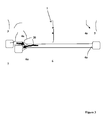
figure 5 qui montre un dispositif selon un second mode de réalisation, chaque canalisation 4 et 6 comporte au voisinage de chacune de ses extrémités 4a, 4b, 6a, 6b un clapet 30. Ce clapet 30 comporte une languette ressort 30 solidaire, au niveau d'un de ses bords, de l'intérieur d'un collecteur 3, 7 ou 5. - Au repos, la languette 30 est maintenue à distance de l'ouverture de chaque canalisation et permet ainsi la circulation du fluide 20 entre canalisations 4 et 6 et collecteurs 3, 7 et 5.
- L'Homme du Métier calibrera les languettes ressorts 30 afin qu'elles ne fléchissent pas sous l'effet du débit normal de circulation du fluide 20 dans le dispositif, mais en permettant la flexion des languettes de manière à ce qu'elles viennent obturer l'extrémité d'une canalisation 4c en cas de rupture accidentelle comme à la
figure 6 . - Cette flexion sera provoquée par la différence de débit locale et momentanée aux extrémités de la canalisation 4c rompue. La flexion sera maintenue par la différence de pression entre l'intérieur du dispositif 1, où le fluide circule sous une pression supérieure à la pression atmosphérique, et la pression atmosphérique externe.
- Ainsi, en cas d'agression du véhicule au niveau du dispositif, celui-ci pourra éviter les fuites de fluide et conserver ses capacités de masquage.
- Il est évident pour l'Homme du Métier que les clapets 30 pourront avoir une structure différente, il suffit qu'elle permette le passage d'un fluide et son arrêt de circulation selon les conditions précédemment énoncées, ainsi un dispositif plus sophistiqué pourra détecter une perte de pression dans une canalisation au moyen par exemple de détecteurs de pression situés dans chaque canalisation. Les clapets comporteront alors des vannes à commande automatique disposées à chaque extrémité des canalisations et pourront alors être actionnées de manière à condamner la circulation de fluide dans la canalisation endommagée.
Claims (9)
- - Dispositif de camouflage (1) infrarouge comportant un réseau de canalisations (4 et 6) parallèles transportant un fluide caloporteur (20) destiné à modifier la signature thermique d'un véhicule, dispositif (1) caractérisé en ce qu'il comporte un collecteur d'amenée (3) au niveau duquel le fluide caloporteur (20) rentre dans le dispositif (1) pour être acheminé vers un collecteur intermédiaire (5) au moyen d'une première série de premières canalisations (4) solidaires du collecteur d'amenée (3) par leur première extrémité (4a) et du collecteur intermédiaire (5) par leur seconde extrémité (4b), une seconde série (6) de secondes canalisations (6a) achemine le fluide caloporteur (20) du collecteur intermédiaire (5) vers un collecteur de sortie (7) destiné à évacuer le fluide (20) hors du dispositif (1), secondes canalisations (6) qui sont solidaires du collecteur intermédiaire (5) par leur première extrémité (6a) et du collecteur de sortie (7) par leur seconde extrémité (6b), chaque première canalisation (4) étant située au voisinage d'une seconde canalisation (6) de manière à former au niveau du dispositif (1) une alternance de premières (4) et secondes (6) canalisations parallèles, le collecteur (3) d'amenée et le collecteur de sortie (5) étant voisins l'un de l'autre.
- - Dispositif de camouflage (1) infrarouge selon la revendication 1, caractérisé en ce que la distribution des canalisations (4,6) et des collecteurs (3,5,7) sensiblement dans un même plan permet de donner au dispositif (1) la forme d'un panneau.
- - Dispositif de camouflage (1) infrarouge selon une des revendications 1 ou 2, caractérisé en ce que les canalisations (4,6) et collecteurs (3,5,7) sont noyés dans un substrat (8) homogénéisant la signature thermique du dispositif (1).
- - Dispositif de camouflage (1) infrarouge selon la revendication 3, caractérisé en ce que le substrat (8) comporte deux parois (9,10) entre lesquelles se situent les canalisations (4,6), la première paroi (9) est destinée à être orientée vers une face externe (101) du véhicule (100) et comporte un matériau favorisant l'isolation thermique, un film réfléchissant (11) à faible émissivité thermique est disposé sur la face de cette paroi (9) destinée à être orientée vers le véhicule, la seconde paroi (10) comporte un matériau favorisant la conduction thermique et la face de cette seconde paroi (10) qui est orientée vers l'extérieur du véhicule comporte un film métallique (13) conducteur.
- - Dispositif de camouflage (1) infrarouge selon la revendication 4, caractérisé en ce que le matériau de la première paroi (9) favorisant l'isolation thermique comporte de la mousse de polyuréthane.
- - Dispositif de camouflage infrarouge selon la revendication 4, caractérisé en ce que le matériau de la seconde paroi (10) favorisant la conduction thermique comporte un alliage d'aluminium.
- - Dispositif de camouflage infrarouge selon une des revendications 1 à 6, caractérisé en ce que chaque extrémité (4a,4b,6a,6b) de chaque canalisation (4,6) comporte un clapet (30) taré de manière à obturer la canalisation (4,6) en cas de rupture de celle-ci.
- - Dispositif de camouflage (1) infrarouge selon la revendication 7, caractérisé en ce que chaque clapet (30) comporte une lamelle ressort (30) située dans un collecteur (3,5,7) et solidaire par un de ses bords du voisinage de l'extrémité (4a,4b,6a,6b) de la canalisation (4,6) à obturer.
- - Véhicule militaire (100) comportant au moins un dispositif de camouflage thermique (1) selon une des revendications précédentes et un moyen de régulation thermique d'un fluide caloporteur (20) et de circulation de ce fluide (20), moyen de régulation thermique et de circulation connectés au dispositif de camouflage thermique qui est disposé sur au moins une face externe (101) du véhicule (100).
Priority Applications (1)
| Application Number | Priority Date | Filing Date | Title |
|---|---|---|---|
| SI201530087T SI3015813T1 (sl) | 2014-10-30 | 2015-10-28 | Toplotna kamuflažna razporeditev in vozilo, ki vključuje tovrstno napravo |
Applications Claiming Priority (1)
| Application Number | Priority Date | Filing Date | Title |
|---|---|---|---|
| FR1402477A FR3028025B1 (fr) | 2014-10-30 | 2014-10-30 | Dispositif de camouflage thermique et vehicule comportant un tel dispositif |
Publications (2)
| Publication Number | Publication Date |
|---|---|
| EP3015813A1 true EP3015813A1 (fr) | 2016-05-04 |
| EP3015813B1 EP3015813B1 (fr) | 2017-07-12 |
Family
ID=52589438
Family Applications (1)
| Application Number | Title | Priority Date | Filing Date |
|---|---|---|---|
| EP15191991.7A Active EP3015813B1 (fr) | 2014-10-30 | 2015-10-28 | Dispositif de camouflage thermique et vehicule comportant un tel dispositif |
Country Status (8)
| Country | Link |
|---|---|
| US (1) | US10345080B2 (fr) |
| EP (1) | EP3015813B1 (fr) |
| BR (1) | BR102015027360B1 (fr) |
| CA (1) | CA2908099C (fr) |
| DK (1) | DK3015813T3 (fr) |
| FR (1) | FR3028025B1 (fr) |
| IL (1) | IL242090B (fr) |
| SI (1) | SI3015813T1 (fr) |
Cited By (3)
| Publication number | Priority date | Publication date | Assignee | Title |
|---|---|---|---|---|
| CN106931832A (zh) * | 2017-04-11 | 2017-07-07 | 江苏豪赛科技股份有限公司 | 地面有内热源装备高温孔口的红外抑制结构 |
| RU2673859C1 (ru) * | 2017-09-18 | 2018-11-30 | Федеральное Государственное Казенное "Военное Образовательное Учреждение Высшего Образования "Военный Учебно-Научный Центр Сухопутных Войск "Общевойсковая Академия Вооруженных Сил Российской Федерации" | Устройство снижения тепловой заметности боевых машин |
| RU2802967C1 (ru) * | 2023-02-17 | 2023-09-05 | Дмитрий Николаевич Репин | Силовая установка с улучшенными процессами отведения картерных газов, выпуска отработавших газов и пылеудаления, снижающая инфракрасную заметность военной гусеничной машины |
Families Citing this family (4)
| Publication number | Priority date | Publication date | Assignee | Title |
|---|---|---|---|---|
| RU184679U1 (ru) * | 2018-07-24 | 2018-11-02 | Федеральное Государственное Казенное Военное Образовательное Учреждение Высшего Образования Военный Учебно-Научный Центр Сухопутных Войск "Общевойсковая Академия Вооруженных Сил Российской Федерации" | Защитно-маскировочный экран комбинированного охлаждения теплового излучения нагретых частей наземного подвижного объекта |
| RU193769U1 (ru) * | 2019-06-14 | 2019-11-14 | Федеральное Государственное Казенное Военное Образовательное Учреждение Высшего Образования Военный Учебно-Научный Центр Сухопутных Войск "Общевойсковая Академия Вооруженных Сил Российской Федерации" | Защитно-маскировочный экран комбинированного охлаждения теплового излучения нагретых частей крупногабаритного наземного подвижного электроагрегата |
| PL249153B1 (pl) * | 2022-11-29 | 2026-03-02 | Wojskowy Inst Techniki Inzynieryjnej Im Profesora Jozefa Kosackiego | Urządzenie maskowania optycznego i termalnego |
| CN119148792B (zh) * | 2024-09-03 | 2025-05-27 | 哈尔滨工程大学 | 一种适用于复杂非受控环境下动态热伪装系统 |
Citations (3)
| Publication number | Priority date | Publication date | Assignee | Title |
|---|---|---|---|---|
| DE29519417U1 (de) * | 1994-12-07 | 1996-06-05 | Vogel & Noot Wärmetechnik AG, Wartberg | Heizkörper mit im wesentlichen rohrartiger Zuführung und Abführung für ein Wärmeträgerfluid |
| US5751006A (en) | 1997-05-05 | 1998-05-12 | The United States Of America As Represented By The Secretary Of The Navy | Water heated panels for simulating the infrared signature of a target |
| WO2002043445A2 (fr) * | 2000-10-11 | 2002-05-30 | Tvi Corporation | Systeme d'identification d'images thermiques |
Family Cites Families (5)
| Publication number | Priority date | Publication date | Assignee | Title |
|---|---|---|---|---|
| DE3433598A1 (de) * | 1984-09-13 | 1986-03-20 | Heinz Schilling KG, 4152 Kempen | Verfahren zur praktischen anwendung des gegenstromprinzips fuer waermeaustauscher, luft/wasser, luft/luft oder sinngemaess fuer andere medien |
| US4825937A (en) * | 1988-07-12 | 1989-05-02 | Kertzman Harvey Z | Sealing apparatus for automobile radiators |
| NL1022998C2 (nl) * | 2003-03-24 | 2004-09-27 | Finhoeks B V | Mobiele warmtewisselaar en systeem voor het verschaffen van een ijsbaan voorzien van een dergelijke warmtewisselaar. |
| DE102004037419B3 (de) * | 2004-07-30 | 2006-02-16 | Siemens Ag | Ventil für den Einsatz in einer kraftstoffführenden Leitung eines Kraftfahrzeuges |
| DE102012105446B4 (de) * | 2011-07-26 | 2018-07-26 | Endress+Hauser Conducta Gmbh+Co. Kg | Vorrichtung zur Bestimmung und/oder Überwachung einer chemischen oder physikalischen Prozessgröße in der Automatisierungstechnik |
-
2014
- 2014-10-30 FR FR1402477A patent/FR3028025B1/fr active Active
-
2015
- 2015-10-02 CA CA2908099A patent/CA2908099C/fr active Active
- 2015-10-15 IL IL242090A patent/IL242090B/en active IP Right Grant
- 2015-10-27 US US14/924,175 patent/US10345080B2/en active Active
- 2015-10-28 EP EP15191991.7A patent/EP3015813B1/fr active Active
- 2015-10-28 BR BR102015027360-6A patent/BR102015027360B1/pt active IP Right Grant
- 2015-10-28 SI SI201530087T patent/SI3015813T1/sl unknown
- 2015-10-28 DK DK15191991.7T patent/DK3015813T3/en active
Patent Citations (3)
| Publication number | Priority date | Publication date | Assignee | Title |
|---|---|---|---|---|
| DE29519417U1 (de) * | 1994-12-07 | 1996-06-05 | Vogel & Noot Wärmetechnik AG, Wartberg | Heizkörper mit im wesentlichen rohrartiger Zuführung und Abführung für ein Wärmeträgerfluid |
| US5751006A (en) | 1997-05-05 | 1998-05-12 | The United States Of America As Represented By The Secretary Of The Navy | Water heated panels for simulating the infrared signature of a target |
| WO2002043445A2 (fr) * | 2000-10-11 | 2002-05-30 | Tvi Corporation | Systeme d'identification d'images thermiques |
Cited By (4)
| Publication number | Priority date | Publication date | Assignee | Title |
|---|---|---|---|---|
| CN106931832A (zh) * | 2017-04-11 | 2017-07-07 | 江苏豪赛科技股份有限公司 | 地面有内热源装备高温孔口的红外抑制结构 |
| CN106931832B (zh) * | 2017-04-11 | 2018-11-23 | 江苏豪赛科技股份有限公司 | 地面有内热源装备高温孔口的红外抑制结构 |
| RU2673859C1 (ru) * | 2017-09-18 | 2018-11-30 | Федеральное Государственное Казенное "Военное Образовательное Учреждение Высшего Образования "Военный Учебно-Научный Центр Сухопутных Войск "Общевойсковая Академия Вооруженных Сил Российской Федерации" | Устройство снижения тепловой заметности боевых машин |
| RU2802967C1 (ru) * | 2023-02-17 | 2023-09-05 | Дмитрий Николаевич Репин | Силовая установка с улучшенными процессами отведения картерных газов, выпуска отработавших газов и пылеудаления, снижающая инфракрасную заметность военной гусеничной машины |
Also Published As
| Publication number | Publication date |
|---|---|
| CA2908099A1 (fr) | 2016-04-30 |
| SI3015813T1 (sl) | 2017-10-30 |
| EP3015813B1 (fr) | 2017-07-12 |
| BR102015027360B1 (pt) | 2021-07-27 |
| US10345080B2 (en) | 2019-07-09 |
| IL242090A0 (en) | 2016-02-29 |
| BR102015027360A2 (pt) | 2016-08-02 |
| FR3028025A1 (fr) | 2016-05-06 |
| FR3028025B1 (fr) | 2016-11-04 |
| IL242090B (en) | 2019-06-30 |
| DK3015813T3 (en) | 2017-10-23 |
| CA2908099C (fr) | 2022-08-30 |
| US20160123706A1 (en) | 2016-05-05 |
Similar Documents
| Publication | Publication Date | Title |
|---|---|---|
| EP3015813B1 (fr) | Dispositif de camouflage thermique et vehicule comportant un tel dispositif | |
| EP3473833B1 (fr) | Système de protection contre le givre pour nacelle de moteur d'aéronef | |
| EP2446197B1 (fr) | Radiateur reversible | |
| US12003214B2 (en) | Heat exchange system | |
| EP2019038B1 (fr) | Dispositif de protection solaire pour instrument spatial | |
| FR2902830A1 (fr) | Turboreacteur pour aeronef | |
| FR2944589A1 (fr) | Dispositif de fixation d'un plenum a une soufflerie | |
| EP1362012B1 (fr) | Dispositif de soufflage d'un fluide sur au moins une face d'un element mince, et unite de soufflage associee | |
| EP1811256A1 (fr) | Installation déchange thermique | |
| BRPI0808399A2 (pt) | Veículo grande | |
| EP1709370B1 (fr) | Capteur solaire thermique a air | |
| FR3048489B1 (fr) | Systeme de ventilation d'un batiment | |
| FR2712380A1 (fr) | Dispositif de climatisation statique. | |
| BE1014988A7 (fr) | Ecran de protection. | |
| FR3084144A1 (fr) | Installation thermique | |
| EP3167231B1 (fr) | Système de refroidissement d'un local par un flux d'air froid puisé sous le plafond | |
| FR3055407A1 (fr) | Dispositif de stockage de liquide pour delivrer de l'eau chaude sanitaire | |
| WO2017109424A1 (fr) | Dispositif de mise en temperature d'un objet | |
| FR3082607A1 (fr) | Chauffe-eau solaire air-eau | |
| FR2646498A1 (fr) | Batterie de conditionnement d'air, destinee a assurer le chauffage ou le refroidissement d'un local | |
| FR2716960A1 (fr) | Faisceau de plaques pour un échangeur thermique. | |
| HK40047032A (en) | Heat exchange system | |
| HK40047032B (en) | Heat exchange system | |
| FR2487958A1 (fr) | Capteur solaire mixte dont la puissance peut indifferemment ou simultanement servir pour le chauffage de gaz ou le chauffage de liquides | |
| FR2887324A1 (fr) | Installation de climatisation, notamment d'allees s'etendant entre deux gondoles refrigerees |
Legal Events
| Date | Code | Title | Description |
|---|---|---|---|
| PUAI | Public reference made under article 153(3) epc to a published international application that has entered the european phase |
Free format text: ORIGINAL CODE: 0009012 |
|
| AK | Designated contracting states |
Kind code of ref document: A1 Designated state(s): AL AT BE BG CH CY CZ DE DK EE ES FI FR GB GR HR HU IE IS IT LI LT LU LV MC MK MT NL NO PL PT RO RS SE SI SK SM TR |
|
| AX | Request for extension of the european patent |
Extension state: BA ME |
|
| 17P | Request for examination filed |
Effective date: 20161028 |
|
| RBV | Designated contracting states (corrected) |
Designated state(s): AL AT BE BG CH CY CZ DE DK EE ES FI FR GB GR HR HU IE IS IT LI LT LU LV MC MK MT NL NO PL PT RO RS SE SI SK SM TR |
|
| GRAJ | Information related to disapproval of communication of intention to grant by the applicant or resumption of examination proceedings by the epo deleted |
Free format text: ORIGINAL CODE: EPIDOSDIGR1 |
|
| GRAP | Despatch of communication of intention to grant a patent |
Free format text: ORIGINAL CODE: EPIDOSNIGR1 |
|
| RIC1 | Information provided on ipc code assigned before grant |
Ipc: F28F 13/18 20060101ALI20170215BHEP Ipc: F28D 1/053 20060101ALI20170215BHEP Ipc: F28F 11/06 20060101ALI20170215BHEP Ipc: F41H 3/00 20060101AFI20170215BHEP |
|
| INTG | Intention to grant announced |
Effective date: 20170227 |
|
| GRAS | Grant fee paid |
Free format text: ORIGINAL CODE: EPIDOSNIGR3 |
|
| GRAA | (expected) grant |
Free format text: ORIGINAL CODE: 0009210 |
|
| AK | Designated contracting states |
Kind code of ref document: B1 Designated state(s): AL AT BE BG CH CY CZ DE DK EE ES FI FR GB GR HR HU IE IS IT LI LT LU LV MC MK MT NL NO PL PT RO RS SE SI SK SM TR |
|
| REG | Reference to a national code |
Ref country code: GB Ref legal event code: FG4D Free format text: NOT ENGLISH |
|
| REG | Reference to a national code |
Ref country code: CH Ref legal event code: EP |
|
| REG | Reference to a national code |
Ref country code: AT Ref legal event code: REF Ref document number: 908760 Country of ref document: AT Kind code of ref document: T Effective date: 20170715 |
|
| REG | Reference to a national code |
Ref country code: IE Ref legal event code: FG4D Free format text: LANGUAGE OF EP DOCUMENT: FRENCH |
|
| REG | Reference to a national code |
Ref country code: DE Ref legal event code: R096 Ref document number: 602015003539 Country of ref document: DE |
|
| REG | Reference to a national code |
Ref country code: FR Ref legal event code: PLFP Year of fee payment: 3 |
|
| REG | Reference to a national code |
Ref country code: SE Ref legal event code: TRGR |
|
| REG | Reference to a national code |
Ref country code: DK Ref legal event code: T3 Effective date: 20171019 |
|
| REG | Reference to a national code |
Ref country code: NL Ref legal event code: MP Effective date: 20170712 |
|
| REG | Reference to a national code |
Ref country code: LT Ref legal event code: MG4D |
|
| REG | Reference to a national code |
Ref country code: AT Ref legal event code: MK05 Ref document number: 908760 Country of ref document: AT Kind code of ref document: T Effective date: 20170712 |
|
| PG25 | Lapsed in a contracting state [announced via postgrant information from national office to epo] |
Ref country code: NL Free format text: LAPSE BECAUSE OF FAILURE TO SUBMIT A TRANSLATION OF THE DESCRIPTION OR TO PAY THE FEE WITHIN THE PRESCRIBED TIME-LIMIT Effective date: 20170712 Ref country code: AT Free format text: LAPSE BECAUSE OF FAILURE TO SUBMIT A TRANSLATION OF THE DESCRIPTION OR TO PAY THE FEE WITHIN THE PRESCRIBED TIME-LIMIT Effective date: 20170712 Ref country code: HR Free format text: LAPSE BECAUSE OF FAILURE TO SUBMIT A TRANSLATION OF THE DESCRIPTION OR TO PAY THE FEE WITHIN THE PRESCRIBED TIME-LIMIT Effective date: 20170712 Ref country code: LT Free format text: LAPSE BECAUSE OF FAILURE TO SUBMIT A TRANSLATION OF THE DESCRIPTION OR TO PAY THE FEE WITHIN THE PRESCRIBED TIME-LIMIT Effective date: 20170712 Ref country code: FI Free format text: LAPSE BECAUSE OF FAILURE TO SUBMIT A TRANSLATION OF THE DESCRIPTION OR TO PAY THE FEE WITHIN THE PRESCRIBED TIME-LIMIT Effective date: 20170712 Ref country code: NO Free format text: LAPSE BECAUSE OF FAILURE TO SUBMIT A TRANSLATION OF THE DESCRIPTION OR TO PAY THE FEE WITHIN THE PRESCRIBED TIME-LIMIT Effective date: 20171012 |
|
| PG25 | Lapsed in a contracting state [announced via postgrant information from national office to epo] |
Ref country code: LV Free format text: LAPSE BECAUSE OF FAILURE TO SUBMIT A TRANSLATION OF THE DESCRIPTION OR TO PAY THE FEE WITHIN THE PRESCRIBED TIME-LIMIT Effective date: 20170712 Ref country code: BG Free format text: LAPSE BECAUSE OF FAILURE TO SUBMIT A TRANSLATION OF THE DESCRIPTION OR TO PAY THE FEE WITHIN THE PRESCRIBED TIME-LIMIT Effective date: 20171012 Ref country code: GR Free format text: LAPSE BECAUSE OF FAILURE TO SUBMIT A TRANSLATION OF THE DESCRIPTION OR TO PAY THE FEE WITHIN THE PRESCRIBED TIME-LIMIT Effective date: 20171013 Ref country code: RS Free format text: LAPSE BECAUSE OF FAILURE TO SUBMIT A TRANSLATION OF THE DESCRIPTION OR TO PAY THE FEE WITHIN THE PRESCRIBED TIME-LIMIT Effective date: 20170712 Ref country code: ES Free format text: LAPSE BECAUSE OF FAILURE TO SUBMIT A TRANSLATION OF THE DESCRIPTION OR TO PAY THE FEE WITHIN THE PRESCRIBED TIME-LIMIT Effective date: 20170712 Ref country code: IS Free format text: LAPSE BECAUSE OF FAILURE TO SUBMIT A TRANSLATION OF THE DESCRIPTION OR TO PAY THE FEE WITHIN THE PRESCRIBED TIME-LIMIT Effective date: 20171112 Ref country code: PL Free format text: LAPSE BECAUSE OF FAILURE TO SUBMIT A TRANSLATION OF THE DESCRIPTION OR TO PAY THE FEE WITHIN THE PRESCRIBED TIME-LIMIT Effective date: 20170712 |
|
| REG | Reference to a national code |
Ref country code: DE Ref legal event code: R097 Ref document number: 602015003539 Country of ref document: DE |
|
| PG25 | Lapsed in a contracting state [announced via postgrant information from national office to epo] |
Ref country code: CZ Free format text: LAPSE BECAUSE OF FAILURE TO SUBMIT A TRANSLATION OF THE DESCRIPTION OR TO PAY THE FEE WITHIN THE PRESCRIBED TIME-LIMIT Effective date: 20170712 Ref country code: RO Free format text: LAPSE BECAUSE OF FAILURE TO SUBMIT A TRANSLATION OF THE DESCRIPTION OR TO PAY THE FEE WITHIN THE PRESCRIBED TIME-LIMIT Effective date: 20170712 |
|
| PLBE | No opposition filed within time limit |
Free format text: ORIGINAL CODE: 0009261 |
|
| STAA | Information on the status of an ep patent application or granted ep patent |
Free format text: STATUS: NO OPPOSITION FILED WITHIN TIME LIMIT |
|
| PG25 | Lapsed in a contracting state [announced via postgrant information from national office to epo] |
Ref country code: EE Free format text: LAPSE BECAUSE OF FAILURE TO SUBMIT A TRANSLATION OF THE DESCRIPTION OR TO PAY THE FEE WITHIN THE PRESCRIBED TIME-LIMIT Effective date: 20170712 Ref country code: SM Free format text: LAPSE BECAUSE OF FAILURE TO SUBMIT A TRANSLATION OF THE DESCRIPTION OR TO PAY THE FEE WITHIN THE PRESCRIBED TIME-LIMIT Effective date: 20170712 Ref country code: MC Free format text: LAPSE BECAUSE OF FAILURE TO SUBMIT A TRANSLATION OF THE DESCRIPTION OR TO PAY THE FEE WITHIN THE PRESCRIBED TIME-LIMIT Effective date: 20170712 Ref country code: SK Free format text: LAPSE BECAUSE OF FAILURE TO SUBMIT A TRANSLATION OF THE DESCRIPTION OR TO PAY THE FEE WITHIN THE PRESCRIBED TIME-LIMIT Effective date: 20170712 Ref country code: IT Free format text: LAPSE BECAUSE OF FAILURE TO SUBMIT A TRANSLATION OF THE DESCRIPTION OR TO PAY THE FEE WITHIN THE PRESCRIBED TIME-LIMIT Effective date: 20170712 |
|
| 26N | No opposition filed |
Effective date: 20180413 |
|
| REG | Reference to a national code |
Ref country code: IE Ref legal event code: MM4A |
|
| PG25 | Lapsed in a contracting state [announced via postgrant information from national office to epo] |
Ref country code: LU Free format text: LAPSE BECAUSE OF NON-PAYMENT OF DUE FEES Effective date: 20171028 |
|
| REG | Reference to a national code |
Ref country code: BE Ref legal event code: MM Effective date: 20171031 |
|
| PG25 | Lapsed in a contracting state [announced via postgrant information from national office to epo] |
Ref country code: BE Free format text: LAPSE BECAUSE OF NON-PAYMENT OF DUE FEES Effective date: 20171031 |
|
| REG | Reference to a national code |
Ref country code: FR Ref legal event code: PLFP Year of fee payment: 4 |
|
| PG25 | Lapsed in a contracting state [announced via postgrant information from national office to epo] |
Ref country code: MT Free format text: LAPSE BECAUSE OF FAILURE TO SUBMIT A TRANSLATION OF THE DESCRIPTION OR TO PAY THE FEE WITHIN THE PRESCRIBED TIME-LIMIT Effective date: 20170712 |
|
| PG25 | Lapsed in a contracting state [announced via postgrant information from national office to epo] |
Ref country code: IE Free format text: LAPSE BECAUSE OF NON-PAYMENT OF DUE FEES Effective date: 20171028 |
|
| REG | Reference to a national code |
Ref country code: CH Ref legal event code: PL |
|
| PG25 | Lapsed in a contracting state [announced via postgrant information from national office to epo] |
Ref country code: HU Free format text: LAPSE BECAUSE OF FAILURE TO SUBMIT A TRANSLATION OF THE DESCRIPTION OR TO PAY THE FEE WITHIN THE PRESCRIBED TIME-LIMIT; INVALID AB INITIO Effective date: 20151028 |
|
| PG25 | Lapsed in a contracting state [announced via postgrant information from national office to epo] |
Ref country code: CH Free format text: LAPSE BECAUSE OF NON-PAYMENT OF DUE FEES Effective date: 20181031 Ref country code: LI Free format text: LAPSE BECAUSE OF NON-PAYMENT OF DUE FEES Effective date: 20181031 |
|
| PG25 | Lapsed in a contracting state [announced via postgrant information from national office to epo] |
Ref country code: CY Free format text: LAPSE BECAUSE OF FAILURE TO SUBMIT A TRANSLATION OF THE DESCRIPTION OR TO PAY THE FEE WITHIN THE PRESCRIBED TIME-LIMIT Effective date: 20170712 |
|
| PG25 | Lapsed in a contracting state [announced via postgrant information from national office to epo] |
Ref country code: MK Free format text: LAPSE BECAUSE OF FAILURE TO SUBMIT A TRANSLATION OF THE DESCRIPTION OR TO PAY THE FEE WITHIN THE PRESCRIBED TIME-LIMIT Effective date: 20170712 |
|
| PG25 | Lapsed in a contracting state [announced via postgrant information from national office to epo] |
Ref country code: TR Free format text: LAPSE BECAUSE OF FAILURE TO SUBMIT A TRANSLATION OF THE DESCRIPTION OR TO PAY THE FEE WITHIN THE PRESCRIBED TIME-LIMIT Effective date: 20170712 |
|
| PG25 | Lapsed in a contracting state [announced via postgrant information from national office to epo] |
Ref country code: PT Free format text: LAPSE BECAUSE OF FAILURE TO SUBMIT A TRANSLATION OF THE DESCRIPTION OR TO PAY THE FEE WITHIN THE PRESCRIBED TIME-LIMIT Effective date: 20170712 |
|
| PG25 | Lapsed in a contracting state [announced via postgrant information from national office to epo] |
Ref country code: AL Free format text: LAPSE BECAUSE OF FAILURE TO SUBMIT A TRANSLATION OF THE DESCRIPTION OR TO PAY THE FEE WITHIN THE PRESCRIBED TIME-LIMIT Effective date: 20170712 |
|
| PGFP | Annual fee paid to national office [announced via postgrant information from national office to epo] |
Ref country code: DK Payment date: 20250923 Year of fee payment: 11 |
|
| PGFP | Annual fee paid to national office [announced via postgrant information from national office to epo] |
Ref country code: GB Payment date: 20250923 Year of fee payment: 11 |
|
| PGFP | Annual fee paid to national office [announced via postgrant information from national office to epo] |
Ref country code: FR Payment date: 20250923 Year of fee payment: 11 |
|
| PGFP | Annual fee paid to national office [announced via postgrant information from national office to epo] |
Ref country code: SE Payment date: 20250923 Year of fee payment: 11 |
|
| PGFP | Annual fee paid to national office [announced via postgrant information from national office to epo] |
Ref country code: SI Payment date: 20250930 Year of fee payment: 11 |
|
| PGFP | Annual fee paid to national office [announced via postgrant information from national office to epo] |
Ref country code: DE Payment date: 20250923 Year of fee payment: 11 |