EP3015783A2 - Air conditioner - Google Patents
Air conditioner Download PDFInfo
- Publication number
- EP3015783A2 EP3015783A2 EP15189303.9A EP15189303A EP3015783A2 EP 3015783 A2 EP3015783 A2 EP 3015783A2 EP 15189303 A EP15189303 A EP 15189303A EP 3015783 A2 EP3015783 A2 EP 3015783A2
- Authority
- EP
- European Patent Office
- Prior art keywords
- panel
- crosspiece
- air conditioner
- suction panel
- opening section
- Prior art date
- Legal status (The legal status is an assumption and is not a legal conclusion. Google has not performed a legal analysis and makes no representation as to the accuracy of the status listed.)
- Withdrawn
Links
- 230000000149 penetrating effect Effects 0.000 claims description 5
- 238000004378 air conditioning Methods 0.000 description 8
- 230000000694 effects Effects 0.000 description 1
- 238000009434 installation Methods 0.000 description 1
- 125000006850 spacer group Chemical group 0.000 description 1
Images


Classifications
-
- F—MECHANICAL ENGINEERING; LIGHTING; HEATING; WEAPONS; BLASTING
- F24—HEATING; RANGES; VENTILATING
- F24F—AIR-CONDITIONING; AIR-HUMIDIFICATION; VENTILATION; USE OF AIR CURRENTS FOR SCREENING
- F24F13/00—Details common to, or for air-conditioning, air-humidification, ventilation or use of air currents for screening
- F24F13/20—Casings or covers
-
- F—MECHANICAL ENGINEERING; LIGHTING; HEATING; WEAPONS; BLASTING
- F24—HEATING; RANGES; VENTILATING
- F24F—AIR-CONDITIONING; AIR-HUMIDIFICATION; VENTILATION; USE OF AIR CURRENTS FOR SCREENING
- F24F1/00—Room units for air-conditioning, e.g. separate or self-contained units or units receiving primary air from a central station
- F24F1/0007—Indoor units, e.g. fan coil units
- F24F1/0043—Indoor units, e.g. fan coil units characterised by mounting arrangements
- F24F1/0057—Indoor units, e.g. fan coil units characterised by mounting arrangements mounted in or on a wall
Definitions
- the present invention relates to an indoor unit of an air conditioner.
- an air conditioner which accommodates a blower, a heat exchanger or the like inside a housing, and performs the indoor air-conditioning by ejecting the indoor air after sucking the air to perform the adjustment of the temperature and the humidity is known.
- An example of such an air conditioner is disclosed in
- Patent Literature 1 1
- a front panel and a suction panel are provided to cover the front surface.
- a suction port is provided above the suction panel and the front panel, and the air is sucked into the housing via the suction port.
- the present invention provides an air conditioner which can limit the deformation of the suction panel when the suction panel is pressed using a simple structure.
- An air conditioner includes a front panel in which a crosspiece is provided on a front side of a front opening section of a housing in a horizontal direction when the air conditioner is installed in a intersecting direction intersecting with a penetrating direction in which the front opening section penetrate; a suction panel disposed opposite to the crosspiece to cover the front opening section and the front panel and provided to allow opening and closing of the front opening section; and a plurality of ribs provided at intervals in the intersecting direction on one of a back surfaces of the suction panel and a facing surface to the suction panel of the crosspiece which face each other, projecting toward the other, and having tips coming into contact with the other.
- An air conditioner includes a front panel in which a crosspiece is provided on a front side of a front opening section of a housing in a horizontal direction when the air conditioner is installed in a intersecting direction intersecting with a penetrating direction in which the front opening section penetrate; a suction panel disposed opposite to the crosspiece to cover the front opening section and the front panel, and provided to allow opening and closing of the front opening section; and a plurality of ribs provided at intervals in the intersecting direction on a back surfaces of the suction panel and a facing surface to the suction panel of the crosspiece which face each other, wherein the ribs provided on the back surface of the suction panel protrude toward the facing surface of the crosspiece, tips thereof come into contact with the facing surface of the crosspiece, the ribs formed on the facing surface of the crosspiece protrude toward the back surface of the suction panel, and the tips thereof come into contact with the back surface of the suction panel.
- the crosspiece is provided on the front panel, and the crosspiece and the suction panel come into contact with each other via the ribs. Therefore, when the suction panel is pressed, it is not bent due to the gap between the suction panel and the crosspiece. Moreover, even if the suction panel is relatively moved so as to be shifted with respect to the crosspiece, since the suction panel and the crosspiece come into contact with each other via the ribs, it is possible to reduce the contact area between the suction panel and the crosspiece. Therefore, it is possible to limit the rubbing sound generated during the relative movement, and the damage of the suction panel and the crosspiece.
- the air conditioner in the first or second aspect may further include a top panel configured to cover a top opening section of the housing and provided continuously on the front panel, wherein the top panel has a plurality of horizontal frames extending in the intersecting direction and a plurality of vertical frames intersecting with the horizontal frames and has a grid shape, and the plurality of vertical frames are connected to the crosspiece.
- the vertical frames of the top panel assembled in a grid shape by the horizontal frames and the vertical frames are connected to the crosspiece, when a pressing force is applied to the crosspiece from the suction panel via the ribs, the pressing force is transmitted to the vertical frames of the top panel, and thus, it is possible to limit the deformation of the crosspiece. Therefore, it is possible to further limit the flexure of the suction panel when the suction panel is pressed.
- the ribs of the third aspect may be provided at positions corresponding to positions at which the vertical frames are connected to the crosspiece.
- the ribs are formed at such positions, when the pressing force is applied to the crosspiece from the suction panel via the ribs, the pressing force is directly transmitted to the vertical frame of the top panel, and thus, it is possible to further limit the deformation of the crosspiece. Therefore, it is possible to further limit the flexure of the suction panel when the suction panel is pressed.
- the suction panel of the first to fourth aspects may have a panel main body which covers the front opening section, and a plurality of support sections which are provided at an upper end portion of the panel main body to be spaced apart from each other in the intersecting direction, and fix the panel main body with respect to the front panel, wherein the ribs are disposed at least in a region separated farthest from the plurality of support sections in the intersecting direction.
- the ribs are disposed in a region spaced farthest from the support sections provided on the suction panel and located between the support sections, when there is no rib, the ribs are disposed in a region in which the flexure deformation is the most likely to occur in the suction panel. Therefore, it is possible to effectively limit the flexure of the suction panel when the suction panel is pressed.
- the air conditioner it is possible to limit the deformation of the suction panel when the suction panel is pressed, by a simple structure.
- the air conditioner 1 is an indoor unit provided indoors, and is a device that discharges an air A after sucking the air A and adjusting the temperature and humidity to perform the air-conditioning of the room.
- the air conditioner 1 is equipped with a housing 2 which has an oblong rectangular parallelepiped shape in a direction which is a horizontal direction when the air conditioner 1 is installed, and an air conditioning device 5 accommodated in the housing 2.
- a direction as the horizontal direction when the air conditioner 1 is installed is set as a lateral direction
- a direction as the vertical direction when the air conditioner 1 is installed is simply set as a vertical direction
- a direction perpendicular to the lateral direction and the vertical direction is set as a longitudinal direction.
- a front side of the air conditioner 1 when the air conditioner 1 is installed is a longitudinal front side.
- a heat exchanger 6 As the air conditioning device 5, a heat exchanger 6, a blower fan 7 provided so as to be covered by the heat exchanger 6, a filter 8 provided in the suction port for sucking an air A, a control box 9 provided on one end side in the lateral direction to control the air-conditioning are mainly provided (see Fig. 3 ).
- the housing 2 is equipped with a front panel 16 disposed on the front side as the front side of the air conditioner 1 when the air conditioner 1 is installed, a top panel 20 integrally connected to the front panel 16 and disposed at the top when the air conditioner is installed, and a housing main body 10 which defines a space S (see Fig. 3 ) which accommodates the air conditioning device 5 in the interior thereof along with the front panel 16 and the top panel 20.
- the housing 2 is equipped with a suction panel 25 which covers the front panel 16 from the front, and ribs 26 formed on the suction panel 25.
- the housing main body 10 has a pair of side panels 12 disposed in the lateral direction, a back panel 11 integrally connected to the pair of side panels 12 to face the installation surface, and a bottom panel 13 which supports the pair of side panels 12 and the back panel 11 and is disposed at the bottom.
- the housing main body 10 defines a space S which accommodates the air conditioning device 5 surrounded by the pair of side panels 12, the back panel 11 and the bottom panel 13.
- the space S is opened forward and upward. That is, the housing main body 10 is formed with a front opening section OP1 that laterally penetrates through the housing 2, and a top opening section OP2 that vertically penetrates through the housing 2.
- the front panel 16 is provided integrally with the housing main body 10 on the front side of the front opening section OP1.
- the front panel 16 has a plurality of front vertical frames 17 which extend upward from the bottom panel 13 to be spaced apart from each other in the lateral direction, a crosspiece 18 which is connected to the front vertical frames 17 on the upper side of the front opening section OP1, is formed to extend in the lateral direction (a direction intersecting with the penetrating direction of the front opening section OP1) and is connected to the pair of side panels 12, and a front horizontal frame 19 which laterally connects the front vertical frames 17 below the crosspiece 18.
- the front panel 16 has a grid shape.
- front vertical frame 17 located substantially at the center in the lateral direction is a front vertical frame 17A which is formed to have a larger lateral width dimension than the other front vertical frames 17.
- the top panel 20 is provided integrally with the housing main body 10 on the upper surface side of the top opening section OP2, has a plurality of longitudinally extending vertical frames 21, and a plurality of horizontal frames 22 extending in the lateral direction to intersect with the vertical frames 21, and has a grid shape.
- Each of the vertical frames 21 is disposed spaced apart from each other in the lateral direction, and each of the vertical frames 21 is connected to the crosspiece 18 of the front panel 16 and the back panel 11.
- each of the horizontal frames 22 is disposed to be parallel to the crosspiece 18 to be spaced apart from each other in the longitudinal direction, and is connected to the pair of side panels 12.
- the air A is taken into the space S of the housing 2 from the top opening section OP2.
- the suction panel 25 is disposed on the further front side of the front panel 16 to cover the front opening section OP1 and the front panel 16, and is disposed to face the crosspiece 18.
- the suction panel 25 is able to open and close the front opening section OP1 by being attachable to and detachable from the housing main body 10.
- the suction panel 25 of this embodiment has a panel main body 28 which covers the front opening section OP1 and the front panel 16, and a plurality of support sections 29 which are provided on the upper end portion of the panel main body 28 to be spaced apart from each other in the lateral direction, and fix the panel main body 28 to the front panel 16.
- the panel main body 28 has a plate shape in which a back surface 28a is disposed to face the crosspiece 18 of the front panel 16.
- the support sections 29 are protrusions provided at both lateral end portions and the center portion at the upper end portion of the back surface 28a of the panel main body 28.
- the support sections 29A provided at the both end portions are inserted into receiving holes 12a formed in each of the pair of side panels 12 so as to be recessed rearward from the front.
- the support section 29B provided in the center portion comes into contact with the front vertical frame 17A located substantially at the center in the lateral direction.
- a plurality of protrusions 27 are formed at the lower end portion of the panel main body 28 to be spaced apart from each other in the lateral direction.
- the protrusions 27 are engaged with the lower end portion of the front panel 16 to fix the suction panel 25.
- each protrusion 27A at both lateral end portions, and two protrusions 27B spaced apart in the lateral direction between the protrusions 27A are provided.
- the protrusions 27 are disposed at equal intervals in the lateral direction.
- a plurality of the ribs 26 are formed to protrude toward the crosspiece 18 on the back surface 28a of the panel main body 28 of the suction panel 25 to be spaced from each other in the lateral direction, at a position facing the crosspiece 18, in a state in which the suction panel 25 is attached to the housing main body 10 to cover the front opening section OP 1.
- the ribs 26 are formed in a vertically long rod shape in the vertical direction of the suction panel 25.
- some ribs 26 among the plurality of ribs 26 are formed at the lateral positions corresponding to the position at which the vertical frames 21 of the top panel 20 are connected to the crosspiece 18. Furthermore, in this embodiment, the ribs 26 are disposed in regions which include exactly intermediate positions between the support sections 29. That is, rib groups 26A in which the plurality of the ribs 26 are formed are provided in two regions spaced apart from each other in the lateral direction. In other words, the ribs 26 are disposed in the regions spaced farthest from the support section 29 in the lateral direction.
- a gap is formed between the back surface 28a of the panel main body 28 and a facing surface 18a of the crosspiece 18 facing the back surface 28a, and the surface (tip) of the rib 26 comes into contact with the facing surface 18a of the crosspiece 18.
- the rib 26 may not completely come into contact with the facing surface 18a of the crosspiece 18 in a state in which no external force from the front is applied to the suction panel 25, and a minute gap may be formed between the surface of the ribs 26 and the facing surface 18a of the crosspiece 18 in such a state.
- the crosspiece 18 and the suction panel 25 come into contact with each other via the ribs 26.
- a plurality of air conditioners 1 are stacked so that the suction panel 25 in one air conditioner 1 faces the back panel 11 in another air conditioner 1 during transportation or the like in some cases.
- the vertical frame 21 of the top panel 20 is connected to the crosspiece 18, when the pressing force is applied to the crosspiece 18 from the suction panel 25 via the ribs 26, the pressing force is transmitted to the vertical frame 21 of the top panel 20. Therefore, it is possible to limit the deformation of the crosspiece 18, and it is possible to further limit the flexure of the suction panel 25 when the suction panel 25 is pressed.
- the ribs 26 are formed at the positions corresponding to the positions at which the crosspiece 18 and the vertical frames 21 are connected to each other, when the pressing force is applied to the crosspiece 18 from the suction panel 25 via the ribs 26, the pressing force is directly transmitted to the vertical frame 21 of the top panel 20. Therefore, it is possible to further limit the deformation of the crosspiece 18, and it is possible to further limit the flexure of the suction panel 25 when the suction panel 25 is pressed.
- the ribs 26 are disposed in the regions spaced farthest from the support section 29 and located between the support sections 29 provided on the suction panel 25, when there is no rib 26, the ribs 26 are disposed at positions at which the flexure deformation is most likely to occur in the suction panels 25. Therefore, it is possible to effectively limit the flexure of the suction panel 25 when the suction panel 25 is pressed.
- the air conditioner 1 of this embodiment by forming the ribs 26 facing the crosspiece 18 in the suction panel 25, it is possible to limit the deformation of the suction panel 25 when the suction panel 25 is pressed, by a simple structure.
- the ribs 26 may be formed on the crosspiece 18, and may be formed on both the suction panel 25 and the crosspiece 18.
- the ribs 26 may be formed over the entire region in the lateral direction between the support sections 29 and may be formed only in parts of the region in the lateral direction.
- the air conditioner it is possible to limit the deformation of the suction panel when the suction panel is pressed, by a simple structure.
Landscapes
- Engineering & Computer Science (AREA)
- Chemical & Material Sciences (AREA)
- Combustion & Propulsion (AREA)
- Mechanical Engineering (AREA)
- General Engineering & Computer Science (AREA)
- Air Filters, Heat-Exchange Apparatuses, And Housings Of Air-Conditioning Units (AREA)
Abstract
Description
- The present invention relates to an indoor unit of an air conditioner.
- Conventionally, an air conditioner which accommodates a blower, a heat exchanger or the like inside a housing, and performs the indoor air-conditioning by ejecting the indoor air after sucking the air to perform the adjustment of the temperature and the humidity is known. An example of such an air conditioner is disclosed in
- Patent Literature 1.
- Here, in the housing of the air conditioner disclosed in Patent Literature 1, a front panel and a suction panel are provided to cover the front surface. A suction port is provided above the suction panel and the front panel, and the air is sucked into the housing via the suction port.
- Japanese Unexamined Patent Application, First Publication No.
2010-112628 - However, in the conventional air conditioner as disclosed in Patent Literature 1, a gap is formed between the front panel and the suction panel. Thus, for example, when stacking a plurality of air conditioners during transportation or the like, there is a possibility that the suction panel may be deformed by being pressed from the front side. Therefore, in order to avoid deformation of the suction panel, there is a need for treatment such as interposing a separate member such as a spacer between the front panel and the suction panel. Thus, there is a problem that the labor may be increased.
- The present invention provides an air conditioner which can limit the deformation of the suction panel when the suction panel is pressed using a simple structure.
- An air conditioner according to a first aspect of the invention includes a front panel in which a crosspiece is provided on a front side of a front opening section of a housing in a horizontal direction when the air conditioner is installed in a intersecting direction intersecting with a penetrating direction in which the front opening section penetrate; a suction panel disposed opposite to the crosspiece to cover the front opening section and the front panel and provided to allow opening and closing of the front opening section; and a plurality of ribs provided at intervals in the intersecting direction on one of a back surfaces of the suction panel and a facing surface to the suction panel of the crosspiece which face each other, projecting toward the other, and having tips coming into contact with the other.
- An air conditioner according to a second aspect of the invention includes a front panel in which a crosspiece is provided on a front side of a front opening section of a housing in a horizontal direction when the air conditioner is installed in a intersecting direction intersecting with a penetrating direction in which the front opening section penetrate; a suction panel disposed opposite to the crosspiece to cover the front opening section and the front panel, and provided to allow opening and closing of the front opening section; and a plurality of ribs provided at intervals in the intersecting direction on a back surfaces of the suction panel and a facing surface to the suction panel of the crosspiece which face each other, wherein the ribs provided on the back surface of the suction panel protrude toward the facing surface of the crosspiece, tips thereof come into contact with the facing surface of the crosspiece, the ribs formed on the facing surface of the crosspiece protrude toward the back surface of the suction panel, and the tips thereof come into contact with the back surface of the suction panel.
- According to such an air conditioner, the crosspiece is provided on the front panel, and the crosspiece and the suction panel come into contact with each other via the ribs. Therefore, when the suction panel is pressed, it is not bent due to the gap between the suction panel and the crosspiece. Moreover, even if the suction panel is relatively moved so as to be shifted with respect to the crosspiece, since the suction panel and the crosspiece come into contact with each other via the ribs, it is possible to reduce the contact area between the suction panel and the crosspiece. Therefore, it is possible to limit the rubbing sound generated during the relative movement, and the damage of the suction panel and the crosspiece.
- In the air conditioner according to a third aspect of the present invention, the air conditioner in the first or second aspect may further include a top panel configured to cover a top opening section of the housing and provided continuously on the front panel,
wherein the top panel has a plurality of horizontal frames extending in the intersecting direction and a plurality of vertical frames intersecting with the horizontal frames and has a grid shape, and the plurality of vertical frames are connected to the crosspiece. - Thus, since the vertical frames of the top panel assembled in a grid shape by the horizontal frames and the vertical frames are connected to the crosspiece, when a pressing force is applied to the crosspiece from the suction panel via the ribs, the pressing force is transmitted to the vertical frames of the top panel, and thus, it is possible to limit the deformation of the crosspiece. Therefore, it is possible to further limit the flexure of the suction panel when the suction panel is pressed.
- Further, in the air conditioner according to a fourth aspect of the present invention, the ribs of the third aspect may be provided at positions corresponding to positions at which the vertical frames are connected to the crosspiece.
- Since the ribs are formed at such positions, when the pressing force is applied to the crosspiece from the suction panel via the ribs, the pressing force is directly transmitted to the vertical frame of the top panel, and thus, it is possible to further limit the deformation of the crosspiece. Therefore, it is possible to further limit the flexure of the suction panel when the suction panel is pressed.
- In the air conditioner according to a fifth aspect of the present invention, the suction panel of the first to fourth aspects may have a panel main body which covers the front opening section, and a plurality of support sections which are provided at an upper end portion of the panel main body to be spaced apart from each other in the intersecting direction, and fix the panel main body with respect to the front panel, wherein the ribs are disposed at least in a region separated farthest from the plurality of support sections in the intersecting direction.
- According to such an air conditioner, since the ribs are disposed in a region spaced farthest from the support sections provided on the suction panel and located between the support sections, when there is no rib, the ribs are disposed in a region in which the flexure deformation is the most likely to occur in the suction panel. Therefore, it is possible to effectively limit the flexure of the suction panel when the suction panel is pressed.
- According to the air conditioner, it is possible to limit the deformation of the suction panel when the suction panel is pressed, by a simple structure.
-
-
Fig. 1A is an external perspective view showing an air conditioner according to an embodiment of the present invention and showing a state in which the suction panel is removed. -
Fig. 1B is an external perspective view showing an air conditioner according to the embodiment of the present invention and showing a state in which the suction panel is attached. -
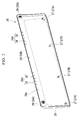
Fig. 2 is a perspective view in which the suction panel of the air conditioner according to the embodiment of the present invention is viewed from the back side. -
Fig. 3 is a cross-sectional view showing a contact state between the suction panel of the air conditioner and the front panel according to the embodiment of the present invention taken from a line A-A ofFig. 1B . - Hereinafter, an air conditioner 1 according to the embodiment of the present invention will be described.
- The air conditioner 1 is an indoor unit provided indoors, and is a device that discharges an air A after sucking the air A and adjusting the temperature and humidity to perform the air-conditioning of the room.
- As shown in
Figs. 1A and 1B , the air conditioner 1 is equipped with ahousing 2 which has an oblong rectangular parallelepiped shape in a direction which is a horizontal direction when the air conditioner 1 is installed, and anair conditioning device 5 accommodated in thehousing 2. - Hereinafter, a direction as the horizontal direction when the air conditioner 1 is installed is set as a lateral direction, a direction as the vertical direction when the air conditioner 1 is installed is simply set as a vertical direction, and a direction perpendicular to the lateral direction and the vertical direction is set as a longitudinal direction. A front side of the air conditioner 1 when the air conditioner 1 is installed is a longitudinal front side.
- As the
air conditioning device 5, aheat exchanger 6, ablower fan 7 provided so as to be covered by theheat exchanger 6, afilter 8 provided in the suction port for sucking an air A, acontrol box 9 provided on one end side in the lateral direction to control the air-conditioning are mainly provided (seeFig. 3 ). - The
housing 2 is equipped with afront panel 16 disposed on the front side as the front side of the air conditioner 1 when the air conditioner 1 is installed, atop panel 20 integrally connected to thefront panel 16 and disposed at the top when the air conditioner is installed, and a housingmain body 10 which defines a space S (seeFig. 3 ) which accommodates theair conditioning device 5 in the interior thereof along with thefront panel 16 and thetop panel 20. - Furthermore, the
housing 2 is equipped with asuction panel 25 which covers thefront panel 16 from the front, andribs 26 formed on thesuction panel 25. - The housing
main body 10 has a pair ofside panels 12 disposed in the lateral direction, aback panel 11 integrally connected to the pair ofside panels 12 to face the installation surface, and abottom panel 13 which supports the pair ofside panels 12 and theback panel 11 and is disposed at the bottom. - In this way, the housing
main body 10 defines a space S which accommodates theair conditioning device 5 surrounded by the pair ofside panels 12, theback panel 11 and thebottom panel 13. Thus, the space S is opened forward and upward. That is, the housingmain body 10 is formed with a front opening section OP1 that laterally penetrates through thehousing 2, and a top opening section OP2 that vertically penetrates through thehousing 2. - The
front panel 16 is provided integrally with the housingmain body 10 on the front side of the front opening section OP1. - In this embodiment, the
front panel 16 has a plurality of frontvertical frames 17 which extend upward from thebottom panel 13 to be spaced apart from each other in the lateral direction, acrosspiece 18 which is connected to the frontvertical frames 17 on the upper side of the front opening section OP1, is formed to extend in the lateral direction (a direction intersecting with the penetrating direction of the front opening section OP1) and is connected to the pair ofside panels 12, and a fronthorizontal frame 19 which laterally connects the frontvertical frames 17 below thecrosspiece 18. - Thus, the
front panel 16 has a grid shape. - Further, the front
vertical frame 17 located substantially at the center in the lateral direction is a frontvertical frame 17A which is formed to have a larger lateral width dimension than the other frontvertical frames 17. - The
top panel 20 is provided integrally with the housingmain body 10 on the upper surface side of the top opening section OP2, has a plurality of longitudinally extendingvertical frames 21, and a plurality ofhorizontal frames 22 extending in the lateral direction to intersect with thevertical frames 21, and has a grid shape. - Each of the
vertical frames 21 is disposed spaced apart from each other in the lateral direction, and each of thevertical frames 21 is connected to thecrosspiece 18 of thefront panel 16 and theback panel 11. - Further, each of the
horizontal frames 22 is disposed to be parallel to thecrosspiece 18 to be spaced apart from each other in the longitudinal direction, and is connected to the pair ofside panels 12. - The air A is taken into the space S of the
housing 2 from the top opening section OP2. - As shown in
Fig. 2 , thesuction panel 25 is disposed on the further front side of thefront panel 16 to cover the front opening section OP1 and thefront panel 16, and is disposed to face thecrosspiece 18. Thesuction panel 25 is able to open and close the front opening section OP1 by being attachable to and detachable from the housingmain body 10. - More specifically, the
suction panel 25 of this embodiment has a panelmain body 28 which covers the front opening section OP1 and thefront panel 16, and a plurality ofsupport sections 29 which are provided on the upper end portion of the panelmain body 28 to be spaced apart from each other in the lateral direction, and fix the panelmain body 28 to thefront panel 16. - The panel
main body 28 has a plate shape in which aback surface 28a is disposed to face thecrosspiece 18 of thefront panel 16. - The
support sections 29 are protrusions provided at both lateral end portions and the center portion at the upper end portion of theback surface 28a of the panelmain body 28. In a state in which thesuction panel 25 is attached to the housingmain body 10, thesupport sections 29A provided at the both end portions are inserted into receivingholes 12a formed in each of the pair ofside panels 12 so as to be recessed rearward from the front. Further, thesupport section 29B provided in the center portion comes into contact with the frontvertical frame 17A located substantially at the center in the lateral direction. - Here, a plurality of
protrusions 27 are formed at the lower end portion of the panelmain body 28 to be spaced apart from each other in the lateral direction. In the state in which thesuction panel 25 is attached to the housingmain body 10, theprotrusions 27 are engaged with the lower end portion of thefront panel 16 to fix thesuction panel 25. In this embodiment, as theprotrusions 27, eachprotrusion 27A at both lateral end portions, and twoprotrusions 27B spaced apart in the lateral direction between theprotrusions 27A are provided. Theprotrusions 27 are disposed at equal intervals in the lateral direction. - As shown in
Fig. 3 , a plurality of theribs 26 are formed to protrude toward thecrosspiece 18 on theback surface 28a of the panelmain body 28 of thesuction panel 25 to be spaced from each other in the lateral direction, at a position facing thecrosspiece 18, in a state in which thesuction panel 25 is attached to the housingmain body 10 to cover the front opening section OP 1. - In this embodiment, the
ribs 26 are formed in a vertically long rod shape in the vertical direction of thesuction panel 25. - Furthermore, in this embodiment, some
ribs 26 among the plurality ofribs 26 are formed at the lateral positions corresponding to the position at which thevertical frames 21 of thetop panel 20 are connected to thecrosspiece 18. Furthermore, in this embodiment, theribs 26 are disposed in regions which include exactly intermediate positions between thesupport sections 29. That is,rib groups 26A in which the plurality of theribs 26 are formed are provided in two regions spaced apart from each other in the lateral direction. In other words, theribs 26 are disposed in the regions spaced farthest from thesupport section 29 in the lateral direction. - Here, in a state in which the
suction panel 25 is attached, a gap is formed between theback surface 28a of the panelmain body 28 and a facingsurface 18a of thecrosspiece 18 facing theback surface 28a, and the surface (tip) of therib 26 comes into contact with the facingsurface 18a of thecrosspiece 18. - The
rib 26 may not completely come into contact with the facingsurface 18a of thecrosspiece 18 in a state in which no external force from the front is applied to thesuction panel 25, and a minute gap may be formed between the surface of theribs 26 and the facingsurface 18a of thecrosspiece 18 in such a state. - According to the air conditioner 1 as described above, in a state in which the
crosspiece 18 is formed on thefront panel 16, and thesuction panel 25 is attached, thecrosspiece 18 and thesuction panel 25 come into contact with each other via theribs 26. - Here, for example, a plurality of air conditioners 1 are stacked so that the
suction panel 25 in one air conditioner 1 faces theback panel 11 in another air conditioner 1 during transportation or the like in some cases. - In this state, the pressing force acts on the
suction panel 25 from the front. However, when thesuction panel 25 is pressed in this way, since the surface of therib 26 comes into contact with the facingsurface 18a ofcrosspiece 18, it is possible to limit the flexure of thesuction panel 25 caused by the gap existing between thesuction panel 25 and thecrosspiece 18. - Also, even when the
suction panel 25 relatively moves to be shifted with respect to thecrosspiece 18 in the lateral direction and the vertical direction, since thesuction panel 25 and thecrosspiece 18 are in contact with each other via theribs 26, it is possible to reduce the contact area between thesuction panel 25 and thecrosspiece 18. Therefore, it is possible to limit the rubbing sound generated during the relative movement and the damage of thesuction panel 25 and thecrosspiece 18. - Further, since the
vertical frame 21 of thetop panel 20 is connected to thecrosspiece 18, when the pressing force is applied to the crosspiece 18 from thesuction panel 25 via theribs 26, the pressing force is transmitted to thevertical frame 21 of thetop panel 20. Therefore, it is possible to limit the deformation of thecrosspiece 18, and it is possible to further limit the flexure of thesuction panel 25 when thesuction panel 25 is pressed. - Furthermore, in this embodiment, since the
ribs 26 are formed at the positions corresponding to the positions at which thecrosspiece 18 and thevertical frames 21 are connected to each other, when the pressing force is applied to the crosspiece 18 from thesuction panel 25 via theribs 26, the pressing force is directly transmitted to thevertical frame 21 of thetop panel 20. Therefore, it is possible to further limit the deformation of thecrosspiece 18, and it is possible to further limit the flexure of thesuction panel 25 when thesuction panel 25 is pressed. - Further, since the
ribs 26 are disposed in the regions spaced farthest from thesupport section 29 and located between thesupport sections 29 provided on thesuction panel 25, when there is norib 26, theribs 26 are disposed at positions at which the flexure deformation is most likely to occur in thesuction panels 25. Therefore, it is possible to effectively limit the flexure of thesuction panel 25 when thesuction panel 25 is pressed. - According to the air conditioner 1 of this embodiment, by forming the
ribs 26 facing thecrosspiece 18 in thesuction panel 25, it is possible to limit the deformation of thesuction panel 25 when thesuction panel 25 is pressed, by a simple structure. - While the embodiments of the present invention have been described in detail, slight design changes are possible within the scope that does not depart from the technical idea of the present invention.
- For example, the
ribs 26 may be formed on thecrosspiece 18, and may be formed on both thesuction panel 25 and thecrosspiece 18. - Furthermore, the
ribs 26 may be formed over the entire region in the lateral direction between thesupport sections 29 and may be formed only in parts of the region in the lateral direction. - According to the air conditioner, it is possible to limit the deformation of the suction panel when the suction panel is pressed, by a simple structure.
-
- 1
- Air conditioner
- 2
- Housing
- 5
- Air-conditioning device
- 6
- Heat exchanger
- 7
- Blower fan
- 8
- Filter
- 9
- Control box
- 10
- Housing main body
- 11
- Back panel
- 12
- Side panel
- 12a
- Receiving hole
- 13
- Bottom panel
- 16
- Front panel
- 17, 17A
- Front vertical frame
- 18
- Crosspiece
- 18a
- Facing surface
- 19
- Front horizontal frame
- 20
- Top panel
- 21
- Vertical frame
- 22
- Horizontal frame
- 25
- Suction panel
- 26
- Rib
- 26A
- Rib group
- 27, 27A, 27B
- protrusion
- 28
- Panel main body
- 28a
- Back surface
- 29, 29A, 29B
- Support section
- S
- Space
- OP1
- Front opening section
- OP2
- Top opening section
- A
- Air
Claims (5)
- An air conditioner comprising:a front panel disposed in which a crosspiece is provided on a front side of a front opening section of a housing in a horizontal direction when the air conditioner is installed in a intersecting direction intersecting with a penetrating direction in which the front opening section penetrates;a suction panel disposed opposite to the crosspiece to cover the front opening section and the front panel and provided to allow opening and closing of the front opening section; anda plurality of ribs provided at intervals in the intersecting direction on one of a back surfaces of the suction panel and a facing surface to the suction panel of the crosspiece which face each other, projecting toward the other, and having tips coming into contact with the other.
- An air conditioner comprising:a front panel disposed in which a crosspiece is provided on a front side of a front opening section of a housing in a horizontal direction when the air conditioner is installed in a intersecting direction intersecting with a penetrating direction in which the front opening section penetrates;a suction panel disposed opposite to the crosspiece to cover the front opening section and the front panel, and provided to allow opening and closing of the front opening section; anda plurality of ribs provided at intervals in the intersecting direction on a back surfaces of the suction panel and a facing surface to the suction panel of the crosspiece which face each other,wherein the ribs provided on the back surface of the suction panel protrude toward the facing surface of the crosspiece, tips thereof come into contact with the facing surface of the crosspiece, the ribs formed on the facing surface of the crosspiece protrude toward the back surface of the suction panel, and the tips thereof come into contact with the back surface of the suction panel.
- The air conditioner according to claim 1 or 2, further comprising:a top panel configured to cover a top opening section of the housing and provided continuously on the front panel,wherein the top panel has a plurality of horizontal frames extending in the intersecting direction and a plurality of vertical frames intersecting with the horizontal frames and has a grid shape, andthe plurality of vertical frames are connected to the crosspiece.
- The air conditioner according to claim 3, wherein the ribs are provided at positions corresponding to positions at which the vertical frames are connected to the crosspiece.
- The air conditioner according to any one of claims 1 to 4, wherein the suction panel has:a panel main body configured to cover the front opening section; anda plurality of support sections provided at an upper end portion of the panel main body to be spaced apart from each other in the intersecting direction, and configured to fix the panel main body to the front panel, whereinthe ribs are disposed at least in a region spaced farthest from the plurality of support sections in the intersecting direction.
Applications Claiming Priority (1)
| Application Number | Priority Date | Filing Date | Title |
|---|---|---|---|
| JP2014219437A JP6579683B2 (en) | 2014-10-28 | 2014-10-28 | Air conditioner |
Publications (2)
| Publication Number | Publication Date |
|---|---|
| EP3015783A2 true EP3015783A2 (en) | 2016-05-04 |
| EP3015783A3 EP3015783A3 (en) | 2016-05-18 |
Family
ID=54292729
Family Applications (1)
| Application Number | Title | Priority Date | Filing Date |
|---|---|---|---|
| EP15189303.9A Withdrawn EP3015783A3 (en) | 2014-10-28 | 2015-10-12 | Air conditioner |
Country Status (2)
| Country | Link |
|---|---|
| EP (1) | EP3015783A3 (en) |
| JP (1) | JP6579683B2 (en) |
Cited By (2)
| Publication number | Priority date | Publication date | Assignee | Title |
|---|---|---|---|---|
| CN108019821A (en) * | 2016-11-01 | 2018-05-11 | 青岛海尔空调器有限总公司 | Indoor apparatus of air conditioner |
| CN108019818A (en) * | 2016-11-01 | 2018-05-11 | 青岛海尔空调器有限总公司 | Indoor apparatus of air conditioner |
Families Citing this family (2)
| Publication number | Priority date | Publication date | Assignee | Title |
|---|---|---|---|---|
| JP2018091510A (en) * | 2016-11-30 | 2018-06-14 | 三菱重工サーマルシステムズ株式会社 | Indoor unit of air conditioner |
| WO2021240703A1 (en) * | 2020-05-28 | 2021-12-02 | 三菱電機株式会社 | Indoor unit for air conditioner |
Citations (1)
| Publication number | Priority date | Publication date | Assignee | Title |
|---|---|---|---|---|
| JP2010112628A (en) | 2008-11-06 | 2010-05-20 | Mitsubishi Heavy Ind Ltd | Air conditioner |
Family Cites Families (8)
| Publication number | Priority date | Publication date | Assignee | Title |
|---|---|---|---|---|
| JPH0612439Y2 (en) * | 1988-03-15 | 1994-03-30 | ダイキン工業株式会社 | Air conditioner indoor unit |
| JPH05164350A (en) * | 1991-12-17 | 1993-06-29 | Matsushita Electric Ind Co Ltd | Air conditioner with displacement prevention for front grille |
| JP3835038B2 (en) * | 1999-02-10 | 2006-10-18 | 三菱電機株式会社 | Panel opening / closing device for air conditioner |
| JP4437029B2 (en) * | 2003-11-19 | 2010-03-24 | パナソニック株式会社 | Air conditioner |
| JP2007132607A (en) * | 2005-11-11 | 2007-05-31 | Hitachi Appliances Inc | Air conditioner |
| WO2007108584A1 (en) * | 2006-03-20 | 2007-09-27 | Lg Electronics, Inc. | Indoor unit for air conditioner |
| JP5627343B2 (en) * | 2010-08-27 | 2014-11-19 | 三菱重工業株式会社 | Air conditioner |
| CN103822342B (en) * | 2012-11-16 | 2017-03-15 | 珠海格力电器股份有限公司 | Panel motion mechanism and air conditioner indoor unit with same |
-
2014
- 2014-10-28 JP JP2014219437A patent/JP6579683B2/en active Active
-
2015
- 2015-10-12 EP EP15189303.9A patent/EP3015783A3/en not_active Withdrawn
Patent Citations (1)
| Publication number | Priority date | Publication date | Assignee | Title |
|---|---|---|---|---|
| JP2010112628A (en) | 2008-11-06 | 2010-05-20 | Mitsubishi Heavy Ind Ltd | Air conditioner |
Cited By (2)
| Publication number | Priority date | Publication date | Assignee | Title |
|---|---|---|---|---|
| CN108019821A (en) * | 2016-11-01 | 2018-05-11 | 青岛海尔空调器有限总公司 | Indoor apparatus of air conditioner |
| CN108019818A (en) * | 2016-11-01 | 2018-05-11 | 青岛海尔空调器有限总公司 | Indoor apparatus of air conditioner |
Also Published As
| Publication number | Publication date |
|---|---|
| JP6579683B2 (en) | 2019-09-25 |
| EP3015783A3 (en) | 2016-05-18 |
| JP2016085008A (en) | 2016-05-19 |
Similar Documents
| Publication | Publication Date | Title |
|---|---|---|
| KR101760149B1 (en) | Internal frame for vapor extraction hood and vapor extraction hood | |
| CN204196671U (en) | Roof modules and seals for vehicles | |
| KR20140136199A (en) | An air conditioner | |
| CN104024759A (en) | Air conditioner | |
| JP6579683B2 (en) | Air conditioner | |
| KR101346900B1 (en) | Air conditioner | |
| JP2011106756A (en) | Outdoor unit | |
| JP6808013B2 (en) | Outdoor unit of air conditioner | |
| CN202511434U (en) | Air-conditioner | |
| CN108369025B (en) | Indoor unit of air conditioner | |
| JP5971233B2 (en) | Air conditioner indoor unit | |
| JPWO2018029798A1 (en) | Air conditioner outdoor unit | |
| US10890370B2 (en) | Cooling device having an air channel and a baffle | |
| KR101690885B1 (en) | Indoor unit for air conditoiner | |
| CN112824777B (en) | Front panel assembly and air conditioner | |
| CN209944703U (en) | A panel detachment-proof structure and its air conditioner | |
| JP2018115790A (en) | Range hood and range hood attachment member | |
| JP7855845B2 (en) | air conditioner | |
| EP3026363A1 (en) | Heat exchanger, air conditioner and method of manufacturing heat exchanger | |
| EP2009364B1 (en) | Air conditioner | |
| US11313582B2 (en) | Indoor unit of air-conditioning apparatus | |
| EP2980502B1 (en) | Air conditioner | |
| CN206181613U (en) | Roof monitor casing | |
| KR102764817B1 (en) | Air conditioner | |
| CN104053956B (en) | Air conditioner |
Legal Events
| Date | Code | Title | Description |
|---|---|---|---|
| PUAL | Search report despatched |
Free format text: ORIGINAL CODE: 0009013 |
|
| PUAI | Public reference made under article 153(3) epc to a published international application that has entered the european phase |
Free format text: ORIGINAL CODE: 0009012 |
|
| AK | Designated contracting states |
Kind code of ref document: A2 Designated state(s): AL AT BE BG CH CY CZ DE DK EE ES FI FR GB GR HR HU IE IS IT LI LT LU LV MC MK MT NL NO PL PT RO RS SE SI SK SM TR |
|
| AX | Request for extension of the european patent |
Extension state: BA ME |
|
| AK | Designated contracting states |
Kind code of ref document: A3 Designated state(s): AL AT BE BG CH CY CZ DE DK EE ES FI FR GB GR HR HU IE IS IT LI LT LU LV MC MK MT NL NO PL PT RO RS SE SI SK SM TR |
|
| AX | Request for extension of the european patent |
Extension state: BA ME |
|
| RIC1 | Information provided on ipc code assigned before grant |
Ipc: F24F 13/20 20060101AFI20160414BHEP Ipc: F24F 1/00 20110101ALI20160414BHEP |
|
| 17P | Request for examination filed |
Effective date: 20161109 |
|
| RBV | Designated contracting states (corrected) |
Designated state(s): AL AT BE BG CH CY CZ DE DK EE ES FI FR GB GR HR HU IE IS IT LI LT LU LV MC MK MT NL NO PL PT RO RS SE SI SK SM TR |
|
| RAP1 | Party data changed (applicant data changed or rights of an application transferred) |
Owner name: MITSUBISHI HEAVY INDUSTRIES THERMAL SYSTEMS, LTD. |
|
| STAA | Information on the status of an ep patent application or granted ep patent |
Free format text: STATUS: THE APPLICATION HAS BEEN WITHDRAWN |
|
| 18W | Application withdrawn |
Effective date: 20191028 |