EP3015649A1 - Three dimensional airfoil micro-core cooling chamber - Google Patents
Three dimensional airfoil micro-core cooling chamber Download PDFInfo
- Publication number
- EP3015649A1 EP3015649A1 EP15191982.6A EP15191982A EP3015649A1 EP 3015649 A1 EP3015649 A1 EP 3015649A1 EP 15191982 A EP15191982 A EP 15191982A EP 3015649 A1 EP3015649 A1 EP 3015649A1
- Authority
- EP
- European Patent Office
- Prior art keywords
- micro
- component
- gas turbine
- turbine engine
- core
- Prior art date
- Legal status (The legal status is an assumption and is not a legal conclusion. Google has not performed a legal analysis and makes no representation as to the accuracy of the status listed.)
- Granted
Links
Images


Classifications
-
- F—MECHANICAL ENGINEERING; LIGHTING; HEATING; WEAPONS; BLASTING
- F01—MACHINES OR ENGINES IN GENERAL; ENGINE PLANTS IN GENERAL; STEAM ENGINES
- F01D—NON-POSITIVE DISPLACEMENT MACHINES OR ENGINES, e.g. STEAM TURBINES
- F01D5/00—Blades; Blade-carrying members; Heating, heat-insulating, cooling or antivibration means on the blades or the members
- F01D5/12—Blades
- F01D5/14—Form or construction
- F01D5/18—Hollow blades, i.e. blades with cooling or heating channels or cavities; Heating, heat-insulating or cooling means on blades
- F01D5/186—Film cooling
-
- F—MECHANICAL ENGINEERING; LIGHTING; HEATING; WEAPONS; BLASTING
- F01—MACHINES OR ENGINES IN GENERAL; ENGINE PLANTS IN GENERAL; STEAM ENGINES
- F01D—NON-POSITIVE DISPLACEMENT MACHINES OR ENGINES, e.g. STEAM TURBINES
- F01D5/00—Blades; Blade-carrying members; Heating, heat-insulating, cooling or antivibration means on the blades or the members
- F01D5/12—Blades
- F01D5/14—Form or construction
- F01D5/18—Hollow blades, i.e. blades with cooling or heating channels or cavities; Heating, heat-insulating or cooling means on blades
- F01D5/187—Convection cooling
-
- F—MECHANICAL ENGINEERING; LIGHTING; HEATING; WEAPONS; BLASTING
- F23—COMBUSTION APPARATUS; COMBUSTION PROCESSES
- F23R—GENERATING COMBUSTION PRODUCTS OF HIGH PRESSURE OR HIGH VELOCITY, e.g. GAS-TURBINE COMBUSTION CHAMBERS
- F23R3/00—Continuous combustion chambers using liquid or gaseous fuel
- F23R3/02—Continuous combustion chambers using liquid or gaseous fuel characterised by the air-flow or gas-flow configuration
- F23R3/04—Air inlet arrangements
-
- F—MECHANICAL ENGINEERING; LIGHTING; HEATING; WEAPONS; BLASTING
- F05—INDEXING SCHEMES RELATING TO ENGINES OR PUMPS IN VARIOUS SUBCLASSES OF CLASSES F01-F04
- F05D—INDEXING SCHEME FOR ASPECTS RELATING TO NON-POSITIVE-DISPLACEMENT MACHINES OR ENGINES, GAS-TURBINES OR JET-PROPULSION PLANTS
- F05D2260/00—Function
- F05D2260/20—Heat transfer, e.g. cooling
- F05D2260/202—Heat transfer, e.g. cooling by film cooling
-
- F—MECHANICAL ENGINEERING; LIGHTING; HEATING; WEAPONS; BLASTING
- F05—INDEXING SCHEMES RELATING TO ENGINES OR PUMPS IN VARIOUS SUBCLASSES OF CLASSES F01-F04
- F05D—INDEXING SCHEME FOR ASPECTS RELATING TO NON-POSITIVE-DISPLACEMENT MACHINES OR ENGINES, GAS-TURBINES OR JET-PROPULSION PLANTS
- F05D2260/00—Function
- F05D2260/20—Heat transfer, e.g. cooling
- F05D2260/221—Improvement of heat transfer
- F05D2260/2214—Improvement of heat transfer by increasing the heat transfer surface
-
- Y—GENERAL TAGGING OF NEW TECHNOLOGICAL DEVELOPMENTS; GENERAL TAGGING OF CROSS-SECTIONAL TECHNOLOGIES SPANNING OVER SEVERAL SECTIONS OF THE IPC; TECHNICAL SUBJECTS COVERED BY FORMER USPC CROSS-REFERENCE ART COLLECTIONS [XRACs] AND DIGESTS
- Y02—TECHNOLOGIES OR APPLICATIONS FOR MITIGATION OR ADAPTATION AGAINST CLIMATE CHANGE
- Y02T—CLIMATE CHANGE MITIGATION TECHNOLOGIES RELATED TO TRANSPORTATION
- Y02T50/00—Aeronautics or air transport
- Y02T50/60—Efficient propulsion technologies, e.g. for aircraft
Definitions
- This application relates to a three dimensional micro-core cooling channel.
- Gas turbine engines typically include a compressor delivering air into a combustor.
- the air is mixed with fuel and ignited, and products of this combustion pass downstream over turbine rotors driving them to rotate.
- the turbine rotors carry rows of blades and vanes intermediate the rows of blades.
- the products of combustion are extremely hot and, thus, the components mentioned above in the path of the products of combustion are subject to high temperature. Cooling air is typically provided to these components.
- the components have historically been formed with hollowed spaces and channels which receive cooling air.
- micro-channel or micro-core cooling circuits have been designed. These cooling circuits are relatively thin and provide very efficient cooling.
- a micro-core cooling channel could be defined as having a thickness of less than .040 inch (.102 centimeter).
- micro-core cooling channels that have been utilized have, typically, been flat and rectangular.
- a component for use in a gas turbine engine comprises a body and a micro-core cooling circuit embedded within the body.
- the micro-core circuit has a variation in either the thickness or contoured surface, away from a generally planar shape to a non-planar shape.
- the micro-core circuit has a thickness, with an average thickness less than or equal to .040 inch (.102 centimeter).
- the thickness varies.
- an inlet communicates into the micro-core circuit.
- the inlet communicates into a thicker portion of the micro-core circuit.
- the micro-core circuit could be defined generally as having a length and a width and the contoured surface curves in at least one of the length and the width.
- the component has at least one platform and an airfoil, the platform and the airfoil curving, and the curve in the micro-core circuit being adjacent to the curve in the airfoil.
- the component has an outer surface and the contoured surface of the micro-core circuit follows the outer surface.
- the component has an outer surface and the contoured surface of the micro-core circuit has portions closer to the outer surface and other portions spaced further from the outer surface.
- the component is one of a vane, a blade, a blade outer air seal, or a combustor element for use in a gas turbine engine.
- a gas turbine engine comprises a turbine section and a combustor and at least one of the turbine section and the combustor including a component, a body and a micro-core cooling circuit imbedded within the body.
- the micro-core circuit has a variation in either the thickness or contoured surface, away from a generally planar shape to a non-planar shape.
- the micro-core circuit has a thickness, with an average of the thickness being less than or equal to .040 inch (.102 centimeter).
- the thickness varies.
- an inlet communicates into the micro-core circuit.
- the inlet communicates into a thicker portion of the micro-core circuit.
- the micro-core circuit could be defined generally as having a length and a width.
- the contoured surface curves in at least one of the length and the width.
- the component has a platform and an airfoil extending from the platform and the airfoil curving, and the curve in the micro-core circuit is adjacent to the curve in the airfoil.
- the component has an outer surface and the contoured surface of the micro-core circuit follows the outer surface.
- the component has an outer surface and the contoured surface of the micro-core circuit has portions closer to the outer surface and other portions spaced further from the outer surface.
- a core for forming a micro-core cooling circuit in a gas turbine engine component comprises a body having an average thickness less than or equal to .040 inch (.102 centimeter).
- the body has a variation in either the thickness or a contoured surface, away from a generally planar shape to a non-planar shape.
- FIG. 1 schematically illustrates a gas turbine engine 20.
- the gas turbine engine 20 is disclosed herein as a two-spool turbofan that generally incorporates a fan section 22, a compressor section 24, a combustor section 26 and a turbine section 28.
- Alternative engines might include an augmentor section (not shown) among other systems or features.
- the fan section 22 drives air along a bypass flow path B in a bypass duct defined within a nacelle 15, while the compressor section 24 drives air along a core flow path C for compression and communication into the combustor section 26 then expansion through the turbine section 28.
- the exemplary engine 20 generally includes a low speed spool 30 and a high speed spool 32 mounted for rotation about an engine central longitudinal axis A relative to an engine static structure 36 via several bearing systems 38. It should be understood that various bearing systems 38 at various locations may alternatively or additionally be provided, and the location of bearing systems 38 may be varied as appropriate to the application.
- the low speed spool 30 generally includes an inner shaft 40 that interconnects a fan 42, a first (or low) pressure compressor 44 and a first (or low) pressure turbine 46.
- the inner shaft 40 is connected to the fan 42 through a speed change mechanism, which in exemplary gas turbine engine 20 is illustrated as a geared architecture 48 to drive the fan 42 at a lower speed than the low speed spool 30.
- the high speed spool 32 includes an outer shaft 50 that interconnects a second (or high) pressure compressor 52 and a second (or high) pressure turbine 54.
- a combustor 56 is arranged in exemplary gas turbine 20 between the high pressure compressor 52 and the high pressure turbine 54.
- a mid-turbine frame 57 of the engine static structure 36 is arranged generally between the high pressure turbine 54 and the low pressure turbine 46.
- the mid-turbine frame 57 further supports bearing systems 38 in the turbine section 28.
- the inner shaft 40 and the outer shaft 50 are concentric and rotate via bearing systems 38 about the engine central longitudinal axis A which is collinear with their longitudinal axes.
- the core airflow is compressed by the low pressure compressor 44 then the high pressure compressor 52, mixed and burned with fuel in the combustor 56, then expanded over the high pressure turbine 54 and low pressure turbine 46.
- the mid-turbine frame 57 includes airfoils 59 which are in the core airflow path C.
- the turbines 46, 54 rotationally drive the respective low speed spool 30 and high speed spool 32 in response to the expansion.
- gear system 48 may be located aft of combustor section 26 or even aft of turbine section 28, and fan section 22 may be positioned forward or aft of the location of gear system 48.
- the engine 20 in one example is a high-bypass geared aircraft engine.
- the engine 20 bypass ratio is greater than about six (6), with an example embodiment being greater than about ten (10)
- the geared architecture 48 is an epicyclic gear train, such as a planetary gear system or other gear system, with a gear reduction ratio of greater than about 2.3
- the low pressure turbine 46 has a pressure ratio that is greater than about five.
- the engine 20 bypass ratio is greater than about ten (10:1)
- the fan diameter is significantly larger than that of the low pressure compressor 44
- the low pressure turbine 46 has a pressure ratio that is greater than about five 5:1.
- Low pressure turbine 46 pressure ratio is pressure measured prior to inlet of low pressure turbine 46 as related to the pressure at the outlet of the low pressure turbine 46 prior to an exhaust nozzle.
- the geared architecture 48 may be an epicycle gear train, such as a planetary gear system or other gear system, with a gear reduction ratio of greater than about 2.3:1. It should be understood, however, that the above parameters are only exemplary of one embodiment of a geared architecture engine and that the present invention is applicable to other gas turbine engines including direct drive turbofans.
- the fan section 22 of the engine 20 is designed for a particular flight condition -- typically cruise at about 0.8 Mach and about 35,000 feet (10,668 meters).
- the flight condition of 0.8 Mach and 35,000 ft (10,668 meters), with the engine at its best fuel consumption - also known as "bucket cruise Thrust Specific Fuel Consumption ('TSFC')" - is the industry standard parameter of Ibm of fuel being burned divided by lbf of thrust the engine produces at that minimum point.
- "Low fan pressure ratio” is the pressure ratio across the fan blade alone, without a Fan Exit Guide Vane (“FEGV”) system.
- the low fan pressure ratio as disclosed herein according to one non-limiting embodiment is less than about 1.45.
- Low corrected fan tip speed is the actual fan tip speed in ft/sec divided by an industry standard temperature correction of [(Tram °R) / (518.7 °R)] 0.5 .
- the "Low corrected fan tip speed” as disclosed herein according to one non-limiting embodiment is less than about 1150 ft / second (350.5 meters/second).
- Figure 2 shows a component 80 which may be incorporated into the turbine section of the Figure 1 engine.
- the component is illustrated as a static vane, however, it should be understood that the teachings of this disclosure would extend to rotating blades, blade outer air seals, combustors, or any other components which may utilize cooling circuits.
- the vane component 80 has a body which incorporates an outer platform 83 and/or an inner platform 82 and an airfoil 84.
- Micro-core cooling circuits 86 and 88 are shown schematically in the airfoil 84 and platform 82, respectively. While the Figures locate the circuits 86 and 88 in platform 82, they could also be in platform 83, or airfoil 84.
- Figure 3 shows the potential locations for the circuits 86 and 88.
- one of the circuits 86 has a thickness that may be defined as t.
- a micro-core cooling circuit can be defined as having this thickness be less than or equal to .040 inch (.102 centimeter) on average. Typically, the thickness is much smaller and may be less than .020 inch (.051 centimeter) on average.
- one of the circuits 88 is shown to have a length 1 and width w. These dimensions are generally much greater than the thickness t.
- the airfoil 84 has curving sides, such as shown at 90. This curving side may result in the generally rectangular illustrated cores 88 being somewhat inefficient at locations where the airfoil has curved away or closer to a cooling circuit. It should be understood the micro-core circuits shown are schematic.
- Figure 4 shows an inventive micro-core circuit 88.
- the view shown in Figure 4 is through the thickness of the micro-core circuit 88.
- Figure 4 shows the necked down portion moves inwardly from both sides of the portion 92, the necking could occur on one or the other sides as well.
- Figure 4 depicts a portion 96 that curves downwardly from the necked portion 94 to follow an upper surface 98 of the inner platform 82.
- the same micro-circuit 88 can be embedded in upper platform 83.
- the cores can be made by ceramic or by RMC.
- the ceramic cores are made by the ceramic core die and would only require a different shape in the die (they are still pullable).
- the RMC cores are currently stamped and would just require a different stamping die shape to create the contours or variable thickness.
- Figure 5 shows a potential shape along the width of the micro-core circuit 88. As shown, the shape curves to follow the curvature of a top surface 98 of the inner platform 82 and/or a top surface 98 of the outer platform 83 so that portions 99 and 104 are the same distance from the top surface 98, maintaining constant wall thickness.
- Figure 5 shows a core contoured in the width direction, the core may also be contoured in the length direction, as represented by the curved portion 96 in Figure 4 , which follows a curved portion 101 on top surface 98.
- Figure 6 shows another embodiment, where the shape of the core does not follow the top surface 98, resulting in portions 99 being closer to and portions 104 being farther from top surface 98.
- FIG. 7 shows a blade 110 which incorporates a circuit 112.
- Circuit 112 may be structured as disclosed above.
- Figure 8 shows another potential component 114 having a circuit 116.
- circuit 116 may be generally structured as disclosed above.
- Component 114 could be a blade outer air seal, or a component in a combustor section.
- FIG. 9A shows a first method step.
- a molding operation 110 includes a mold 120 receiving molten metal to form a component 122.
- Component 122 may be any of the previously disclosed components.
- a lost core 124 is formed and deposited within the mold 120. Lost core molding techniques are generally known.
- the core 124 is a micro-core cooling circuit having an average thickness less than or equal to .040 inch (.102 centimeters). Further, the core 124 has a variation of either the thickness or a contoured surface, away from a generally planar shape to a non-planar shape.
- Figure 9B shows a subsequent step.
- the material of the core 124 is leached away leaving a hollow at 126 which provides the micro-core circuit.
- micro-core circuits made according to this disclosure can have variations to the contoured shape in any of the three dimensions. By utilizing contoured micro-core circuits, the curvature of the outer surface of the component can be accommodated for.
- the micro-core circuits can track or follow the contour of an airfoil or platform(s).
- component 80 for use in a gas turbine engine comprises a body and a micro-core cooling circuit 86/88 embedded within the body.
- the micro-core circuit has a variation in either a thickness or contoured surface, away from a generally planar shape to a non-planar shape.
- cooling air can be directed to those areas which are more in need.
Landscapes
- Engineering & Computer Science (AREA)
- Mechanical Engineering (AREA)
- General Engineering & Computer Science (AREA)
- Chemical & Material Sciences (AREA)
- Combustion & Propulsion (AREA)
- Turbine Rotor Nozzle Sealing (AREA)
Abstract
Description
- This application relates to a three dimensional micro-core cooling channel.
- Gas turbine engines are known and typically include a compressor delivering air into a combustor. The air is mixed with fuel and ignited, and products of this combustion pass downstream over turbine rotors driving them to rotate. The turbine rotors carry rows of blades and vanes intermediate the rows of blades. In addition, there are a number of seals which ensure close clearances between the rotating blades and outer housings.
- The products of combustion are extremely hot and, thus, the components mentioned above in the path of the products of combustion are subject to high temperature. Cooling air is typically provided to these components. The components have historically been formed with hollowed spaces and channels which receive cooling air.
- More recently, so-called micro-channel or micro-core cooling circuits have been designed. These cooling circuits are relatively thin and provide very efficient cooling. As an example, a micro-core cooling channel could be defined as having a thickness of less than .040 inch (.102 centimeter).
- The micro-core cooling channels that have been utilized have, typically, been flat and rectangular.
- In a featured embodiment, a component for use in a gas turbine engine comprises a body and a micro-core cooling circuit embedded within the body. The micro-core circuit has a variation in either the thickness or contoured surface, away from a generally planar shape to a non-planar shape.
- In another embodiment according to the previous embodiment, the micro-core circuit has a thickness, with an average thickness less than or equal to .040 inch (.102 centimeter).
- In another embodiment according to any of the previous embodiments, the thickness varies.
- In another embodiment according to any of the previous embodiments, an inlet communicates into the micro-core circuit.
- In another embodiment according to any of the previous embodiments, the inlet communicates into a thicker portion of the micro-core circuit.
- In another embodiment according to any of the previous embodiments, the micro-core circuit could be defined generally as having a length and a width and the contoured surface curves in at least one of the length and the width.
- In another embodiment according to any of the previous embodiments, the component has at least one platform and an airfoil, the platform and the airfoil curving, and the curve in the micro-core circuit being adjacent to the curve in the airfoil.
- In another embodiment according to any of the previous embodiments, the component has an outer surface and the contoured surface of the micro-core circuit follows the outer surface.
- In another embodiment according to any of the previous embodiments, the component has an outer surface and the contoured surface of the micro-core circuit has portions closer to the outer surface and other portions spaced further from the outer surface.
- In another embodiment according to any of the previous embodiments, the component is one of a vane, a blade, a blade outer air seal, or a combustor element for use in a gas turbine engine.
- In another featured embodiment, a gas turbine engine comprises a turbine section and a combustor and at least one of the turbine section and the combustor including a component, a body and a micro-core cooling circuit imbedded within the body. The micro-core circuit has a variation in either the thickness or contoured surface, away from a generally planar shape to a non-planar shape.
- In another embodiment according to the previous embodiment, the micro-core circuit has a thickness, with an average of the thickness being less than or equal to .040 inch (.102 centimeter).
- In another embodiment according to any of the previous embodiments, the thickness varies.
- In another embodiment according to any of the previous embodiments, an inlet communicates into the micro-core circuit.
- In another embodiment according to any of the previous embodiments, the inlet communicates into a thicker portion of the micro-core circuit.
- In another embodiment according to any of the previous embodiments, the micro-core circuit could be defined generally as having a length and a width. The contoured surface curves in at least one of the length and the width.
- In another embodiment according to any of the previous embodiments, the component has a platform and an airfoil extending from the platform and the airfoil curving, and the curve in the micro-core circuit is adjacent to the curve in the airfoil.
- In another embodiment according to any of the previous embodiments, the component has an outer surface and the contoured surface of the micro-core circuit follows the outer surface.
- In another embodiment according to any of the previous embodiments, the component has an outer surface and the contoured surface of the micro-core circuit has portions closer to the outer surface and other portions spaced further from the outer surface.
- In another featured embodiment, a core for forming a micro-core cooling circuit in a gas turbine engine component comprises a body having an average thickness less than or equal to .040 inch (.102 centimeter). The body has a variation in either the thickness or a contoured surface, away from a generally planar shape to a non-planar shape.
- These and other features may be best understood from the following drawings and specification.
-
-
Figure 1 is a schematic view of a gas turbine engine. -
Figure 2 shows a vane that might be utilized in theFigure 1 engine. -
Figure 3 is a sectional view along line 3-3 ofFigure 2 . -
Figure 4 shows a cross-section through a micro-core cooling circuit. -
Figure 5 is a cross-sectional view along line 5-5 ofFigure 4 . -
Figure 6 shows an alternate embodiment. -
Figure 7 shows an alternate embodiment. -
Figure 8 shows yet another alternate embodiment. -
Figure 9A shows a first method step. -
Figure 9B shows a subsequent method step. -
Figure 1 schematically illustrates a gas turbine engine 20. The gas turbine engine 20 is disclosed herein as a two-spool turbofan that generally incorporates afan section 22, a compressor section 24, acombustor section 26 and aturbine section 28. Alternative engines might include an augmentor section (not shown) among other systems or features. Thefan section 22 drives air along a bypass flow path B in a bypass duct defined within anacelle 15, while the compressor section 24 drives air along a core flow path C for compression and communication into thecombustor section 26 then expansion through theturbine section 28. Although depicted as a two-spool turbofan gas turbine engine in the disclosed non-limiting embodiment, it should be understood that the concepts described herein are not limited to use with two-spool turbofans as the teachings may be applied to other types of turbine engines including three-spool architectures. - The exemplary engine 20 generally includes a
low speed spool 30 and ahigh speed spool 32 mounted for rotation about an engine central longitudinal axis A relative to an enginestatic structure 36 viaseveral bearing systems 38. It should be understood thatvarious bearing systems 38 at various locations may alternatively or additionally be provided, and the location ofbearing systems 38 may be varied as appropriate to the application. - The
low speed spool 30 generally includes aninner shaft 40 that interconnects afan 42, a first (or low) pressure compressor 44 and a first (or low)pressure turbine 46. Theinner shaft 40 is connected to thefan 42 through a speed change mechanism, which in exemplary gas turbine engine 20 is illustrated as a gearedarchitecture 48 to drive thefan 42 at a lower speed than thelow speed spool 30. Thehigh speed spool 32 includes anouter shaft 50 that interconnects a second (or high)pressure compressor 52 and a second (or high)pressure turbine 54. Acombustor 56 is arranged in exemplary gas turbine 20 between thehigh pressure compressor 52 and thehigh pressure turbine 54. Amid-turbine frame 57 of the enginestatic structure 36 is arranged generally between thehigh pressure turbine 54 and thelow pressure turbine 46. Themid-turbine frame 57 further supports bearingsystems 38 in theturbine section 28. Theinner shaft 40 and theouter shaft 50 are concentric and rotate viabearing systems 38 about the engine central longitudinal axis A which is collinear with their longitudinal axes. - The core airflow is compressed by the low pressure compressor 44 then the
high pressure compressor 52, mixed and burned with fuel in thecombustor 56, then expanded over thehigh pressure turbine 54 andlow pressure turbine 46. Themid-turbine frame 57 includesairfoils 59 which are in the core airflow path C. Theturbines low speed spool 30 andhigh speed spool 32 in response to the expansion. It will be appreciated that each of the positions of thefan section 22, compressor section 24,combustor section 26,turbine section 28, and fandrive gear system 48 may be varied. For example,gear system 48 may be located aft ofcombustor section 26 or even aft ofturbine section 28, andfan section 22 may be positioned forward or aft of the location ofgear system 48. - The engine 20 in one example is a high-bypass geared aircraft engine. In a further example, the engine 20 bypass ratio is greater than about six (6), with an example embodiment being greater than about ten (10), the geared
architecture 48 is an epicyclic gear train, such as a planetary gear system or other gear system, with a gear reduction ratio of greater than about 2.3 and thelow pressure turbine 46 has a pressure ratio that is greater than about five. In one disclosed embodiment, the engine 20 bypass ratio is greater than about ten (10:1), the fan diameter is significantly larger than that of the low pressure compressor 44, and thelow pressure turbine 46 has a pressure ratio that is greater than about five 5:1.Low pressure turbine 46 pressure ratio is pressure measured prior to inlet oflow pressure turbine 46 as related to the pressure at the outlet of thelow pressure turbine 46 prior to an exhaust nozzle. The gearedarchitecture 48 may be an epicycle gear train, such as a planetary gear system or other gear system, with a gear reduction ratio of greater than about 2.3:1. It should be understood, however, that the above parameters are only exemplary of one embodiment of a geared architecture engine and that the present invention is applicable to other gas turbine engines including direct drive turbofans. - A significant amount of thrust is provided by the bypass flow B due to the high bypass ratio. The
fan section 22 of the engine 20 is designed for a particular flight condition -- typically cruise at about 0.8 Mach and about 35,000 feet (10,668 meters). The flight condition of 0.8 Mach and 35,000 ft (10,668 meters), with the engine at its best fuel consumption - also known as "bucket cruise Thrust Specific Fuel Consumption ('TSFC')" - is the industry standard parameter of Ibm of fuel being burned divided by lbf of thrust the engine produces at that minimum point. "Low fan pressure ratio" is the pressure ratio across the fan blade alone, without a Fan Exit Guide Vane ("FEGV") system. The low fan pressure ratio as disclosed herein according to one non-limiting embodiment is less than about 1.45. "Low corrected fan tip speed" is the actual fan tip speed in ft/sec divided by an industry standard temperature correction of [(Tram °R) / (518.7 °R)]0.5. The "Low corrected fan tip speed" as disclosed herein according to one non-limiting embodiment is less than about 1150 ft / second (350.5 meters/second). -
Figure 2 shows acomponent 80 which may be incorporated into the turbine section of theFigure 1 engine. The component is illustrated as a static vane, however, it should be understood that the teachings of this disclosure would extend to rotating blades, blade outer air seals, combustors, or any other components which may utilize cooling circuits. - The
vane component 80 has a body which incorporates anouter platform 83 and/or aninner platform 82 and anairfoil 84.Micro-core cooling circuits airfoil 84 andplatform 82, respectively. While the Figures locate thecircuits platform 82, they could also be inplatform 83, orairfoil 84. -
Figure 3 shows the potential locations for thecircuits circuits 86 has a thickness that may be defined as t. A micro-core cooling circuit can be defined as having this thickness be less than or equal to .040 inch (.102 centimeter) on average. Typically, the thickness is much smaller and may be less than .020 inch (.051 centimeter) on average. - On the other hand, one of the
circuits 88 is shown to have a length 1 and width w. These dimensions are generally much greater than the thickness t. As can be appreciated, theairfoil 84 has curving sides, such as shown at 90. This curving side may result in the generally rectangular illustratedcores 88 being somewhat inefficient at locations where the airfoil has curved away or closer to a cooling circuit. It should be understood the micro-core circuits shown are schematic. -
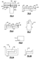
Figure 4 shows an inventivemicro-core circuit 88. The view shown inFigure 4 is through the thickness of themicro-core circuit 88. As shown, there is a variation in the thickness along the dimension illustrated. Thus, there is athicker portion 92 for receiving air from aninlet 91 and anecked down portion 94. AlthoughFigure 4 shows the necked down portion moves inwardly from both sides of theportion 92, the necking could occur on one or the other sides as well. Moreover,Figure 4 depicts aportion 96 that curves downwardly from thenecked portion 94 to follow anupper surface 98 of theinner platform 82. As mentioned, thesame micro-circuit 88 can be embedded inupper platform 83. The cores can be made by ceramic or by RMC. The ceramic cores are made by the ceramic core die and would only require a different shape in the die (they are still pullable). The RMC cores are currently stamped and would just require a different stamping die shape to create the contours or variable thickness. -
Figure 5 shows a potential shape along the width of themicro-core circuit 88. As shown, the shape curves to follow the curvature of atop surface 98 of theinner platform 82 and/or atop surface 98 of theouter platform 83 so thatportions top surface 98, maintaining constant wall thickness. AlthoughFigure 5 shows a core contoured in the width direction, the core may also be contoured in the length direction, as represented by thecurved portion 96 inFigure 4 , which follows acurved portion 101 ontop surface 98. - By the term "follow" and by "same distance," this application simply implies that in general the curvatures may be in the same direction at approximately corresponding locations between the top surface and the
micro-core circuit 88. Thus, the distances from the top surface need not be identically equal, and there may be some variation somewhere along the length. However, in general, in these embodiments, the distance between the top surface and themicro-core circuit 88 will be closer to being equal than if the curvature did not "follow" thetop surface 98. -
Figure 6 shows another embodiment, where the shape of the core does not follow thetop surface 98, resulting inportions 99 being closer to andportions 104 being farther fromtop surface 98. -
Figure 7 shows a blade 110 which incorporates acircuit 112.Circuit 112 may be structured as disclosed above. -
Figure 8 shows anotherpotential component 114 having acircuit 116. Again,circuit 116 may be generally structured as disclosed above.Component 114 could be a blade outer air seal, or a component in a combustor section. -
Figure 9A shows a first method step. A molding operation 110 includes amold 120 receiving molten metal to form acomponent 122.Component 122 may be any of the previously disclosed components. A lostcore 124 is formed and deposited within themold 120. Lost core molding techniques are generally known. As shown, thecore 124 is a micro-core cooling circuit having an average thickness less than or equal to .040 inch (.102 centimeters). Further, thecore 124 has a variation of either the thickness or a contoured surface, away from a generally planar shape to a non-planar shape. -
Figure 9B shows a subsequent step. The material of thecore 124 is leached away leaving a hollow at 126 which provides the micro-core circuit. - It should be understood that micro-core circuits made according to this disclosure can have variations to the contoured shape in any of the three dimensions. By utilizing contoured micro-core circuits, the curvature of the outer surface of the component can be accommodated for. The micro-core circuits can track or follow the contour of an airfoil or platform(s).
- Generally,
component 80 for use in a gas turbine engine comprises a body and amicro-core cooling circuit 86/88 embedded within the body. The micro-core circuit has a variation in either a thickness or contoured surface, away from a generally planar shape to a non-planar shape. - By changing the thickness, cooling air can be directed to those areas which are more in need.
- Although embodiments of this invention have been disclosed, a worker of ordinary skill in this art would recognize that certain modifications would come within the scope of this invention. For that reason, the following claims should be studied to determine the true scope and content of this invention.
Claims (12)
- A component (80; 110; 114) for use in a gas turbine engine comprising:a body and a micro-core cooling circuit (86; 88; 112; 116) embedded within said body, said micro-core circuit (86; 88; 112; 116) having a variation in a thickness (t), and/or a contoured surface, away from a generally planar shape to a non-planar shape.
- The component for use in a gas turbine engine as set forth in claim 1, wherein said micro-core circuit (86; 88; 112; 116) has a thickness, with an average thickness being less than or equal to .040 inch (.102 centimeter).
- The component for use in a gas turbine engine as set forth in claim 1 or 2, wherein said thickness varies.
- The component for use in a gas turbine engine as set forth in any preceding claim, wherein an inlet (91) communicates into said micro-core circuit (88).
- The component for use in a gas turbine engine as set forth in claim 4, wherein said inlet (91) communicates into a thicker portion (92) of said micro-core circuit (88).
- The component for use in a gas turbine engine as set forth in any preceding claim, wherein said micro-core circuit (88) has a length (1) and a width (w) and wherein said contoured surface curves in at least one of said length and said width.
- The component for use in a gas turbine engine as set forth in claim 6, wherein said component (80) has at least one platform (82, 83) and an airfoil (84), said platform (82, 83) and said airfoil (84) curving, and a curve in said micro-core circuit (88) being adjacent to said curve in said airfoil (84).
- The component for use in a gas turbine engine as set forth in claim 6 or 7, wherein said component (80) has an outer surface (98) and said contoured surface of said micro-core circuit (98) follows said outer surface (98).
- The component for use in a gas turbine engine as set forth in claim 6 or 7, wherein said component has an outer surface (98) and said contoured surface of said micro-core circuit (88) has portions closer to said outer surface (98) and other portions spaced further from said outer surface (98).
- The component for use in a gas turbine engine as set forth in any preceding claim, wherein said component (80) is one of a vane, a blade, a blade outer air seal, or a combustor element for use in a gas turbine engine.
- A gas turbine engine (20) comprising:a turbine section (28) and a combustor (26) and at least one of said turbine section (28) and said combustor (26) including a component as set forth in any preceding claim.
- A core for forming a micro-core cooling circuit in a gas turbine engine component comprising:a body having an average thickness less than or equal to .040 inch (.102 centimeter), and said body having a variation in a thickness and/or a contoured surface, away from a generally planar shape to a non-planar shape.
Applications Claiming Priority (1)
| Application Number | Priority Date | Filing Date | Title |
|---|---|---|---|
| US201462069914P | 2014-10-29 | 2014-10-29 |
Publications (2)
| Publication Number | Publication Date |
|---|---|
| EP3015649A1 true EP3015649A1 (en) | 2016-05-04 |
| EP3015649B1 EP3015649B1 (en) | 2018-12-12 |
Family
ID=54360962
Family Applications (1)
| Application Number | Title | Priority Date | Filing Date |
|---|---|---|---|
| EP15191982.6A Active EP3015649B1 (en) | 2014-10-29 | 2015-10-28 | Three dimensional airfoil micro-core cooling chamber |
Country Status (2)
| Country | Link |
|---|---|
| US (1) | US10280761B2 (en) |
| EP (1) | EP3015649B1 (en) |
Families Citing this family (3)
| Publication number | Priority date | Publication date | Assignee | Title |
|---|---|---|---|---|
| US10619492B2 (en) * | 2017-12-11 | 2020-04-14 | United Technologies Corporation | Vane air inlet with fillet |
| US11377964B2 (en) | 2018-11-09 | 2022-07-05 | Raytheon Technologies Corporation | Airfoil with cooling passage network having arced leading edge |
| US10767492B2 (en) | 2018-12-18 | 2020-09-08 | General Electric Company | Turbine engine airfoil |
Citations (3)
| Publication number | Priority date | Publication date | Assignee | Title |
|---|---|---|---|---|
| EP1101899A1 (en) * | 1999-11-18 | 2001-05-23 | United Technologies Corporation | Method and apparatus for cooling an airfoil |
| EP1445424A2 (en) * | 2003-02-05 | 2004-08-11 | United Technologies Corporation | Microcircuit cooling for a turbine blade tip |
| EP1884621A2 (en) * | 2006-07-28 | 2008-02-06 | United Technologies Corporation | Serpentine microciruit cooling with pressure side features |
Family Cites Families (19)
| Publication number | Priority date | Publication date | Assignee | Title |
|---|---|---|---|---|
| US7137776B2 (en) * | 2002-06-19 | 2006-11-21 | United Technologies Corporation | Film cooling for microcircuits |
| US6994521B2 (en) * | 2003-03-12 | 2006-02-07 | Florida Turbine Technologies, Inc. | Leading edge diffusion cooling of a turbine airfoil for a gas turbine engine |
| US6955522B2 (en) * | 2003-04-07 | 2005-10-18 | United Technologies Corporation | Method and apparatus for cooling an airfoil |
| US7255536B2 (en) * | 2005-05-23 | 2007-08-14 | United Technologies Corporation | Turbine airfoil platform cooling circuit |
| US7621719B2 (en) * | 2005-09-30 | 2009-11-24 | United Technologies Corporation | Multiple cooling schemes for turbine blade outer air seal |
| US7311498B2 (en) * | 2005-11-23 | 2007-12-25 | United Technologies Corporation | Microcircuit cooling for blades |
| US7513744B2 (en) * | 2006-07-18 | 2009-04-07 | United Technologies Corporation | Microcircuit cooling and tip blowing |
| US7527474B1 (en) * | 2006-08-11 | 2009-05-05 | Florida Turbine Technologies, Inc. | Turbine airfoil with mini-serpentine cooling passages |
| US7537431B1 (en) * | 2006-08-21 | 2009-05-26 | Florida Turbine Technologies, Inc. | Turbine blade tip with mini-serpentine cooling circuit |
| US8511992B2 (en) * | 2008-01-22 | 2013-08-20 | United Technologies Corporation | Minimization of fouling and fluid losses in turbine airfoils |
| US8572844B2 (en) * | 2008-08-29 | 2013-11-05 | United Technologies Corporation | Airfoil with leading edge cooling passage |
| US8303252B2 (en) * | 2008-10-16 | 2012-11-06 | United Technologies Corporation | Airfoil with cooling passage providing variable heat transfer rate |
| US8109725B2 (en) * | 2008-12-15 | 2012-02-07 | United Technologies Corporation | Airfoil with wrapped leading edge cooling passage |
| US8066485B1 (en) * | 2009-05-15 | 2011-11-29 | Florida Turbine Technologies, Inc. | Turbine blade with tip section cooling |
| US8449246B1 (en) * | 2010-12-01 | 2013-05-28 | Florida Turbine Technologies, Inc. | BOAS with micro serpentine cooling |
| US8858159B2 (en) * | 2011-10-28 | 2014-10-14 | United Technologies Corporation | Gas turbine engine component having wavy cooling channels with pedestals |
| FR2990367B1 (en) * | 2012-05-11 | 2014-05-16 | Snecma | TOOLING FOR MANUFACTURING A FOUNDRY CORE FOR A TURBOMACHINE BLADE |
| FR3022810B1 (en) * | 2014-06-30 | 2019-09-20 | Safran Aircraft Engines | PROCESS FOR PRODUCING A CORE FOR MOLDING A DAWN |
| US10030523B2 (en) * | 2015-02-13 | 2018-07-24 | United Technologies Corporation | Article having cooling passage with undulating profile |
-
2015
- 2015-10-01 US US14/872,272 patent/US10280761B2/en active Active
- 2015-10-28 EP EP15191982.6A patent/EP3015649B1/en active Active
Patent Citations (3)
| Publication number | Priority date | Publication date | Assignee | Title |
|---|---|---|---|---|
| EP1101899A1 (en) * | 1999-11-18 | 2001-05-23 | United Technologies Corporation | Method and apparatus for cooling an airfoil |
| EP1445424A2 (en) * | 2003-02-05 | 2004-08-11 | United Technologies Corporation | Microcircuit cooling for a turbine blade tip |
| EP1884621A2 (en) * | 2006-07-28 | 2008-02-06 | United Technologies Corporation | Serpentine microciruit cooling with pressure side features |
Also Published As
| Publication number | Publication date |
|---|---|
| US20160194964A1 (en) | 2016-07-07 |
| EP3015649B1 (en) | 2018-12-12 |
| US10280761B2 (en) | 2019-05-07 |
Similar Documents
| Publication | Publication Date | Title |
|---|---|---|
| US11148191B2 (en) | Core arrangement for turbine engine component | |
| EP3056674B1 (en) | Article having cooling passage with undulating profile | |
| EP2942488B1 (en) | Blade for a gas turbine engine, gas turbine engine and method of cooling a blade for a gas turbine engine | |
| US10677069B2 (en) | Component core with shaped edges | |
| EP3034791B1 (en) | Heat transfer pedestals with flow guide features | |
| EP3342982B1 (en) | Inclined crossover passages for internal airfoil cavities | |
| EP2985417A1 (en) | Gas turbine engine component and wall | |
| EP3477056B1 (en) | Gas turbine engine airfoil array | |
| US10151210B2 (en) | Endwall contouring for airfoil rows with varying airfoil geometries | |
| EP3078807A1 (en) | Cooling passages for a gas turbine engine component | |
| EP3015649B1 (en) | Three dimensional airfoil micro-core cooling chamber | |
| EP3112596A1 (en) | Gas turbine engine airfoil with bi-axial skin cooling passage and corresponding gas turbine engine | |
| EP3086893B1 (en) | Lost core structural frame | |
| EP2971544B1 (en) | Gas turbine engine component cooling with interleaved facing trip strips | |
| EP3045666B1 (en) | Airfoil platform with cooling feed orifices | |
| EP3064291A1 (en) | Rib bumper system | |
| EP3060761B1 (en) | Turbine airfoil cooling core exit | |
| EP3406851A1 (en) | Component for a gas turbine engine and method of forming a core assembly | |
| EP2975222A1 (en) | Cooled pocket in a turbine vane platform |
Legal Events
| Date | Code | Title | Description |
|---|---|---|---|
| PUAI | Public reference made under article 153(3) epc to a published international application that has entered the european phase |
Free format text: ORIGINAL CODE: 0009012 |
|
| AK | Designated contracting states |
Kind code of ref document: A1 Designated state(s): AL AT BE BG CH CY CZ DE DK EE ES FI FR GB GR HR HU IE IS IT LI LT LU LV MC MK MT NL NO PL PT RO RS SE SI SK SM TR |
|
| AX | Request for extension of the european patent |
Extension state: BA ME |
|
| RAP1 | Party data changed (applicant data changed or rights of an application transferred) |
Owner name: UNITED TECHNOLOGIES CORPORATION |
|
| STAA | Information on the status of an ep patent application or granted ep patent |
Free format text: STATUS: REQUEST FOR EXAMINATION WAS MADE |
|
| 17P | Request for examination filed |
Effective date: 20161104 |
|
| RBV | Designated contracting states (corrected) |
Designated state(s): AL AT BE BG CH CY CZ DE DK EE ES FI FR GB GR HR HU IE IS IT LI LT LU LV MC MK MT NL NO PL PT RO RS SE SI SK SM TR |
|
| STAA | Information on the status of an ep patent application or granted ep patent |
Free format text: STATUS: EXAMINATION IS IN PROGRESS |
|
| 17Q | First examination report despatched |
Effective date: 20170721 |
|
| GRAP | Despatch of communication of intention to grant a patent |
Free format text: ORIGINAL CODE: EPIDOSNIGR1 |
|
| STAA | Information on the status of an ep patent application or granted ep patent |
Free format text: STATUS: GRANT OF PATENT IS INTENDED |
|
| INTG | Intention to grant announced |
Effective date: 20180620 |
|
| GRAS | Grant fee paid |
Free format text: ORIGINAL CODE: EPIDOSNIGR3 |
|
| GRAA | (expected) grant |
Free format text: ORIGINAL CODE: 0009210 |
|
| STAA | Information on the status of an ep patent application or granted ep patent |
Free format text: STATUS: THE PATENT HAS BEEN GRANTED |
|
| AK | Designated contracting states |
Kind code of ref document: B1 Designated state(s): AL AT BE BG CH CY CZ DE DK EE ES FI FR GB GR HR HU IE IS IT LI LT LU LV MC MK MT NL NO PL PT RO RS SE SI SK SM TR |
|
| REG | Reference to a national code |
Ref country code: GB Ref legal event code: FG4D |
|
| REG | Reference to a national code |
Ref country code: CH Ref legal event code: EP |
|
| REG | Reference to a national code |
Ref country code: AT Ref legal event code: REF Ref document number: 1076247 Country of ref document: AT Kind code of ref document: T Effective date: 20181215 |
|
| REG | Reference to a national code |
Ref country code: DE Ref legal event code: R096 Ref document number: 602015021173 Country of ref document: DE |
|
| REG | Reference to a national code |
Ref country code: IE Ref legal event code: FG4D |
|
| REG | Reference to a national code |
Ref country code: NL Ref legal event code: MP Effective date: 20181212 |
|
| REG | Reference to a national code |
Ref country code: LT Ref legal event code: MG4D |
|
| PG25 | Lapsed in a contracting state [announced via postgrant information from national office to epo] |
Ref country code: ES Free format text: LAPSE BECAUSE OF FAILURE TO SUBMIT A TRANSLATION OF THE DESCRIPTION OR TO PAY THE FEE WITHIN THE PRESCRIBED TIME-LIMIT Effective date: 20181212 Ref country code: NO Free format text: LAPSE BECAUSE OF FAILURE TO SUBMIT A TRANSLATION OF THE DESCRIPTION OR TO PAY THE FEE WITHIN THE PRESCRIBED TIME-LIMIT Effective date: 20190312 Ref country code: LT Free format text: LAPSE BECAUSE OF FAILURE TO SUBMIT A TRANSLATION OF THE DESCRIPTION OR TO PAY THE FEE WITHIN THE PRESCRIBED TIME-LIMIT Effective date: 20181212 Ref country code: BG Free format text: LAPSE BECAUSE OF FAILURE TO SUBMIT A TRANSLATION OF THE DESCRIPTION OR TO PAY THE FEE WITHIN THE PRESCRIBED TIME-LIMIT Effective date: 20190312 Ref country code: HR Free format text: LAPSE BECAUSE OF FAILURE TO SUBMIT A TRANSLATION OF THE DESCRIPTION OR TO PAY THE FEE WITHIN THE PRESCRIBED TIME-LIMIT Effective date: 20181212 Ref country code: LV Free format text: LAPSE BECAUSE OF FAILURE TO SUBMIT A TRANSLATION OF THE DESCRIPTION OR TO PAY THE FEE WITHIN THE PRESCRIBED TIME-LIMIT Effective date: 20181212 Ref country code: FI Free format text: LAPSE BECAUSE OF FAILURE TO SUBMIT A TRANSLATION OF THE DESCRIPTION OR TO PAY THE FEE WITHIN THE PRESCRIBED TIME-LIMIT Effective date: 20181212 |
|
| REG | Reference to a national code |
Ref country code: AT Ref legal event code: MK05 Ref document number: 1076247 Country of ref document: AT Kind code of ref document: T Effective date: 20181212 |
|
| PG25 | Lapsed in a contracting state [announced via postgrant information from national office to epo] |
Ref country code: RS Free format text: LAPSE BECAUSE OF FAILURE TO SUBMIT A TRANSLATION OF THE DESCRIPTION OR TO PAY THE FEE WITHIN THE PRESCRIBED TIME-LIMIT Effective date: 20181212 Ref country code: AL Free format text: LAPSE BECAUSE OF FAILURE TO SUBMIT A TRANSLATION OF THE DESCRIPTION OR TO PAY THE FEE WITHIN THE PRESCRIBED TIME-LIMIT Effective date: 20181212 Ref country code: SE Free format text: LAPSE BECAUSE OF FAILURE TO SUBMIT A TRANSLATION OF THE DESCRIPTION OR TO PAY THE FEE WITHIN THE PRESCRIBED TIME-LIMIT Effective date: 20181212 Ref country code: GR Free format text: LAPSE BECAUSE OF FAILURE TO SUBMIT A TRANSLATION OF THE DESCRIPTION OR TO PAY THE FEE WITHIN THE PRESCRIBED TIME-LIMIT Effective date: 20190313 |
|
| PG25 | Lapsed in a contracting state [announced via postgrant information from national office to epo] |
Ref country code: NL Free format text: LAPSE BECAUSE OF FAILURE TO SUBMIT A TRANSLATION OF THE DESCRIPTION OR TO PAY THE FEE WITHIN THE PRESCRIBED TIME-LIMIT Effective date: 20181212 |
|
| PG25 | Lapsed in a contracting state [announced via postgrant information from national office to epo] |
Ref country code: PT Free format text: LAPSE BECAUSE OF FAILURE TO SUBMIT A TRANSLATION OF THE DESCRIPTION OR TO PAY THE FEE WITHIN THE PRESCRIBED TIME-LIMIT Effective date: 20190412 Ref country code: IT Free format text: LAPSE BECAUSE OF FAILURE TO SUBMIT A TRANSLATION OF THE DESCRIPTION OR TO PAY THE FEE WITHIN THE PRESCRIBED TIME-LIMIT Effective date: 20181212 Ref country code: PL Free format text: LAPSE BECAUSE OF FAILURE TO SUBMIT A TRANSLATION OF THE DESCRIPTION OR TO PAY THE FEE WITHIN THE PRESCRIBED TIME-LIMIT Effective date: 20181212 Ref country code: CZ Free format text: LAPSE BECAUSE OF FAILURE TO SUBMIT A TRANSLATION OF THE DESCRIPTION OR TO PAY THE FEE WITHIN THE PRESCRIBED TIME-LIMIT Effective date: 20181212 |
|
| PG25 | Lapsed in a contracting state [announced via postgrant information from national office to epo] |
Ref country code: SM Free format text: LAPSE BECAUSE OF FAILURE TO SUBMIT A TRANSLATION OF THE DESCRIPTION OR TO PAY THE FEE WITHIN THE PRESCRIBED TIME-LIMIT Effective date: 20181212 Ref country code: IS Free format text: LAPSE BECAUSE OF FAILURE TO SUBMIT A TRANSLATION OF THE DESCRIPTION OR TO PAY THE FEE WITHIN THE PRESCRIBED TIME-LIMIT Effective date: 20190412 Ref country code: SK Free format text: LAPSE BECAUSE OF FAILURE TO SUBMIT A TRANSLATION OF THE DESCRIPTION OR TO PAY THE FEE WITHIN THE PRESCRIBED TIME-LIMIT Effective date: 20181212 Ref country code: EE Free format text: LAPSE BECAUSE OF FAILURE TO SUBMIT A TRANSLATION OF THE DESCRIPTION OR TO PAY THE FEE WITHIN THE PRESCRIBED TIME-LIMIT Effective date: 20181212 Ref country code: RO Free format text: LAPSE BECAUSE OF FAILURE TO SUBMIT A TRANSLATION OF THE DESCRIPTION OR TO PAY THE FEE WITHIN THE PRESCRIBED TIME-LIMIT Effective date: 20181212 |
|
| REG | Reference to a national code |
Ref country code: DE Ref legal event code: R097 Ref document number: 602015021173 Country of ref document: DE |
|
| PLBE | No opposition filed within time limit |
Free format text: ORIGINAL CODE: 0009261 |
|
| STAA | Information on the status of an ep patent application or granted ep patent |
Free format text: STATUS: NO OPPOSITION FILED WITHIN TIME LIMIT |
|
| PG25 | Lapsed in a contracting state [announced via postgrant information from national office to epo] |
Ref country code: DK Free format text: LAPSE BECAUSE OF FAILURE TO SUBMIT A TRANSLATION OF THE DESCRIPTION OR TO PAY THE FEE WITHIN THE PRESCRIBED TIME-LIMIT Effective date: 20181212 Ref country code: AT Free format text: LAPSE BECAUSE OF FAILURE TO SUBMIT A TRANSLATION OF THE DESCRIPTION OR TO PAY THE FEE WITHIN THE PRESCRIBED TIME-LIMIT Effective date: 20181212 Ref country code: SI Free format text: LAPSE BECAUSE OF FAILURE TO SUBMIT A TRANSLATION OF THE DESCRIPTION OR TO PAY THE FEE WITHIN THE PRESCRIBED TIME-LIMIT Effective date: 20181212 |
|
| 26N | No opposition filed |
Effective date: 20190913 |
|
| PG25 | Lapsed in a contracting state [announced via postgrant information from national office to epo] |
Ref country code: TR Free format text: LAPSE BECAUSE OF FAILURE TO SUBMIT A TRANSLATION OF THE DESCRIPTION OR TO PAY THE FEE WITHIN THE PRESCRIBED TIME-LIMIT Effective date: 20181212 |
|
| PG25 | Lapsed in a contracting state [announced via postgrant information from national office to epo] |
Ref country code: MC Free format text: LAPSE BECAUSE OF FAILURE TO SUBMIT A TRANSLATION OF THE DESCRIPTION OR TO PAY THE FEE WITHIN THE PRESCRIBED TIME-LIMIT Effective date: 20181212 |
|
| REG | Reference to a national code |
Ref country code: CH Ref legal event code: PL |
|
| PG25 | Lapsed in a contracting state [announced via postgrant information from national office to epo] |
Ref country code: CH Free format text: LAPSE BECAUSE OF NON-PAYMENT OF DUE FEES Effective date: 20191031 Ref country code: LU Free format text: LAPSE BECAUSE OF NON-PAYMENT OF DUE FEES Effective date: 20191028 Ref country code: LI Free format text: LAPSE BECAUSE OF NON-PAYMENT OF DUE FEES Effective date: 20191031 |
|
| REG | Reference to a national code |
Ref country code: BE Ref legal event code: MM Effective date: 20191031 |
|
| PG25 | Lapsed in a contracting state [announced via postgrant information from national office to epo] |
Ref country code: BE Free format text: LAPSE BECAUSE OF NON-PAYMENT OF DUE FEES Effective date: 20191031 |
|
| PG25 | Lapsed in a contracting state [announced via postgrant information from national office to epo] |
Ref country code: IE Free format text: LAPSE BECAUSE OF NON-PAYMENT OF DUE FEES Effective date: 20191028 |
|
| PG25 | Lapsed in a contracting state [announced via postgrant information from national office to epo] |
Ref country code: CY Free format text: LAPSE BECAUSE OF FAILURE TO SUBMIT A TRANSLATION OF THE DESCRIPTION OR TO PAY THE FEE WITHIN THE PRESCRIBED TIME-LIMIT Effective date: 20181212 |
|
| PG25 | Lapsed in a contracting state [announced via postgrant information from national office to epo] |
Ref country code: MT Free format text: LAPSE BECAUSE OF FAILURE TO SUBMIT A TRANSLATION OF THE DESCRIPTION OR TO PAY THE FEE WITHIN THE PRESCRIBED TIME-LIMIT Effective date: 20181212 Ref country code: HU Free format text: LAPSE BECAUSE OF FAILURE TO SUBMIT A TRANSLATION OF THE DESCRIPTION OR TO PAY THE FEE WITHIN THE PRESCRIBED TIME-LIMIT; INVALID AB INITIO Effective date: 20151028 |
|
| PG25 | Lapsed in a contracting state [announced via postgrant information from national office to epo] |
Ref country code: MK Free format text: LAPSE BECAUSE OF FAILURE TO SUBMIT A TRANSLATION OF THE DESCRIPTION OR TO PAY THE FEE WITHIN THE PRESCRIBED TIME-LIMIT Effective date: 20181212 |
|
| REG | Reference to a national code |
Ref country code: DE Ref legal event code: R081 Ref document number: 602015021173 Country of ref document: DE Owner name: RAYTHEON TECHNOLOGIES CORPORATION (N.D.GES.D.S, US Free format text: FORMER OWNER: UNITED TECHNOLOGIES CORPORATION, FARMINGTON, CONN., US Ref country code: DE Ref legal event code: R081 Ref document number: 602015021173 Country of ref document: DE Owner name: RTX CORPORATION (N.D.GES.D. STAATES DELAWARE),, US Free format text: FORMER OWNER: UNITED TECHNOLOGIES CORPORATION, FARMINGTON, CONN., US |
|
| P01 | Opt-out of the competence of the unified patent court (upc) registered |
Effective date: 20230520 |
|
| PGFP | Annual fee paid to national office [announced via postgrant information from national office to epo] |
Ref country code: GB Payment date: 20250923 Year of fee payment: 11 |
|
| PGFP | Annual fee paid to national office [announced via postgrant information from national office to epo] |
Ref country code: FR Payment date: 20250924 Year of fee payment: 11 |
|
| REG | Reference to a national code |
Ref country code: DE Ref legal event code: R081 Ref document number: 602015021173 Country of ref document: DE Owner name: RTX CORPORATION (N.D.GES.D. STAATES DELAWARE),, US Free format text: FORMER OWNER: RAYTHEON TECHNOLOGIES CORPORATION (N.D.GES.D.STAATES DELAWARE), ARLINGTON, VA, US |
|
| PGFP | Annual fee paid to national office [announced via postgrant information from national office to epo] |
Ref country code: DE Payment date: 20250923 Year of fee payment: 11 |