EP3015616A1 - Mounting unit - Google Patents
Mounting unit Download PDFInfo
- Publication number
- EP3015616A1 EP3015616A1 EP15191085.8A EP15191085A EP3015616A1 EP 3015616 A1 EP3015616 A1 EP 3015616A1 EP 15191085 A EP15191085 A EP 15191085A EP 3015616 A1 EP3015616 A1 EP 3015616A1
- Authority
- EP
- European Patent Office
- Prior art keywords
- mounting unit
- mid
- unit according
- flange
- opening
- Prior art date
- Legal status (The legal status is an assumption and is not a legal conclusion. Google has not performed a legal analysis and makes no representation as to the accuracy of the status listed.)
- Granted
Links
Images



Classifications
-
- E—FIXED CONSTRUCTIONS
- E04—BUILDING
- E04D—ROOF COVERINGS; SKY-LIGHTS; GUTTERS; ROOF-WORKING TOOLS
- E04D13/00—Special arrangements or devices in connection with roof coverings; Protection against birds; Roof drainage ; Sky-lights
- E04D13/14—Junctions of roof sheathings to chimneys or other parts extending above the roof
- E04D13/1407—Junctions of roof sheathings to chimneys or other parts extending above the roof for flat roofs
-
- E—FIXED CONSTRUCTIONS
- E04—BUILDING
- E04D—ROOF COVERINGS; SKY-LIGHTS; GUTTERS; ROOF-WORKING TOOLS
- E04D13/00—Special arrangements or devices in connection with roof coverings; Protection against birds; Roof drainage ; Sky-lights
- E04D13/03—Sky-lights; Domes; Ventilating sky-lights
- E04D13/0305—Supports or connecting means for sky-lights of flat or domed shape
-
- E—FIXED CONSTRUCTIONS
- E04—BUILDING
- E04D—ROOF COVERINGS; SKY-LIGHTS; GUTTERS; ROOF-WORKING TOOLS
- E04D13/00—Special arrangements or devices in connection with roof coverings; Protection against birds; Roof drainage ; Sky-lights
- E04D13/03—Sky-lights; Domes; Ventilating sky-lights
- E04D2013/034—Daylight conveying tubular skylights
Definitions
- This invention concerns a mounting unit, and particularly a mounting unit for mounting a building component on a flat surface such as a roof, and particularly a membrane roof.
- Membrane roofing is being increasingly used on flat or nearly flat roofs, in commercial applications, and also increasingly in residential applications. It is often required to mount building components on such roofs such as for instance a light tube to permit natural light to enter these buildings. Mounting such components extending through a membrane roof can involve a not insignificant amount of work, and it is important to ensure that such mounting is carried out properly such that no water leakage can occur.
- a mounting unit for mounting a building component on a flat surface, the unit comprising an upper member with an upstanding part defining an opening to receive a building component and a flange surrounding the upstanding part, a lower member with an opening corresponding to the opening in the upstanding part and a flange surrounding the opening, and a mid member in the form of a piece of a membrane material with an opening therein corresponding to the openings in the upper and lower members, the upper member being located on the lower member with the mid member extending between the flanges of the upper and lower members, and extending outwardly beyond the flanges of the upper and lower member, the mid member being bonded to the flanges of the upper and lower members.
- the lower member may include an upstanding part defining the opening therein, and the upper member may be a sliding fit on the lower member.
- the mid member may be bonded to the lower member by a contact adhesive.
- the mid member may be bonded to the upper member by an adhesive tape, and a primer may be applied to the mid member and/or upper member prior to application of the adhesive tape.
- the opening in the mid member may be such that the edge of the mid member around the opening lies adjacent the upstanding part of the lower member.
- the flange on the lower member may extend for a greater extent than the flange on the upper member, such that the lower member flange extends beyond the flange on the upper member.
- An outer area of the lower member flange may not be bonded to the mid member, so as to permit mechanical attachment of the lower member to the flat surface, and the outer area may extend around the whole perimeter of the lower member. The outer area may be provided beyond the perimeter of the upper member.
- the mid member may be made of synthetic rubber and may be made of EPDM (ethylene propylene diene monomer). Alternatively the mid member may be made of PVC.
- the lower member and/or upper member may be made of plastics material or metal.
- FIG. 1 shows a mounting unit 10 mounting a building component such as a light tube assembly 12, which assembly 12 includes a dome 14 and a mounting cap 16.
- the unit 10 comprises an upper member 18, lower member 20 and mid member 22.
- the upper member 18 comprises a square flange 24 with an upstanding part 26 defining a central opening 28 to receive the light tube assembly 12.
- the upstanding part 26 has an side wall 30 which tapers upwardly, and four hollow locating outwardly extending projections 32 spaced around the side walls 30 and extending vertically.
- the lower member 20 has a generally similar form to the upper member 18, with a square flange 34, but which extends for a greater extent than the upper member flange 24. Again an upstanding part 36 is provided with a side wall 38, a central opening 40, and four locating projections 42.
- the upper and lower members 18, 20 are such that the upper member can slidingly fit together with the lower member locating projections 42 locating within the upper member locating projections 32.
- the mid member 22 comprises a square sheet of synthetic rubber, which in this instance is EPDM.
- a central circular opening 44 is provided which corresponds to the openings 28, 40.
- the mounting unit 10 may be formed by the following method.
- the mid member 22 is located in position on the lower member 20 and then folded over on itself in half such that half of it covers the lower member flange 34.
- Contact adhesive is applied to the lower member flange 34 and respective part of the mid member 22, leaving an outer area 46 around the perimeter of the lower member flange 34 with no adhesive applied to.
- the parts of the lower member 20 and mid member 22 which have adhesive applied thereto can be pressed together, and adhesive applied to the other halves of the lower and mid members 20, 22 which previously did not have adhesive applied thereto, again leaving the outer area 46 around the edge of the lower member 20 with no adhesive thereof. This can be seen in Fig. 5 and in this instance extends for at least 75mm from the edge of the lower member flange 34.
- the upper member 18 can be located in position on the lower member 20, with the lower member locating projections 42 locating within the upper member locating projections 32.
- the location of the upper member 18 on the mid member 22 can be marked and the upper member 18 removed.
- a priming material such as Firestone Quick Prime Plus® can be applied around an outer part of the underside of the upper member flange 24, and the corresponding location on the mid member 22.
- An appropriate adhesive tape for use on membrane roofs can then be applied to the part of the upper member flange 24 provided with primer.
- the backing paper from the tape can be removed and the upper member 18 can be located on the lower member 20 and pushed into position on the mid member 22, adhering thereto.
- the mid member 22 can be peeled back to provide access to the outer 46 of the lower member flange 34 which is not adhered to the mid member 22, thereby permitting ready mechanical mounting of the lower member 20 to a roof or elsewhere.
- a building component such as the light tube assembly 12 can be mounted on the unit 10 by any conventional manner.
- the upper and lower members 18, 20 are made of an appropriate weather resistant plastics material. As an alternative they could be formed of pressed metal.
- the mid member may be made of a different material, and could be made for instance of PVC.
- the above example has four locating projections, a different number or configuration of projections could be provided, and for instance with larger size units a greater number of projections could be provided.
- Units according to the invention could mount other assemblies such as for example roof lights.
- An insulating layer or component could be included in the unit, for instance on the underside of the lower member.
- the upper and lower members may be differently formed, and may mount different building components.
- the different parts of the unit could be bonded together by different materials or a different method.
Landscapes
- Engineering & Computer Science (AREA)
- Architecture (AREA)
- Civil Engineering (AREA)
- Structural Engineering (AREA)
- Roof Covering Using Slabs Or Stiff Sheets (AREA)
- Tents Or Canopies (AREA)
Abstract
Description
- This invention concerns a mounting unit, and particularly a mounting unit for mounting a building component on a flat surface such as a roof, and particularly a membrane roof.
- Membrane roofing is being increasingly used on flat or nearly flat roofs, in commercial applications, and also increasingly in residential applications. It is often required to mount building components on such roofs such as for instance a light tube to permit natural light to enter these buildings. Mounting such components extending through a membrane roof can involve a not insignificant amount of work, and it is important to ensure that such mounting is carried out properly such that no water leakage can occur.
- According to the present invention there is provided a mounting unit for mounting a building component on a flat surface, the unit comprising an upper member with an upstanding part defining an opening to receive a building component and a flange surrounding the upstanding part, a lower member with an opening corresponding to the opening in the upstanding part and a flange surrounding the opening, and a mid member in the form of a piece of a membrane material with an opening therein corresponding to the openings in the upper and lower members, the upper member being located on the lower member with the mid member extending between the flanges of the upper and lower members, and extending outwardly beyond the flanges of the upper and lower member, the mid member being bonded to the flanges of the upper and lower members.
- The lower member may include an upstanding part defining the opening therein, and the upper member may be a sliding fit on the lower member.
- The mid member may be bonded to the lower member by a contact adhesive.
- The mid member may be bonded to the upper member by an adhesive tape, and a primer may be applied to the mid member and/or upper member prior to application of the adhesive tape.
- The opening in the mid member may be such that the edge of the mid member around the opening lies adjacent the upstanding part of the lower member.
- The flange on the lower member may extend for a greater extent than the flange on the upper member, such that the lower member flange extends beyond the flange on the upper member.
- An outer area of the lower member flange may not be bonded to the mid member, so as to permit mechanical attachment of the lower member to the flat surface, and the outer area may extend around the whole perimeter of the lower member. The outer area may be provided beyond the perimeter of the upper member.
- The mid member may be made of synthetic rubber and may be made of EPDM (ethylene propylene diene monomer). Alternatively the mid member may be made of PVC.
- The lower member and/or upper member may be made of plastics material or metal.
- An embodiment of the present invention will now be described by way of example only and with reference to the accompanying drawings, in which:-
-
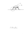
Fig. 1 is a diagrammatic side view of a mounting unit according to the invention mounting a building component; -
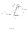
Fig. 2 is a cross sectional view along the line A-A ofFig. 1 ; -
Fig. 3 is a detailed view of the circled part inFig. 2 ; -
Fig. 4 is a diagrammatic perspective view of the mounting unit ofFig. 1 ; and -
Fig. 5 is a similar view toFig. 4 but diagrammatically illustrating further features. - The drawings show a
mounting unit 10 mounting a building component such as alight tube assembly 12, whichassembly 12 includes adome 14 and amounting cap 16. - The
unit 10 comprises anupper member 18,lower member 20 andmid member 22. Theupper member 18 comprises asquare flange 24 with anupstanding part 26 defining acentral opening 28 to receive thelight tube assembly 12. Theupstanding part 26 has anside wall 30 which tapers upwardly, and four hollow locating outwardly extendingprojections 32 spaced around theside walls 30 and extending vertically. - The
lower member 20 has a generally similar form to theupper member 18, with asquare flange 34, but which extends for a greater extent than theupper member flange 24. Again anupstanding part 36 is provided with aside wall 38, acentral opening 40, and four locatingprojections 42. The upper andlower members member locating projections 42 locating within the uppermember locating projections 32. - The
mid member 22 comprises a square sheet of synthetic rubber, which in this instance is EPDM. A centralcircular opening 44 is provided which corresponds to theopenings - The
mounting unit 10 may be formed by the following method. Themid member 22 is located in position on thelower member 20 and then folded over on itself in half such that half of it covers thelower member flange 34. Contact adhesive is applied to thelower member flange 34 and respective part of themid member 22, leaving anouter area 46 around the perimeter of thelower member flange 34 with no adhesive applied to. The parts of thelower member 20 andmid member 22 which have adhesive applied thereto can be pressed together, and adhesive applied to the other halves of the lower andmid members outer area 46 around the edge of thelower member 20 with no adhesive thereof. This can be seen inFig. 5 and in this instance extends for at least 75mm from the edge of thelower member flange 34. - The
upper member 18 can be located in position on thelower member 20, with the lowermember locating projections 42 locating within the uppermember locating projections 32. The location of theupper member 18 on themid member 22 can be marked and theupper member 18 removed. A priming material such as Firestone Quick Prime Plus® can be applied around an outer part of the underside of theupper member flange 24, and the corresponding location on themid member 22. An appropriate adhesive tape for use on membrane roofs can then be applied to the part of theupper member flange 24 provided with primer. The backing paper from the tape can be removed and theupper member 18 can be located on thelower member 20 and pushed into position on themid member 22, adhering thereto. - This therefore provides a
unit 10 which can readily be mounted in an appropriate space in a membrane roof area. Themid member 22 can be peeled back to provide access to the outer 46 of thelower member flange 34 which is not adhered to themid member 22, thereby permitting ready mechanical mounting of thelower member 20 to a roof or elsewhere. A building component such as thelight tube assembly 12 can be mounted on theunit 10 by any conventional manner. - The upper and
lower members - There is thus described a mounting unit which readily permits building components to be mounted on a membrane roof, whilst providing a good seal around the mounting unit. This can avoid significant additional work being carried out on site which otherwise would be required in mounting such building components directly onto a membrane roof or similar.
- It is to be realised that various modifications may be made without departing from the scope of the invention. For instance the mid member may be made of a different material, and could be made for instance of PVC. Whilst the above example has four locating projections, a different number or configuration of projections could be provided, and for instance with larger size units a greater number of projections could be provided.
- The above described example mounts a light tube assembly. Units according to the invention could mount other assemblies such as for example roof lights. An insulating layer or component could be included in the unit, for instance on the underside of the lower member. The upper and lower members may be differently formed, and may mount different building components. The different parts of the unit could be bonded together by different materials or a different method.
- Whilst endeavouring in the foregoing specification to draw attention to those features of the invention believed to be of particular importance it should be understood that the Applicant claims protection in respect of any patentable feature or combination of features hereinbefore referred to and/or shown in the drawings whether or not particular emphasis has been placed thereon.
Claims (15)
- A mounting unit (10) for mounting a building component (12) on a flat surface, the unit (10) comprising an upper member (18) with an upstanding part (26) defining an opening (28) to receive a building component (12) and a flange (24) surrounding the upstanding part (26), a lower member (20) with an opening (40) corresponding to the opening (28) in the upper member upstanding part (26) and a flange (34) surrounding the opening (40), and a mid member (22) in the form of a piece of a membrane material with an opening (44) therein corresponding to the openings (28, 40) in the upper and lower members (18, 20), the upper member (18) being located on the lower member (20) with the mid member (22) extending between the flanges (24, 34) of the upper and lower members (18, 20), and extending outwardly beyond the flanges (24, 34) of the upper and lower members (18, 20), the mid member (22) being bonded to the flanges (24, 34) of the upper and lower members (18, 20).
- A mounting unit according to claim 1, characterised in that the lower member (20) includes an upstanding part (36) defining the opening (40) therein.
- A mounting unit according to claim 2, characterised in that the upper member (20) is a sliding fit on the lower member (18).
- A mounting unit according to any of the preceding claims, characterised in that the mid member (22) is bonded to the lower member (18) by a contact adhesive.
- A mounting unit according to any of claims 1 to 3, characterised in that the mid member (22) is bonded to the upper member (20) by an adhesive tape.
- A mounting unit according to claim 5, characterised in that a primer is applied to the mid member (22) and/or upper member (20) prior to application of the adhesive tape.
- A mounting unit according to any of the preceding claims, characterised in that the opening (44) in the mid member is such that the edge of the mid member (22) around the opening lies adjacent the upstanding part (36) of the lower member (20).
- A mounting unit according to any of the preceding claims, characterised in that the flange (34) on the lower member (20) extends for a greater extent than the flange (24) on the upper member (18), such that the lower member flange (34) extends beyond the flange (24) on the upper member.
- A mounting unit according to any of the preceding claims, characterised in that an outer area of the lower member flange (34) is not bonded to the mid member (22), so as to permit mechanical attachment of the lower member (20) to the flat surface.
- A mounting unit according to claim 9, characterised in that the outer area extends around the whole perimeter of the lower member (20).
- A mounting unit according to claim 10, characterised in that the outer area is provided beyond the perimeter of the upper member (18).
- A mounting unit according to any of the preceding claims, characterised in that the mid member (22) is made of synthetic rubber.
- A mounting unit according to claim 12, characterised in that the mid member (22) is EPDM (ethylene propylene diene monomer).
- A mounting unit according to any of claims 1 to 11, characterised in that the mid member (22) is PVC.
- A mounting unit according to any of the preceding claims, characterised in that the lower member (20) and/or upper member (18) are made of plastics material or metal.
Applications Claiming Priority (1)
| Application Number | Priority Date | Filing Date | Title |
|---|---|---|---|
| GBGB1419231.4A GB201419231D0 (en) | 2014-10-29 | 2014-10-29 | Mounting unit |
Publications (2)
| Publication Number | Publication Date |
|---|---|
| EP3015616A1 true EP3015616A1 (en) | 2016-05-04 |
| EP3015616B1 EP3015616B1 (en) | 2017-07-12 |
Family
ID=52103569
Family Applications (1)
| Application Number | Title | Priority Date | Filing Date |
|---|---|---|---|
| EP15191085.8A Active EP3015616B1 (en) | 2014-10-29 | 2015-10-22 | Mounting unit |
Country Status (2)
| Country | Link |
|---|---|
| EP (1) | EP3015616B1 (en) |
| GB (1) | GB201419231D0 (en) |
Citations (4)
| Publication number | Priority date | Publication date | Assignee | Title |
|---|---|---|---|---|
| DE4003906A1 (en) * | 1989-04-18 | 1990-10-25 | Oskar Fleck | Pipe collar through flexible roof surface - has clamping member on tubular casing sealed over upright pipe length |
| DE102004025565A1 (en) * | 2003-07-16 | 2005-02-24 | Oskar Fleck | Border around opening in especially roof underlay has additional clamping ring seated on first clamping ring and has flange upon which is fitted fixing element compatible to fixing element of first clamping ring |
| EP1710365A1 (en) * | 2005-03-23 | 2006-10-11 | Odco | Sealing device for building constructions and method of its manufacture |
| DE102011003805A1 (en) * | 2011-02-08 | 2012-08-09 | Christian Pochert | Roof attachment for solar roof article, has roof top frame which has receiving sections for receiving thin film solar film, and accommodates dome light |
-
2014
- 2014-10-29 GB GBGB1419231.4A patent/GB201419231D0/en not_active Ceased
-
2015
- 2015-10-22 EP EP15191085.8A patent/EP3015616B1/en active Active
Patent Citations (4)
| Publication number | Priority date | Publication date | Assignee | Title |
|---|---|---|---|---|
| DE4003906A1 (en) * | 1989-04-18 | 1990-10-25 | Oskar Fleck | Pipe collar through flexible roof surface - has clamping member on tubular casing sealed over upright pipe length |
| DE102004025565A1 (en) * | 2003-07-16 | 2005-02-24 | Oskar Fleck | Border around opening in especially roof underlay has additional clamping ring seated on first clamping ring and has flange upon which is fitted fixing element compatible to fixing element of first clamping ring |
| EP1710365A1 (en) * | 2005-03-23 | 2006-10-11 | Odco | Sealing device for building constructions and method of its manufacture |
| DE102011003805A1 (en) * | 2011-02-08 | 2012-08-09 | Christian Pochert | Roof attachment for solar roof article, has roof top frame which has receiving sections for receiving thin film solar film, and accommodates dome light |
Also Published As
| Publication number | Publication date |
|---|---|
| GB201419231D0 (en) | 2014-12-10 |
| EP3015616B1 (en) | 2017-07-12 |
Similar Documents
| Publication | Publication Date | Title |
|---|---|---|
| US8209923B1 (en) | Vent hood and flashing assembly for metal roof | |
| USD957694S1 (en) | Drip edge roof flashing | |
| EP2785163A2 (en) | Ventilation member | |
| EP3135973B1 (en) | Sealing gland | |
| US10723547B2 (en) | Shipping container adapter | |
| EP2063163B1 (en) | Sealing collar for vapour barrier lead-ins | |
| US20120073239A1 (en) | Flexible-Based Roof Vent for Metal Roofing | |
| US11277092B2 (en) | Systems and methods for mounting roof-mounted photovoltaic arrays including flashing and tape | |
| US9982436B2 (en) | Non-penetrating roof mount for a membrane roof | |
| RU2014109690A (en) | SEALING GASKET WITH TONAL SUBLAYER | |
| CA2961286C (en) | Seal assembly and seal segment | |
| US8857108B2 (en) | Snow barricade mounting system and method of mounting same | |
| US20250137267A1 (en) | Roof vent with contoured foot | |
| US20180182265A1 (en) | Reverse liquiform channel letter | |
| US9447629B2 (en) | Strip gasket | |
| CA2896296C (en) | Weather barrier for a building penetration | |
| US20150218828A1 (en) | Method and system of installing hvac equipment inlaid in a pre-existing suspended ceiling | |
| EP3015616B1 (en) | Mounting unit | |
| JP5826583B2 (en) | Method of installing pipe material in wall hole and pipe holder | |
| EP2253770A1 (en) | Roof tube and method for producing such a roof tube | |
| CN205840163U (en) | Roof drainage assembly | |
| JP6495641B2 (en) | Waterproof structure and deaeration method of waterproof structure | |
| JP6017156B2 (en) | Waterproofing method using waterproofing screw | |
| JP5979741B2 (en) | Waterproof screw | |
| CA3058220C (en) | A clamp cover and method of use |
Legal Events
| Date | Code | Title | Description |
|---|---|---|---|
| PUAI | Public reference made under article 153(3) epc to a published international application that has entered the european phase |
Free format text: ORIGINAL CODE: 0009012 |
|
| AK | Designated contracting states |
Kind code of ref document: A1 Designated state(s): AL AT BE BG CH CY CZ DE DK EE ES FI FR GB GR HR HU IE IS IT LI LT LU LV MC MK MT NL NO PL PT RO RS SE SI SK SM TR |
|
| AX | Request for extension of the european patent |
Extension state: BA ME |
|
| 17P | Request for examination filed |
Effective date: 20161013 |
|
| RBV | Designated contracting states (corrected) |
Designated state(s): AL AT BE BG CH CY CZ DE DK EE ES FI FR GB GR HR HU IE IS IT LI LT LU LV MC MK MT NL NO PL PT RO RS SE SI SK SM TR |
|
| GRAP | Despatch of communication of intention to grant a patent |
Free format text: ORIGINAL CODE: EPIDOSNIGR1 |
|
| INTG | Intention to grant announced |
Effective date: 20170411 |
|
| GRAS | Grant fee paid |
Free format text: ORIGINAL CODE: EPIDOSNIGR3 |
|
| GRAA | (expected) grant |
Free format text: ORIGINAL CODE: 0009210 |
|
| AK | Designated contracting states |
Kind code of ref document: B1 Designated state(s): AL AT BE BG CH CY CZ DE DK EE ES FI FR GB GR HR HU IE IS IT LI LT LU LV MC MK MT NL NO PL PT RO RS SE SI SK SM TR |
|
| REG | Reference to a national code |
Ref country code: GB Ref legal event code: FG4D |
|
| REG | Reference to a national code |
Ref country code: CH Ref legal event code: EP |
|
| REG | Reference to a national code |
Ref country code: AT Ref legal event code: REF Ref document number: 908481 Country of ref document: AT Kind code of ref document: T Effective date: 20170715 |
|
| REG | Reference to a national code |
Ref country code: IE Ref legal event code: FG4D |
|
| REG | Reference to a national code |
Ref country code: DE Ref legal event code: R096 Ref document number: 602015003536 Country of ref document: DE |
|
| REG | Reference to a national code |
Ref country code: FR Ref legal event code: PLFP Year of fee payment: 3 |
|
| PGFP | Annual fee paid to national office [announced via postgrant information from national office to epo] |
Ref country code: FR Payment date: 20170912 Year of fee payment: 3 |
|
| REG | Reference to a national code |
Ref country code: NL Ref legal event code: MP Effective date: 20170712 |
|
| REG | Reference to a national code |
Ref country code: LT Ref legal event code: MG4D |
|
| REG | Reference to a national code |
Ref country code: AT Ref legal event code: MK05 Ref document number: 908481 Country of ref document: AT Kind code of ref document: T Effective date: 20170712 |
|
| PG25 | Lapsed in a contracting state [announced via postgrant information from national office to epo] |
Ref country code: HR Free format text: LAPSE BECAUSE OF FAILURE TO SUBMIT A TRANSLATION OF THE DESCRIPTION OR TO PAY THE FEE WITHIN THE PRESCRIBED TIME-LIMIT Effective date: 20170712 Ref country code: SE Free format text: LAPSE BECAUSE OF FAILURE TO SUBMIT A TRANSLATION OF THE DESCRIPTION OR TO PAY THE FEE WITHIN THE PRESCRIBED TIME-LIMIT Effective date: 20170712 Ref country code: AT Free format text: LAPSE BECAUSE OF FAILURE TO SUBMIT A TRANSLATION OF THE DESCRIPTION OR TO PAY THE FEE WITHIN THE PRESCRIBED TIME-LIMIT Effective date: 20170712 Ref country code: NL Free format text: LAPSE BECAUSE OF FAILURE TO SUBMIT A TRANSLATION OF THE DESCRIPTION OR TO PAY THE FEE WITHIN THE PRESCRIBED TIME-LIMIT Effective date: 20170712 Ref country code: FI Free format text: LAPSE BECAUSE OF FAILURE TO SUBMIT A TRANSLATION OF THE DESCRIPTION OR TO PAY THE FEE WITHIN THE PRESCRIBED TIME-LIMIT Effective date: 20170712 Ref country code: LT Free format text: LAPSE BECAUSE OF FAILURE TO SUBMIT A TRANSLATION OF THE DESCRIPTION OR TO PAY THE FEE WITHIN THE PRESCRIBED TIME-LIMIT Effective date: 20170712 Ref country code: NO Free format text: LAPSE BECAUSE OF FAILURE TO SUBMIT A TRANSLATION OF THE DESCRIPTION OR TO PAY THE FEE WITHIN THE PRESCRIBED TIME-LIMIT Effective date: 20171012 |
|
| PGFP | Annual fee paid to national office [announced via postgrant information from national office to epo] |
Ref country code: DE Payment date: 20170919 Year of fee payment: 3 |
|
| PG25 | Lapsed in a contracting state [announced via postgrant information from national office to epo] |
Ref country code: GR Free format text: LAPSE BECAUSE OF FAILURE TO SUBMIT A TRANSLATION OF THE DESCRIPTION OR TO PAY THE FEE WITHIN THE PRESCRIBED TIME-LIMIT Effective date: 20171013 Ref country code: BG Free format text: LAPSE BECAUSE OF FAILURE TO SUBMIT A TRANSLATION OF THE DESCRIPTION OR TO PAY THE FEE WITHIN THE PRESCRIBED TIME-LIMIT Effective date: 20171012 Ref country code: RS Free format text: LAPSE BECAUSE OF FAILURE TO SUBMIT A TRANSLATION OF THE DESCRIPTION OR TO PAY THE FEE WITHIN THE PRESCRIBED TIME-LIMIT Effective date: 20170712 Ref country code: LV Free format text: LAPSE BECAUSE OF FAILURE TO SUBMIT A TRANSLATION OF THE DESCRIPTION OR TO PAY THE FEE WITHIN THE PRESCRIBED TIME-LIMIT Effective date: 20170712 Ref country code: PL Free format text: LAPSE BECAUSE OF FAILURE TO SUBMIT A TRANSLATION OF THE DESCRIPTION OR TO PAY THE FEE WITHIN THE PRESCRIBED TIME-LIMIT Effective date: 20170712 Ref country code: ES Free format text: LAPSE BECAUSE OF FAILURE TO SUBMIT A TRANSLATION OF THE DESCRIPTION OR TO PAY THE FEE WITHIN THE PRESCRIBED TIME-LIMIT Effective date: 20170712 Ref country code: IS Free format text: LAPSE BECAUSE OF FAILURE TO SUBMIT A TRANSLATION OF THE DESCRIPTION OR TO PAY THE FEE WITHIN THE PRESCRIBED TIME-LIMIT Effective date: 20171112 |
|
| REG | Reference to a national code |
Ref country code: GB Ref legal event code: 732E Free format text: REGISTERED BETWEEN 20180208 AND 20180214 |
|
| REG | Reference to a national code |
Ref country code: DE Ref legal event code: R097 Ref document number: 602015003536 Country of ref document: DE |
|
| PG25 | Lapsed in a contracting state [announced via postgrant information from national office to epo] |
Ref country code: RO Free format text: LAPSE BECAUSE OF FAILURE TO SUBMIT A TRANSLATION OF THE DESCRIPTION OR TO PAY THE FEE WITHIN THE PRESCRIBED TIME-LIMIT Effective date: 20170712 Ref country code: DK Free format text: LAPSE BECAUSE OF FAILURE TO SUBMIT A TRANSLATION OF THE DESCRIPTION OR TO PAY THE FEE WITHIN THE PRESCRIBED TIME-LIMIT Effective date: 20170712 Ref country code: CZ Free format text: LAPSE BECAUSE OF FAILURE TO SUBMIT A TRANSLATION OF THE DESCRIPTION OR TO PAY THE FEE WITHIN THE PRESCRIBED TIME-LIMIT Effective date: 20170712 |
|
| PLBE | No opposition filed within time limit |
Free format text: ORIGINAL CODE: 0009261 |
|
| STAA | Information on the status of an ep patent application or granted ep patent |
Free format text: STATUS: NO OPPOSITION FILED WITHIN TIME LIMIT |
|
| PG25 | Lapsed in a contracting state [announced via postgrant information from national office to epo] |
Ref country code: MC Free format text: LAPSE BECAUSE OF FAILURE TO SUBMIT A TRANSLATION OF THE DESCRIPTION OR TO PAY THE FEE WITHIN THE PRESCRIBED TIME-LIMIT Effective date: 20170712 Ref country code: IT Free format text: LAPSE BECAUSE OF FAILURE TO SUBMIT A TRANSLATION OF THE DESCRIPTION OR TO PAY THE FEE WITHIN THE PRESCRIBED TIME-LIMIT Effective date: 20170712 Ref country code: SM Free format text: LAPSE BECAUSE OF FAILURE TO SUBMIT A TRANSLATION OF THE DESCRIPTION OR TO PAY THE FEE WITHIN THE PRESCRIBED TIME-LIMIT Effective date: 20170712 Ref country code: EE Free format text: LAPSE BECAUSE OF FAILURE TO SUBMIT A TRANSLATION OF THE DESCRIPTION OR TO PAY THE FEE WITHIN THE PRESCRIBED TIME-LIMIT Effective date: 20170712 Ref country code: SK Free format text: LAPSE BECAUSE OF FAILURE TO SUBMIT A TRANSLATION OF THE DESCRIPTION OR TO PAY THE FEE WITHIN THE PRESCRIBED TIME-LIMIT Effective date: 20170712 |
|
| 26N | No opposition filed |
Effective date: 20180413 |
|
| REG | Reference to a national code |
Ref country code: IE Ref legal event code: MM4A |
|
| PG25 | Lapsed in a contracting state [announced via postgrant information from national office to epo] |
Ref country code: LU Free format text: LAPSE BECAUSE OF NON-PAYMENT OF DUE FEES Effective date: 20171022 |
|
| REG | Reference to a national code |
Ref country code: BE Ref legal event code: MM Effective date: 20171031 |
|
| PG25 | Lapsed in a contracting state [announced via postgrant information from national office to epo] |
Ref country code: BE Free format text: LAPSE BECAUSE OF NON-PAYMENT OF DUE FEES Effective date: 20171031 Ref country code: SI Free format text: LAPSE BECAUSE OF FAILURE TO SUBMIT A TRANSLATION OF THE DESCRIPTION OR TO PAY THE FEE WITHIN THE PRESCRIBED TIME-LIMIT Effective date: 20170712 |
|
| PG25 | Lapsed in a contracting state [announced via postgrant information from national office to epo] |
Ref country code: MT Free format text: LAPSE BECAUSE OF NON-PAYMENT OF DUE FEES Effective date: 20171022 |
|
| PG25 | Lapsed in a contracting state [announced via postgrant information from national office to epo] |
Ref country code: IE Free format text: LAPSE BECAUSE OF NON-PAYMENT OF DUE FEES Effective date: 20171022 |
|
| REG | Reference to a national code |
Ref country code: DE Ref legal event code: R119 Ref document number: 602015003536 Country of ref document: DE |
|
| REG | Reference to a national code |
Ref country code: CH Ref legal event code: PL |
|
| PG25 | Lapsed in a contracting state [announced via postgrant information from national office to epo] |
Ref country code: HU Free format text: LAPSE BECAUSE OF FAILURE TO SUBMIT A TRANSLATION OF THE DESCRIPTION OR TO PAY THE FEE WITHIN THE PRESCRIBED TIME-LIMIT; INVALID AB INITIO Effective date: 20151022 |
|
| PG25 | Lapsed in a contracting state [announced via postgrant information from national office to epo] |
Ref country code: DE Free format text: LAPSE BECAUSE OF NON-PAYMENT OF DUE FEES Effective date: 20190501 |
|
| PG25 | Lapsed in a contracting state [announced via postgrant information from national office to epo] |
Ref country code: CH Free format text: LAPSE BECAUSE OF NON-PAYMENT OF DUE FEES Effective date: 20181031 Ref country code: LI Free format text: LAPSE BECAUSE OF NON-PAYMENT OF DUE FEES Effective date: 20181031 Ref country code: FR Free format text: LAPSE BECAUSE OF NON-PAYMENT OF DUE FEES Effective date: 20181031 |
|
| PG25 | Lapsed in a contracting state [announced via postgrant information from national office to epo] |
Ref country code: CY Free format text: LAPSE BECAUSE OF FAILURE TO SUBMIT A TRANSLATION OF THE DESCRIPTION OR TO PAY THE FEE WITHIN THE PRESCRIBED TIME-LIMIT Effective date: 20170712 |
|
| PG25 | Lapsed in a contracting state [announced via postgrant information from national office to epo] |
Ref country code: MK Free format text: LAPSE BECAUSE OF FAILURE TO SUBMIT A TRANSLATION OF THE DESCRIPTION OR TO PAY THE FEE WITHIN THE PRESCRIBED TIME-LIMIT Effective date: 20170712 |
|
| PG25 | Lapsed in a contracting state [announced via postgrant information from national office to epo] |
Ref country code: TR Free format text: LAPSE BECAUSE OF FAILURE TO SUBMIT A TRANSLATION OF THE DESCRIPTION OR TO PAY THE FEE WITHIN THE PRESCRIBED TIME-LIMIT Effective date: 20170712 |
|
| PG25 | Lapsed in a contracting state [announced via postgrant information from national office to epo] |
Ref country code: PT Free format text: LAPSE BECAUSE OF FAILURE TO SUBMIT A TRANSLATION OF THE DESCRIPTION OR TO PAY THE FEE WITHIN THE PRESCRIBED TIME-LIMIT Effective date: 20170712 |
|
| PG25 | Lapsed in a contracting state [announced via postgrant information from national office to epo] |
Ref country code: AL Free format text: LAPSE BECAUSE OF FAILURE TO SUBMIT A TRANSLATION OF THE DESCRIPTION OR TO PAY THE FEE WITHIN THE PRESCRIBED TIME-LIMIT Effective date: 20170712 |
|
| PGFP | Annual fee paid to national office [announced via postgrant information from national office to epo] |
Ref country code: GB Payment date: 20251002 Year of fee payment: 11 |