EP3015407A1 - Device for supplying constant number of small parts - Google Patents
Device for supplying constant number of small parts Download PDFInfo
- Publication number
- EP3015407A1 EP3015407A1 EP14816103.7A EP14816103A EP3015407A1 EP 3015407 A1 EP3015407 A1 EP 3015407A1 EP 14816103 A EP14816103 A EP 14816103A EP 3015407 A1 EP3015407 A1 EP 3015407A1
- Authority
- EP
- European Patent Office
- Prior art keywords
- small
- diameter disc
- parts
- diameter
- magnet
- Prior art date
- Legal status (The legal status is an assumption and is not a legal conclusion. Google has not performed a legal analysis and makes no representation as to the accuracy of the status listed.)
- Granted
Links
Images


Classifications
-
- B—PERFORMING OPERATIONS; TRANSPORTING
- B23—MACHINE TOOLS; METAL-WORKING NOT OTHERWISE PROVIDED FOR
- B23P—METAL-WORKING NOT OTHERWISE PROVIDED FOR; COMBINED OPERATIONS; UNIVERSAL MACHINE TOOLS
- B23P19/00—Machines for simply fitting together or separating metal parts or objects, or metal and non-metal parts, whether or not involving some deformation; Tools or devices therefor so far as not provided for in other classes
- B23P19/001—Article feeders for assembling machines
- B23P19/004—Feeding the articles from hoppers to machines or dispensers
-
- B—PERFORMING OPERATIONS; TRANSPORTING
- B65—CONVEYING; PACKING; STORING; HANDLING THIN OR FILAMENTARY MATERIAL
- B65G—TRANSPORT OR STORAGE DEVICES, e.g. CONVEYORS FOR LOADING OR TIPPING, SHOP CONVEYOR SYSTEMS OR PNEUMATIC TUBE CONVEYORS
- B65G47/00—Article or material-handling devices associated with conveyors; Methods employing such devices
- B65G47/02—Devices for feeding articles or materials to conveyors
- B65G47/04—Devices for feeding articles or materials to conveyors for feeding articles
- B65G47/12—Devices for feeding articles or materials to conveyors for feeding articles from disorderly-arranged article piles or from loose assemblages of articles
- B65G47/14—Devices for feeding articles or materials to conveyors for feeding articles from disorderly-arranged article piles or from loose assemblages of articles arranging or orientating the articles by mechanical or pneumatic means during feeding
- B65G47/1407—Devices for feeding articles or materials to conveyors for feeding articles from disorderly-arranged article piles or from loose assemblages of articles arranging or orientating the articles by mechanical or pneumatic means during feeding the articles being fed from a container, e.g. a bowl
- B65G47/1478—Devices for feeding articles or materials to conveyors for feeding articles from disorderly-arranged article piles or from loose assemblages of articles arranging or orientating the articles by mechanical or pneumatic means during feeding the articles being fed from a container, e.g. a bowl by means of pick-up devices, the container remaining immobile
- B65G47/1485—Devices for feeding articles or materials to conveyors for feeding articles from disorderly-arranged article piles or from loose assemblages of articles arranging or orientating the articles by mechanical or pneumatic means during feeding the articles being fed from a container, e.g. a bowl by means of pick-up devices, the container remaining immobile using suction or magnetic forces
Definitions
- the present invention relates to a device for supplying a constant number of parts, which counts a predetermined necessary number (constant number or constant amount) of small parts such as bolts and nuts existing in bulk (in random orientations and positions) and outputs the necessary number of small parts to a parts-output port located in a predetermined position.
- Patent Documents 1, 2 and 3 disclose certain devices.
- small parts such as bolts and nuts are accommodated in bulk (in random orientations and positions) in a hopper, and a rotary disc embedded with magnets on a side surface of the rotary disc is set in the hopper.
- the rotary disc attracts one small part by the magnet and raises it by rotation of the rotary disc while holding the one small part by the magnet.
- the number of the small parts and a direction of the small parts are gradually limited by contact being made with a plurality of guide plates etc. that are provided in a rotation direction of the rotary disc. Then, each small part is outputted to a predetermined conveyance line by being forcibly separated from the magnet by a final guide plate.
- the prior art devices for supplying constant number of small parts disclosed in the Patent Documents 1, 2 and 3 are configured to output or take out one small part, in principle, by one-time attraction of the small part by the magnet and multi-time limitation and separation by the guide plates. Because of this, in order to certainly output one small part, there is a need to repeat trial-and-error for determining shape and position of the guide plate etc. Further, in some cases, two small parts might be outputted at once. As a consequence, it takes long time to carry out the trial until facilities are formally launched. And also, there is still room for improvement in reliability of the output of the constant number of the small parts.
- An object of the present invention is therefore to provide a device for supplying a constant number of parts, which improves the reliability of the output of the constant number of parts.
- a device for supplying constant number of parts of the present invention raises a small part attracted by a first magnet embedded in one side surface of a rotary large-diameter disc to an upper side, separates the small part from the first magnet by a separation chute disposed close to the large-diameter disc, and transfers the small part to the separation chute.
- a small-diameter disc that rotates together with the large-diameter disc is placed close to the separation chute, and the small-diameter disc attracts the small part existing on the separation chute to an outer circumferential surface of the small-diameter disc by a magnetic force of a second magnet that is embedded in the small-diameter disc.
- a parts-output port is disposed at an opposite side to the separation chute with respect to the small-diameter disc, and the small part at the small-diameter disc side is separated at the parts-output port and transferred to the parts-output port side. Then, in a process of transfer of the small parts attracted to the small-diameter disc from the separation chute side to the parts-output port side, presence of the small parts, i.e. the number of small parts transferred to the parts-output port side, is detected by a detecting unit.
- the small part attracted by the first magnet on the large-diameter disc side is separated once by the separation chute, and is attracted again by the second magnet on the small-diameter disc side, then is outputted to the parts-output port side. Accordingly, as compared with the case of the related art in which the small part attracted by the magnet is repeatedly limited by the plurality of guide plates, so-called output of two small parts can be excluded, and reliability of the output number of the small parts is improved. In addition, it is possible to greatly shorten a time of the trial required to formally launch the facilities.
- Figs. 1 to 5 show an embodiment for carrying out a device for supplying constant number of parts (a constant-number-of-parts-supplying device) of the present invention.
- Fig. 1 is a front view for explaining the whole device.
- Fig. 2 is a left side explanatory drawing of the device shown in Fig. 1 .
- Figs. 3 to 5 show details of main parts of the device shown in Fig. 1 and 2 .
- the embodiment here shows a case where, for instance, the constant-number-of-parts-supplying device is provided at a line side of an assembly line for vehicle, and a constant number (constant amount) of bolts having a washer that is within a range of e.g. one to approx. ten (an arbitrary number of the bolts having the washer can be set), which is the required number of the bolts having the washer to assemble interior parts of a specific vehicle model by a worker according to a designated specification of the interior parts (the required number of bolt (s) having the washer for the assembly is different depending on the designated specification of the interior parts), is supplied.
- a pair of side plates 2, 2 are provided parallel to each other at right and left sides on a bottom plate 1. Between these side plates 2, 2, a large-diameter disc 3 and a pair of almost quarter spherical hoppers 4 are set.
- the large-diameter disc 3 is rotatably supported on its both sides by the pair of side plates 2 through a shaft 5.
- the pair of hoppers 4 are disposed close to large-diameter disc 3, and set symmetrically at both sides (right and left sides) of the large-diameter disc 3.
- each hopper 4 forms, together with the large-diameter disc 3, an accommodation space for a number of bolts P having the washer (hereinafter, simply called bolts P) as the small parts that are an object of the constant supply.
- Diameters of these large-diameter disc 3 and hopper 4 are substantially the same, and both outlines are almost (or substantially) identical to each other when viewed from the side of the device as shown in Figs. 2 and 4 .
- An upper opening of each hopper 4 is positioned at an upper side with respect to the shaft 5. Then, as shown in Figs. 3 and 4 , a number of bolts P are accommodated and stored in bulk (in random orientations and positions) in the accommodation spaces of both hoppers 4.
- the large-diameter disc 3 is made of light metal, and a resin sheet (notshown) is pasted on both side surfaces, which the bolts P touch, of the large-diameter disc 3.
- the large-diameter disc 3 also serves as a pulley for an after-mentioned cogged belt (synchronous belt or toothed belt) 14, and a number of teeth (not shown) are formed on an outer circumferential surface of the large-diameter disc 3.
- a pair of short cylindrical magnets (permanent magnets) 6a, as first magnets, are embedded in one of the side surfaces of the large-diameter disc 3 in 180 degree phase positions at an outer circumferential side edge portion of the side surface.
- a pair of magnets 6b are embedded in the other of the side surfaces of the large-diameter disc 3 in 180 degree phase positions, which are shifted by 90 degrees from the phase positions of the magnets 6a embedded in the one side surface, at an outer circumferential side edge portion of the side surface.
- These magnets 6a and 6b are exposed at the respective side surfaces of the large-diameter disc 3 so that the magnets 6a and 6b and the respective side surfaces of the large-diameter disc 3 form an even surface .
- a magnet having suitable size and magnetic force to attract and hold one bolt P is employed.
- the magnet is a detachable /attachable magnet so that the magnet can be changed according to size and weight of the bolt P. Therefore, as shown in Figs. 3 and 4 , when the large-diameter disc 3 rotates, one bolt P is attracted and held by the magnet 6a or 6b, and the bolt P is alternately raised to an upper side in a rotation direction by one side surface and the other side surface of the large-diameter disc 3.
- a mixing (or stir or agitation) magnet (mixing permanent magnet) 7 is embedded in both side surfaces of the large-diameter disc 3 in a center side position with respect to the bolt attraction magnets 6a and 6b.
- the mixing magnets 7 are not intended for attraction and raise of the bolt P, but are disposed for mixing the bolts P in the accommodation space of the hopper 4, i. e. the mixing magnets 7 are intended for randomization of position (attitude) and direction (orientation) of each bolt P.
- the mixing magnet 7 is a magnet that avoids a situation in which the plurality of bolts P having the washer become a relatively large mass of bolts by the washers and threads of the bolts P intertwining with each other, then the bolt P cannot be attracted by the bolt attraction magnets 6a and 6b.
- Apair of small-diameter discs 8a, 8b are disposed close to the large-diameter disc 3 at an upper side of the large-diameter disc 3 so that axes of the small-diameter discs 8a, 8b are parallel to an axis of the large-diameter disc 3.
- these small-diameter discs 8a, 8b and a small-diameter pulley 9 are coaxially arranged and integrally fixed to a shaft 10.
- the shaft 10 is rotatably supported on its both sides by a stay (not shown) extending from the side plates 2. That is, in the front views of Figs.
- the small-diameter discs 8a, 8b are located on opposite sides of the large-diameter disc 3. Further, as described later, between both upper side surfaces of the large-diameter disc 3 and the small-diameter discs 8a, 8b, separation chutes 11a, 11b, such as warped gutter shaped chutes, having a separation function of the bolt P from the magnets 6a and 6b provided at the large-diameter disc 3 side, are set like a spanning bridge (so as to span a space between the large-diameter disc 3 and the small-diameter discs 8a, 8b).
- separation chutes 11a, 11b such as warped gutter shaped chutes, having a separation function of the bolt P from the magnets 6a and 6b provided at the large-diameter disc 3 side, are set like a spanning bridge (so as to span a space between the large-diameter disc 3 and the small-diameter discs 8a, 8b).
- These separation chutes 11a, 11b are positioned on rotation loci of the magnets 6a and 6b provided at the large-diameter disc 3 side, and have downslope toward the small-diameter discs 8a, 8b, namely that the separation chutes 11a, 11b incline downwards toward the small-diameter discs 8a, 8b. With these settings, as shown in Fig.
- a motor 12 having reduction gears is disposed on the bottom plate 1 shown in Figs. 1 and 2 .
- the cogged belt 14, as a winding transmission unit or a winding transfer is wound around a drive pulley 13 at a motor shaft side, the pulley 9 at the small-diameter disc 8a, 8b side and the large-diameter disc 3.
- the large-diameter disc 3 and the small-diameter discs 8a, 8b rotate in synchronization with each other at a predetermined speed ratio determined by a ratio of the diameter between both the large-diameter disc 3 and the small-diameter discs 8a, 8b.
- a variable-speed type motor is desirable as the motor 12 in order to be able to adjust a circle time required to output or take out the constant number of bolts P.
- a rod-like magnet (permanent magnet) 15, as a second magnet, is embedded in an outer circumferential edge portion of each of the small-diameter discs 8a, 8b so as to penetrate the small-diameter discs 8a, 8b in a thickness direction. Rotation direction phase positions of these magnets 15 embedded in one small-diameter disc 8a and the other small-diameter disc 8b are shifted by 180 degrees.
- the speed ratio between the large-diameter disc 3 and the small-diameter discs 8a, 8b is previously set so that, as described above, when the bolt P transfers to the separation chute 11a, 11b side from the large-diameter disc 3 side, the magnet 15 embedded in the small-diameter disc 8a or 8b passes by an immediate position of the bolt P on the separation chute 11a or 11b slightly later than the transfer of the bolt P to the separation chute 11a, 11b side.
- the bolt P on the separation chute 11a or 11b is attracted and held by the magnet 15 embedded in the outer circumferential surface of the small-diameter disc 8a or 8b at a time when the magnet 15 in the small-diameter disc 8a or 8b passes by the immediate position of the bolt P on the separation chute 11a or 11b. That is, transfer of the bolt P from the separation chute 11a or 11b to the small-diameter disc 8a or 8b is alternately repeated at one small-diameter disc 8a side and the other small-diameter disc 8b side.
- An output plate 17 as a parts-output port and a guide chute 16 that is an output chute of the bolt P are disposed at an opposite side to the separation chute 11a, 11b with respect to the pair of small-diameter discs 8a, 8b.
- Each of the output plate 17 and the guide chute 16 is fixed and supported by a stay (not shown) extending from the bottom plate 1 or the side plates 2. Both the small-diameter discs 8a, 8b share these output plate 17 and guide chute 16.
- the guide chute 16 is set with its upper end portion located close to both small-diameter discs 8a and 8b, and inclines downwards toward the output plate 17.
- the output plate 17 is, for instance, a circular deep bowl, and this shape is considered so that ultimately the plurality of bolts P, which are supplied to the output plate 17 as the constant number of bolts P, can be grasped by worker's one-time one-hand grasping operation. Then, when the bolt P attracted and held by the outer circumferential surface of the small-diameter disc 8a or 8b passes the upper end portion of the guide chute 16, the bolt P on the small-diameter disc 8a, 8b side is separated and slides off from the guide chute 16 to the output plate 17, then is outputted. Such operation is alternately repeated at one small-diameter disc 8a side and the other small-diameter disc 8b side.
- the hoppers 4 are set symmetrically at both sides (right and left sides) of the common large-diameter disc 3, and mutually independent separation chutes 11a and 11b and small-diameter discs 8a and 8b are respectively disposed symmetrically at both sides (right and left sides) of the large-diameter disc 3 while sharing the large-diameter disc 3, the guide chute 16 and the output plate 17.
- the guide chute 16 and the output plate 17 are separately provided, both of the guide chute 16 and the output plate 17 couldbe provided as an integral component, as necessary.
- a through-beam type photoelectric (or optoelectronic) sensor 18 formed from a light projector (a phototransmitter) 18a and a light receiver (a photoreceiver) 18b is provided close to upper sides of the pair of small-diameter discs 8a and 8b.
- a constant number output completion lamp 19 and a reset switch 20 such as a limit switch are provided close to the output plate 17.
- the constant number of bolts P (the number of bolts P) to be outputted to the output plate 17 is previously set as a setting value on an after-mentioned controller 21 side.
- a reference sign 21 is a controller, as a control unit, that performs total control of the constant-number-of-parts-supplying device configured above, especially performs start and operation control of the motor 12.
- the photoelectric sensor 18, the constant number output completion lamp 19 and the reset switch 20 are connected to the controller 21.
- a parts-order unit 22 is provided.
- a high-end production management unit 23 is provided.
- the large-diameter disc 3 and the small-diameter discs 8a, 8b continuously rotate in synchronization with each other at the predetermined speed ratio, and as described later, the bolt P is supplied to the parts-output plate 17 one by one through the large-diameter disc 3 and the small-diameter discs 8a, 8b. Then, at the time when the number of bolts P outputted to the parts-output plate 17 reaches the constant number (the setting value), the synchronous rotation of the large-diameter disc 3 and the small-diameter discs 8a, 8b by the motor 12 is immediately stopped.
- the controller 21 In response to this set of the setting value of the number of bolts P, the controller 21 starts and operates the motor 12, and continuously rotate the large-diameter disc 3 and the small-diameter discs 8a, 8b in synchronization with each other at the predetermined speed ratio.
- the two bolts P are not attracted at once (at the same time) when being attracted by the small-diameter disc 8a or 8b.
- a rotation ratio (the speed ratio) between the large-diameter disc 3 and the small-diameter discs 8a, 8b is previously set so that the magnet 15 embedded in the small-diameter disc 8a or 8b passes by the bolt P in the close position to the bolt P sliding on the separation chute 11a or 11b later than a timing of the transfer of the bolt P from the magnet 6a or 6b of the large-diameter disc 3 to the separation chute 11a or 11b.
- the bolt P attracted to the small-diameter disc 8a or 8b passes an optical axis position of the photoelectric sensor 18, which both the small-diameter discs 8a and 8b share, before being scraped off by the guide chute 16, and momentarily intercepts or cuts off the optical axis of the photoelectric sensor 18. With this, it is judged that one bolt P is outputted to the parts-output plate 17. By this detection output of the photoelectric sensor 18, the controller 21 counts the number of bolts P outputted to the parts-output plate 17, and continues it until this count value reaches the setting value.
- a sensor that senses the magnetic force of the magnet 15 attracting the bolt P on the outer circumferential surfaces of the small-diameter discs 8a, 8b could be used.
- the two magnets 6a are mounted on one of the side surfaces of the large-diameter disc 3 in 180 degree phase positions, while the two magnets 6b are mounted on the other of the side surfaces of the large-diameter disc 3 in 180 degree phase positions which are shifted by 90 degrees with respect to the phase positions of the magnets 6a embedded in the one side surface, which is previously explained.
- the transfer movement of the bolt P from the magnet 6a or 6b of the large-diameter disc 3 to the separation chute 11a or 11b, the transfer movement of the bolt P from the separation chute 11a or 11b to the small-diameter disc 8a or 8b and the transfer movement of the bolt P from the small-diameter disc 8a or 8b to the guide chute 16 are alternately repeated at one small-diameter disc 8a side and the other small-diameter disc 8b side.
- the output of one bolt P to the parts-output plate 17 is intermittently carried out.
- the mixing magnet 7 is mounted on both side surfaces of the large-diameter disc 3, the bolts P accommodated in the hoppers 4 are mixed by and according to the rotation of the large-diameter disc 3. This thus avoids the situation in which the bolts P having the washer become a relatively large mass of bolts by the washers and threads of the bolts P intertwining with each other, thereby stably outputting the bolt P one by one.
- the controller 21 immediately stops the rotation of the large-diameter disc 3 and the small-diameter discs 8a, 8b by the motor 12, and also turns on the above-mentioned constant number output completion lamp 19.
- the lighting of the constant number output completion lamp 19 continues until the bolt (s) P in the parts-output plate 17 is (are) taken out.
- the worker visually checks the lighting of the constant number output completion lamp 19 and takes out all of the bolts P outputted to the parts-output plate 17, and pushes on the reset switch 20 for verification, then the device becomes an ON state. Only after receiving a signal from the reset switch 20, the constant number output completion lamp 19 goes off, and the setting value of the number of bolts P and the count value (count number) are reset (clear) in the controller 21. Then, a series of working or operation with the setting of the number of bolts P being a first operation is repeated.
- the constant-number-of-parts -supplying device of the present embodiment besides the attraction of the bolt P by the magnets 6a, 6b of the large-diameter disc 3, the transfer movement of the bolt P from the magnets 6a, 6b of the large-diameter disc 3 to the separation chutes 11a, 11b, the transfer movement of the bolt P from the separation chutes 11a, 11b to the small-diameter discs 8a, 8b and the transfer movement of the bolt P from the small-diameter discs 8a, 8b to the guide chute 16 are alternately repeated at one small-diameter disc 8a side and the other small-diameter disc 8b side. Therefore, so-called output of two bolts P is excluded, and reliability of the output of one bolt P is improved, and it is consequently possible to greatly improve reliability of the output number of bolts P by the constant-number-of-parts-supplying device.
- the mixing magnet 7 is provided at the large-diameter disc 3. This thus avoids the situation in which the bolts P having the washer become a relatively large mass of bolts by the washers and threads of the bolts P intertwining with each other, thereby stably outputting the bolt P one by one.
- both outlines of the quarter spherical hoppers 4 and the large-diameter disc 3 are almost identical to each other when viewed from the side of the device, and the magnets 6a, 6b are provided at the outer circumferential side edge portion of each side surface of the large-diameter disc 3.
- the circle time required to output or take out the constant number of bolts P becomes short, then output or take-out of the constant number of bolts P can be efficiently performed.
- the cogged belt 14 is used, as the winding transmission unit, for the synchronous rotation of the large-diameter disc 3 and the small-diameter discs 8a, 8b. Therefore, this has the advantage of achieving stable mechanical synchronization of the large-diameter disc 3 and the small-diameter discs 8a, 8b.
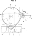
- Fig. 6 shows a second embodiment of the device for supplying a constant number of parts (the constant-number-of-parts-supplying device) according to the present invention. Same element or component as that in Fig. 2 is denoted by the same reference sign.
- a box-shaped stage 31 is provided, and the motor 12 and the controller 21 are accommodated in the stage 31.
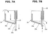
- a shutter-type output box 24 shown in Fig. 7 could be employed instead of the output plate 17 in Fig. 6 .
- a bottom portion 24a inclines downwards in a forward direction, and a shutter plate 25 having an opening 25a at a front side of the output box 24, where an opening 24b of the output box 24 opens at a lower portion of the output box 24, is disposed.
- the output box 24 stores the bolt (s) P until the number of bolts P reaches the constant number of bolts P.
- the stored bolt (s) P is (are) prevented from dropping by a section except the opening 25a of the shutter plate 25.
- the pushing operation of the reset switch 20 shown in Figs. 4 and 5 be done by a raising operation of the shutter plate 25.
- the small parts that are the object of the constant supply as an example, bolts P having a washer are shown.
- the small parts of the object of the constant supply are not limited to bolts. They could be parts having stem or shaft, step-shaped parts, and small parts such as washers.
- shape and magnitude of magnetic force of the magnets 6a, 6b and 15 and also shape of the separation chutes 11a, 11b should be properly determined depending on size and shape of the parts to be supplied.
- the present invention is not limited to this case. As long as the large-diameter disc 3 and the small-diameter discs 8a, 8b rotate together during the output of the small parts, the present invention can be achieved.
- the present invention includes a case where the large-diameter disc 3 and the small-diameter discs 8a, 8b independently rotate without synchronization.
Landscapes
- Engineering & Computer Science (AREA)
- Mechanical Engineering (AREA)
- Feeding Of Articles To Conveyors (AREA)
- Specific Conveyance Elements (AREA)
Abstract
Description
- The present invention relates to a device for supplying a constant number of parts, which counts a predetermined necessary number (constant number or constant amount) of small parts such as bolts and nuts existing in bulk (in random orientations and positions) and outputs the necessary number of small parts to a parts-output port located in a predetermined position.
- As this kind of device for supplying constant number of small parts,
Patent Documents - However, the prior art devices for supplying constant number of small parts disclosed in the
Patent Documents -
- Patent Document 1: Japanese Unexamined Utility Model Publication No.
7-13829 - Patent Document 2 : Japanese Unexamined Patent Publication No.
7-117859 - Patent Document 3: Japanese Unexamined Utility Model Publication No.
63-67544 - The present invention was made in view of the above technical problem. An object of the present invention is therefore to provide a device for supplying a constant number of parts, which improves the reliability of the output of the constant number of parts.
- A device for supplying constant number of parts of the present invention raises a small part attracted by a first magnet embedded in one side surface of a rotary large-diameter disc to an upper side, separates the small part from the first magnet by a separation chute disposed close to the large-diameter disc, and transfers the small part to the separation chute. A small-diameter disc that rotates together with the large-diameter disc is placed close to the separation chute, and the small-diameter disc attracts the small part existing on the separation chute to an outer circumferential surface of the small-diameter disc by a magnetic force of a second magnet that is embedded in the small-diameter disc. Further, a parts-output port is disposed at an opposite side to the separation chute with respect to the small-diameter disc, and the small part at the small-diameter disc side is separated at the parts-output port and transferred to the parts-output port side. Then, in a process of transfer of the small parts attracted to the small-diameter disc from the separation chute side to the parts-output port side, presence of the small parts, i.e. the number of small parts transferred to the parts-output port side, is detected by a detecting unit.
- According to the present invention, the small part attracted by the first magnet on the large-diameter disc side is separated once by the separation chute, and is attracted again by the second magnet on the small-diameter disc side, then is outputted to the parts-output port side. Accordingly, as compared with the case of the related art in which the small part attracted by the magnet is repeatedly limited by the plurality of guide plates, so-called output of two small parts can be excluded, and reliability of the output number of the small parts is improved. In addition, it is possible to greatly shorten a time of the trial required to formally launch the facilities.
-
- [
Fig. 1 ]
Fig.1 is a front view for explaining a first embodiment of a device for supplying a constant number of parts according to the present invention. - [
Fig. 2 ]
Fig.2 is a left side view for explaining the device for supplying constant number of parts shown inFig. 1 . - [
Fig. 3 ]
Fig. 3 is a perspective view showing relationship between a hopper and a large-diameter disc shown inFigs. 1 and2 . - [
Fig. 4 ]
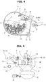
Fig. 4 is a drawing for explaining relationship between the large-diameter disc, a separation chute, a small-diameter disc, a guide chute and a parts-output plate shown inFigs. 1 and2 . - [
Fig. 5 ]
Fig. 5 is a perspective view showing relationship between main parts such as the separation chute, the small-diameter disc, the guide chute and the parts-output plate shown inFig. 4 . - [
Fig. 6 ]
Fig. 6 is a side view for explaining a second embodiment of the device for supplying constant number of parts according to the present invention. - [
Fig. 7 ]
Figs. 7A and 7B are drawings for explaining a structure of a parts-output box that replaces the parts-output plate ofFig. 6 . -
Figs. 1 to 5 show an embodiment for carrying out a device for supplying constant number of parts (a constant-number-of-parts-supplying device) of the present invention.Fig. 1 is a front view for explaining the whole device.Fig. 2 is a left side explanatory drawing of the device shown inFig. 1 . Further,Figs. 3 to 5 show details of main parts of the device shown inFig. 1 and2 . - The embodiment here shows a case where, for instance, the constant-number-of-parts-supplying device is provided at a line side of an assembly line for vehicle, and a constant number (constant amount) of bolts having a washer that is within a range of e.g. one to approx. ten (an arbitrary number of the bolts having the washer can be set), which is the required number of the bolts having the washer to assemble interior parts of a specific vehicle model by a worker according to a designated specification of the interior parts (the required number of bolt (s) having the washer for the assembly is different depending on the designated specification of the interior parts), is supplied.
- As shown in
Fig. 3 in addition toFigs. 1 and2 , a pair ofside plates bottom plate 1. Between theseside plates diameter disc 3 and a pair of almost quarterspherical hoppers 4 are set. The large-diameter disc 3 is rotatably supported on its both sides by the pair ofside plates 2 through ashaft 5. The pair ofhoppers 4 are disposed close to large-diameter disc 3, and set symmetrically at both sides (right and left sides) of the large-diameter disc 3. With these settings, as shown inFigs. 3 and4 , each hopper 4 forms, together with the large-diameter disc 3, an accommodation space for a number of bolts P having the washer (hereinafter, simply called bolts P) as the small parts that are an object of the constant supply. - Diameters of these large-
diameter disc 3 andhopper 4 are substantially the same, and both outlines are almost (or substantially) identical to each other when viewed from the side of the device as shown inFigs. 2 and4 . An upper opening of eachhopper 4 is positioned at an upper side with respect to theshaft 5. Then, as shown inFigs. 3 and4 , a number of bolts P are accommodated and stored in bulk (in random orientations and positions) in the accommodation spaces of bothhoppers 4. - The large-
diameter disc 3 is made of light metal, and a resin sheet (notshown) is pasted on both side surfaces, which the bolts P touch, of the large-diameter disc 3. The large-diameter disc 3 also serves as a pulley for an after-mentioned cogged belt (synchronous belt or toothed belt) 14, and a number of teeth (not shown) are formed on an outer circumferential surface of the large-diameter disc 3. A pair of short cylindrical magnets (permanent magnets) 6a, as first magnets, are embedded in one of the side surfaces of the large-diameter disc 3 in 180 degree phase positions at an outer circumferential side edge portion of the side surface. Likewise, a pair ofmagnets 6b, as first magnets, are embedded in the other of the side surfaces of the large-diameter disc 3 in 180 degree phase positions, which are shifted by 90 degrees from the phase positions of themagnets 6a embedded in the one side surface, at an outer circumferential side edge portion of the side surface. Thesemagnets diameter disc 3 so that themagnets diameter disc 3 form an even surface . As themagnets Figs. 3 and4 , when the large-diameter disc 3 rotates, one bolt P is attracted and held by themagnet diameter disc 3. - Here, a mixing (or stir or agitation) magnet (mixing permanent magnet) 7 is embedded in both side surfaces of the large-
diameter disc 3 in a center side position with respect to thebolt attraction magnets magnets 7 are not intended for attraction and raise of the bolt P, but are disposed for mixing the bolts P in the accommodation space of thehopper 4, i. e. the mixingmagnets 7 are intended for randomization of position (attitude) and direction (orientation) of each bolt P. In other words, the mixingmagnet 7 is a magnet that avoids a situation in which the plurality of bolts P having the washer become a relatively large mass of bolts by the washers and threads of the bolts P intertwining with each other, then the bolt P cannot be attracted by thebolt attraction magnets - Apair of small-
diameter discs diameter disc 3 at an upper side of the large-diameter disc 3 so that axes of the small-diameter discs diameter disc 3. As shown inFig. 5 , in addition toFigs. 1 and2 , these small-diameter discs diameter pulley 9 are coaxially arranged and integrally fixed to ashaft 10. Theshaft 10 is rotatably supported on its both sides by a stay (not shown) extending from theside plates 2. That is, in the front views ofFigs. 1 and5 , the small-diameter discs diameter disc 3. Further, as described later, between both upper side surfaces of the large-diameter disc 3 and the small-diameter discs separation chutes magnets diameter disc 3 side, are set like a spanning bridge (so as to span a space between the large-diameter disc 3 and the small-diameter discs separation chutes magnets diameter disc 3 side, and have downslope toward the small-diameter discs separation chutes diameter discs Fig. 4 , when the bolt P attracted and held by themagnet diameter disc 3 passes theseparation chute magnet separation chute separation chute diameter discs - On the
bottom plate 1 shown inFigs. 1 and2 , as a rotation drive unit or a rotation driver, amotor 12 having reduction gears is disposed. Then, thecogged belt 14, as a winding transmission unit or a winding transfer, is wound around adrive pulley 13 at a motor shaft side, thepulley 9 at the small-diameter disc diameter disc 3. With this setting, by start and operation of themotor 12, the large-diameter disc 3 and the small-diameter discs diameter disc 3 and the small-diameter discs motor 12, in order to be able to adjust a circle time required to output or take out the constant number of bolts P, a variable-speed type motor is desirable. - As shown in
Figs. 4 and 5 in addition toFigs. 1 and2 , a rod-like magnet (permanent magnet) 15, as a second magnet, is embedded in an outer circumferential edge portion of each of the small-diameter discs diameter discs magnets 15 embedded in one small-diameter disc 8a and the other small-diameter disc 8b are shifted by 180 degrees. Then, the speed ratio between the large-diameter disc 3 and the small-diameter discs separation chute diameter disc 3 side, themagnet 15 embedded in the small-diameter disc separation chute separation chute separation chute magnet 15 embedded in the outer circumferential surface of the small-diameter disc magnet 15 in the small-diameter disc separation chute separation chute diameter disc diameter disc 8a side and the other small-diameter disc 8b side. - An
output plate 17 as a parts-output port and aguide chute 16 that is an output chute of the bolt P are disposed at an opposite side to theseparation chute diameter discs output plate 17 and theguide chute 16 is fixed and supported by a stay (not shown) extending from thebottom plate 1 or theside plates 2. Both the small-diameter discs output plate 17 and guidechute 16. Theguide chute 16 is set with its upper end portion located close to both small-diameter discs output plate 17. Theoutput plate 17 is, for instance, a circular deep bowl, and this shape is considered so that ultimately the plurality of bolts P, which are supplied to theoutput plate 17 as the constant number of bolts P, can be grasped by worker's one-time one-hand grasping operation. Then, when the bolt P attracted and held by the outer circumferential surface of the small-diameter disc guide chute 16, the bolt P on the small-diameter disc guide chute 16 to theoutput plate 17, then is outputted. Such operation is alternately repeated at one small-diameter disc 8a side and the other small-diameter disc 8b side. - As explained above, in the present embodiment, as shown in
Figs. 1 ,3 and5 , thehoppers 4 are set symmetrically at both sides (right and left sides) of the common large-diameter disc 3, and mutuallyindependent separation chutes diameter discs diameter disc 3 while sharing the large-diameter disc 3, theguide chute 16 and theoutput plate 17. Here, in the present embodiment, although theguide chute 16 and theoutput plate 17 are separately provided, both of theguide chute 16 and theoutput plate 17 couldbe provided as an integral component, as necessary. - As shown in
Figs. 4 and 5 in addition toFigs. 1 and2 , as a noncontact detecting unit or detector, a through-beam type photoelectric (or optoelectronic)sensor 18 formed from a light projector (a phototransmitter) 18a and a light receiver (a photoreceiver) 18b is provided close to upper sides of the pair of small-diameter discs output completion lamp 19 and areset switch 20 such as a limit switch are provided close to theoutput plate 17. The constant number of bolts P (the number of bolts P) to be outputted to theoutput plate 17 is previously set as a setting value on an after-mentionedcontroller 21 side. Thus, each time the bolt P attracted and held by the outer circumferential surface of the small-diameter disc photoelectric sensor 18, one bolt P is detected by thephotoelectric sensor 18 as one bolt P outputted to theoutput plate 17. Further, when the number of bolts P outputted to theoutput plate 17 reaches the setting value, the rotation drive of the large-diameter disc 3 and the small-diameter discs motor 12 is immediately stopped, and at the same time, the above-mentioned constant numberoutput completion lamp 19 lights up. - In
Figs. 1 and2 , areference sign 21 is a controller, as a control unit, that performs total control of the constant-number-of-parts-supplying device configured above, especially performs start and operation control of themotor 12. Thephotoelectric sensor 18, the constant numberoutput completion lamp 19 and thereset switch 20 are connected to thecontroller 21. Here, as a higher controller of thecontroller 21, a parts-order unit 22 is provided. Further, as a higher controller of the parts-order unit 22, a high-endproduction management unit 23 is provided. - Next, a series of working or operation of the constant-number-of-parts-supplying device configured above will be explained.
- As shown in
Figs. 1 and2 , when themotor 12 is operated by a command from thecontroller 21, the large-diameter disc 3 and the small-diameter discs output plate 17 one by one through the large-diameter disc 3 and the small-diameter discs output plate 17 reaches the constant number (the setting value), the synchronous rotation of the large-diameter disc 3 and the small-diameter discs motor 12 is immediately stopped. - Here, in a case where specific interior parts of a specific vehicle model are assembled at a specific stage on an assembly line for vehicle and then the required number of the bolts for the assembly of the interior parts is different depending on a specification of the interior parts, information about the required number of bolts P for the assembly of the interior parts is given to the
controller 21 from the parts-order unit 22 on the basis of vehicle model information and spec information of the interior parts from the high-endproduction management unit 23, and the setting value of the number of bolts P (the constant number of bolts P) is set in thecontroller 21. In response to this set of the setting value of the number of bolts P, thecontroller 21 starts and operates themotor 12, and continuously rotate the large-diameter disc 3 and the small-diameter discs - As shown in
Figs. 3 and4 in addition toFigs. 1 and2 , when the large-diameter disc 3 positioned in the middle of the twohoppers left side hoppers magnet diameter disc 3. Subsequently, as shown inFigs. 4 and 5 , when the bolt P attracted and held by themagnet separation chute magnet separation chute separation chute separation chute - In this case, by properly determining the diameter and the magnetic force of the
magnets diameter disc 3 side, it is possible to avoid a situation in which the plurality of bolts P are attracted by thesingle magnet single magnet separation chute hopper 4. Moreover, even if the two bolts P should transfer to theseparation chute separation chute diameter disc - As shown in
Fig. 4 , when the bolt P transfers to theseparation chute separation chute diameter disc diameter disc magnet 15 embedded in the small-diameter disc separation chute diameter disc 3 and the small-diameter discs magnet 15 embedded in the small-diameter disc separation chute magnet diameter disc 3 to theseparation chute - Further, as shown in
Figs. 4 and 5 , when the bolt P attracted and held by the outer circumferential surface of the small-diameter disc guide chute 16 by the rotation of the small-diameter disc diameter disc guide chute 16 with the bolt P scraped off by theguide chute 16. With this working or operation, the bolt P having been attracted to the small-diameter disc guide chute 16 by its own weight, then finally the bolt P is outputted to the parts-output plate 17. - Here, as shown in
Fig. 5 showing an example of the bolt P attracted by the left side small-diameter disc 8a, the bolt P attracted to the small-diameter disc photoelectric sensor 18, which both the small-diameter discs guide chute 16, and momentarily intercepts or cuts off the optical axis of thephotoelectric sensor 18. With this, it is judged that one bolt P is outputted to the parts-output plate 17. By this detection output of thephotoelectric sensor 18, thecontroller 21 counts the number of bolts P outputted to the parts-output plate 17, and continues it until this count value reaches the setting value. Here, instead of thephotoelectric sensor 18, a sensor that senses the magnetic force of themagnet 15 attracting the bolt P on the outer circumferential surfaces of the small-diameter discs - Further, the two
magnets 6a are mounted on one of the side surfaces of the large-diameter disc 3 in 180 degree phase positions, while the twomagnets 6b are mounted on the other of the side surfaces of the large-diameter disc 3 in 180 degree phase positions which are shifted by 90 degrees with respect to the phase positions of themagnets 6a embedded in the one side surface, which is previously explained. - Accordingly, during the continuous synchronous rotation of the large-
diameter disc 3 and the small-diameter discs magnet diameter disc 3 to theseparation chute separation chute diameter disc diameter disc guide chute 16 are alternately repeated at one small-diameter disc 8a side and the other small-diameter disc 8b side. As a consequence, the output of one bolt P to the parts-output plate 17 is intermittently carried out. - Furthermore, as mentioned above, since the mixing
magnet 7 is mounted on both side surfaces of the large-diameter disc 3, the bolts P accommodated in thehoppers 4 are mixed by and according to the rotation of the large-diameter disc 3. This thus avoids the situation in which the bolts P having the washer become a relatively large mass of bolts by the washers and threads of the bolts P intertwining with each other, thereby stably outputting the bolt P one by one. - Then, when the bolt(s) P is(are) outputted to the parts-
output plate 17 by the setting number, which means that the count value of the bolt P in thecontroller 21 reaches the setting value, thecontroller 21 immediately stops the rotation of the large-diameter disc 3 and the small-diameter discs motor 12, and also turns on the above-mentioned constant numberoutput completion lamp 19. During rotation stop of the large-diameter disc 3 and the small-diameter discs magnets diameter disc 3, or although the bolt P remains on theseparation chutes output completion lamp 19 continues until the bolt (s) P in the parts-output plate 17 is (are) taken out. - Subsequently, the worker visually checks the lighting of the constant number
output completion lamp 19 and takes out all of the bolts P outputted to the parts-output plate 17, and pushes on thereset switch 20 for verification, then the device becomes an ON state. Only after receiving a signal from thereset switch 20, the constant numberoutput completion lamp 19 goes off, and the setting value of the number of bolts P and the count value (count number) are reset (clear) in thecontroller 21. Then, a series of working or operation with the setting of the number of bolts P being a first operation is repeated. - According to the constant-number-of-parts -supplying device of the present embodiment, besides the attraction of the bolt P by the
magnets diameter disc 3, the transfer movement of the bolt P from themagnets diameter disc 3 to theseparation chutes separation chutes diameter discs diameter discs guide chute 16 are alternately repeated at one small-diameter disc 8a side and the other small-diameter disc 8b side. Therefore, so-called output of two bolts P is excluded, and reliability of the output of one bolt P is improved, and it is consequently possible to greatly improve reliability of the output number of bolts P by the constant-number-of-parts-supplying device. - Further, the mixing
magnet 7 is provided at the large-diameter disc 3. This thus avoids the situation in which the bolts P having the washer become a relatively large mass of bolts by the washers and threads of the bolts P intertwining with each other, thereby stably outputting the bolt P one by one. - Moreover, both outlines of the quarter
spherical hoppers 4 and the large-diameter disc 3 are almost identical to each other when viewed from the side of the device, and themagnets diameter disc 3. Thus, even if the number of bolts P in the accommodation spaces of thehoppers 4 decreases, the bolts P in the accommodation spaces slide and drop so as to come to or approach themagnets diameter disc 3. As a consequence, even if only one bolt P remains in thehoppers 4, the one bolt P can be certainly attracted by themagnets - Furthermore, since output of the bolt P is alternately carried out in 180 degree phase positions on both sides of the large-
diameter disc 3, the circle time required to output or take out the constant number of bolts P becomes short, then output or take-out of the constant number of bolts P can be efficiently performed. In addition, thecogged belt 14 is used, as the winding transmission unit, for the synchronous rotation of the large-diameter disc 3 and the small-diameter discs diameter disc 3 and the small-diameter discs -
Fig. 6 shows a second embodiment of the device for supplying a constant number of parts (the constant-number-of-parts-supplying device) according to the present invention. Same element or component as that inFig. 2 is denoted by the same reference sign. - In the present embodiment, as can be understood from comparison between
Figs. 6 and2 , instead of thebottomplate 1 inFig. 2 , a box-shapedstage 31 is provided, and themotor 12 and thecontroller 21 are accommodated in thestage 31. - In this case, instead of the
output plate 17 inFig. 6 , a shutter-type output box 24 shown inFig. 7 could be employed. Regarding thisoutput box 24, as shown inFig. 7A , abottom portion 24a inclines downwards in a forward direction, and ashutter plate 25 having anopening 25a at a front side of theoutput box 24, where anopening 24b of theoutput box 24 opens at a lower portion of theoutput box 24, is disposed. Theoutput box 24 stores the bolt (s) P until the number of bolts P reaches the constant number of bolts P. The stored bolt (s) P is (are) prevented from dropping by a section except theopening 25a of theshutter plate 25. In a case where the worker takes out the bolt(s) P stored in theoutput box 24, as shown inFig. 7B , by raising theshutter plate 25 so that theopening 24b opens by opening of theopening 25a, the stored bolt (s) P slide (s) on or tumble (s) down thebottom portion 24a, then the worker takes out the bolt (s) P through theopenings - Here, it is preferable that the pushing operation of the
reset switch 20 shown inFigs. 4 and 5 be done by a raising operation of theshutter plate 25. - In the above embodiments, as the small parts that are the object of the constant supply, as an example, bolts P having a washer are shown. However, the small parts of the object of the constant supply are not limited to bolts. They could be parts having stem or shaft, step-shaped parts, and small parts such as washers. Here, it is desirable that shape and magnitude of magnetic force of the
magnets separation chutes - Further, although the above embodiments show a case where the large-
diameter disc 3 and the small-diameter discs belt 14, the present invention is not limited to this case. As long as the large-diameter disc 3 and the small-diameter discs diameter disc 3 and the small-diameter discs
Claims (9)
- A device for supplying constant number of small parts comprising:a large-diameter disc driven and rotating on a horizontal axis thereof;a hopper disposed close to the large-diameter disc at at least a lower half side of one of side surfaces of the large-diameter disc, the hopper accommodating therein the small parts in bulk;a first magnet embedded in the one side surface of the large-diameter disc so as to be exposed at the one side surface of the large-diameter disc, the first magnet attracting, at an outer circumferential side edge portion of the one side surface of the large-diameter disc, one small part accommodated in an accommodation space of the hopper;a small-diameter disc disposed close to the large-diameter disc at an upper side of the large-diameter disc so that an axis of the small-diameter disc is parallel to the axis of the large-diameter disc, the small-diameter disc driven and rotating on axis thereof;a separation chute disposedbetween the large-diameter disc and the small-diameter disc so as to span a space between the large-diameter disc and the small-diameter disc, the separation chute separating the small part, which is attracted to the large-diameter disc by the first magnet, from the large-diameter disc and receiving the small part;a second magnet embedded in the small-diameter disc, the second magnet attracting, on an outer circumferential surface of the small-diameter disc, the small part that is on the separation chute;a parts-output port disposed close to the small-diameter disc at an opposite side to the separation chute with respect to the small-diameter disc, the parts-output port separating the small part, which is attracted to the small-diameter disc, from the small-diameter disc and outputting the small part;a rotation driver driving rotation of the large-diameter disc and the small-diameter disc;a detector detecting the small parts outputted to the parts-output port, the detector performing the detection of the small part while the small part is being attracted on the outer circumferential surface of the small-diameter disc; anda controller controlling a drive control of the rotation driver, capable of setting arbitrary number of the small parts to be outputted to the parts-output port, counting the number of the small parts outputted to the parts-output port by an output of the detector, and stopping the rotation driver at a time when a count number reaches a setting value.
- The device for supplying constant number of small parts as claimed in claim 1, wherein:the large-diameter disc and the small-diameter disc are driven and rotate in synchronization with each other by the rotation driver.
- The device for supplying constant number of small parts as claimed in claim 2, wherein:two first magnets are disposed at the large-diameter disc with phase positions of the two first magnets shifted to each other by 180 degrees in a rotation direction of the large-diameter disc.
- The device for supplying constant number of small parts as claimed in claim 3, wherein:a mixing magnet is embedded in the one side surface of the large-diameter disc in a center side position with respect to the first magnets, andthe mixing magnet mixes the small parts accommodated in bulk in the hopper by an attraction force of the mixing magnet when the large-diameter disc rotates.
- The device for supplying constant number of small parts as claimed in claim 4, wherein:the hoppers, the separation chutes and the small-diameter discs are symmetrically provided at both sides of the large-diameter disc respectively,the first magnet and the mixing magnet are embedded in the other of the side surfaces of the large-diameter disc with phase positions of the first magnet and the mixing magnet shifted with respect to respective phase positions of the first magnet and the mixing magnet embedded in the one side surface of the large-diameter disc,the second magnet is embedded in each of the small-diameter discs, and phase positions of the second magnets are shifted to each other in a rotation direction of the small-diameter discs,both the small-diameter discs share the common parts-output port and a common noncontact sensor as the detector, andthe small parts accommodated in both the accommodation spaces of the hoppers are alternately outputted to the common parts-output port through the large-diameter disc and both the small-diameter discs.
- The device for supplying constant number of small parts as claimed in claim 5, wherein:the phase position of the second magnet of the one small-diameter disc and the phase position of the second magnet of the other small-diameter disc are shifted to each other by 180 degrees in the rotation direction of the small-diameter discs.
- The device for supplying constant number of small parts as claimed in claim 5, wherein:a winding transfer is wound around a shaft, which the pair of small-diameter discs share, and an outer circumferential surface of the large-diameter disc, and the large-diameter disc and the pair of small-diameter discs are driven and rotate in synchronization with each other by the rotation driver through the winding transfer.
- The device for supplying constant number of small parts as claimed in claim 7, wherein:the hopper has a substantially quarter spherical shape, and a projected outline of the hopper and a projected outline of the large-diameter disc, which are viewed from an axis direction of the large-diameter disc, are substantially identical to each other.
- The device for supplying constant number of small parts as claimed in any one of the preceding claims 1 to 8, wherein:the small parts are bolts.
Applications Claiming Priority (2)
| Application Number | Priority Date | Filing Date | Title |
|---|---|---|---|
| JP2013132176 | 2013-06-25 | ||
| PCT/JP2014/061400 WO2014208187A1 (en) | 2013-06-25 | 2014-04-23 | Device for supplying constant number of small parts |
Publications (3)
| Publication Number | Publication Date |
|---|---|
| EP3015407A1 true EP3015407A1 (en) | 2016-05-04 |
| EP3015407A4 EP3015407A4 (en) | 2016-06-08 |
| EP3015407B1 EP3015407B1 (en) | 2017-06-07 |
Family
ID=52141541
Family Applications (1)
| Application Number | Title | Priority Date | Filing Date |
|---|---|---|---|
| EP14816103.7A Active EP3015407B1 (en) | 2013-06-25 | 2014-04-23 | Device for supplying constant number of small parts |
Country Status (6)
| Country | Link |
|---|---|
| US (1) | US9457437B2 (en) |
| EP (1) | EP3015407B1 (en) |
| JP (1) | JP5987986B2 (en) |
| CN (1) | CN105339287B (en) |
| MX (1) | MX345488B (en) |
| WO (1) | WO2014208187A1 (en) |
Cited By (1)
| Publication number | Priority date | Publication date | Assignee | Title |
|---|---|---|---|---|
| US11167928B2 (en) * | 2020-02-21 | 2021-11-09 | Toyota Jidosha Kabushiki Kaisha | Bolt supply device |
Families Citing this family (10)
| Publication number | Priority date | Publication date | Assignee | Title |
|---|---|---|---|---|
| WO2014208187A1 (en) * | 2013-06-25 | 2014-12-31 | 日産自動車株式会社 | Device for supplying constant number of small parts |
| JP6467619B2 (en) * | 2014-06-23 | 2019-02-13 | パナソニックIpマネジメント株式会社 | Screw mounting device |
| JP6232585B2 (en) * | 2014-06-23 | 2017-11-22 | パナソニックIpマネジメント株式会社 | Screw supply device |
| CN105394025B (en) * | 2015-09-21 | 2018-08-21 | 江苏大学 | A kind of degradable sphere automatic release device of unmanned plane |
| JP6612681B2 (en) * | 2016-06-03 | 2019-11-27 | トヨタ自動車株式会社 | Rivet feeder |
| KR101813137B1 (en) * | 2016-10-17 | 2017-12-28 | 성화내진전착볼트 주식회사 | An automatic supply device for all screw type bolt |
| CN106736387B (en) * | 2017-02-16 | 2019-05-03 | 中山职业技术学院 | Magnetic sheet feeding device for assembling magnetic attraction column of LED lamp |
| CN109514224A (en) * | 2018-12-24 | 2019-03-26 | Tcl王牌电器(惠州)有限公司 | Pick pin structure and automatic tapping machine |
| JP7238831B2 (en) * | 2020-02-21 | 2023-03-14 | トヨタ自動車株式会社 | bolt feeder |
| FR3132087B1 (en) * | 2022-01-26 | 2024-01-05 | Psa Automobiles Sa | Portable screw or nut dispenser. |
Family Cites Families (38)
| Publication number | Priority date | Publication date | Assignee | Title |
|---|---|---|---|---|
| US3054170A (en) * | 1960-03-14 | 1962-09-18 | Kazmier Wysocki | Device for automatically orienting, delivering and inserting combined valve and dip tube in aerosol containers |
| US3065841A (en) * | 1961-01-05 | 1962-11-27 | Anchor Hocking Glass Corp | Selector hopper |
| DE1481376A1 (en) * | 1967-03-23 | 1969-11-20 | Modrey Dr Henry John | Device for separating, aligning and dispensing small items |
| CH508539A (en) * | 1969-06-28 | 1971-06-15 | Coster Tecnologie Speciali Spa | Apparatus for taking valves equipped with a suction tube for aerosol containers from a tank and conveying them to a collection guide |
| US3674141A (en) * | 1970-12-21 | 1972-07-04 | Western Electric Co | Article handling with fluid ejection |
| US3863802A (en) * | 1971-02-12 | 1975-02-04 | Continental Can Co | Cap feeding hopper |
| US3741436A (en) * | 1971-05-14 | 1973-06-26 | Western Electric Co | Handling of magnetically asymmetrical articles |
| US3731783A (en) * | 1971-11-08 | 1973-05-08 | Western Electric Co | Methods and apparatus for sorting articles |
| US3862536A (en) * | 1973-03-21 | 1975-01-28 | Gte Automatic Electric Lab Inc | High speed loading of reedblades |
| US3877577A (en) * | 1973-10-29 | 1975-04-15 | Wilton Richard | Culinary articles and apparatus for retrieving and/or sorting the same |
| DE2542827A1 (en) * | 1975-09-25 | 1977-04-07 | Siemens Ag | Rotary sorting machine for cylindrical magnetic components - has permanent magnets on vertical rotor plate, releasing correctly aligned cylinders |
| US4047637A (en) * | 1976-12-03 | 1977-09-13 | Minnesota Mining And Manufacturing Company | Paper clip dispenser |
| DE2833424A1 (en) * | 1978-07-29 | 1980-02-07 | Agfa Gevaert Ag | Metal part feed mechanism - has magnets on disc close to bottom of inclined drum and movable past selector for ejection of incorrectly positioned parts |
| US4300462A (en) * | 1979-05-30 | 1981-11-17 | The United States Of America As Represented By The Secretary Of Agriculture | Apparatus for planting seeds |
| US4453575A (en) * | 1982-02-05 | 1984-06-12 | Hi-Speed Checkweigher Co., Inc. | Container filling system |
| JPH0432366Y2 (en) | 1986-10-24 | 1992-08-04 | ||
| JP2559280B2 (en) | 1989-11-30 | 1996-12-04 | 堀江金属工業株式会社 | Front and back aligning device for magnetic ring materials |
| US5078300A (en) * | 1990-03-12 | 1992-01-07 | Nick Heu | Stationery case with magnetic wheel dispenser |
| US5096091A (en) * | 1990-03-20 | 1992-03-17 | Nick Heu | Magnetic roller paper clip dispenser |
| WO1994021449A1 (en) * | 1993-03-19 | 1994-09-29 | Bedford Industries, Inc. | Apparatus and method for applying a twist-tie to a packaging container |
| JPH0713829U (en) * | 1993-08-20 | 1995-03-10 | 株式会社シンワ | Constant supply device for parts such as nuts |
| JPH07117859A (en) | 1993-10-29 | 1995-05-09 | Toyota Tekko Kk | Fixed quantity feeder for two kinds of parts |
| US5529208A (en) * | 1994-12-30 | 1996-06-25 | Technik Mfg., Inc. | Jar ticket dispensing apparatus and method |
| US5702030A (en) * | 1996-01-11 | 1997-12-30 | The Boeing Company | Rotational arm-type contact feeding system |
| KR0156406B1 (en) * | 1996-09-18 | 1999-01-15 | 양재신 | Bolt counter |
| US6345714B1 (en) * | 2000-05-12 | 2002-02-12 | Deere & Company | Part sorting and aligning apparatus |
| DE10029511A1 (en) * | 2000-06-21 | 2002-01-17 | Alcoa Deutschland Gmbh | Feed unit for a container closing device |
| US6790412B2 (en) * | 2001-02-06 | 2004-09-14 | Beckman Coulter, Inc. | Bulk vessel feeder |
| US20030205028A1 (en) * | 2002-04-22 | 2003-11-06 | Sus Gerald A. | Automated food processing system and method |
| US6786358B1 (en) * | 2002-11-08 | 2004-09-07 | Hiromori Inc. | Clip case |
| US7166034B2 (en) * | 2004-02-26 | 2007-01-23 | Steven Wayne Hines | Golf ball dispensing and teeing device |
| JP2006143340A (en) * | 2004-11-16 | 2006-06-08 | Toyota Auto Body Co Ltd | Quantitative feeder |
| JP5350887B2 (en) * | 2009-02-13 | 2013-11-27 | 株式会社大武ルート工業 | Screw supply device |
| US8479671B2 (en) * | 2010-08-30 | 2013-07-09 | David T. Shoup | Magnetic vacuum seed meter |
| JP2012224460A (en) | 2011-04-21 | 2012-11-15 | Shimonishi Seisakusho:Kk | Magnet conveyer |
| JP5852352B2 (en) * | 2011-08-02 | 2016-02-03 | カルソニックカンセイ株式会社 | Nut metering device |
| US9096391B2 (en) * | 2012-12-04 | 2015-08-04 | Toyota Motor Engineering & Manufacturing North America, Inc. | Article dispenser apparatus |
| WO2014208187A1 (en) * | 2013-06-25 | 2014-12-31 | 日産自動車株式会社 | Device for supplying constant number of small parts |
-
2014
- 2014-04-23 WO PCT/JP2014/061400 patent/WO2014208187A1/en not_active Ceased
- 2014-04-23 EP EP14816103.7A patent/EP3015407B1/en active Active
- 2014-04-23 US US14/392,204 patent/US9457437B2/en active Active
- 2014-04-23 CN CN201480036495.1A patent/CN105339287B/en active Active
- 2014-04-23 JP JP2015523905A patent/JP5987986B2/en active Active
- 2014-04-23 MX MX2015017716A patent/MX345488B/en active IP Right Grant
Cited By (1)
| Publication number | Priority date | Publication date | Assignee | Title |
|---|---|---|---|---|
| US11167928B2 (en) * | 2020-02-21 | 2021-11-09 | Toyota Jidosha Kabushiki Kaisha | Bolt supply device |
Also Published As
| Publication number | Publication date |
|---|---|
| CN105339287A (en) | 2016-02-17 |
| JPWO2014208187A1 (en) | 2017-02-23 |
| MX345488B (en) | 2017-02-02 |
| US20160136765A1 (en) | 2016-05-19 |
| CN105339287B (en) | 2017-09-08 |
| EP3015407B1 (en) | 2017-06-07 |
| WO2014208187A1 (en) | 2014-12-31 |
| JP5987986B2 (en) | 2016-09-07 |
| MX2015017716A (en) | 2016-04-04 |
| EP3015407A4 (en) | 2016-06-08 |
| US9457437B2 (en) | 2016-10-04 |
Similar Documents
| Publication | Publication Date | Title |
|---|---|---|
| EP3015407B1 (en) | Device for supplying constant number of small parts | |
| US10772803B2 (en) | Medicine feeder and tablet splitting apparatus | |
| EP2626588A1 (en) | Electromagnetic brake system and force sense imparting type rotation input apparatus using the same | |
| KR101204723B1 (en) | Diaphragm device, camera, manufacturing method of diaphragm device, electronic equipment and mobile body drive device | |
| EP3424604A2 (en) | Method of in-line testing devices and testing apparatus | |
| US9916709B2 (en) | Coin batch insertion device | |
| EP1791095A3 (en) | Coin delivery device and coin delivery device of coin processing apparatus | |
| JP2017136671A (en) | Screw storage body, screw feeding device and method for manufacturing screw fastening matter | |
| CN209758450U (en) | Tray rotation driving device | |
| US20150008166A1 (en) | Sifting and grading device | |
| CN108961981A (en) | A kind of multi-functional real training robot having warning function | |
| CN102601062B (en) | Device and method for automatically discriminating pure-color objects with different colors | |
| JP4972039B2 (en) | Game ball sorting device | |
| CN212975921U (en) | Jewelry sorting and carrying equipment | |
| JP5634719B2 (en) | Hoppers and weighing equipment | |
| JP3901993B2 (en) | Handling device | |
| US20260021974A1 (en) | Transporting Device, System and Associated Method | |
| JPH07237735A (en) | Electronic component alignment device | |
| CN110550277B (en) | Use automatic card equipment of throwing on production line | |
| IT202100032747A1 (en) | CRIMPING DEVICE FOR TERMINAL TUBES | |
| EP1460589A3 (en) | Coin selecting machine with improved dragging system | |
| JPH0678655U (en) | Rack and pinion meshing mechanism | |
| JP2005324941A5 (en) | ||
| RU145512U1 (en) | DEVICE FOR WINDING MICROINDUCTIVES | |
| JP2000135330A (en) | Pachinko machine |
Legal Events
| Date | Code | Title | Description |
|---|---|---|---|
| PUAI | Public reference made under article 153(3) epc to a published international application that has entered the european phase |
Free format text: ORIGINAL CODE: 0009012 |
|
| 17P | Request for examination filed |
Effective date: 20160119 |
|
| AK | Designated contracting states |
Kind code of ref document: A1 Designated state(s): AL AT BE BG CH CY CZ DE DK EE ES FI FR GB GR HR HU IE IS IT LI LT LU LV MC MK MT NL NO PL PT RO RS SE SI SK SM TR |
|
| AX | Request for extension of the european patent |
Extension state: BA ME |
|
| A4 | Supplementary search report drawn up and despatched |
Effective date: 20160511 |
|
| RIC1 | Information provided on ipc code assigned before grant |
Ipc: B65G 65/48 20060101ALI20160504BHEP Ipc: B23P 19/06 20060101ALI20160504BHEP Ipc: B65G 47/86 20060101ALI20160504BHEP Ipc: B65G 47/14 20060101AFI20160504BHEP Ipc: B23P 19/00 20060101ALI20160504BHEP |
|
| DAX | Request for extension of the european patent (deleted) | ||
| GRAP | Despatch of communication of intention to grant a patent |
Free format text: ORIGINAL CODE: EPIDOSNIGR1 |
|
| STAA | Information on the status of an ep patent application or granted ep patent |
Free format text: STATUS: GRANT OF PATENT IS INTENDED |
|
| INTG | Intention to grant announced |
Effective date: 20170228 |
|
| GRAS | Grant fee paid |
Free format text: ORIGINAL CODE: EPIDOSNIGR3 |
|
| AK | Designated contracting states |
Kind code of ref document: B1 Designated state(s): AL AT BE BG CH CY CZ DE DK EE ES FI FR GB GR HR HU IE IS IT LI LT LU LV MC MK MT NL NO PL PT RO RS SE SI SK SM TR |
|
| REG | Reference to a national code |
Ref country code: GB Ref legal event code: FG4D |
|
| GRAA | (expected) grant |
Free format text: ORIGINAL CODE: 0009210 |
|
| REG | Reference to a national code |
Ref country code: CH Ref legal event code: EP Ref country code: AT Ref legal event code: REF Ref document number: 899059 Country of ref document: AT Kind code of ref document: T Effective date: 20170615 |
|
| STAA | Information on the status of an ep patent application or granted ep patent |
Free format text: STATUS: THE PATENT HAS BEEN GRANTED |
|
| REG | Reference to a national code |
Ref country code: IE Ref legal event code: FG4D |
|
| REG | Reference to a national code |
Ref country code: DE Ref legal event code: R096 Ref document number: 602014010621 Country of ref document: DE |
|
| REG | Reference to a national code |
Ref country code: NL Ref legal event code: MP Effective date: 20170607 |
|
| REG | Reference to a national code |
Ref country code: LT Ref legal event code: MG4D |
|
| PG25 | Lapsed in a contracting state [announced via postgrant information from national office to epo] |
Ref country code: NO Free format text: LAPSE BECAUSE OF FAILURE TO SUBMIT A TRANSLATION OF THE DESCRIPTION OR TO PAY THE FEE WITHIN THE PRESCRIBED TIME-LIMIT Effective date: 20170907 Ref country code: ES Free format text: LAPSE BECAUSE OF FAILURE TO SUBMIT A TRANSLATION OF THE DESCRIPTION OR TO PAY THE FEE WITHIN THE PRESCRIBED TIME-LIMIT Effective date: 20170607 Ref country code: HR Free format text: LAPSE BECAUSE OF FAILURE TO SUBMIT A TRANSLATION OF THE DESCRIPTION OR TO PAY THE FEE WITHIN THE PRESCRIBED TIME-LIMIT Effective date: 20170607 Ref country code: GR Free format text: LAPSE BECAUSE OF FAILURE TO SUBMIT A TRANSLATION OF THE DESCRIPTION OR TO PAY THE FEE WITHIN THE PRESCRIBED TIME-LIMIT Effective date: 20170908 Ref country code: FI Free format text: LAPSE BECAUSE OF FAILURE TO SUBMIT A TRANSLATION OF THE DESCRIPTION OR TO PAY THE FEE WITHIN THE PRESCRIBED TIME-LIMIT Effective date: 20170607 Ref country code: LT Free format text: LAPSE BECAUSE OF FAILURE TO SUBMIT A TRANSLATION OF THE DESCRIPTION OR TO PAY THE FEE WITHIN THE PRESCRIBED TIME-LIMIT Effective date: 20170607 |
|
| REG | Reference to a national code |
Ref country code: AT Ref legal event code: MK05 Ref document number: 899059 Country of ref document: AT Kind code of ref document: T Effective date: 20170607 |
|
| PG25 | Lapsed in a contracting state [announced via postgrant information from national office to epo] |
Ref country code: SE Free format text: LAPSE BECAUSE OF FAILURE TO SUBMIT A TRANSLATION OF THE DESCRIPTION OR TO PAY THE FEE WITHIN THE PRESCRIBED TIME-LIMIT Effective date: 20170607 Ref country code: BG Free format text: LAPSE BECAUSE OF FAILURE TO SUBMIT A TRANSLATION OF THE DESCRIPTION OR TO PAY THE FEE WITHIN THE PRESCRIBED TIME-LIMIT Effective date: 20170907 Ref country code: RS Free format text: LAPSE BECAUSE OF FAILURE TO SUBMIT A TRANSLATION OF THE DESCRIPTION OR TO PAY THE FEE WITHIN THE PRESCRIBED TIME-LIMIT Effective date: 20170607 Ref country code: LV Free format text: LAPSE BECAUSE OF FAILURE TO SUBMIT A TRANSLATION OF THE DESCRIPTION OR TO PAY THE FEE WITHIN THE PRESCRIBED TIME-LIMIT Effective date: 20170607 Ref country code: NL Free format text: LAPSE BECAUSE OF FAILURE TO SUBMIT A TRANSLATION OF THE DESCRIPTION OR TO PAY THE FEE WITHIN THE PRESCRIBED TIME-LIMIT Effective date: 20170607 |
|
| PG25 | Lapsed in a contracting state [announced via postgrant information from national office to epo] |
Ref country code: EE Free format text: LAPSE BECAUSE OF FAILURE TO SUBMIT A TRANSLATION OF THE DESCRIPTION OR TO PAY THE FEE WITHIN THE PRESCRIBED TIME-LIMIT Effective date: 20170607 Ref country code: RO Free format text: LAPSE BECAUSE OF FAILURE TO SUBMIT A TRANSLATION OF THE DESCRIPTION OR TO PAY THE FEE WITHIN THE PRESCRIBED TIME-LIMIT Effective date: 20170607 Ref country code: SK Free format text: LAPSE BECAUSE OF FAILURE TO SUBMIT A TRANSLATION OF THE DESCRIPTION OR TO PAY THE FEE WITHIN THE PRESCRIBED TIME-LIMIT Effective date: 20170607 Ref country code: AT Free format text: LAPSE BECAUSE OF FAILURE TO SUBMIT A TRANSLATION OF THE DESCRIPTION OR TO PAY THE FEE WITHIN THE PRESCRIBED TIME-LIMIT Effective date: 20170607 Ref country code: CZ Free format text: LAPSE BECAUSE OF FAILURE TO SUBMIT A TRANSLATION OF THE DESCRIPTION OR TO PAY THE FEE WITHIN THE PRESCRIBED TIME-LIMIT Effective date: 20170607 |
|
| PG25 | Lapsed in a contracting state [announced via postgrant information from national office to epo] |
Ref country code: IS Free format text: LAPSE BECAUSE OF FAILURE TO SUBMIT A TRANSLATION OF THE DESCRIPTION OR TO PAY THE FEE WITHIN THE PRESCRIBED TIME-LIMIT Effective date: 20171007 Ref country code: SM Free format text: LAPSE BECAUSE OF FAILURE TO SUBMIT A TRANSLATION OF THE DESCRIPTION OR TO PAY THE FEE WITHIN THE PRESCRIBED TIME-LIMIT Effective date: 20170607 Ref country code: PL Free format text: LAPSE BECAUSE OF FAILURE TO SUBMIT A TRANSLATION OF THE DESCRIPTION OR TO PAY THE FEE WITHIN THE PRESCRIBED TIME-LIMIT Effective date: 20170607 Ref country code: IT Free format text: LAPSE BECAUSE OF FAILURE TO SUBMIT A TRANSLATION OF THE DESCRIPTION OR TO PAY THE FEE WITHIN THE PRESCRIBED TIME-LIMIT Effective date: 20170607 |
|
| REG | Reference to a national code |
Ref country code: DE Ref legal event code: R097 Ref document number: 602014010621 Country of ref document: DE |
|
| REG | Reference to a national code |
Ref country code: FR Ref legal event code: PLFP Year of fee payment: 5 |
|
| PLBE | No opposition filed within time limit |
Free format text: ORIGINAL CODE: 0009261 |
|
| STAA | Information on the status of an ep patent application or granted ep patent |
Free format text: STATUS: NO OPPOSITION FILED WITHIN TIME LIMIT |
|
| PG25 | Lapsed in a contracting state [announced via postgrant information from national office to epo] |
Ref country code: DK Free format text: LAPSE BECAUSE OF FAILURE TO SUBMIT A TRANSLATION OF THE DESCRIPTION OR TO PAY THE FEE WITHIN THE PRESCRIBED TIME-LIMIT Effective date: 20170607 |
|
| 26N | No opposition filed |
Effective date: 20180308 |
|
| PG25 | Lapsed in a contracting state [announced via postgrant information from national office to epo] |
Ref country code: SI Free format text: LAPSE BECAUSE OF FAILURE TO SUBMIT A TRANSLATION OF THE DESCRIPTION OR TO PAY THE FEE WITHIN THE PRESCRIBED TIME-LIMIT Effective date: 20170607 |
|
| PG25 | Lapsed in a contracting state [announced via postgrant information from national office to epo] |
Ref country code: MC Free format text: LAPSE BECAUSE OF FAILURE TO SUBMIT A TRANSLATION OF THE DESCRIPTION OR TO PAY THE FEE WITHIN THE PRESCRIBED TIME-LIMIT Effective date: 20170607 |
|
| REG | Reference to a national code |
Ref country code: CH Ref legal event code: PL |
|
| REG | Reference to a national code |
Ref country code: BE Ref legal event code: MM Effective date: 20180430 |
|
| REG | Reference to a national code |
Ref country code: IE Ref legal event code: MM4A |
|
| PG25 | Lapsed in a contracting state [announced via postgrant information from national office to epo] |
Ref country code: LU Free format text: LAPSE BECAUSE OF NON-PAYMENT OF DUE FEES Effective date: 20180423 |
|
| PG25 | Lapsed in a contracting state [announced via postgrant information from national office to epo] |
Ref country code: BE Free format text: LAPSE BECAUSE OF NON-PAYMENT OF DUE FEES Effective date: 20180430 Ref country code: CH Free format text: LAPSE BECAUSE OF NON-PAYMENT OF DUE FEES Effective date: 20180430 Ref country code: LI Free format text: LAPSE BECAUSE OF NON-PAYMENT OF DUE FEES Effective date: 20180430 |
|
| PG25 | Lapsed in a contracting state [announced via postgrant information from national office to epo] |
Ref country code: IE Free format text: LAPSE BECAUSE OF NON-PAYMENT OF DUE FEES Effective date: 20180423 |
|
| PG25 | Lapsed in a contracting state [announced via postgrant information from national office to epo] |
Ref country code: MT Free format text: LAPSE BECAUSE OF NON-PAYMENT OF DUE FEES Effective date: 20180423 |
|
| PG25 | Lapsed in a contracting state [announced via postgrant information from national office to epo] |
Ref country code: TR Free format text: LAPSE BECAUSE OF FAILURE TO SUBMIT A TRANSLATION OF THE DESCRIPTION OR TO PAY THE FEE WITHIN THE PRESCRIBED TIME-LIMIT Effective date: 20170607 |
|
| PG25 | Lapsed in a contracting state [announced via postgrant information from national office to epo] |
Ref country code: PT Free format text: LAPSE BECAUSE OF FAILURE TO SUBMIT A TRANSLATION OF THE DESCRIPTION OR TO PAY THE FEE WITHIN THE PRESCRIBED TIME-LIMIT Effective date: 20170607 |
|
| PG25 | Lapsed in a contracting state [announced via postgrant information from national office to epo] |
Ref country code: CY Free format text: LAPSE BECAUSE OF FAILURE TO SUBMIT A TRANSLATION OF THE DESCRIPTION OR TO PAY THE FEE WITHIN THE PRESCRIBED TIME-LIMIT Effective date: 20170607 Ref country code: MK Free format text: LAPSE BECAUSE OF NON-PAYMENT OF DUE FEES Effective date: 20170607 Ref country code: HU Free format text: LAPSE BECAUSE OF FAILURE TO SUBMIT A TRANSLATION OF THE DESCRIPTION OR TO PAY THE FEE WITHIN THE PRESCRIBED TIME-LIMIT; INVALID AB INITIO Effective date: 20140423 |
|
| PG25 | Lapsed in a contracting state [announced via postgrant information from national office to epo] |
Ref country code: AL Free format text: LAPSE BECAUSE OF FAILURE TO SUBMIT A TRANSLATION OF THE DESCRIPTION OR TO PAY THE FEE WITHIN THE PRESCRIBED TIME-LIMIT Effective date: 20170607 |
|
| REG | Reference to a national code |
Ref country code: DE Ref legal event code: R084 Ref document number: 602014010621 Country of ref document: DE |
|
| REG | Reference to a national code |
Ref country code: GB Ref legal event code: 746 Effective date: 20230926 |
|
| PGFP | Annual fee paid to national office [announced via postgrant information from national office to epo] |
Ref country code: DE Payment date: 20250319 Year of fee payment: 12 |
|
| PGFP | Annual fee paid to national office [announced via postgrant information from national office to epo] |
Ref country code: GB Payment date: 20260319 Year of fee payment: 13 |
|
| PGFP | Annual fee paid to national office [announced via postgrant information from national office to epo] |
Ref country code: FR Payment date: 20260319 Year of fee payment: 13 |