EP3015365A1 - Unmanned helicopter - Google Patents
Unmanned helicopter Download PDFInfo
- Publication number
- EP3015365A1 EP3015365A1 EP14817182.0A EP14817182A EP3015365A1 EP 3015365 A1 EP3015365 A1 EP 3015365A1 EP 14817182 A EP14817182 A EP 14817182A EP 3015365 A1 EP3015365 A1 EP 3015365A1
- Authority
- EP
- European Patent Office
- Prior art keywords
- shaft
- elastic member
- drive shaft
- drive
- shaft portion
- Prior art date
- Legal status (The legal status is an assumption and is not a legal conclusion. Google has not performed a legal analysis and makes no representation as to the accuracy of the status listed.)
- Granted
Links
Images


Classifications
-
- B—PERFORMING OPERATIONS; TRANSPORTING
- B64—AIRCRAFT; AVIATION; COSMONAUTICS
- B64C—AEROPLANES; HELICOPTERS
- B64C27/00—Rotorcraft; Rotors peculiar thereto
- B64C27/82—Rotorcraft; Rotors peculiar thereto characterised by the provision of an auxiliary rotor or fluid-jet device for counter-balancing lifting rotor torque or changing direction of rotorcraft
-
- B—PERFORMING OPERATIONS; TRANSPORTING
- B64—AIRCRAFT; AVIATION; COSMONAUTICS
- B64C—AEROPLANES; HELICOPTERS
- B64C27/00—Rotorcraft; Rotors peculiar thereto
- B64C27/04—Helicopters
- B64C27/12—Rotor drives
- B64C27/14—Direct drive between power plant and rotor hub
-
- B—PERFORMING OPERATIONS; TRANSPORTING
- B64—AIRCRAFT; AVIATION; COSMONAUTICS
- B64U—UNMANNED AERIAL VEHICLES [UAV]; EQUIPMENT THEREFOR
- B64U10/00—Type of UAV
- B64U10/10—Rotorcrafts
-
- B—PERFORMING OPERATIONS; TRANSPORTING
- B64—AIRCRAFT; AVIATION; COSMONAUTICS
- B64U—UNMANNED AERIAL VEHICLES [UAV]; EQUIPMENT THEREFOR
- B64U30/00—Means for producing lift; Empennages; Arrangements thereof
- B64U30/20—Rotors; Rotor supports
-
- B—PERFORMING OPERATIONS; TRANSPORTING
- B64—AIRCRAFT; AVIATION; COSMONAUTICS
- B64U—UNMANNED AERIAL VEHICLES [UAV]; EQUIPMENT THEREFOR
- B64U50/00—Propulsion; Power supply
- B64U50/10—Propulsion
- B64U50/11—Propulsion using internal combustion piston engines
-
- B—PERFORMING OPERATIONS; TRANSPORTING
- B64—AIRCRAFT; AVIATION; COSMONAUTICS
- B64U—UNMANNED AERIAL VEHICLES [UAV]; EQUIPMENT THEREFOR
- B64U50/00—Propulsion; Power supply
- B64U50/30—Supply or distribution of electrical power
- B64U50/32—Supply or distribution of electrical power generated by fuel cells
-
- B—PERFORMING OPERATIONS; TRANSPORTING
- B64—AIRCRAFT; AVIATION; COSMONAUTICS
- B64U—UNMANNED AERIAL VEHICLES [UAV]; EQUIPMENT THEREFOR
- B64U60/00—Undercarriages
- B64U60/50—Undercarriages with landing legs
-
- B—PERFORMING OPERATIONS; TRANSPORTING
- B64—AIRCRAFT; AVIATION; COSMONAUTICS
- B64U—UNMANNED AERIAL VEHICLES [UAV]; EQUIPMENT THEREFOR
- B64U60/00—Undercarriages
- B64U60/70—Movable wings, rotor supports or shrouds acting as ground-engaging elements
Definitions
- the present invention relates to unmanned helicopters and more specifically to an unmanned helicopter including a drive shaft.
- Patent Literature 1 discloses an unmanned helicopter including a transmission shaft (drive shaft) which transmits a rotation torque to a tail rotor; a tail boom which supports the transmission shaft; and a cosmetic cover which covers an outer circumferential surface of the tail boom.
- a transmission shaft drive shaft
- tail boom which supports the transmission shaft
- cosmetic cover which covers an outer circumferential surface of the tail boom.
- an elastic member is placed between the outer circumferential surface of the tail boom and the cosmetic cover which opposes thereto.
- Such an unmanned helicopter as the above requires exact control on the number of rotations of the tail rotor for the helicopter's attitude control. In order to achieve this, a desired rotation torque must be transmitted to the tail rotor via the tail boom.
- a primary object of the present invention is to provide an unmanned helicopter capable of suppressing increase in the rotation torque in the drive shaft and transmitting a desired number of rotations and rotation torque to the tail rotor even if a shaft unit comes under a high-frequency, high-amplitude variation in the number of rotations when the tail rotor is rotated.
- an unmanned helicopter which includes a drive source; a tail rotor; a shaft unit for transmitting a driving force from the drive source to the tail rotor; and an elastic member disposed in the shaft unit.
- the shaft unit includes a drive shaft, a transmission which transmits a driving force from the drive source to the drive shaft, and a transmittal portion for transmitting a rotation torque from the drive shaft to the tail rotor.
- the elastic member is interposed in the shaft unit between a location between the transmission and the drive shaft and a location between the drive shaft and the transmittal portion.
- the elastic member is provided in the shaft unit in an interposing fashion. Therefore, even if a high-frequency, high-amplitude variation in the number of rotations occurs and an excessive rotation torque is caused thereby in the shaft unit while the tail rotor is being rotated, the elastic member absorbs the rotation torque. This decreases the rotation torque which occurs in the shaft unit. In other words, it is possible to suppress an increase in the rotation torque in the drive shaft. Therefore, it is possible to transmit a desired number of rotations and rotation torque from the drive shaft to the tail rotor via the transmittal portion while suppressing development of an excessive rotation torque.
- the unmanned helicopter further includes a bearing which does not have an inner ring and is disposed around an outer circumference of the drive shaft in direct contact with the drive shaft; and a tail body which covers the drive shaft and supports the drive shaft via the bearing.
- the drive shaft is supported by the tail body via a bearing which does not have an inner ring, such as a needle bearing for example.
- the bearing is not fixed onto the drive shaft. Therefore, even if there is developed a high-frequency variation in the number of rotations in the drive shaft, it is possible to decrease chances for a damage to a contact region between the bearing and the drive shaft.
- the drive shaft can be removed/attached easily from the bearing. This makes it easy to inspect/replace parts.
- the unmanned helicopter further includes a housing provided around an outer circumference of the bearing and supported by the tail body.
- the housing includes a hole penetrating in an axial direction of the drive shaft.
- the drive shaft is supported by the tail body via the bearing and the housing. Therefore, it is possible to dispose the bearing at an appropriate position for assembling the drive shaft to the bearing. This makes it possible to assemble the drive shaft easily.
- the hole in the housing makes it easy to provide maintenance to members disposed inside the tail body.
- the elastic member has a relationship between a displacement amount of the elastic member and a rotation torque outputted from the elastic member that as the displacement amount increases, the rotation torque increases toward a predetermined value in an asymptotic fashion.
- the elastic member outputs rotation torques which have values lower than a predetermined value but does not output rotation torques which have values higher than the predetermined value. Therefore, even if an excessive rotation torque which is not smaller than the predetermined value is given from the drive source side, the elastic member does not output the excessive rotation torque to the tail rotor side.
- the predetermined value of the rotation torque is set to a slightly greater value than values in a normal operation range (of torques required to be transmitted in normal operation), then even if a torque in the normal operation range is a high-frequency torque, it is possible for the elastic member to output the torque which follows it to the tail rotor side.
- the drive shaft includes a first shaft portion and a second shaft portion, and the elastic member is between the first shaft portion and the second shaft portion.
- the drive shaft has a split construction.
- the first shaft portion and the second shaft portion are connected axially to each other via the elastic member. Therefore, it is possible to set an appropriate length to each of the first shaft portion and the second shaft portion to constitute the drive shaft. This makes it possible to support each shaft portion appropriately, and to control (rotational/bending) self-excited resonance vibration caused by (twisting/bending) rigidity of the drive shaft which is calculated from the transmitted torque.
- first shaft portion and the elastic member are connected to each other at a plurality of locations across or around a centerline of the drive shaft, whereas the second shaft portion and the elastic member are connected to each other at a plurality of locations across or around the centerline of the drive shaft, under the following relationship where, the connection location between the first shaft portion and the elastic member is called as a first connection area, and the connection location between the second shaft portion and the elastic member is called as a second connection area, then the first connection areas and the second connection areas do not overlap each other when viewed from an axial direction of the drive shaft.
- the drive shaft is less flexible in a direction of an imaginary plane (within the plane) including the first connection area and the second connection area which overlap each other, and the drive shaft.
- the first connection areas and the second connection areas are offset from each other so that the first connection areas and the second connection areas do not overlap each other in a view from the axial direction of the drive shaft.
- the drive shaft becomes flexible in any direction, without a tendency that it is stiff in a specific direction. Therefore, even if the drive shaft receives an external force exerted from a direction perpendicular to its axis for example, the drive shaft can flex and absorb the external force, and can decrease chances for damage of the drive shaft.
- the unmanned helicopter further includes a first plate portion provided on a main surface of the elastic member which faces the first shaft portion; and a second plate portion provided on a main surface of the elastic member which faces the second shaft portion.
- the first plate portion and the elastic member are connected to each other at a plurality of locations across or around the centerline of the drive shaft.
- the second plate portion and the elastic member are connected to each other at a plurality of locations across or around the centerline of the drive shaft.
- the first plate portion and the second connection areas overlap each other, and the second plate portion and the first connection areas overlap each other in a view from the axial direction of the drive shaft.
- the first plate portion and the second connection areas overlap each other.
- the first plate portion is attached to a different location from the first connection areas.
- the second plate portion and the first connection areas overlap each other.
- the second plate portion is attached to a different location from the second connection areas.
- the drive source includes an engine.
- the present invention is suitably applicable to cases where the drive source includes an engine.
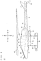
- a helicopter 10 includes a main body 12, a mast 14, a main rotor 16, a tail body 18 and a tail rotor 20.
- the main body 12 includes a main frame 22, a body cover 24, leg portions 26, 28, a pair of skids 30 ( Fig. 1 shows only one skid 30 on the left side), and an under cover 32.
- the tail body 18 and the body cover 24 are supported by the main frame 22.
- Each of the leg portions 26 and 28 has a shape of an inverted letter of U in a front view, and is supported by the main frame 22.
- the pair of skids 30 are positioned side by side to each other, and attached to the leg portions 26 and 28. Specifically, the skid 30 on one side (left side) is attached to one side (left side) of the leg portions 26, 28, whereas the skid 30 (not illustrated) on the other side (right side) is attached to the other side (right side) of the leg portions 26, 28.
- the under cover 32 is attached to the tail body 18 and the main frame 22.
- the mast 14 protrudes upward from the body cover 24, and is rotatable.
- the mast 14 has an upper end portion, where the main rotor 16 is fixed.
- the tail body 18 is substantially cylindrical and extends rearward beyond the main body 12.
- the tail body 18 has a forward end portion, which is supported by a rear end portion of the main frame 22 inside the body cover 24.
- the tail rotor 20 is rotatable, and is at a rearward end portion of the tail body 18.
- the helicopter 10 further includes a display device 34, a drive source 36, a shaft unit 38, a fuel tank 40 and an electric component box 42.
- the shaft unit 38 includes a transmission 44, a drive shaft 46 and a transmittal portion 48, and transmits a driving force from the drive source 36 to the tail rotor 20.
- the fuel tank 40, the drive source 36 and the transmission 44 are housed in the body cover 24.
- the display device 34 is held by the under cover 32.
- the electric component box 42 is inside the main frame 22.
- the drive source 36 is supported by a front end portion of the main frame 22 below the main rotor 16.
- the drive source 36 is provided by an engine. More specifically, the drive source 36 is provided by, for example, a horizontally-opposed multi-cylinder engine.
- the transmission 44 is supported by the main frame 22 behind the drive source 36.
- the transmission 44 is connected to an unillustrated crank shaft of the drive source 36.
- the transmission 44 is connected to a lower end portion of the mast 14.
- the main rotor 16 rotates based on a driving force transmitted from the drive source 36 via the transmission 44 and the mast 14.
- the fuel tank 40 is behind the mast 14.
- the fuel tank 40 has an upper end portion, which is exposed upward from the main body 12.
- the drive shaft 46 extends rearward from the transmission 44.
- the drive shaft 46 extends in a fore-aft direction inside the main body 12 and inside the tail body 18.
- the tail rotor 20 is connected to a rear end portion of the drive shaft 46 via the transmittal portion 48.
- the tail rotor 20 rotates based on a driving force transmitted from the drive source 36 via the transmission 44, the drive shaft 46 and the transmittal portion 48.
- the drive shaft 46 includes a first shaft portion 50a and a second shaft portion 50b. It is desirable that the drive shaft 46 is made of a carbon fiber reinforced plastic. In this case, it becomes possible to achieve a higher specific strength than in cases where the drive shaft 46 is made from other materials.
- the first shaft portion 50a includes a hollow cylindrical shaft main body 52a, and has a mounting portion 54a at an end portion of the shaft main body 52a near the second shaft portion 50b.
- the shaft main body 52a and the mounting portion 54a are integrated with each other by means of adhesion etc. for example.
- the mounting portion 54a is formed into a general shape of letter T, and has a cylindrical portion 56a into which an end portion of the shaft main body 52a is fitted; a generally I-shaped flange portion 58a formed at an end region of the cylindrical portion 56a to extend perpendicularly to an axial direction of the cylindrical portion 56a; and a plurality (two, in the present embodiment) of screw holes 60a, 62a formed at two end regions of the flange portion 58a.
- the flange portion 58a has its two end regions made thicker than its intermediate region.
- the second shaft portion 50b includes a hollow cylindrical shaft main body 52b, and has a mounting portion 54b at an end portion of the shaft main body 52b near the first shaft portion 50a.
- the shaft main body 52b and the mounting portion 54b are integrated with each other by means of adhesion etc. for example.
- the mounting portion 54b is formed into a general shape of letter T, and has a cylindrical portion 56b into which an end portion of the shaft main body 52b is fitted; a generally I-shaped flange portion 58b formed at an end region of the cylindrical portion 56b to extend perpendicularly to an axial direction of the cylindrical portion 56b; and a plurality (two, in the present embodiment) of screw holes 60b, 62b formed at two end regions of the flange portion 58b.
- the flange portion 58b has its two end regions made thicker than its intermediate region.
- the elastic member 64 is provided between the first shaft portion 50a and the second shaft portion 50b.
- the elastic member 64 is, for example, generally quadrangular prismatic.
- the elastic member 64 has, in its intermediate region, a generally quadrangular prismatic through-hole 66 extending in an axial direction of the drive shaft 46; and through-holes 68, 70, 72, 74 extending in the axial direction of the drive shaft 46 around the through-hole 66 at four corners of the elastic member 64.
- the elastic member 64 is made of a rubber material, preferably. The same applies to elastic members 168, 220, 282 which will be described later.
- a strip-like first plate portion 76a is disposed between the first shaft portion 50a and the elastic member 64.
- the first plate portion 76a has a plurality (four, in the present embodiment) of through-holes 78a, 80a, 82a, 84a.
- the through-holes 78a, 84a are formed at locations corresponding to the through-holes 68, 72 of the elastic member 64.
- a strip-like second plate portion 76b is disposed between the second shaft portion 50b and the elastic member 64.
- the second plate portion 76b has a plurality (four, in the present embodiment) of through-holes 78b, 80b, 82b, 84b.
- the through-holes 78b, 84b are formed at locations corresponding to the through-holes 70, 74 of the elastic member 64.
- first shaft portion 50a and the elastic member 64 are connected to each other with the first plate portion 76a in between, whereas the second shaft portion 50b and the elastic member 64 are connected to each other with the second plate portion 76b in between.
- a bolt 86a is inserted from a side of the first shaft portion 50a, through the screw hole 60a of the flange portion 58a, the through-hole 70 of the elastic member 64 and the through-hole 78b of the second plate portion 76b, and is tightened with a nut 90b
- a bolt 88a is inserted through the screw hole 62a of the flange portion 58a, the through-hole 74 of the elastic member 64 and the through-hole 84b of the second plate portion 76b, and is tightened with a nut 92b.
- a bolt 86b is inserted from a side of the second shaft portion 50b, through the screw hole 60b of the flange portion 58b, the through-hole 68 of the elastic member 64 and the through-hole 78a of the first plate portion 76a, and is tightened with a nut 90a
- a bolt 88b is inserted through the screw hole 62b of the flange portion 58b, the through-hole 72 of the elastic member 64 and the through-hole 84a of the second plate portion 76a, and is tightened with a nut 92a.
- the first shaft portion 50a and the elastic member 64 are connected to each other at a plurality (two, in the present embodiment) of locations across a centerline A1 of the drive shaft 46, whereas the second shaft portion 50b and the elastic member 64 are connected to each other at a plurality (two, in the present embodiment) of locations across the centerline A1 of the drive shaft 46.
- the connection location between the first shaft portion 50a and the elastic member 64 is called as a first connection area
- the connection location between the second shaft portion 50b and the elastic member 64 is called as a second connection area
- the first connection areas and the second connection areas do not overlap each other when viewed from the axial direction of the drive shaft 46.
- the first connection areas and the second connection areas are at an angle from each other by approximately 90 degrees in a circumferential direction of the drive shaft 46.
- first plate portion 76a is provided on a main surface on the side of the first shaft portion 50a in the elastic member 64
- the second plate portion 76b is provided on a main surface on the side of the second shaft portion 50b in the elastic member 64.
- first plate portion 76a and the elastic member 64 are connected to each other at a plurality (two, in the present embodiment) of locations across the centerline A1 of the drive shaft 46
- the second plate portion 76b and the elastic member 64 are connected to each other at a plurality (two, in the present embodiment) of locations across the centerline A1 of the drive shaft 46.
- the first shaft portion 50a has a mounting portion 94a at an end region on a side near the transmission 44 of the shaft main body 52a.
- the shaft main body 52a and the mounting portion 94a are integrated with each other by means of adhesion etc. for example.
- the mounting portion 94a is formed into a general shape of letter T, and has a cylindrical portion 96a into which another end portion of the shaft main body 52a is fitted; a generally I-shaped flange portion 98a formed at an end region of the cylindrical portion 96a to extend perpendicularly to an axial direction of the cylindrical portion 96a; and a plurality (two, in the present embodiment) of screw holes 100a, 102a formed at two end regions of the flange portion 98a.
- the flange portion 98a has its two end regions made thicker than its intermediate region.
- the mounting portions 54a and 94a are attached to two end regions of the shaft main body 52a so that two end regions of each flange portion 58a and two end regions of the flange portion 98a do not overlap each other when viewed from the axial direction of the drive shaft 46.
- the mounting portions 54a and 94a are arranged so that a longitudinal direction of the flange portion 58a and a longitudinal direction of the flange portion 98a are at an angle of approximately 90 degrees in a circumferential direction of the drive shaft 46.
- the mounting portion 94a is connected to a mounting portion 94b via a rectangular plate spring 104.
- the mounting portion 94b is formed into a general shape of letter T, and has a cylindrical portion 96b; a generally I-shaped flange portion 98b formed at an end region of the cylindrical portion 96b to extend perpendicularly to an axial direction of the cylindrical portion 96b; and a plurality (two, in the present embodiment) of screw holes 100b, 102b formed at two end regions of the flange portion 98b.
- the flange portion 98b has its two end regions made thicker than its intermediate region.
- the plate spring 104 has through-holes 106, 108, 110, 112 corresponding to the screw holes 100a, 102a, 100b, 102b.
- the plate spring 104 is disposed on an end surface of the flange portion 98a of the mounting portion 94a.
- a bolt 114 is then inserted through the screw hole 100a and the through-hole 106, and is tightened with a nut 116, whereas a bolt 118 is inserted through the screw hole 102a and the through-hole 108, and is tightened with a nut 120.
- the mounting portion 94b is attached to the plate spring 104, and in this process, a bolt 122 is inserted through the through-hole 110 in the plate spring 104, and threaded into the screw hole 100b of the flange portion 98b, whereas a bolt 124 is inserted through the through-hole 112 in the plate spring 104, and threaded into the screw hole 102b of the flange portion 98b. Therefore, the mounting portions 94a and 94b are arranged so that two end regions of the flange portion 98a and two end regions of the flange portion 98b do not overlap each other when viewed from the axial direction of the drive shaft 46.
- the mounting portions 94a and 94b are arranged so that a longitudinal direction of the flange portion 98a and a longitudinal direction of the flange portion 98b are at an angle of approximately 90 degrees in a circumferential direction of the drive shaft 46.
- the second shaft portion 50b has a cylindrical mounting portion 126 attached to a substantially intermediate region of the shaft main body 52b; and a mounting portion 128 attached to an end portion of the shaft main body 52b near the tail rotor 20.
- the mounting portion 128 has a large pipe-portion 130 attached to an end portion of the shaft main body 52b; and a small pipe-portion 132 formed at an end region of the large pipe-portion 130.
- the mounting portions 126 and 128 are integral with the shaft main body 52b by means of adhesion etc. for example.
- the mounting portion 94b is connected to the transmission 44, whereas the mounting portion 128 is connected to the transmittal portion 48.
- a housing 136 is provided via a needle bearing 134.
- the housing 136 is attached to an inner surface of the tail body 18.
- the needle bearing 134 does not have an inner ring, but has a cylindrical outer ring 138, a retainer section 140 on an inner surface of the outer ring 138, and a plurality of rod-like rollers 142 held by the retainer section 140.
- the rollers 142 are circumferentially spaced from each other, extend axially, and are rotatable.
- the cylindrical portion 56b of the mounting portion 54b is surrounded and contacted by the plurality of rollers 142, and is rotatable with respect to the needle bearing 134.
- the housing 136 is annular, and connects the outer ring 138 of the needle bearing 134 and the tail body 18 to each other.
- the housing 136 has axially penetrating through-holes 144, 146, 148, 150.
- a housing 152 is provided in the mounting portion 126 of the drive shaft 46 via a needle bearing (not illustrated).
- the housing 152 is annular, and attached to an inner surface of the tail body 18.
- the housing 152 is smaller in its outer shape than the housing 136, but the housing 152 has the same structure as the housing 136.
- Fig. 10 shows a relationship between a displacement amount of the elastic member 64 and a rotation torque outputted from the elastic member 64. As the displacement amount increases, the rotation torque increases toward a predetermined value in an asymptotic fashion.
- Line A shows a displacement amount vs. rotation torque characteristic when the elastic member has a relatively high hardness: The rotation torque outputted from the elastic member forms an asymptote to a predetermined value Th.
- Line B shows a displacement amount vs. rotation torque characteristic when the elastic member has a relatively low hardness : The rotation torque outputted from the elastic member forms an asymptote to a predetermined value Ts.
- Each of the predetermined values Th and Ts is set to a slightly greater value than values in a normal operation range (of torques required to be transmitted in normal operation). In the normal operation range of torques, both Lines A and B have a substantially linear characteristic.
- the elastic member which has a Line B characteristic is inserted between the first shaft portion 50a and the second shaft portion 50b of the drive shaft 46, and assume that a rotation torque as shown in Fig. 11(a) is inputted from the first shaft portion 50a to the elastic member. Then, as shown in Fig. 11(b) , the elastic member outputs a rotation torque which is smaller than the predetermined value Ts to the second shaft portion 50b. In other words, if the first shaft portion 50a and the second shaft portion 50b are connected to each other without using the elastic member, a rotation torque as shown in Fig. 11(a) is transmitted to the second shaft portion 50b.
- the elastic member which has a Line A characteristic is inserted between the first shaft portion 50a and the second shaft portion 50b of the drive shaft 46, the elastic member outputs a rotation torque which is smaller than the predetermined value Th to the second shaft portion 50b.
- the elastic member 64 is provided in the shaft unit 38 in an interposing fashion. Therefore, even if a high-frequency, high-amplitude variation in the number of rotations occurs and an excessive rotation torque is caused thereby in the shaft unit 38 while the tail rotor 20 is being rotated, the elastic member 64 absorbs the rotation torque. This decreases a rotation torque which occurs in the shaft unit 38. In other words, it is possible to suppress an increase in the rotation torque in the drive shaft 46. Therefore, it is possible to transmit a desired number of rotations and rotation torque from the drive shaft 46 to the tail rotor 20 via the transmittal portion 48 while suppressing development of an excessive rotation torque.
- the drive shaft 46 is supported by the tail body 18 via the needle bearing 134 which does not have an inner ring.
- the needle bearing 134 is not fixed to the drive shaft 46 when disposed around the outer circumference of the drive shaft 46. Therefore, even if there is developed a high-frequency variation in the number of rotations in the drive shaft 46, it is possible to decrease chances for a damage to a contact region between the needle bearing 134 and the drive shaft 46. Also, the drive shaft 46 can be removed/attached easily from the needle bearing 134. This makes it easy to inspect/replace parts.
- the drive shaft 46 is supported by the tail body 18 via the needle bearing 134 and the housing 136. Therefore, it is possible to dispose the needle bearing 134 at an appropriate position for assembling the drive shaft 46 to the needle bearing 134. This makes it possible to assemble the drive shaft 46 easily.
- the housing 136 is provided with the through-holes 144 through 150. This makes it easy to perform maintenance activities to members which are disposed inside the tail body 18, such as replenishing grease to a needle bearing (not illustrated) disposed at a more rearward location than the housing 136.
- the elastic member 64 outputs rotation torques which have values smaller than a predetermined value but does not output rotation torques which have values not smaller than the predetermined value. Therefore, even if an excessive rotation torque which is not smaller than the predetermined value is given from the drive source 36 side, the elastic member 64 does not output the excessive rotation torque to the tail rotor 20 side. Thus, it is possible to suppress increase in the rotation torque and transmit a desired rotation torque to the tail rotor 20.
- the predetermined value of the rotation torque is set to a slightly greater value than values in a normal operation range (of torques required to be transmitted in normal operation), then even if a torque in the normal operation range is a high-frequency torque, it is possible for the elastic member 64 to output the torque which follows it to the tail rotor 20 side.
- the drive shaft 46 has a split construction.
- the first shaft portion 50a and the second shaft portion 50b are connected axially to each other via the elastic member 64. Therefore, it is possible to set an appropriate length to each of the first shaft portion 50a and the second shaft portion 50b to constitute the drive shaft 46. This makes it possible to support the first shaft portion 50a and the second shaft portion 50b appropriately, and to control (rotational/bending) self-excited resonance vibration caused by (twisting/bending) rigidity of the drive shaft 46 which is calculated from the transmitted torque.
- first connection areas connection locations between the first shaft portion 50a and the elastic member 64
- second connection areas connection locations between the second shaft portion 50b and the elastic member 64
- the drive shaft 46 becomes less flexible in a direction of an imaginary plane (within the plane) including the first connection area and the second connection area which overlap each other, and the drive shaft 46.
- the first connection areas and the second connection areas are offset from each other so that the first connection areas and the second connection areas do not overlap each other in a view from the axial direction of the drive shaft 46.
- the drive shaft 46 becomes flexible in any direction, without a tendency that it is stiff in a specific direction. Therefore, even if the drive shaft 46 receives an external force exerted from a direction perpendicular to its axis for example, the drive shaft46 can flex and absorb the external force, and can decrease chances for damage of the drive shaft 46.
- the first plate portion 76a and the second connection areas overlap each other.
- the first plate portion 76a is attached to a different location from the first connection areas (connection locations between the first shaft portion 50a and the elastic member 64).
- the second plate portion 76b and the first connection areas overlap each other.
- the second plate portion 76b is attached to a different location from the second connection areas (connection locations between the second shaft portion 50b and the elastic member 64).
- the present invention is suitably applicable to cases where the drive source 64 includes an engine.
- the drive shaft may include a first shaft portion 154a and a second shaft portion 154b, which are connected to each other via an elastic member 168 (to be described later).
- the first shaft portion 154a includes a hollow cylindrical shaft main body 52a, and has a mounting portion 156a at an end portion of the shaft main body 52a near the second shaft portion 154b.
- the shaft main body 52a and the mounting portion 156a are integrated with each other by means of adhesion etc. for example.
- the mounting portion 156a has a cylindrical portion 158a into which an end portion of the shaft main body 52a is fitted; a generally Y-shaped flange portion 160a formed at an end region of the cylindrical portion 158a to extend in three directions perpendicularly to an axial direction of the cylindrical portion 158a; and a plurality (three, in the present embodiment) of screw holes 162a, 164a, 166a formed at tip regions of the flange portion 160a.
- the flange portion 160a has its tip regions made thicker than its intermediate region.
- the second shaft portion 154b includes a hollow cylindrical shaft main body 52b, and has a mounting portion 156b at an end portion of the shaft main body 52b near the first shaft portion 154a.
- the shaft main body 52b and the mounting portion 156b are integrated with each other by means of adhesion etc. for example.
- the mounting portion 156b has a cylindrical portion 158b into which an end region of the shaft main body 52b is fitted; a generally Y-shaped flange portion 160b formed at an end region of the cylindrical portion 158b to extend in three directions perpendicularly to an axial direction of the cylindrical portion 158b; and a plurality (three, in the present embodiment) of screw holes 162b, 164b, 166b formed at tip regions of the flange portion 160b.
- the flange portion 160b has its tip regions made thicker than its intermediate region.
- An elastic member 168 is provided between the first shaft portion 154a and the second shaft portion 154b.
- the elastic member 168 is, for example, cylindrical.
- the elastic member 168 has, in its intermediate region, a cylindrical through-hole 170 extending in an axial direction of the drive shaft; and a plurality (six, in the present embodiment) of through-holes 172 through 182 extending in an axial direction of the drive shaft around the through-hole 170.
- a generally Y-shaped, platy first plate portion 184a is disposed between the first shaft portion 154a and the elastic member 168.
- the first plate portion 184a has a plurality (three, in the present embodiment) of through-holes 186a, 188a, 190a.
- the through-holes 186a, 188a, 190a are formed at locations corresponding to the through-holes 174, 178, 182 of the elastic member 168.
- a generally Y-shaped, platy second plate portion 184b is disposed between the second shaft portion 154b and the elastic member 168.
- the second plate portion 184b has a plurality (three, in the present embodiment) of through-holes 186b, 188b, 190b.
- the through-holes 186b, 188b, 190b are formed at locations corresponding to the through-holes 172, 176, 180 of the elastic member 168.
- first shaft portion 154a and the elastic member 168 are connected to each other with the first plate portion 184a in between, whereas the second shaft portion 154b and the elastic member 168 are connected to each other with the second plate portion 184b in between.
- a bolt 192a is inserted through the screw hole 162a of the flange portion 160a, the through-hole 172 of the elastic member 168 and the through-hole 186b of the second plate portion 184b, and is tightened with a nut 198b;
- a bolt 194a is inserted through the screw hole 164a of the flange portion 160a, the through-hole 176 of the elastic member 168 and the through-hole 188b of the second plate portion 184b, and is tightened with a nut 200b;
- a bolt 196a is inserted through the screw hole 166a of the flange portion 160a, the through-hole 180 of the elastic member 168 and the through-hole 190b of the second plate portion 184b, and is tightened with a nut 202b.
- a bolt 192b is inserted through the screw hole 162b of the flange portion 160b, the through-hole 174 of the elastic member 168 and the through-hole 186a of the first plate portion 184a, and is tightened with a nut 198a;
- a bolt 194b is inserted through the screw hole 164b of the flange portion 160b, the through-hole 178 of the elastic member 168 and the through-hole 188a of the first plate portion 184a, and is tightened with a nut 200a;
- a bolt 196b is inserted through the screw hole 166b of the flange portion 160a, the through-hole 182 of the elastic member 168 and the through-hole 190a of the first plate portion 184a, and is tightened with a nut 202a.
- the first shaft portion 154a and the elastic member 168 are connected to each other at a plurality (three, in the present embodiment) of locations around a centerline A2 of the drive shaft, whereas the second shaft portion 154b and the elastic member 168 are connected to each other at a plurality (three, in the present embodiment) of locations around the centerline A2 of the drive shaft.
- the connection location between the first shaft portion 154a and the elastic member 168 is called as a first connection area
- the connection location between the second shaft portion 154b and the elastic member 168 is called as a second connection area
- the first connection areas and the second connection areas do not overlap each other when viewed from the axial direction of the drive shaft.
- the first connection areas and the second connection areas are at an angle from each other by approximately 60 degrees in a circumferential direction of the drive shaft.
- the first plate portion 184a is provided on a main surface on the side of the first shaft portion 154a in the elastic member 168
- the second plate portion 184b is provided on a main surface on the side of the second shaft portion 154b in the elastic member 168.
- the first plate portion 184a and the elastic member 168 are connected to each other at a plurality (three, in the present embodiment) of locations around the centerline A2 of the drive shaft
- the second plate portion 184b and the elastic member 168 are connected to each other at a plurality (three, in the present embodiment) of locations around the centerline A2 of the drive shaft.
- the first plate portion 184a and the second connection areas overlap each other
- the second plate portion 184b and the first connection areas overlap each other.
- the embodiment in which the first shaft portion 154a and the second shaft portion 154b are connected as shown in Fig. 12 provides the same advantages as achieved by the embodiment in Fig. 5 , and it is also possible to alter the rotation torque vs. displacement amount characteristic.
- the drive shaft may include a first shaft portion 204a and a second shaft portion 204b, which are connected to each other via an elastic member 220 (which will be described later).
- the first shaft portion 204a includes a hollow cylindrical shaft main body 52a, and has a mounting portion 206a at an end portion of the shaft main body 52a near the second shaft portion 204b.
- the shaft main body 52a and the mounting portion 206a are integrated with each other by means of adhesion etc. for example.
- the mounting portion 206a has a cylindrical portion 208a into which an end portion of the shaft main body 52a is fitted; a generally cross-shaped flange portion 210a formed at an end region of the cylindrical portion 208a to extend in four directions perpendicularly to an axial direction of the cylindrical portion 208a; and a plurality (four, in the present embodiment) of screw holes 212a, 214a, 216a, 218a formed at tip regions of the flange portion 210a.
- the flange portion 210a has its tip regions made thicker than its intermediate region.
- the second shaft portion 204b includes a hollow cylindrical shaft main body 52b, and has a mounting portion 206b at an end portion of the shaft main body 52b near the first shaft portion 204a.
- the shaft main body 52b and the mounting portion 206b are integrated with each other by means of adhesion etc. for example.
- the mounting portion 206b has a cylindrical portion 208b into which an end portion of the shaft main body 52b is fitted; a generally cross-shaped flange portion 210b formed at an end region of the cylindrical portion 208b to extend in four directions perpendicularly to an axial direction of the cylindrical portion 208b; and a plurality (four, in the present embodiment) of screw holes 212b, 214b, 216b, 218b formed at tip regions of the flange portion 210b.
- the flange portion 210b has its tip regions made thicker than its intermediate region.
- the elastic member 220 is provided between the first shaft portion 204a and the second shaft portion 204b.
- the elastic member 220 is, for example, generally octagonal prismatic.
- the elastic member 220 has, in its intermediate region, a generally octagonal prismatic through-hole 222 extending in an axial direction of the drive shaft; and a plurality (eight, in the present embodiment) of through-holes 224 through 238 extending in an axial direction of the drive shaft around the through-hole 222.
- a generally cross-shaped, platy first plate portion 240a is disposed between the first shaft portion 204a and the elastic member 220.
- the first plate portion 240a has a plurality (four, in the present embodiment) of through-holes 242a, 244a, 246a, 248a.
- the through-holes 242a, 244a, 246a, 248a are formed at locations corresponding to the through-holes 226, 230, 234, 238 of the elastic member 220.
- a generally cross-shaped, platy second plate portion 240b is disposed between the second shaft portion 204b and the elastic member 220.
- the second plate portion 240b has a plurality (four, in the present embodiment) of through-holes 242b, 244b, 246b, 248b.
- the through-holes 242b, 244b, 246b, 248b are formed at locations corresponding to the through-holes 224, 228, 232, 236 of the elastic member 220.
- first shaft portion 204a and the elastic member 220 are connected to each other with the first plate portion 240a in between, whereas the second shaft portion 204b and the elastic member 220 are connected to each other with the second plate portion 240b in between.
- a bolt 250a is inserted through the screw hole 212a of the flange portion 210a, the through-hole 224 of the elastic member 220 and the through-hole 242b of the second plate portion 240b, and is tightened with a nut 258b
- a bolt 252a is inserted through the screw hole 214a of the flange portion 210a, the through-hole 228 of the elastic member 220 and the through-hole 244b of the second plate portion 240b, and is tightened with a nut 260b.
- a bolt 254a is inserted through the screw hole 216a of the flange portion 210a, the through-hole 232 of the elastic member 220 and the through-hole 246b of the second plate portion 240b, and is tightened with a nut 262b
- a bolt 256a is inserted through the screw hole 218a of the flange portion 210a, the through-hole 236 of the elastic member 220 and the through-hole 248b of the second plate portion 240b, and is tightened with a nut 264b.
- a bolt 250b is inserted through the screw hole 212b of the flange portion 210b, the through-hole 226 of the elastic member 220 and the through-hole 242a of the first plate portion 240a, and is tightened with a nut 258a
- a bolt 252b is inserted through the screw hole 214b of the flange portion 210b, the through-hole 230 of the elastic member 220 and the through-hole 244a of the first plate portion 240a, and is tightened with a nut 260a.
- a bolt 254b is inserted through the screw hole 216b of the flange portion 210b, the through-hole 234 of the elastic member 220 and the through-hole 246a of the first plate portion 240a, and is tightened with a nut 262a
- a bolt 256b is inserted through the screw hole 218b of the flange portion 210b, the through-hole 238 of the elastic member 220 and the through-hole 248a of the first plate portion 240a, and is tightened with a nut 264a.
- the first shaft portion 204a and the elastic member 220 are connected to each other at a plurality (four, in the present embodiment) of locations around a centerline A3 of the drive shaft, whereas the second shaft portion 204b and the elastic member 220 are connected to each other at a plurality (four, in the present embodiment) of locations around the centerline A3 of the drive shaft.
- the connection location between the first shaft portion 204a and the elastic member 220 is called as a first connection area
- the connection location between the second shaft portion 204b and the elastic member 220 is called as a second connection area
- the first connection areas and the second connection areas do not overlap each other when viewed from the axial direction of the drive shaft.
- the first connection areas and the second connection areas are at an angle from each other by approximately 45 degrees in a circumferential direction of the drive shaft.
- the first plate portion 240a is provided on a main surface on the side of the first shaft portion 204a in the elastic member 220
- the second plate portion 240b is provided on a main surface on the side of the second shaft portion 204b in the elastic member 220.
- the first plate portion 240a and the elastic member 220 are connected to each other at a plurality (four, in the present embodiment) of locations around the centerline A3 of the drive shaft
- the second plate portion 240b and the elastic member 220 are connected to each other at a plurality (four, in the present embodiment) of locations around the centerline A3 of the drive shaft.
- the first plate portion 240a and the second connection areas overlap each other
- the second plate portion 240b and the first connection areas overlap each other.
- first shaft portion 204a and the second shaft portion 204b are connected as shown in Fig. 13 provides the same advantages as achieved by the embodiment in Fig. 5 , and it is also possible to alter the rotation torque vs. displacement amount characteristic.
- the drive shaft may include a first shaft portion 266a and a second shaft portion 266b, which are connected to each other via an elastic member 282 (which will be described later).
- the first shaft portion 266a includes a hollow cylindrical shaft main body 52a, and has a mounting portion 268a at an end portion of the shaft main body 52a near the second shaft portion 266b.
- the shaft main body 52a and the mounting portion 268a are integrated with each other by means of adhesion etc. for example.
- the mounting portion 268a has a cylindrical portion 270a into which an end portion of the shaft main body 52a is fitted; a disc-like flange portion 272a formed at an end region of the cylindrical portion 270a to extend perpendicularly to an axial direction of the cylindrical portion 270a; and a plurality (four, in the present embodiment) of screw holes 274a, 276a, 278a, 280a formed in the flange portion 272a.
- the second shaft portion 266b includes a hollow cylindrical shaft main body 52b, and has a mounting portion 268b at an end portion of the shaft main body 52b near the first shaft portion 266a.
- the shaft main body 52b and the mounting portion 268b are integrated with each other by means of adhesion etc. for example.
- the mounting portion 268b has a cylindrical portion 270b into which an end portion of the shaft main body 52b is fitted; a disc-like flange portion 272b formed at an end region of the cylindrical portion 270b to extend perpendicularly to an axial direction of the cylindrical portion 270b; and a plurality (four, in the present embodiment) of screw holes 274b, 276b, 278b, 280b formed in the flange portion 272b.
- An elastic member 282 is provided between the first shaft portion 266a and the second shaft portion 266b.
- the elastic member 282 is, for example, cylindrical.
- the elastic member 282 has a plurality (four, in the present embodiment) of through-holes 284 through 290 extending in the axial direction of the drive shaft.
- first shaft portion 266a and the second shaft portion 266b are connected to each other with the elastic member 282 in between.
- a bolt 292 is inserted through the screw hole 274a of the flange portion 272a, the through-hole 284 of the elastic member 282 and the screw hole 274b of the flange portion 272b, and is tightened with a nut 300
- a bolt 294 is inserted through the screw hole 276a of the flange portion 272a, the through-hole 286 of the elastic member 282 and the screw hole 276b of the flange portion 272b, and is tightened with a nut 302.
- a bolt 296 is inserted through the screw hole 278a of the flange portion 272a, the through-hole 288 of the elastic member 282 and the screw hole 278b of the flange portion 272b, and is tightened with a nut 304
- a bolt 298 is inserted through the screw hole 280a of the flange portion 272a, the through-hole 290 of the elastic member 282 and the screw hole 280b of the flange portion 272b, and is tightened with a nut 306.
- first shaft portion 266a and the elastic member 282 are connected to each other at a plurality (four, in the present embodiment) of locations around a centerline A4 of the drive shaft, whereas the second shaft portion 266b and the elastic member 282 are connected to each other at a plurality (four, in the present embodiment) of locations around the centerline A4 of the drive shaft.
- first shaft portion 266a and the second shaft portion 266b are connected as shown in Fig. 14 provides the same advantages as achieved by the embodiment in Fig. 5 , and it is also possible to alter the rotation torque vs. displacement amount characteristic.
- the elastic member may be inserted anywhere in the shaft unit between a location between the transmission and the drive shaft and a location between the drive shaft and the transmittal portion.
- the shape of the elastic member is not limited to those described above, and any appropriate shape may be selected in accordance with characteristics of the drive source, a desired number of rotations of the tail rotor, desired rotation torques, a desired normal torque range, etc.
- an equilateral prismatic body which has an even number of side surfaces in particular, is preferable.
- the bearing is not limited to a needle bearing. Any bearing which does not have an inner ring and is attached around an outer circumference of the drive shaft to make direct contact with the drive shaft may be used.
Landscapes
- Engineering & Computer Science (AREA)
- Aviation & Aerospace Engineering (AREA)
- Mechanical Engineering (AREA)
- Chemical & Material Sciences (AREA)
- Combustion & Propulsion (AREA)
- Sustainable Development (AREA)
- Sustainable Energy (AREA)
- Life Sciences & Earth Sciences (AREA)
- Remote Sensing (AREA)
- Vibration Prevention Devices (AREA)
- Toys (AREA)
- Transmission Devices (AREA)
- Electrophotography Configuration And Component (AREA)
- Shafts, Cranks, Connecting Bars, And Related Bearings (AREA)
Abstract
Description
- The present invention relates to unmanned helicopters and more specifically to an unmanned helicopter including a drive shaft.
- An example of conventional techniques in this kind is disclosed in Patent Literature 1. Patent Literature 1 discloses an unmanned helicopter including a transmission shaft (drive shaft) which transmits a rotation torque to a tail rotor; a tail boom which supports the transmission shaft; and a cosmetic cover which covers an outer circumferential surface of the tail boom. In this arrangement, an elastic member is placed between the outer circumferential surface of the tail boom and the cosmetic cover which opposes thereto.
- Such an unmanned helicopter as the above requires exact control on the number of rotations of the tail rotor for the helicopter's attitude control. In order to achieve this, a desired rotation torque must be transmitted to the tail rotor via the tail boom.
- PATENT LITERATURE 1:
JP-Y H6-6876 - However, in the unmanned helicopter disclosed in Patent Literature 1, there can be a problem that if a high-frequency, high-amplitude variation in the number of rotations is caused in the transmission shaft by a hunting phenomenon from an engine rotational variation or the like when the tail rotor is rotated, a large rotation torque will result in the transmission shaft due to the variation in the number of rotations.
- Therefore, a primary object of the present invention is to provide an unmanned helicopter capable of suppressing increase in the rotation torque in the drive shaft and transmitting a desired number of rotations and rotation torque to the tail rotor even if a shaft unit comes under a high-frequency, high-amplitude variation in the number of rotations when the tail rotor is rotated.
- According to an aspect of the present invention, there is provided an unmanned helicopter which includes a drive source; a tail rotor; a shaft unit for transmitting a driving force from the drive source to the tail rotor; and an elastic member disposed in the shaft unit. In this helicopter, the shaft unit includes a drive shaft, a transmission which transmits a driving force from the drive source to the drive shaft, and a transmittal portion for transmitting a rotation torque from the drive shaft to the tail rotor. Further, the elastic member is interposed in the shaft unit between a location between the transmission and the drive shaft and a location between the drive shaft and the transmittal portion.
- According to the present invention, the elastic member is provided in the shaft unit in an interposing fashion. Therefore, even if a high-frequency, high-amplitude variation in the number of rotations occurs and an excessive rotation torque is caused thereby in the shaft unit while the tail rotor is being rotated, the elastic member absorbs the rotation torque. This decreases the rotation torque which occurs in the shaft unit. In other words, it is possible to suppress an increase in the rotation torque in the drive shaft. Therefore, it is possible to transmit a desired number of rotations and rotation torque from the drive shaft to the tail rotor via the transmittal portion while suppressing development of an excessive rotation torque.
- Preferably, the unmanned helicopter further includes a bearing which does not have an inner ring and is disposed around an outer circumference of the drive shaft in direct contact with the drive shaft; and a tail body which covers the drive shaft and supports the drive shaft via the bearing. In this case, the drive shaft is supported by the tail body via a bearing which does not have an inner ring, such as a needle bearing for example. When attached to an outer circumference of the drive shaft, the bearing is not fixed onto the drive shaft. Therefore, even if there is developed a high-frequency variation in the number of rotations in the drive shaft, it is possible to decrease chances for a damage to a contact region between the bearing and the drive shaft. Also, the drive shaft can be removed/attached easily from the bearing. This makes it easy to inspect/replace parts.
- Further preferably, the unmanned helicopter further includes a housing provided around an outer circumference of the bearing and supported by the tail body. The housing includes a hole penetrating in an axial direction of the drive shaft. In this case, the drive shaft is supported by the tail body via the bearing and the housing. Therefore, it is possible to dispose the bearing at an appropriate position for assembling the drive shaft to the bearing. This makes it possible to assemble the drive shaft easily. Also, the hole in the housing makes it easy to provide maintenance to members disposed inside the tail body.
- Further, preferably, the elastic member has a relationship between a displacement amount of the elastic member and a rotation torque outputted from the elastic member that as the displacement amount increases, the rotation torque increases toward a predetermined value in an asymptotic fashion. In this case, the elastic member outputs rotation torques which have values lower than a predetermined value but does not output rotation torques which have values higher than the predetermined value. Therefore, even if an excessive rotation torque which is not smaller than the predetermined value is given from the drive source side, the elastic member does not output the excessive rotation torque to the tail rotor side. Thus, it is possible to suppress increase in the rotation torque and transmit a desired rotation torque to the tail rotor. Also, if the predetermined value of the rotation torque is set to a slightly greater value than values in a normal operation range (of torques required to be transmitted in normal operation), then even if a torque in the normal operation range is a high-frequency torque, it is possible for the elastic member to output the torque which follows it to the tail rotor side.
- Preferably, the drive shaft includes a first shaft portion and a second shaft portion, and the elastic member is between the first shaft portion and the second shaft portion. In this case, the drive shaft has a split construction. The first shaft portion and the second shaft portion are connected axially to each other via the elastic member. Therefore, it is possible to set an appropriate length to each of the first shaft portion and the second shaft portion to constitute the drive shaft. This makes it possible to support each shaft portion appropriately, and to control (rotational/bending) self-excited resonance vibration caused by (twisting/bending) rigidity of the drive shaft which is calculated from the transmitted torque.
- Further preferably, the first shaft portion and the elastic member are connected to each other at a plurality of locations across or around a centerline of the drive shaft, whereas the second shaft portion and the elastic member are connected to each other at a plurality of locations across or around the centerline of the drive shaft, under the following relationship where, the connection location between the first shaft portion and the elastic member is called as a first connection area, and the connection location between the second shaft portion and the elastic member is called as a second connection area, then the first connection areas and the second connection areas do not overlap each other when viewed from an axial direction of the drive shaft. If the first connection areas and the second connection areas overlap each other when viewed from the axial direction of the drive shaft, then the drive shaft is less flexible in a direction of an imaginary plane (within the plane) including the first connection area and the second connection area which overlap each other, and the drive shaft. To avoid this, as described above, the first connection areas and the second connection areas are offset from each other so that the first connection areas and the second connection areas do not overlap each other in a view from the axial direction of the drive shaft. By doing so, the drive shaft becomes flexible in any direction, without a tendency that it is stiff in a specific direction. Therefore, even if the drive shaft receives an external force exerted from a direction perpendicular to its axis for example, the drive shaft can flex and absorb the external force, and can decrease chances for damage of the drive shaft.
- Further, preferably, the unmanned helicopter further includes a first plate portion provided on a main surface of the elastic member which faces the first shaft portion; and a second plate portion provided on a main surface of the elastic member which faces the second shaft portion. With the above arrangement, the first plate portion and the elastic member are connected to each other at a plurality of locations across or around the centerline of the drive shaft. Further, the second plate portion and the elastic member are connected to each other at a plurality of locations across or around the centerline of the drive shaft. The first plate portion and the second connection areas overlap each other, and the second plate portion and the first connection areas overlap each other in a view from the axial direction of the drive shaft. In this case, when viewed from the axial direction of the drive shaft, the first plate portion and the second connection areas overlap each other. In the main surface of the elastic member which faces the first shaft portion, the first plate portion is attached to a different location from the first connection areas. Also, when viewed from the axial direction of the drive shaft, the second plate portion and the first connection areas overlap each other. In the main surface of the elastic member which faces the second shaft portion, the second plate portion is attached to a different location from the second connection areas. By attaching the first plate portion and the second plate portion to the elastic member as described, it becomes possible to suppress undesirable distortion of the elastic member.
- Preferably, the drive source includes an engine. In cases where the drive source is provided by an engine, there is a higher tendency that a high-frequency vibration is developed by variation in the number of engine rotations for example, in the shaft unit. Therefore, the present invention is suitably applicable to cases where the drive source includes an engine.
- The above-described object and other objects, characteristics, aspects and advantages of the present invention will become clearer from the following detailed description of embodiments of the present invention to be made with reference to the attached drawings.
-
-
Fig. 1 is a side view showing an unmanned helicopter according to an embodiment of the present invention. -
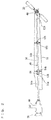
Fig. 2 is an illustrative side view of a shaft unit taken from a side (left side). -
Fig. 3 is an illustrative plan view of the shaft unit taken from above. -
Fig. 4 is a perspective view showing a drive shaft with an elastic member interposed therein. -
Fig. 5 is an exploded perspective view showing a vicinity of connection areas between the drive shaft and the elastic member. -
Fig. 6 is a perspective view showing two end regions of a first shaft portion. -
Fig. 7(a) is a plan view showing the two end regions of the first shaft portion, whereasFig. 7(b) is a side view thereof. -
Fig. 8 is a perspective view showing a primary portion of a needle bearing attached to the drive shaft and a housing. -
Fig. 9 is a perspective view showing a primary portion of the needle bearing and the housing. -
Fig. 10 is a graph showing a displacement amount vs. rotation torque characteristic of the elastic member. -
Fig. 11 (a) is an illustrative drawing of an input rotation torque to the elastic member, whereasFig. 11(b) is an illustrative drawing of an output rotation torque from the elastic member. -
Fig. 12 is an exploded perspective view showing a vicinity of connection areas between a drive shaft and an elastic member as another example. -
Fig. 13 is an exploded perspective view showing a vicinity of connection areas between a drive shaft and an elastic member as still another example. -
Fig. 14 is an exploded perspective view showing a vicinity of connection areas between a drive shaft and an elastic member as still another example. - Hereinafter, embodiments of the present invention will be described with reference to the drawings. It is noted that the terms front and rear, left and right, up and down used in the embodiments are determined from a basic attitude (which is an attitude of the
helicopter 10 when itsmast 14 is parallel to the vertical direction) of an unmanned helicopter 10 (hereinafter simply termed as helicopter 10). InFig. 1 , "Fr" means forward, "Rr" means rearward, "U" means upward and "Lo" means downward. - Referring to
Fig. 1 , ahelicopter 10 includes amain body 12, amast 14, amain rotor 16, atail body 18 and atail rotor 20. - The
main body 12 includes amain frame 22, abody cover 24,leg portions Fig. 1 shows only oneskid 30 on the left side), and an undercover 32. - The
tail body 18 and thebody cover 24 are supported by themain frame 22. - Each of the
leg portions main frame 22. - The pair of
skids 30 are positioned side by side to each other, and attached to theleg portions skid 30 on one side (left side) is attached to one side (left side) of theleg portions leg portions - The under
cover 32 is attached to thetail body 18 and themain frame 22. - The
mast 14 protrudes upward from thebody cover 24, and is rotatable. Themast 14 has an upper end portion, where themain rotor 16 is fixed. Thus, themast 14 and themain rotor 16 rotate integrally with each other. Thetail body 18 is substantially cylindrical and extends rearward beyond themain body 12. Thetail body 18 has a forward end portion, which is supported by a rear end portion of themain frame 22 inside thebody cover 24. Thetail rotor 20 is rotatable, and is at a rearward end portion of thetail body 18. - The
helicopter 10 further includes adisplay device 34, adrive source 36, ashaft unit 38, afuel tank 40 and anelectric component box 42. Referring also toFig. 2 andFig. 3 , theshaft unit 38 includes atransmission 44, adrive shaft 46 and atransmittal portion 48, and transmits a driving force from thedrive source 36 to thetail rotor 20. - The
fuel tank 40, thedrive source 36 and thetransmission 44 are housed in thebody cover 24. Thedisplay device 34 is held by theunder cover 32. Theelectric component box 42 is inside themain frame 22. - The
drive source 36 is supported by a front end portion of themain frame 22 below themain rotor 16. In the present embodiment, thedrive source 36 is provided by an engine. More specifically, thedrive source 36 is provided by, for example, a horizontally-opposed multi-cylinder engine. - The
transmission 44 is supported by themain frame 22 behind thedrive source 36. Thetransmission 44 is connected to an unillustrated crank shaft of thedrive source 36. Thetransmission 44 is connected to a lower end portion of themast 14. Themain rotor 16 rotates based on a driving force transmitted from thedrive source 36 via thetransmission 44 and themast 14. Thefuel tank 40 is behind themast 14. Thefuel tank 40 has an upper end portion, which is exposed upward from themain body 12. - The
drive shaft 46 extends rearward from thetransmission 44. Thedrive shaft 46 extends in a fore-aft direction inside themain body 12 and inside thetail body 18. Thetail rotor 20 is connected to a rear end portion of thedrive shaft 46 via thetransmittal portion 48. Thetail rotor 20 rotates based on a driving force transmitted from thedrive source 36 via thetransmission 44, thedrive shaft 46 and thetransmittal portion 48. - Referring to
Fig. 4 , thedrive shaft 46 includes afirst shaft portion 50a and asecond shaft portion 50b. It is desirable that thedrive shaft 46 is made of a carbon fiber reinforced plastic. In this case, it becomes possible to achieve a higher specific strength than in cases where thedrive shaft 46 is made from other materials. - Referring also to
Fig. 5 , thefirst shaft portion 50a includes a hollow cylindrical shaftmain body 52a, and has a mountingportion 54a at an end portion of the shaftmain body 52a near thesecond shaft portion 50b. The shaftmain body 52a and the mountingportion 54a are integrated with each other by means of adhesion etc. for example. The mountingportion 54a is formed into a general shape of letter T, and has acylindrical portion 56a into which an end portion of the shaftmain body 52a is fitted; a generally I-shapedflange portion 58a formed at an end region of thecylindrical portion 56a to extend perpendicularly to an axial direction of thecylindrical portion 56a; and a plurality (two, in the present embodiment) ofscrew holes flange portion 58a. Theflange portion 58a has its two end regions made thicker than its intermediate region. - Likewise, the
second shaft portion 50b includes a hollow cylindrical shaftmain body 52b, and has a mountingportion 54b at an end portion of the shaftmain body 52b near thefirst shaft portion 50a. The shaftmain body 52b and the mountingportion 54b are integrated with each other by means of adhesion etc. for example. The mountingportion 54b is formed into a general shape of letter T, and has acylindrical portion 56b into which an end portion of the shaftmain body 52b is fitted; a generally I-shapedflange portion 58b formed at an end region of thecylindrical portion 56b to extend perpendicularly to an axial direction of thecylindrical portion 56b; and a plurality (two, in the present embodiment) ofscrew holes flange portion 58b. Theflange portion 58b has its two end regions made thicker than its intermediate region. - An
elastic member 64 is provided between thefirst shaft portion 50a and thesecond shaft portion 50b. Theelastic member 64 is, for example, generally quadrangular prismatic. Theelastic member 64 has, in its intermediate region, a generally quadrangular prismatic through-hole 66 extending in an axial direction of thedrive shaft 46; and through-holes drive shaft 46 around the through-hole 66 at four corners of theelastic member 64. Theelastic member 64 is made of a rubber material, preferably. The same applies toelastic members - A strip-like
first plate portion 76a is disposed between thefirst shaft portion 50a and theelastic member 64. Thefirst plate portion 76a has a plurality (four, in the present embodiment) of through-holes holes holes elastic member 64. Likewise, a strip-likesecond plate portion 76b is disposed between thesecond shaft portion 50b and theelastic member 64. Thesecond plate portion 76b has a plurality (four, in the present embodiment) of through-holes holes 78b, 84b are formed at locations corresponding to the through-holes elastic member 64. - With the above, the
first shaft portion 50a and theelastic member 64 are connected to each other with thefirst plate portion 76a in between, whereas thesecond shaft portion 50b and theelastic member 64 are connected to each other with thesecond plate portion 76b in between. In this process, abolt 86a is inserted from a side of thefirst shaft portion 50a, through thescrew hole 60a of theflange portion 58a, the through-hole 70 of theelastic member 64 and the through-hole 78b of thesecond plate portion 76b, and is tightened with anut 90b, whereas abolt 88a is inserted through thescrew hole 62a of theflange portion 58a, the through-hole 74 of theelastic member 64 and the through-hole 84b of thesecond plate portion 76b, and is tightened with anut 92b. Likewise, abolt 86b is inserted from a side of thesecond shaft portion 50b, through thescrew hole 60b of theflange portion 58b, the through-hole 68 of theelastic member 64 and the through-hole 78a of thefirst plate portion 76a, and is tightened with anut 90a, whereas abolt 88b is inserted through thescrew hole 62b of theflange portion 58b, the through-hole 72 of theelastic member 64 and the through-hole 84a of thesecond plate portion 76a, and is tightened with anut 92a. - As described above, the
first shaft portion 50a and theelastic member 64 are connected to each other at a plurality (two, in the present embodiment) of locations across a centerline A1 of thedrive shaft 46, whereas thesecond shaft portion 50b and theelastic member 64 are connected to each other at a plurality (two, in the present embodiment) of locations across the centerline A1 of thedrive shaft 46. Where, the connection location between thefirst shaft portion 50a and theelastic member 64 is called as a first connection area, whereas the connection location between thesecond shaft portion 50b and theelastic member 64 is called as a second connection area, then the first connection areas and the second connection areas do not overlap each other when viewed from the axial direction of thedrive shaft 46. Specifically, the first connection areas and the second connection areas are at an angle from each other by approximately 90 degrees in a circumferential direction of thedrive shaft 46. - Also, the
first plate portion 76a is provided on a main surface on the side of thefirst shaft portion 50a in theelastic member 64, whereas thesecond plate portion 76b is provided on a main surface on the side of thesecond shaft portion 50b in theelastic member 64. Further, thefirst plate portion 76a and theelastic member 64 are connected to each other at a plurality (two, in the present embodiment) of locations across the centerline A1 of thedrive shaft 46, whereas thesecond plate portion 76b and theelastic member 64 are connected to each other at a plurality (two, in the present embodiment) of locations across the centerline A1 of thedrive shaft 46. When viewed from the axial direction of thedrive shaft 46, thefirst plate portion 76a and the second connection areas overlap each other, whereas thesecond plate portion 76b and the first connection areas overlap each other. - Referring to
Fig. 6 andFig. 7 , thefirst shaft portion 50a has a mountingportion 94a at an end region on a side near thetransmission 44 of the shaftmain body 52a. The shaftmain body 52a and the mountingportion 94a are integrated with each other by means of adhesion etc. for example. The mountingportion 94a is formed into a general shape of letter T, and has acylindrical portion 96a into which another end portion of the shaftmain body 52a is fitted; a generally I-shapedflange portion 98a formed at an end region of thecylindrical portion 96a to extend perpendicularly to an axial direction of thecylindrical portion 96a; and a plurality (two, in the present embodiment) ofscrew holes flange portion 98a. Theflange portion 98a has its two end regions made thicker than its intermediate region. The mountingportions main body 52a so that two end regions of eachflange portion 58a and two end regions of theflange portion 98a do not overlap each other when viewed from the axial direction of thedrive shaft 46. Specifically, the mountingportions flange portion 58a and a longitudinal direction of theflange portion 98a are at an angle of approximately 90 degrees in a circumferential direction of thedrive shaft 46. - The mounting
portion 94a is connected to a mountingportion 94b via arectangular plate spring 104. The mountingportion 94b is formed into a general shape of letter T, and has acylindrical portion 96b; a generally I-shapedflange portion 98b formed at an end region of thecylindrical portion 96b to extend perpendicularly to an axial direction of thecylindrical portion 96b; and a plurality (two, in the present embodiment) ofscrew holes flange portion 98b. Theflange portion 98b has its two end regions made thicker than its intermediate region. Theplate spring 104 has through-holes screw holes - The
plate spring 104 is disposed on an end surface of theflange portion 98a of the mountingportion 94a. Abolt 114 is then inserted through thescrew hole 100a and the through-hole 106, and is tightened with anut 116, whereas abolt 118 is inserted through thescrew hole 102a and the through-hole 108, and is tightened with anut 120. Under this state, the mountingportion 94b is attached to theplate spring 104, and in this process, abolt 122 is inserted through the through-hole 110 in theplate spring 104, and threaded into thescrew hole 100b of theflange portion 98b, whereas abolt 124 is inserted through the through-hole 112 in theplate spring 104, and threaded into thescrew hole 102b of theflange portion 98b. Therefore, the mountingportions flange portion 98a and two end regions of theflange portion 98b do not overlap each other when viewed from the axial direction of thedrive shaft 46. Specifically, the mountingportions flange portion 98a and a longitudinal direction of theflange portion 98b are at an angle of approximately 90 degrees in a circumferential direction of thedrive shaft 46. - Returning to
Fig. 4 , thesecond shaft portion 50b has a cylindrical mountingportion 126 attached to a substantially intermediate region of the shaftmain body 52b; and a mountingportion 128 attached to an end portion of the shaftmain body 52b near thetail rotor 20. The mountingportion 128 has a large pipe-portion 130 attached to an end portion of the shaftmain body 52b; and a small pipe-portion 132 formed at an end region of the large pipe-portion 130. The mountingportions main body 52b by means of adhesion etc. for example. - Referring also to
Fig. 2 andFig. 3 , in thedrive shaft 46 as the above, the mountingportion 94b is connected to thetransmission 44, whereas the mountingportion 128 is connected to thetransmittal portion 48. - Further, referring to
Fig. 8 andFig. 9 , at thecylindrical portion 56b of the mountingportion 54b, ahousing 136 is provided via aneedle bearing 134. Thehousing 136 is attached to an inner surface of thetail body 18. Theneedle bearing 134 does not have an inner ring, but has a cylindricalouter ring 138, aretainer section 140 on an inner surface of theouter ring 138, and a plurality of rod-like rollers 142 held by theretainer section 140. Therollers 142 are circumferentially spaced from each other, extend axially, and are rotatable. Thecylindrical portion 56b of the mountingportion 54b is surrounded and contacted by the plurality ofrollers 142, and is rotatable with respect to theneedle bearing 134. Thehousing 136 is annular, and connects theouter ring 138 of theneedle bearing 134 and thetail body 18 to each other. Thehousing 136 has axially penetrating through-holes - Returning to
Fig. 2 andFig. 3 , ahousing 152 is provided in the mountingportion 126 of thedrive shaft 46 via a needle bearing (not illustrated). Thehousing 152 is annular, and attached to an inner surface of thetail body 18. Thehousing 152 is smaller in its outer shape than thehousing 136, but thehousing 152 has the same structure as thehousing 136. - Next, the
elastic member 64 will be described. -
Fig. 10 shows a relationship between a displacement amount of theelastic member 64 and a rotation torque outputted from theelastic member 64. As the displacement amount increases, the rotation torque increases toward a predetermined value in an asymptotic fashion. - In
Fig. 10 , Line A shows a displacement amount vs. rotation torque characteristic when the elastic member has a relatively high hardness: The rotation torque outputted from the elastic member forms an asymptote to a predetermined value Th. Line B shows a displacement amount vs. rotation torque characteristic when the elastic member has a relatively low hardness : The rotation torque outputted from the elastic member forms an asymptote to a predetermined value Ts. Each of the predetermined values Th and Ts is set to a slightly greater value than values in a normal operation range (of torques required to be transmitted in normal operation). In the normal operation range of torques, both Lines A and B have a substantially linear characteristic. - For example, assume that the elastic member which has a Line B characteristic is inserted between the
first shaft portion 50a and thesecond shaft portion 50b of thedrive shaft 46, and assume that a rotation torque as shown inFig. 11(a) is inputted from thefirst shaft portion 50a to the elastic member. Then, as shown inFig. 11(b) , the elastic member outputs a rotation torque which is smaller than the predetermined value Ts to thesecond shaft portion 50b. In other words, if thefirst shaft portion 50a and thesecond shaft portion 50b are connected to each other without using the elastic member, a rotation torque as shown inFig. 11(a) is transmitted to thesecond shaft portion 50b. - Likewise, if the elastic member which has a Line A characteristic is inserted between the
first shaft portion 50a and thesecond shaft portion 50b of thedrive shaft 46, the elastic member outputs a rotation torque which is smaller than the predetermined value Th to thesecond shaft portion 50b. - According to the
helicopter 10 as described, theelastic member 64 is provided in theshaft unit 38 in an interposing fashion. Therefore, even if a high-frequency, high-amplitude variation in the number of rotations occurs and an excessive rotation torque is caused thereby in theshaft unit 38 while thetail rotor 20 is being rotated, theelastic member 64 absorbs the rotation torque. This decreases a rotation torque which occurs in theshaft unit 38. In other words, it is possible to suppress an increase in the rotation torque in thedrive shaft 46. Therefore, it is possible to transmit a desired number of rotations and rotation torque from thedrive shaft 46 to thetail rotor 20 via thetransmittal portion 48 while suppressing development of an excessive rotation torque. - The
drive shaft 46 is supported by thetail body 18 via theneedle bearing 134 which does not have an inner ring. Theneedle bearing 134 is not fixed to thedrive shaft 46 when disposed around the outer circumference of thedrive shaft 46. Therefore, even if there is developed a high-frequency variation in the number of rotations in thedrive shaft 46, it is possible to decrease chances for a damage to a contact region between theneedle bearing 134 and thedrive shaft 46. Also, thedrive shaft 46 can be removed/attached easily from theneedle bearing 134. This makes it easy to inspect/replace parts. - The
drive shaft 46 is supported by thetail body 18 via theneedle bearing 134 and thehousing 136. Therefore, it is possible to dispose theneedle bearing 134 at an appropriate position for assembling thedrive shaft 46 to theneedle bearing 134. This makes it possible to assemble thedrive shaft 46 easily. Also, thehousing 136 is provided with the through-holes 144 through 150. This makes it easy to perform maintenance activities to members which are disposed inside thetail body 18, such as replenishing grease to a needle bearing (not illustrated) disposed at a more rearward location than thehousing 136. - The
elastic member 64 outputs rotation torques which have values smaller than a predetermined value but does not output rotation torques which have values not smaller than the predetermined value. Therefore, even if an excessive rotation torque which is not smaller than the predetermined value is given from thedrive source 36 side, theelastic member 64 does not output the excessive rotation torque to thetail rotor 20 side. Thus, it is possible to suppress increase in the rotation torque and transmit a desired rotation torque to thetail rotor 20. Also, if the predetermined value of the rotation torque is set to a slightly greater value than values in a normal operation range (of torques required to be transmitted in normal operation), then even if a torque in the normal operation range is a high-frequency torque, it is possible for theelastic member 64 to output the torque which follows it to thetail rotor 20 side. - The
drive shaft 46 has a split construction. Thefirst shaft portion 50a and thesecond shaft portion 50b are connected axially to each other via theelastic member 64. Therefore, it is possible to set an appropriate length to each of thefirst shaft portion 50a and thesecond shaft portion 50b to constitute thedrive shaft 46. This makes it possible to support thefirst shaft portion 50a and thesecond shaft portion 50b appropriately, and to control (rotational/bending) self-excited resonance vibration caused by (twisting/bending) rigidity of thedrive shaft 46 which is calculated from the transmitted torque. - If the first connection areas (connection locations between the
first shaft portion 50a and the elastic member 64) and the second connection areas (connection locations between thesecond shaft portion 50b and the elastic member 64) overlap each other when viewed from the axial direction of thedrive shaft 46, then thedrive shaft 46 becomes less flexible in a direction of an imaginary plane (within the plane) including the first connection area and the second connection area which overlap each other, and thedrive shaft 46. To avoid this, the first connection areas and the second connection areas are offset from each other so that the first connection areas and the second connection areas do not overlap each other in a view from the axial direction of thedrive shaft 46. By doing so, thedrive shaft 46 becomes flexible in any direction, without a tendency that it is stiff in a specific direction. Therefore, even if thedrive shaft 46 receives an external force exerted from a direction perpendicular to its axis for example, the drive shaft46 can flex and absorb the external force, and can decrease chances for damage of thedrive shaft 46. - When viewed from the axial direction of the
drive shaft 46, thefirst plate portion 76a and the second connection areas (connection locations between thesecond shaft portion 50b and the elastic member 64) overlap each other. In a main surface of theelastic member 64 which faces thefirst shaft portion 50a, thefirst plate portion 76a is attached to a different location from the first connection areas (connection locations between thefirst shaft portion 50a and the elastic member 64). Also, when viewed from the axial direction of thedrive shaft 46, thesecond plate portion 76b and the first connection areas (connection locations between thefirst shaft portion 50a and the elastic member 64) overlap each other. In a main surface of theelastic member 64 which faces thesecond shaft portion 50b, thesecond plate portion 76b is attached to a different location from the second connection areas (connection locations between thesecond shaft portion 50b and the elastic member 64). By attaching thefirst plate portion 76a and thesecond plate portion 76b to theelastic member 64 as described, it becomes possible to suppress undesirable distortion of theelastic member 64. - In cases where the
drive source 64 is provided by an engine, there is a higher tendency that high-frequency vibration is developed by the variation in the number of engine rotations for example, in theshaft unit 38. Therefore, the present invention is suitably applicable to cases where thedrive source 64 includes an engine. - Referring to
Fig. 12 , the drive shaft may include afirst shaft portion 154a and asecond shaft portion 154b, which are connected to each other via an elastic member 168 (to be described later). - The
first shaft portion 154a includes a hollow cylindrical shaftmain body 52a, and has a mountingportion 156a at an end portion of the shaftmain body 52a near thesecond shaft portion 154b. The shaftmain body 52a and the mountingportion 156a are integrated with each other by means of adhesion etc. for example. The mountingportion 156a has acylindrical portion 158a into which an end portion of the shaftmain body 52a is fitted; a generally Y-shapedflange portion 160a formed at an end region of thecylindrical portion 158a to extend in three directions perpendicularly to an axial direction of thecylindrical portion 158a; and a plurality (three, in the present embodiment) ofscrew holes flange portion 160a. Theflange portion 160a has its tip regions made thicker than its intermediate region. - Likewise, the
second shaft portion 154b includes a hollow cylindrical shaftmain body 52b, and has a mountingportion 156b at an end portion of the shaftmain body 52b near thefirst shaft portion 154a. The shaftmain body 52b and the mountingportion 156b are integrated with each other by means of adhesion etc. for example. The mountingportion 156b has acylindrical portion 158b into which an end region of the shaftmain body 52b is fitted; a generally Y-shapedflange portion 160b formed at an end region of thecylindrical portion 158b to extend in three directions perpendicularly to an axial direction of thecylindrical portion 158b; and a plurality (three, in the present embodiment) ofscrew holes flange portion 160b. Theflange portion 160b has its tip regions made thicker than its intermediate region. - An
elastic member 168 is provided between thefirst shaft portion 154a and thesecond shaft portion 154b. Theelastic member 168 is, for example, cylindrical. Theelastic member 168 has, in its intermediate region, a cylindrical through-hole 170 extending in an axial direction of the drive shaft; and a plurality (six, in the present embodiment) of through-holes 172 through 182 extending in an axial direction of the drive shaft around the through-hole 170. - A generally Y-shaped, platy
first plate portion 184a is disposed between thefirst shaft portion 154a and theelastic member 168. Thefirst plate portion 184a has a plurality (three, in the present embodiment) of through-holes holes holes elastic member 168. Likewise, a generally Y-shaped, platysecond plate portion 184b is disposed between thesecond shaft portion 154b and theelastic member 168. Thesecond plate portion 184b has a plurality (three, in the present embodiment) of through-holes holes holes elastic member 168. - With the above, the
first shaft portion 154a and theelastic member 168 are connected to each other with thefirst plate portion 184a in between, whereas thesecond shaft portion 154b and theelastic member 168 are connected to each other with thesecond plate portion 184b in between. In this process, from a side of thefirst shaft portion 154a, abolt 192a is inserted through thescrew hole 162a of theflange portion 160a, the through-hole 172 of theelastic member 168 and the through-hole 186b of thesecond plate portion 184b, and is tightened with anut 198b; abolt 194a is inserted through thescrew hole 164a of theflange portion 160a, the through-hole 176 of theelastic member 168 and the through-hole 188b of thesecond plate portion 184b, and is tightened with anut 200b; and abolt 196a is inserted through thescrew hole 166a of theflange portion 160a, the through-hole 180 of theelastic member 168 and the through-hole 190b of thesecond plate portion 184b, and is tightened with anut 202b. Likewise, from a side of thesecond shaft portion 154b, abolt 192b is inserted through thescrew hole 162b of theflange portion 160b, the through-hole 174 of theelastic member 168 and the through-hole 186a of thefirst plate portion 184a, and is tightened with anut 198a; abolt 194b is inserted through thescrew hole 164b of theflange portion 160b, the through-hole 178 of theelastic member 168 and the through-hole 188a of thefirst plate portion 184a, and is tightened with anut 200a; and abolt 196b is inserted through thescrew hole 166b of theflange portion 160a, the through-hole 182 of theelastic member 168 and the through-hole 190a of thefirst plate portion 184a, and is tightened with anut 202a. - As described above, the
first shaft portion 154a and theelastic member 168 are connected to each other at a plurality (three, in the present embodiment) of locations around a centerline A2 of the drive shaft, whereas thesecond shaft portion 154b and theelastic member 168 are connected to each other at a plurality (three, in the present embodiment) of locations around the centerline A2 of the drive shaft. Where, the connection location between thefirst shaft portion 154a and theelastic member 168 is called as a first connection area, whereas the connection location between thesecond shaft portion 154b and theelastic member 168 is called as a second connection area, then the first connection areas and the second connection areas do not overlap each other when viewed from the axial direction of the drive shaft. Specifically, the first connection areas and the second connection areas are at an angle from each other by approximately 60 degrees in a circumferential direction of the drive shaft. - Also, the
first plate portion 184a is provided on a main surface on the side of thefirst shaft portion 154a in theelastic member 168, whereas thesecond plate portion 184b is provided on a main surface on the side of thesecond shaft portion 154b in theelastic member 168. Further, thefirst plate portion 184a and theelastic member 168 are connected to each other at a plurality (three, in the present embodiment) of locations around the centerline A2 of the drive shaft, whereas thesecond plate portion 184b and theelastic member 168 are connected to each other at a plurality (three, in the present embodiment) of locations around the centerline A2 of the drive shaft. When viewed from the axial direction of the drive shaft, thefirst plate portion 184a and the second connection areas overlap each other, whereas thesecond plate portion 184b and the first connection areas overlap each other. - The embodiment in which the
first shaft portion 154a and thesecond shaft portion 154b are connected as shown inFig. 12 provides the same advantages as achieved by the embodiment inFig. 5 , and it is also possible to alter the rotation torque vs. displacement amount characteristic. - Referring to
Fig. 13 , the drive shaft may include afirst shaft portion 204a and asecond shaft portion 204b, which are connected to each other via an elastic member 220 (which will be described later). - The
first shaft portion 204a includes a hollow cylindrical shaftmain body 52a, and has a mountingportion 206a at an end portion of the shaftmain body 52a near thesecond shaft portion 204b. The shaftmain body 52a and the mountingportion 206a are integrated with each other by means of adhesion etc. for example. The mountingportion 206a has acylindrical portion 208a into which an end portion of the shaftmain body 52a is fitted; a generallycross-shaped flange portion 210a formed at an end region of thecylindrical portion 208a to extend in four directions perpendicularly to an axial direction of thecylindrical portion 208a; and a plurality (four, in the present embodiment) ofscrew holes flange portion 210a. Theflange portion 210a has its tip regions made thicker than its intermediate region. - Likewise, the
second shaft portion 204b includes a hollow cylindrical shaftmain body 52b, and has a mountingportion 206b at an end portion of the shaftmain body 52b near thefirst shaft portion 204a. The shaftmain body 52b and the mountingportion 206b are integrated with each other by means of adhesion etc. for example. The mountingportion 206b has acylindrical portion 208b into which an end portion of the shaftmain body 52b is fitted; a generallycross-shaped flange portion 210b formed at an end region of thecylindrical portion 208b to extend in four directions perpendicularly to an axial direction of thecylindrical portion 208b; and a plurality (four, in the present embodiment) ofscrew holes flange portion 210b. Theflange portion 210b has its tip regions made thicker than its intermediate region. - The
elastic member 220 is provided between thefirst shaft portion 204a and thesecond shaft portion 204b. Theelastic member 220 is, for example, generally octagonal prismatic. Theelastic member 220 has, in its intermediate region, a generally octagonal prismatic through-hole 222 extending in an axial direction of the drive shaft; and a plurality (eight, in the present embodiment) of through-holes 224 through 238 extending in an axial direction of the drive shaft around the through-hole 222. - A generally cross-shaped, platy
first plate portion 240a is disposed between thefirst shaft portion 204a and theelastic member 220. Thefirst plate portion 240a has a plurality (four, in the present embodiment) of through-holes holes holes elastic member 220. Likewise, a generally cross-shaped, platysecond plate portion 240b is disposed between thesecond shaft portion 204b and theelastic member 220. Thesecond plate portion 240b has a plurality (four, in the present embodiment) of through-holes holes holes elastic member 220. - With the above, the
first shaft portion 204a and theelastic member 220 are connected to each other with thefirst plate portion 240a in between, whereas thesecond shaft portion 204b and theelastic member 220 are connected to each other with thesecond plate portion 240b in between. In this process, from thefirst shaft portion 204a side, abolt 250a is inserted through thescrew hole 212a of theflange portion 210a, the through-hole 224 of theelastic member 220 and the through-hole 242b of thesecond plate portion 240b, and is tightened with anut 258b, whereas abolt 252a is inserted through thescrew hole 214a of theflange portion 210a, the through-hole 228 of theelastic member 220 and the through-hole 244b of thesecond plate portion 240b, and is tightened with anut 260b. Further, abolt 254a is inserted through thescrew hole 216a of theflange portion 210a, the through-hole 232 of theelastic member 220 and the through-hole 246b of thesecond plate portion 240b, and is tightened with anut 262b, whereas abolt 256a is inserted through thescrew hole 218a of theflange portion 210a, the through-hole 236 of theelastic member 220 and the through-hole 248b of thesecond plate portion 240b, and is tightened with anut 264b. Likewise, from thesecond shaft portion 204b side, abolt 250b is inserted through thescrew hole 212b of theflange portion 210b, the through-hole 226 of theelastic member 220 and the through-hole 242a of thefirst plate portion 240a, and is tightened with anut 258a, whereas abolt 252b is inserted through thescrew hole 214b of theflange portion 210b, the through-hole 230 of theelastic member 220 and the through-hole 244a of thefirst plate portion 240a, and is tightened with anut 260a. Further, abolt 254b is inserted through thescrew hole 216b of theflange portion 210b, the through-hole 234 of theelastic member 220 and the through-hole 246a of thefirst plate portion 240a, and is tightened with anut 262a, whereas abolt 256b is inserted through thescrew hole 218b of theflange portion 210b, the through-hole 238 of theelastic member 220 and the through-hole 248a of thefirst plate portion 240a, and is tightened with anut 264a. - As described above, the
first shaft portion 204a and theelastic member 220 are connected to each other at a plurality (four, in the present embodiment) of locations around a centerline A3 of the drive shaft, whereas thesecond shaft portion 204b and theelastic member 220 are connected to each other at a plurality (four, in the present embodiment) of locations around the centerline A3 of the drive shaft. Where, the connection location between thefirst shaft portion 204a and theelastic member 220 is called as a first connection area, whereas the connection location between thesecond shaft portion 204b and theelastic member 220 is called as a second connection area, then the first connection areas and the second connection areas do not overlap each other when viewed from the axial direction of the drive shaft. Specifically, the first connection areas and the second connection areas are at an angle from each other by approximately 45 degrees in a circumferential direction of the drive shaft. - Also, the
first plate portion 240a is provided on a main surface on the side of thefirst shaft portion 204a in theelastic member 220, whereas thesecond plate portion 240b is provided on a main surface on the side of thesecond shaft portion 204b in theelastic member 220. Further, thefirst plate portion 240a and theelastic member 220 are connected to each other at a plurality (four, in the present embodiment) of locations around the centerline A3 of the drive shaft, whereas thesecond plate portion 240b and theelastic member 220 are connected to each other at a plurality (four, in the present embodiment) of locations around the centerline A3 of the drive shaft. When viewed from the axial direction of the drive shaft, thefirst plate portion 240a and the second connection areas overlap each other, whereas thesecond plate portion 240b and the first connection areas overlap each other. - The embodiment in which the
first shaft portion 204a and thesecond shaft portion 204b are connected as shown inFig. 13 provides the same advantages as achieved by the embodiment inFig. 5 , and it is also possible to alter the rotation torque vs. displacement amount characteristic. - Referring to
Fig. 14 , the drive shaft may include afirst shaft portion 266a and asecond shaft portion 266b, which are connected to each other via an elastic member 282 (which will be described later). - The
first shaft portion 266a includes a hollow cylindrical shaftmain body 52a, and has a mountingportion 268a at an end portion of the shaftmain body 52a near thesecond shaft portion 266b. The shaftmain body 52a and the mountingportion 268a are integrated with each other by means of adhesion etc. for example. The mountingportion 268a has acylindrical portion 270a into which an end portion of the shaftmain body 52a is fitted; a disc-like flange portion 272a formed at an end region of thecylindrical portion 270a to extend perpendicularly to an axial direction of thecylindrical portion 270a; and a plurality (four, in the present embodiment) ofscrew holes flange portion 272a. - Likewise, the
second shaft portion 266b includes a hollow cylindrical shaftmain body 52b, and has a mountingportion 268b at an end portion of the shaftmain body 52b near thefirst shaft portion 266a. The shaftmain body 52b and the mountingportion 268b are integrated with each other by means of adhesion etc. for example. The mountingportion 268b has acylindrical portion 270b into which an end portion of the shaftmain body 52b is fitted; a disc-like flange portion 272b formed at an end region of thecylindrical portion 270b to extend perpendicularly to an axial direction of thecylindrical portion 270b; and a plurality (four, in the present embodiment) ofscrew holes flange portion 272b. - An
elastic member 282 is provided between thefirst shaft portion 266a and thesecond shaft portion 266b. Theelastic member 282 is, for example, cylindrical. Theelastic member 282 has a plurality (four, in the present embodiment) of through-holes 284 through 290 extending in the axial direction of the drive shaft. - With the above, the
first shaft portion 266a and thesecond shaft portion 266b are connected to each other with theelastic member 282 in between. In this process, from thefirst shaft portion 266a side, abolt 292 is inserted through thescrew hole 274a of theflange portion 272a, the through-hole 284 of theelastic member 282 and thescrew hole 274b of theflange portion 272b, and is tightened with anut 300, whereas abolt 294 is inserted through thescrew hole 276a of theflange portion 272a, the through-hole 286 of theelastic member 282 and thescrew hole 276b of theflange portion 272b, and is tightened with anut 302. Further, abolt 296 is inserted through thescrew hole 278a of theflange portion 272a, the through-hole 288 of theelastic member 282 and thescrew hole 278b of theflange portion 272b, and is tightened with anut 304, whereas abolt 298 is inserted through thescrew hole 280a of theflange portion 272a, the through-hole 290 of theelastic member 282 and thescrew hole 280b of theflange portion 272b, and is tightened with anut 306. - As described above, the
first shaft portion 266a and theelastic member 282 are connected to each other at a plurality (four, in the present embodiment) of locations around a centerline A4 of the drive shaft, whereas thesecond shaft portion 266b and theelastic member 282 are connected to each other at a plurality (four, in the present embodiment) of locations around the centerline A4 of the drive shaft. - The embodiment in which the
first shaft portion 266a and thesecond shaft portion 266b are connected as shown inFig. 14 provides the same advantages as achieved by the embodiment inFig. 5 , and it is also possible to alter the rotation torque vs. displacement amount characteristic. - It should be noted here that the elastic member may be inserted anywhere in the shaft unit between a location between the transmission and the drive shaft and a location between the drive shaft and the transmittal portion.
- The shape of the elastic member is not limited to those described above, and any appropriate shape may be selected in accordance with characteristics of the drive source, a desired number of rotations of the tail rotor, desired rotation torques, a desired normal torque range, etc. As an appropriate shape of the elastic member, an equilateral prismatic body, which has an even number of side surfaces in particular, is preferable.
- The bearing is not limited to a needle bearing. Any bearing which does not have an inner ring and is attached around an outer circumference of the drive shaft to make direct contact with the drive shaft may be used.
- The present invention being thus far described in terms of preferred embodiments, it is obvious that these may be varied in many ways within the scope and the spirit of the present invention. The scope of the present invention is only limited by the accompanied claims.
-
- 10 Unmanned helicopter
- 20 Tail rotor
- 18 Tail body
- 36 Drive source
- 38 Shaft unit
- 44 Transmission
- 46 Drive shaft
- 48 Transmittal portion
- 50a, 154a, 204a, 266a First shaft portions
- 50b, 154b, 204b, 266b Second shaft portions
- 52a, 52b Shaft main bodies
- 54a, 54b, 94a, 94b, 126, 128, 156a, 156b, 206a, 206b, 268a, 268b Mounting portions
- 64, 168, 220, 282 Elastic members
- 76a, 184a, 240a First plate portions
- 76b, 184b, 240b Second plate portions
- 134 Needle bearing
- 136, 152 Housings
- 144, 146, 148, 150 Through-holes in housing
- A1, A2, A3, A4 Centerlines
- Th, Ts Predetermined values of rotation torque
Claims (8)
- An unmanned helicopter comprising:a drive source;a tail rotor;a shaft unit for transmitting a driving force from the drive source to the tail rotor; andan elastic member disposed in the shaft unit; whereinthe shaft unit includes a drive shaft, a transmission which transmits a driving force from the drive source to the drive shaft, and a transmittal portion for transmitting a rotation torque from the drive shaft to the tail rotor; andthe elastic member is interposed in the shaft unit between a location between the transmission and the drive shaft and a location between the drive shaft and the transmittal portion.
- The unmanned helicopter according to Claim 1, further comprising:a bearing which does not have an inner ring and is disposed around an outer circumference of the drive shaft in direct contact with the drive shaft; anda tail body which covers the drive shaft and supports the drive shaft via the bearing.
- The unmanned helicopter according to Claim 2, further comprising a housing provided around an outer circumference of the bearing and supported by the tail body,
wherein the housing includes a hole penetrating in an axial direction of the drive shaft. - The unmanned helicopter according to one of Claims 1 through 3, wherein the elastic member has a relationship between a displacement amount of the elastic member and a rotation torque outputted from the elastic member that as the displacement amount increases, the rotation torque increases toward a predetermined value in an asymptotic fashion.
- The unmanned helicopter according to one of Claims 1 through 4, wherein
the drive shaft includes a first shaft portion and a second shaft portion, and
the elastic member is between the first shaft portion and the second shaft portion. - The unmanned helicopter according to Claim 5, wherein
the first shaft portion and the elastic member are connected to each other at a plurality of locations across or around a centerline of the drive shaft, whereas the second shaft portion and the elastic member are connected to each other at a plurality of locations across or around the centerline of the drive shaft; and
where, the connection location between the first shaft portion and the elastic member is called as a first connection area, and the connection location between the second shaft portion and the elastic member is called as a second connection area, then the first connection areas and the second connection areas do not overlap each other when viewed from an axial direction of the drive shaft. - The unmanned helicopter according to Claim 6, further comprising: a first plate portion provided on a main surface of the elastic member which faces the first shaft portion; and a second plate portion provided on a main surface of the elastic member which faces the second shaft portion; wherein
the first plate portion and the elastic member are connected to each other at a plurality of locations across or around the centerline of the drive shaft, whereas the second plate portion and the elastic member are connected to each other at a plurality of locations across or around the centerline of the drive shaft; and
the first plate portion and the second connection areas overlap each other, and the second plate portion and the first connection areas overlap each other, in a view from the axial direction of the drive shaft. - The unmanned helicopter according to one of Claims 1 through 7, wherein the drive source includes an engine.
Applications Claiming Priority (2)
| Application Number | Priority Date | Filing Date | Title |
|---|---|---|---|
| JP2013137406A JP5801851B2 (en) | 2013-06-28 | 2013-06-28 | Unmanned helicopter |
| PCT/JP2014/067027 WO2014208678A1 (en) | 2013-06-28 | 2014-06-26 | Unmanned helicopter |
Publications (3)
| Publication Number | Publication Date |
|---|---|
| EP3015365A1 true EP3015365A1 (en) | 2016-05-04 |
| EP3015365A4 EP3015365A4 (en) | 2016-12-21 |
| EP3015365B1 EP3015365B1 (en) | 2018-02-28 |
Family
ID=52142004
Family Applications (1)
| Application Number | Title | Priority Date | Filing Date |
|---|---|---|---|
| EP14817182.0A Active EP3015365B1 (en) | 2013-06-28 | 2014-06-26 | Unmanned helicopter |
Country Status (6)
| Country | Link |
|---|---|
| US (1) | US9725167B2 (en) |
| EP (1) | EP3015365B1 (en) |
| JP (1) | JP5801851B2 (en) |
| KR (1) | KR101684413B1 (en) |
| CN (1) | CN105339261B (en) |
| WO (1) | WO2014208678A1 (en) |
Families Citing this family (5)
| Publication number | Priority date | Publication date | Assignee | Title |
|---|---|---|---|---|
| JP5801851B2 (en) | 2013-06-28 | 2015-10-28 | ヤマハ発動機株式会社 | Unmanned helicopter |
| US10302598B2 (en) | 2016-10-24 | 2019-05-28 | General Electric Company | Corrosion and crack detection for fastener nuts |
| US11377207B2 (en) * | 2018-10-02 | 2022-07-05 | Insitu, Inc., (A subsidiary of the Boeing Company) | Methods and apparatus to recover rotorcraft |
| CN112238948A (en) * | 2020-10-16 | 2021-01-19 | 中国直升机设计研究所 | Quick-release helicopter tail transmission shaft assembly |
| JP2024106285A (en) * | 2023-01-26 | 2024-08-07 | 株式会社Subaru | Helicopter, helicopter vertical tail, method for modifying helicopter vertical tail, and method for improving anti-torque by helicopter tail rotor |
Family Cites Families (21)
| Publication number | Priority date | Publication date | Assignee | Title |
|---|---|---|---|---|
| US731813A (en) * | 1902-02-27 | 1903-06-23 | Adolph Peteler | Flexible shaft-coupling. |
| US2530467A (en) | 1947-02-11 | 1950-11-21 | William E Hunt | Vibration dampening drive system for aircraft |
| US2679148A (en) * | 1952-09-22 | 1954-05-25 | H A Thrush & Company | Flexible coupling |
| IT1143359B (en) | 1981-02-05 | 1986-10-22 | Agusta Aeronaut Costr | ANTICOPE ROTOR FOR HELICOPTERS |
| JPS60126730U (en) | 1984-02-01 | 1985-08-26 | トヨタ自動車株式会社 | flexible coupling device |
| JPH066877Y2 (en) | 1988-06-27 | 1994-02-23 | 田屋エンジニアリング株式会社 | Centrifugal clutch for model helicopter |
| JPH066876Y2 (en) | 1988-12-07 | 1994-02-23 | 株式会社オーケー模型 | Model helicopter |
| US5360376A (en) * | 1993-01-13 | 1994-11-01 | United Technologies Corporation | Quick release disconnect coupling device for drive shaft segments |
| JPH08239100A (en) | 1995-03-03 | 1996-09-17 | Yamaha Motor Co Ltd | Support structure for onboard equipment for unmanned helicopters |
| JP2896349B2 (en) * | 1996-07-01 | 1999-05-31 | 株式会社こうべ技研 | Tail rotor drive of unmanned helicopter |
| GB2342424A (en) * | 1998-10-02 | 2000-04-12 | Gkn Technology Ltd | Flexible annular coupling with predetermined buckling direction |
| JP4416642B2 (en) | 2004-12-27 | 2010-02-17 | ヤマハ発動機株式会社 | Outboard motor |
| DE102005031641B3 (en) * | 2005-07-06 | 2006-09-07 | SGF Süddeutsche Gelenkscheibenfabrik GmbH & Co KG | Yielding coupling to connect two rotating bodies with angled axes has bushes forming ball joints with associated connecting bodies |
| US20090057481A1 (en) | 2007-08-29 | 2009-03-05 | Charles Lin | Dual-Power Transmission Device for a Twin-Rotor Helicopter |
| CN201148210Y (en) | 2007-12-26 | 2008-11-12 | 朱家乐 | Semi-flexible type shaft driven system for small-sized unmanned helicopter tail rotor |
| US9073636B2 (en) | 2009-06-02 | 2015-07-07 | Saab Ab | Rotor damper and tail rotor with such a rotor damper |
| BR112012013143A2 (en) * | 2009-12-02 | 2017-03-21 | Saab Ab | demountable helicopter and method of driving a torque compensation rotor of a uav helicopter |
| JP2011133084A (en) * | 2009-12-25 | 2011-07-07 | Toyota Motor Corp | Flexible coupling and vehicular power transmission device |
| EP2569551A4 (en) * | 2010-05-14 | 2015-07-01 | Connard Cali | Overrunning isolating decoupler pulleys |
| CN202345913U (en) | 2011-09-30 | 2012-07-25 | 中国航空动力机械研究所 | Main rotor shaft component for helicopter |
| JP5801851B2 (en) | 2013-06-28 | 2015-10-28 | ヤマハ発動機株式会社 | Unmanned helicopter |
-
2013
- 2013-06-28 JP JP2013137406A patent/JP5801851B2/en active Active
-
2014
- 2014-06-26 US US14/901,591 patent/US9725167B2/en active Active
- 2014-06-26 CN CN201480037044.XA patent/CN105339261B/en active Active
- 2014-06-26 WO PCT/JP2014/067027 patent/WO2014208678A1/en not_active Ceased
- 2014-06-26 KR KR1020157036898A patent/KR101684413B1/en active Active
- 2014-06-26 EP EP14817182.0A patent/EP3015365B1/en active Active
Also Published As
| Publication number | Publication date |
|---|---|
| KR20160006798A (en) | 2016-01-19 |
| CN105339261A (en) | 2016-02-17 |
| US9725167B2 (en) | 2017-08-08 |
| JP2015009706A (en) | 2015-01-19 |
| WO2014208678A1 (en) | 2014-12-31 |
| JP5801851B2 (en) | 2015-10-28 |
| EP3015365A4 (en) | 2016-12-21 |
| KR101684413B1 (en) | 2016-12-08 |
| EP3015365B1 (en) | 2018-02-28 |
| CN105339261B (en) | 2017-05-31 |
| US20160368599A1 (en) | 2016-12-22 |
Similar Documents
| Publication | Publication Date | Title |
|---|---|---|
| EP3015365B1 (en) | Unmanned helicopter | |
| US7533639B1 (en) | Dual crankshaft engine with counter rotating inertial masses | |
| US20130014968A1 (en) | Motor mount for a power tool | |
| KR20150112006A (en) | Elastic coupling | |
| US20140346780A1 (en) | Connection assembly for a power system | |
| US6869367B2 (en) | Engine-generator arrangement | |
| US9796469B2 (en) | Modular rotor craft rotor hub system | |
| US12435762B2 (en) | Coupling device and torsional natural frequency adjustment method | |
| CN207349346U (en) | A kind of vibration insulation structure of stiffness variable | |
| CN203836000U (en) | Combined coupler | |
| CN208736662U (en) | A kind of rotatable shaft that complying with end deflection deformation is to bearing | |
| Fleischner | Insight instrument deployment arm | |
| US9897191B2 (en) | Torque arm structure | |
| CN208488002U (en) | Non refrigerating infrared imaging detector mounting structure and photoelectric follow-up | |
| CN208141232U (en) | Angular transducer and photoelectric follow-up | |
| CN208887809U (en) | A kind of full stator casing exciting force dynamic calibration apparatus | |
| Somasekhar | Indigenous Multi-Role X-Quadcopter: Design, Development, Advancements and its Applications | |
| US11933269B2 (en) | Torsion absorber for wind turbines | |
| JP2896349B2 (en) | Tail rotor drive of unmanned helicopter | |
| CN223972747U (en) | Modularized fast-disassembly multispectral camera mounting unmanned aerial vehicle | |
| CN206900623U (en) | Underwater vehicle | |
| CN220204513U (en) | Vibration isolation base for marine diesel engine | |
| US20100004066A1 (en) | One Degree of Freedom Diaphragm Coupling | |
| CN214712179U (en) | Get rid of egg turning frame that gets rid of egg ware | |
| US11214377B2 (en) | Mount arrangement for torque roll vibration isolation |
Legal Events
| Date | Code | Title | Description |
|---|---|---|---|
| PUAI | Public reference made under article 153(3) epc to a published international application that has entered the european phase |
Free format text: ORIGINAL CODE: 0009012 |
|
| 17P | Request for examination filed |
Effective date: 20151228 |
|
| AK | Designated contracting states |
Kind code of ref document: A1 Designated state(s): AL AT BE BG CH CY CZ DE DK EE ES FI FR GB GR HR HU IE IS IT LI LT LU LV MC MK MT NL NO PL PT RO RS SE SI SK SM TR |
|
| AX | Request for extension of the european patent |
Extension state: BA ME |
|
| DAX | Request for extension of the european patent (deleted) | ||
| A4 | Supplementary search report drawn up and despatched |
Effective date: 20161122 |
|
| RIC1 | Information provided on ipc code assigned before grant |
Ipc: B64C 27/82 20060101AFI20161116BHEP Ipc: B64C 39/02 20060101ALI20161116BHEP |
|
| REG | Reference to a national code |
Ref country code: DE Ref legal event code: R079 Ref document number: 602014021762 Country of ref document: DE Free format text: PREVIOUS MAIN CLASS: B64C0027820000 Ipc: B64C0027140000 |
|
| GRAP | Despatch of communication of intention to grant a patent |
Free format text: ORIGINAL CODE: EPIDOSNIGR1 |
|
| RIC1 | Information provided on ipc code assigned before grant |
Ipc: B64C 27/14 20060101AFI20170801BHEP Ipc: B64C 27/82 20060101ALI20170801BHEP Ipc: B64C 39/02 20060101ALI20170801BHEP |
|
| INTG | Intention to grant announced |
Effective date: 20170904 |
|
| GRAS | Grant fee paid |
Free format text: ORIGINAL CODE: EPIDOSNIGR3 |
|
| GRAA | (expected) grant |
Free format text: ORIGINAL CODE: 0009210 |
|
| AK | Designated contracting states |
Kind code of ref document: B1 Designated state(s): AL AT BE BG CH CY CZ DE DK EE ES FI FR GB GR HR HU IE IS IT LI LT LU LV MC MK MT NL NO PL PT RO RS SE SI SK SM TR |
|
| REG | Reference to a national code |
Ref country code: GB Ref legal event code: FG4D Ref country code: CH Ref legal event code: EP |
|
| REG | Reference to a national code |
Ref country code: AT Ref legal event code: REF Ref document number: 973809 Country of ref document: AT Kind code of ref document: T Effective date: 20180315 |
|
| REG | Reference to a national code |
Ref country code: IE Ref legal event code: FG4D |
|
| REG | Reference to a national code |
Ref country code: DE Ref legal event code: R096 Ref document number: 602014021762 Country of ref document: DE |
|
| REG | Reference to a national code |
Ref country code: FR Ref legal event code: PLFP Year of fee payment: 5 |
|
| REG | Reference to a national code |
Ref country code: NL Ref legal event code: MP Effective date: 20180228 |
|
| REG | Reference to a national code |
Ref country code: LT Ref legal event code: MG4D |
|
| REG | Reference to a national code |
Ref country code: AT Ref legal event code: MK05 Ref document number: 973809 Country of ref document: AT Kind code of ref document: T Effective date: 20180228 |
|
| PG25 | Lapsed in a contracting state [announced via postgrant information from national office to epo] |
Ref country code: CY Free format text: LAPSE BECAUSE OF FAILURE TO SUBMIT A TRANSLATION OF THE DESCRIPTION OR TO PAY THE FEE WITHIN THE PRESCRIBED TIME-LIMIT Effective date: 20180228 Ref country code: LT Free format text: LAPSE BECAUSE OF FAILURE TO SUBMIT A TRANSLATION OF THE DESCRIPTION OR TO PAY THE FEE WITHIN THE PRESCRIBED TIME-LIMIT Effective date: 20180228 Ref country code: HR Free format text: LAPSE BECAUSE OF FAILURE TO SUBMIT A TRANSLATION OF THE DESCRIPTION OR TO PAY THE FEE WITHIN THE PRESCRIBED TIME-LIMIT Effective date: 20180228 Ref country code: NL Free format text: LAPSE BECAUSE OF FAILURE TO SUBMIT A TRANSLATION OF THE DESCRIPTION OR TO PAY THE FEE WITHIN THE PRESCRIBED TIME-LIMIT Effective date: 20180228 Ref country code: ES Free format text: LAPSE BECAUSE OF FAILURE TO SUBMIT A TRANSLATION OF THE DESCRIPTION OR TO PAY THE FEE WITHIN THE PRESCRIBED TIME-LIMIT Effective date: 20180228 Ref country code: FI Free format text: LAPSE BECAUSE OF FAILURE TO SUBMIT A TRANSLATION OF THE DESCRIPTION OR TO PAY THE FEE WITHIN THE PRESCRIBED TIME-LIMIT Effective date: 20180228 Ref country code: NO Free format text: LAPSE BECAUSE OF FAILURE TO SUBMIT A TRANSLATION OF THE DESCRIPTION OR TO PAY THE FEE WITHIN THE PRESCRIBED TIME-LIMIT Effective date: 20180528 |
|
| PG25 | Lapsed in a contracting state [announced via postgrant information from national office to epo] |
Ref country code: RS Free format text: LAPSE BECAUSE OF FAILURE TO SUBMIT A TRANSLATION OF THE DESCRIPTION OR TO PAY THE FEE WITHIN THE PRESCRIBED TIME-LIMIT Effective date: 20180228 Ref country code: AT Free format text: LAPSE BECAUSE OF FAILURE TO SUBMIT A TRANSLATION OF THE DESCRIPTION OR TO PAY THE FEE WITHIN THE PRESCRIBED TIME-LIMIT Effective date: 20180228 Ref country code: BG Free format text: LAPSE BECAUSE OF FAILURE TO SUBMIT A TRANSLATION OF THE DESCRIPTION OR TO PAY THE FEE WITHIN THE PRESCRIBED TIME-LIMIT Effective date: 20180528 Ref country code: GR Free format text: LAPSE BECAUSE OF FAILURE TO SUBMIT A TRANSLATION OF THE DESCRIPTION OR TO PAY THE FEE WITHIN THE PRESCRIBED TIME-LIMIT Effective date: 20180529 Ref country code: SE Free format text: LAPSE BECAUSE OF FAILURE TO SUBMIT A TRANSLATION OF THE DESCRIPTION OR TO PAY THE FEE WITHIN THE PRESCRIBED TIME-LIMIT Effective date: 20180228 Ref country code: LV Free format text: LAPSE BECAUSE OF FAILURE TO SUBMIT A TRANSLATION OF THE DESCRIPTION OR TO PAY THE FEE WITHIN THE PRESCRIBED TIME-LIMIT Effective date: 20180228 |
|
| PG25 | Lapsed in a contracting state [announced via postgrant information from national office to epo] |
Ref country code: AL Free format text: LAPSE BECAUSE OF FAILURE TO SUBMIT A TRANSLATION OF THE DESCRIPTION OR TO PAY THE FEE WITHIN THE PRESCRIBED TIME-LIMIT Effective date: 20180228 Ref country code: PL Free format text: LAPSE BECAUSE OF FAILURE TO SUBMIT A TRANSLATION OF THE DESCRIPTION OR TO PAY THE FEE WITHIN THE PRESCRIBED TIME-LIMIT Effective date: 20180228 Ref country code: RO Free format text: LAPSE BECAUSE OF FAILURE TO SUBMIT A TRANSLATION OF THE DESCRIPTION OR TO PAY THE FEE WITHIN THE PRESCRIBED TIME-LIMIT Effective date: 20180228 Ref country code: EE Free format text: LAPSE BECAUSE OF FAILURE TO SUBMIT A TRANSLATION OF THE DESCRIPTION OR TO PAY THE FEE WITHIN THE PRESCRIBED TIME-LIMIT Effective date: 20180228 Ref country code: IT Free format text: LAPSE BECAUSE OF FAILURE TO SUBMIT A TRANSLATION OF THE DESCRIPTION OR TO PAY THE FEE WITHIN THE PRESCRIBED TIME-LIMIT Effective date: 20180228 |
|
| REG | Reference to a national code |
Ref country code: DE Ref legal event code: R097 Ref document number: 602014021762 Country of ref document: DE |
|
| PG25 | Lapsed in a contracting state [announced via postgrant information from national office to epo] |
Ref country code: SK Free format text: LAPSE BECAUSE OF FAILURE TO SUBMIT A TRANSLATION OF THE DESCRIPTION OR TO PAY THE FEE WITHIN THE PRESCRIBED TIME-LIMIT Effective date: 20180228 Ref country code: CZ Free format text: LAPSE BECAUSE OF FAILURE TO SUBMIT A TRANSLATION OF THE DESCRIPTION OR TO PAY THE FEE WITHIN THE PRESCRIBED TIME-LIMIT Effective date: 20180228 Ref country code: SM Free format text: LAPSE BECAUSE OF FAILURE TO SUBMIT A TRANSLATION OF THE DESCRIPTION OR TO PAY THE FEE WITHIN THE PRESCRIBED TIME-LIMIT Effective date: 20180228 Ref country code: DK Free format text: LAPSE BECAUSE OF FAILURE TO SUBMIT A TRANSLATION OF THE DESCRIPTION OR TO PAY THE FEE WITHIN THE PRESCRIBED TIME-LIMIT Effective date: 20180228 |
|
| REG | Reference to a national code |
Ref country code: DE Ref legal event code: R119 Ref document number: 602014021762 Country of ref document: DE |
|
| PLBE | No opposition filed within time limit |
Free format text: ORIGINAL CODE: 0009261 |
|
| STAA | Information on the status of an ep patent application or granted ep patent |
Free format text: STATUS: NO OPPOSITION FILED WITHIN TIME LIMIT |
|
| REG | Reference to a national code |
Ref country code: CH Ref legal event code: PL |
|
| 26N | No opposition filed |
Effective date: 20181129 |
|
| GBPC | Gb: european patent ceased through non-payment of renewal fee |
Effective date: 20180626 |
|
| PG25 | Lapsed in a contracting state [announced via postgrant information from national office to epo] |
Ref country code: SI Free format text: LAPSE BECAUSE OF FAILURE TO SUBMIT A TRANSLATION OF THE DESCRIPTION OR TO PAY THE FEE WITHIN THE PRESCRIBED TIME-LIMIT Effective date: 20180228 |
|
| REG | Reference to a national code |
Ref country code: BE Ref legal event code: MM Effective date: 20180630 |
|
| REG | Reference to a national code |
Ref country code: IE Ref legal event code: MM4A |
|
| PG25 | Lapsed in a contracting state [announced via postgrant information from national office to epo] |
Ref country code: LU Free format text: LAPSE BECAUSE OF NON-PAYMENT OF DUE FEES Effective date: 20180626 Ref country code: MC Free format text: LAPSE BECAUSE OF FAILURE TO SUBMIT A TRANSLATION OF THE DESCRIPTION OR TO PAY THE FEE WITHIN THE PRESCRIBED TIME-LIMIT Effective date: 20180228 |
|
| PG25 | Lapsed in a contracting state [announced via postgrant information from national office to epo] |
Ref country code: GB Free format text: LAPSE BECAUSE OF NON-PAYMENT OF DUE FEES Effective date: 20180626 Ref country code: DE Free format text: LAPSE BECAUSE OF NON-PAYMENT OF DUE FEES Effective date: 20190101 Ref country code: LI Free format text: LAPSE BECAUSE OF NON-PAYMENT OF DUE FEES Effective date: 20180630 Ref country code: IE Free format text: LAPSE BECAUSE OF NON-PAYMENT OF DUE FEES Effective date: 20180626 Ref country code: CH Free format text: LAPSE BECAUSE OF NON-PAYMENT OF DUE FEES Effective date: 20180630 |
|
| PG25 | Lapsed in a contracting state [announced via postgrant information from national office to epo] |
Ref country code: BE Free format text: LAPSE BECAUSE OF NON-PAYMENT OF DUE FEES Effective date: 20180630 |
|
| PG25 | Lapsed in a contracting state [announced via postgrant information from national office to epo] |
Ref country code: MT Free format text: LAPSE BECAUSE OF NON-PAYMENT OF DUE FEES Effective date: 20180626 |
|
| PG25 | Lapsed in a contracting state [announced via postgrant information from national office to epo] |
Ref country code: TR Free format text: LAPSE BECAUSE OF FAILURE TO SUBMIT A TRANSLATION OF THE DESCRIPTION OR TO PAY THE FEE WITHIN THE PRESCRIBED TIME-LIMIT Effective date: 20180228 |
|
| PG25 | Lapsed in a contracting state [announced via postgrant information from national office to epo] |
Ref country code: PT Free format text: LAPSE BECAUSE OF FAILURE TO SUBMIT A TRANSLATION OF THE DESCRIPTION OR TO PAY THE FEE WITHIN THE PRESCRIBED TIME-LIMIT Effective date: 20180228 |
|
| PG25 | Lapsed in a contracting state [announced via postgrant information from national office to epo] |
Ref country code: HU Free format text: LAPSE BECAUSE OF FAILURE TO SUBMIT A TRANSLATION OF THE DESCRIPTION OR TO PAY THE FEE WITHIN THE PRESCRIBED TIME-LIMIT; INVALID AB INITIO Effective date: 20140626 Ref country code: MK Free format text: LAPSE BECAUSE OF NON-PAYMENT OF DUE FEES Effective date: 20180228 |
|
| PG25 | Lapsed in a contracting state [announced via postgrant information from national office to epo] |
Ref country code: IS Free format text: LAPSE BECAUSE OF FAILURE TO SUBMIT A TRANSLATION OF THE DESCRIPTION OR TO PAY THE FEE WITHIN THE PRESCRIBED TIME-LIMIT Effective date: 20180628 |
|
| PGFP | Annual fee paid to national office [announced via postgrant information from national office to epo] |
Ref country code: FR Payment date: 20250625 Year of fee payment: 12 |