EP3015262A1 - Flexible thermal-control material - Google Patents
Flexible thermal-control material Download PDFInfo
- Publication number
- EP3015262A1 EP3015262A1 EP14839959.5A EP14839959A EP3015262A1 EP 3015262 A1 EP3015262 A1 EP 3015262A1 EP 14839959 A EP14839959 A EP 14839959A EP 3015262 A1 EP3015262 A1 EP 3015262A1
- Authority
- EP
- European Patent Office
- Prior art keywords
- layer
- control material
- flexible thermal
- material according
- heat insulating
- Prior art date
- Legal status (The legal status is an assumption and is not a legal conclusion. Google has not performed a legal analysis and makes no representation as to the accuracy of the status listed.)
- Granted
Links
Images




Classifications
-
- B—PERFORMING OPERATIONS; TRANSPORTING
- B64—AIRCRAFT; AVIATION; COSMONAUTICS
- B64G—COSMONAUTICS; VEHICLES OR EQUIPMENT THEREFOR
- B64G1/00—Cosmonautic vehicles
- B64G1/22—Parts of, or equipment specially adapted for fitting in or to, cosmonautic vehicles
- B64G1/52—Protection, safety or emergency devices; Survival aids
- B64G1/58—Thermal protection, e.g. heat shields
-
- B—PERFORMING OPERATIONS; TRANSPORTING
- B32—LAYERED PRODUCTS
- B32B—LAYERED PRODUCTS, i.e. PRODUCTS BUILT-UP OF STRATA OF FLAT OR NON-FLAT, e.g. CELLULAR OR HONEYCOMB, FORM
- B32B27/00—Layered products comprising a layer of synthetic resin
- B32B27/28—Layered products comprising a layer of synthetic resin comprising synthetic resins not wholly covered by any one of the sub-groups B32B27/30 - B32B27/42
- B32B27/281—Layered products comprising a layer of synthetic resin comprising synthetic resins not wholly covered by any one of the sub-groups B32B27/30 - B32B27/42 comprising polyimides
-
- B—PERFORMING OPERATIONS; TRANSPORTING
- B32—LAYERED PRODUCTS
- B32B—LAYERED PRODUCTS, i.e. PRODUCTS BUILT-UP OF STRATA OF FLAT OR NON-FLAT, e.g. CELLULAR OR HONEYCOMB, FORM
- B32B37/00—Methods or apparatus for laminating, e.g. by curing or by ultrasonic bonding
- B32B37/12—Methods or apparatus for laminating, e.g. by curing or by ultrasonic bonding characterised by using adhesives
-
- B—PERFORMING OPERATIONS; TRANSPORTING
- B32—LAYERED PRODUCTS
- B32B—LAYERED PRODUCTS, i.e. PRODUCTS BUILT-UP OF STRATA OF FLAT OR NON-FLAT, e.g. CELLULAR OR HONEYCOMB, FORM
- B32B37/00—Methods or apparatus for laminating, e.g. by curing or by ultrasonic bonding
- B32B37/14—Methods or apparatus for laminating, e.g. by curing or by ultrasonic bonding characterised by the properties of the layers
- B32B37/16—Methods or apparatus for laminating, e.g. by curing or by ultrasonic bonding characterised by the properties of the layers with all layers existing as coherent layers before laminating
- B32B37/18—Methods or apparatus for laminating, e.g. by curing or by ultrasonic bonding characterised by the properties of the layers with all layers existing as coherent layers before laminating involving the assembly of discrete sheets or panels only
-
- B—PERFORMING OPERATIONS; TRANSPORTING
- B32—LAYERED PRODUCTS
- B32B—LAYERED PRODUCTS, i.e. PRODUCTS BUILT-UP OF STRATA OF FLAT OR NON-FLAT, e.g. CELLULAR OR HONEYCOMB, FORM
- B32B7/00—Layered products characterised by the relation between layers; Layered products characterised by the relative orientation of features between layers, or by the relative values of a measurable parameter between layers, i.e. products comprising layers having different physical, chemical or physicochemical properties; Layered products characterised by the interconnection of layers
- B32B7/04—Interconnection of layers
- B32B7/12—Interconnection of layers using interposed adhesives or interposed materials with bonding properties
-
- B—PERFORMING OPERATIONS; TRANSPORTING
- B64—AIRCRAFT; AVIATION; COSMONAUTICS
- B64G—COSMONAUTICS; VEHICLES OR EQUIPMENT THEREFOR
- B64G1/00—Cosmonautic vehicles
- B64G1/10—Artificial satellites; Systems of such satellites; Interplanetary vehicles
-
- B—PERFORMING OPERATIONS; TRANSPORTING
- B64—AIRCRAFT; AVIATION; COSMONAUTICS
- B64G—COSMONAUTICS; VEHICLES OR EQUIPMENT THEREFOR
- B64G1/00—Cosmonautic vehicles
- B64G1/22—Parts of, or equipment specially adapted for fitting in or to, cosmonautic vehicles
- B64G1/40—Arrangements or adaptations of propulsion systems
- B64G1/402—Propellant tanks; Feeding propellants
- B64G1/4021—Tank construction; Details thereof
-
- G—PHYSICS
- G02—OPTICS
- G02B—OPTICAL ELEMENTS, SYSTEMS OR APPARATUS
- G02B5/00—Optical elements other than lenses
- G02B5/08—Mirrors
- G02B5/0816—Multilayer mirrors, i.e. having two or more reflecting layers
- G02B5/085—Multilayer mirrors, i.e. having two or more reflecting layers at least one of the reflecting layers comprising metal
- G02B5/0858—Multilayer mirrors, i.e. having two or more reflecting layers at least one of the reflecting layers comprising metal the reflecting layers comprising a single metallic layer with one or more dielectric layers
- G02B5/0866—Multilayer mirrors, i.e. having two or more reflecting layers at least one of the reflecting layers comprising metal the reflecting layers comprising a single metallic layer with one or more dielectric layers incorporating one or more organic, e.g. polymeric layers
-
- B—PERFORMING OPERATIONS; TRANSPORTING
- B32—LAYERED PRODUCTS
- B32B—LAYERED PRODUCTS, i.e. PRODUCTS BUILT-UP OF STRATA OF FLAT OR NON-FLAT, e.g. CELLULAR OR HONEYCOMB, FORM
- B32B2307/00—Properties of the layers or laminate
- B32B2307/30—Properties of the layers or laminate having particular thermal properties
-
- B—PERFORMING OPERATIONS; TRANSPORTING
- B32—LAYERED PRODUCTS
- B32B—LAYERED PRODUCTS, i.e. PRODUCTS BUILT-UP OF STRATA OF FLAT OR NON-FLAT, e.g. CELLULAR OR HONEYCOMB, FORM
- B32B2307/00—Properties of the layers or laminate
- B32B2307/40—Properties of the layers or laminate having particular optical properties
- B32B2307/416—Reflective
-
- B—PERFORMING OPERATIONS; TRANSPORTING
- B32—LAYERED PRODUCTS
- B32B—LAYERED PRODUCTS, i.e. PRODUCTS BUILT-UP OF STRATA OF FLAT OR NON-FLAT, e.g. CELLULAR OR HONEYCOMB, FORM
- B32B2307/00—Properties of the layers or laminate
- B32B2307/50—Properties of the layers or laminate having particular mechanical properties
- B32B2307/546—Flexural strength; Flexion stiffness
-
- B—PERFORMING OPERATIONS; TRANSPORTING
- B32—LAYERED PRODUCTS
- B32B—LAYERED PRODUCTS, i.e. PRODUCTS BUILT-UP OF STRATA OF FLAT OR NON-FLAT, e.g. CELLULAR OR HONEYCOMB, FORM
- B32B2375/00—Polyureas; Polyurethanes
-
- B—PERFORMING OPERATIONS; TRANSPORTING
- B32—LAYERED PRODUCTS
- B32B—LAYERED PRODUCTS, i.e. PRODUCTS BUILT-UP OF STRATA OF FLAT OR NON-FLAT, e.g. CELLULAR OR HONEYCOMB, FORM
- B32B2379/00—Other polymers having nitrogen, with or without oxygen or carbon only, in the main chain
- B32B2379/08—Polyimides
-
- B—PERFORMING OPERATIONS; TRANSPORTING
- B32—LAYERED PRODUCTS
- B32B—LAYERED PRODUCTS, i.e. PRODUCTS BUILT-UP OF STRATA OF FLAT OR NON-FLAT, e.g. CELLULAR OR HONEYCOMB, FORM
- B32B2383/00—Polysiloxanes
-
- B—PERFORMING OPERATIONS; TRANSPORTING
- B32—LAYERED PRODUCTS
- B32B—LAYERED PRODUCTS, i.e. PRODUCTS BUILT-UP OF STRATA OF FLAT OR NON-FLAT, e.g. CELLULAR OR HONEYCOMB, FORM
- B32B2605/00—Vehicles
- B32B2605/18—Aircraft
-
- G—PHYSICS
- G02—OPTICS
- G02B—OPTICAL ELEMENTS, SYSTEMS OR APPARATUS
- G02B5/00—Optical elements other than lenses
- G02B5/20—Filters
- G02B5/208—Filters for use with infrared or ultraviolet radiation, e.g. for separating visible light from infrared and/or ultraviolet radiation
Definitions
- the present invention relates to a flexible thermal-control material.
- a surface of an artificial satellite or a rocket used in space is coated with a thermal-control material having a function of reflecting the solar light and radiating thermal energy of the solar light to space.
- a flexible thermal-control material a so-called flexible optical solar reflector (OSR), having flexibility which is easily processed according to a surface shape of the airframe or a structure to be coated, is paid attention as the thermal-control material.
- OSR flexible optical solar reflector
- PTL 1 discloses a flexible thermal-control material including a metal layer on a polyimide film.
- the surface of the polyimide film is subjected to roughening treatment, and accordingly secondary reflection of solar light is prevented and reflectivity and diffuseness are improved.
- the flexible thermal-control material disclosed in PTL 1 does not satisfy the conditions of the optical properties.
- the present invention has been made to address the aforementioned problems and provide a flexible thermal-control material having excellent optical properties when it is used in space.
- the invention provides a flexible thermal-control material configured by laminating a reflection layer which reflects solar light and an infrared radiation layer which radiates infrared light, and the infrared radiation layer is configured with a silicone material.
- the infrared radiation layer includes a silicone layer configured with a silicone material and a pressure sensitive adhesive layer, and the pressure sensitive adhesive layer is provided between the silicone layer and the reflection layer.
- the pressure sensitive adhesive layer is a silicone-based pressure sensitive adhesive layer.
- a support layer is further laminated on a surface of the reflection layer on the side opposite to the surface where the infrared radiation layer is laminated.
- a protection layer is further laminated on a surface of the infrared radiation layer on the side opposite to the surface where the reflection layer is laminated.
- a conductive layer is further laminated on the protection layer.
- an antioxidant layer is further laminated on a surface of the reflection layer on the side opposite to the surface where the infrared radiation layer is laminated.
- the antioxidant layer is provided between the reflection layer and the support layer.
- the flexible thermal-control material it is preferable that the flexible thermal-control material is fixed to a surface of an adherend by a bonding layer or a fastening member.
- the adherend is a propellant tank of a rocket or an artificial satellite used in space.
- the propellant tank is a liquid hydrogen tank.
- a surface of the adherend is any one of a polyisocyanurate foam (PIF) heat insulating layer and a polyimide foam heat insulating layer or a heat insulating layer of a laminated body thereof.
- PPF polyisocyanurate foam
- the surface of the adherend includes a degassing groove in any one of a polyisocyanurate foam (PIF) heat insulating layer and a polyimide foam heat insulating layer or a heat insulating layer of a laminated body thereof.
- PIF polyisocyanurate foam
- the invention exhibits an effect of providing a flexible thermal-control material having excellent optical properties such as a solar absorptance coefficient ( ⁇ ).
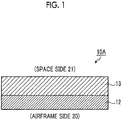
- Fig. 1 is a schematic sectional view showing a configuration example of a flexible thermal-control material according to Example 1.
- a flexible thermal-control material 10A according to the example includes a reflection layer 12 and an infrared radiation layer 13.
- the reflection layer 12 is provided on an adherend side (lower side of the drawing) and the infrared radiation layer 13 is provided on the outer side (upper side of the drawing) of the reflection layer 12. That is, in the example of the drawing, the reflection layer 12 is provided on an airframe side 20 which is the adherend and the infrared radiation layer 13 is provided as a surface of a space side 21. That is, in this example, the infrared radiation layer 13 is set as a layer exposed to space.
- the reflection layer 12 is preferably a high-reflectivity material layer. Accordingly, it is possible to reduce heat input to the airframe, by reflecting solar light.
- the high-reflectivity material layer is a layer configured with a material called high-reflectivity metal.
- high-reflectivity metal silver (Ag), aluminum (A1), and gold (Au) can be used, for example, but the specific examples are not limited thereto.
- an alloy, a compound, or a composite material thereof can be used, in addition to the simple substance of metal elements.
- the infrared radiation layer 13 is a layer having a function of radiating heat to space without absorbing solar light which is reflected by the reflection layer 12. Since space is in a vacuum state without oxygen, heat transfer due to radiation which does not require a heat transfer medium, is dominantly performed. Heat of the airframe side 20 is more easily radiated to space, as infrared emissivity increases. Accordingly, in the infrared radiation layer 13, as absorption of a solar light wavelength region is small and infrared emissivity is great, it is possible to prevent an increase in temperature of the airframe.
- the infrared radiation layer 13 is a layer configured with a silicone layer such as a silicone resin.
- a silicone material a polymer substance having a siloxane bond (Si-O-Si) as a main skeleton, such as a silicone resin, a silicone rubber, or silsesquioxane are also included.
- a silicone resin and a silicone rubber are provided as a material including an organic group in both ends of silicon (Si) and silsesquioxane is provided as a material including an organic group and oxygen in respective ends of silicon (Si).
- the silicone material As the infrared radiation layer 13, it is possible to ensure sufficient transparency for solar light to be incident to the reflection layer 12 and to ensure radioactive properties for radiating heat of the flexible thermal-control material to space.
- the silicone material has excellent radiation resistance and resistance to atomic oxygen, and accordingly, it is possible to realize a flexible thermal-control material which hardly causes performance degradation due to the space environment, by using the silicone material as the infrared radiation layer 13.
- a thickness of the infrared radiation layer 13 is preferably from 50 ⁇ m to 150 ⁇ m. In this range, excellent balance between a solar absorptance coefficient ( ⁇ ) and a total semi-sphere infrared emissivity ( ⁇ ) is obtained.
- the configuration described above it is possible to realize a flexible thermal-control material having excellent balance in which the solar absorptance coefficient ( ⁇ ) is equal to or less than 0.2 and the total semi-sphere infrared emissivity ( ⁇ ) is equal to or greater than 0.8.
- the control effect of an increase in temperature of the airframe decreases, it is also possible to set the thickness of the infrared radiation layer 13 to be smaller than 50 ⁇ m, if it is in an acceptable range in thermal design.
- thermo-control film By using a silicone material having excellent radiation resistance and resistance to atomic oxygen, it is possible to improve radiation resistance and resistance to atomic oxygen of the entire thermal-control material (thermal-control film) and to provide a flexible thermal-control material which hardly causes performance degradation in space.
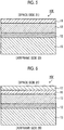
- Fig. 2A is a schematic sectional view showing a configuration example of a flexible thermal-control material according to Example 2.
- the infrared radiation layer 13 of a flexible thermal-control material 10B-1 of the example includes a silicone layer 13a and a pressure sensitive adhesive layer 13b.
- the pressure sensitive adhesive layer 13b is provided between the silicone layer 13a and the reflection layer 12 and is a layer for bonding both layers.
- the same reference numerals are used for the same constituent elements as those in Example 1 and the description thereof will be omitted.
- the silicone layer 13a is a layer having a silicone material such as a silicone resin as a component.
- a silicone material such as a silicone resin as a component.
- the silicone material has excellent radiation resistance and resistance to atomic oxygen, and accordingly, it is possible to realize a flexible thermal-control material 10B-1 which hardly causes performance degradation due to the space environment, by using the silicone layer 13a containing a silicone material as the infrared radiation layer 13.
- the pressure sensitive adhesive layer 13b is preferably configured with a silicone-based pressure sensitive adhesive. This is because the silicone-based adhesive has excellent adhesiveness with the silicone layer 13a and excellent heat resistance, radiation resistance, and resistance to atomic oxygen in space.
- the silicone-based pressure sensitive adhesive is a pressure sensitive adhesive having silicone as a base. Any of an addition reaction type and a peroxide-curing type may be used.
- the silicone layer 13a and the pressure sensitive adhesive layer 13b are common in that both layers have a polymer substance having a siloxane bond as a main skeleton, as a material, and both layers may be configured as separate bodies or may be integrally configured.
- the layers are integrally configured in the example of Fig. 1 and the layers are configured as separate bodies in the example of Fig. 2 .
- a thickness of the pressure sensitive adhesive layer 13b is, for example, from 10 ⁇ m to 100 ⁇ m, when the thickness of the entire infrared radiation layer 13 is from 50 ⁇ m to 300 ⁇ m.
- the pressure sensitive adhesive layer As a silicone-based pressure sensitive adhesive layer, it is possible to excellently bond the infrared radiation layer and the reflection layer to each other without disturbing solar absorptance coefficient ( ⁇ ), the total semi-sphere infrared emissivity (e), radiation resistance, and resistance to atomic oxygen which are properties of the silicone material-made infrared radiation layer.
- Fig. 2B is a schematic sectional view showing a configuration example of another flexible thermal-control material according to Example 2.
- a silsesquioxane layer 13c is provided on the outer side (upper side of the drawing) of the reflection layer 12.
- silsesquioxane layer 13c As the infrared radiation layer 13, it is possible to ensure sufficient transparency for solar light to be incident to the reflection layer 12. Accordingly, by using the silsesquioxane layer 13c as the infrared radiation layer 13, it is possible to realize the flexible thermal-control material 10B-2 which hardly causes performance degradation due to the space environment.
- the silsesquioxane layer 13c can be applied to the reflection layer 12 to form a coating layer by ultraviolet curing or thermal curing, for example.
- a coating thickness of the silsesquioxane layer 13c can be set to be equal to or smaller than 10 ⁇ m, the solar absorptance coefficient ( ⁇ ) is equal to or less than 0.1, and low cost can be realized.
- silsesquioxane layer 13c It is preferable to form the silsesquioxane layer 13c, because resistance to atomic oxygen is high in the silicone material and no tackiness is obtained.
- Fig. 3 is a schematic sectional view showing a configuration example of a flexible thermal-control material according to Example 3.
- a flexible thermal-control material 10C is formed by further laminating an antioxidant layer 14 on a surface of the reflection layer 12 on the side opposite to the surface where the infrared radiation layer 13 is laminated, in the flexible thermal-control material 10B-1 according to Example 2. That is, the antioxidant layer 14 is further provided on the lower side of the reflection layer 12 (lower side of the drawing), that is, on the airframe side 20 of the structure coated with the flexible thermal-control material 10c.
- the same reference numerals are used for the same constituent elements as those in Example 1 or Example 2 and the description thereof will be omitted.
- the antioxidant layer 14 for example, can be configured with a nickel-base superalloy (inconel or the like), chromium, nickel, and gold (vapor deposition on an aluminum surface).
- a nickel-base superalloy is particularly preferable, from viewpoints of anti-oxidation properties and corrosion resistance.
- the antioxidant layer is preferably provided between the reflection layer and the support layer.
- Fig. 4 is a schematic sectional view showing a configuration example of a flexible thermal-control material according to Example 4.
- a flexible thermal-control material 10D is formed by further laminating a support layer 15 on a surface of the reflection layer 12 on the side opposite to the surface where the infrared radiation layer 13 is laminated, in the flexible thermal-control material 10A according to Example 1. That is, the support layer 15 is further provided on the lower side of the reflection layer 12 (lower side of the drawing), that is, on the structure (adherend) side coated with the flexible thermal-control material 10D.
- the support layer 15 has a function and an effect of preventing generation of such cracks. This is for improving hardness or strength of the entire flexible thermal-control material 10D by the support layer 15.
- a polyimide material such as a polyimide resin from viewpoints of strength and heat resistance.
- a polyester material such as polyethylene-telephthalate (PET), which is a material having a function and an effect of preventing generation of cracks or tears on the reflection layer and the infrared radiation layer may be used.
- Fig. 5 is a schematic sectional view showing a configuration example of a flexible thermal-control material according to Example 5.
- a flexible thermal-control material 10E is formed by further laminating a protection layer 16 on a surface of the infrared radiation layer 13 on the side opposite to the surface where the reflection layer 12 is laminated, in the flexible thermal-control material 10D according to Example 4. That is, the protection layer 16 is further provided on the upper side of the infrared radiation layer 13 (upper side of the drawing), that is, on the space side 21.
- the protection layer 16 covers the surface of the silicone material having high tackiness (stickiness) so as to provide a function and an effect of preventing surface contamination of the flexible thermal-control material 10E.
- a propellant tank of the rocket becomes an adherend, and the outer surface of the propellant tank of the rocket is coated with the flexible thermal-control material.
- the protection layer 16 is provided on the surface of the silicone material layer so as to provide a function and an effect of preventing surface contamination of the flexible thermal-control material 10E from the application of the material to the rocket fire.
- the protection layer 16 it is preferable to configure silsesquioxane having higher resistance to atomic oxygen among the silicone materials. It is possible to obtain higher resistance to atomic oxygen, by coating the surface of the flexible thermal-control material with silsesquioxane.
- Fig. 6 is a schematic sectional view showing a configuration example of a flexible thermal-control material according to Example 6.
- a flexible thermal-control material 10F is formed by further laminating a conductive layer 17 on the protection layer 16 in the flexible thermal-control material 10E according to Example 5. That is, the conductive layer 17 is further provided on the surface of the protection layer 16, that is, the outermost surface on the space side 21.
- the conductive layer 17 has a function and an effect of preventing damage to the flexible thermal-control material 10F due to an electric discharge.
- the conductive layer 17 is preferably a transparent conductive layer having transparency so as to allow solar light to be incident to the reflection layer 12.
- a metal compound material having conductivity such as indium tin oxide (ITO), antimony tin oxide (ATO), or TiO 2 (titanium dioxide) doped with Nb, or carbon-based material such as carbon nanotube can be used.
- ITO indium tin oxide
- ATO antimony tin oxide
- TiO 2 titanium dioxide
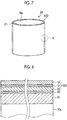
- Fig. 7 is a schematic view showing an example of applying the flexible thermal-control material on an adherend.
- an adherend is a propellant tank (for example, liquid hydrogen tank) of a rocket.
- Figs. 8 to 10 are enlarged schematic sectional views showing an enlarged A part of Fig. 7 .
- a surface of a tank main body 30a of a propellant tank 30 such as a liquid hydrogen tank is coated with the flexible thermal-control material 10D according to Example 4.
- a polyisocyanurate foam (PIF) heat insulating layer (hereinafter, referred to as a "PIF heat insulating layer”) 31 is formed on the surface of the propellant tank and the flexible thermal-control material 10D is applied to the surface thereof.
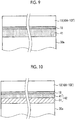
- Fig. 8 is a diagram specifically illustrating a relationship between the surface of the propellant tank of Fig. 7 , that is, the PIF heat insulating layer 31, and the flexible thermal-control material 10D.
- the flexible thermal-control material 10D in which the reflection layer 12 is laminated on the support layer 15 and the infrared radiation layer 13 is further laminated on the surface thereof, is adhered onto the PIF heat insulating layer 31 through a bonding layer 18 and covers the tank main body 30a.
- the bonding layer 18 is a layer configured with a pressure sensitive adhesive or an adhesive, for example.
- a pressure sensitive adhesive or an adhesive a material which hardly causes generation of gas in a vacuum environment as in space is preferable.
- the flexible thermal-control material 10D is adhered to the PIF heat insulating layer 31 on the surface of the liquid hydrogen tank by the bonding layer 18, but the flexible thermal-control material 10D can also be adhered to the surface of the liquid hydrogen tank by a fastening member.
- a fastening member a fastener for fastening and fixing a component to another component can be used, for example.
- a rivet can be used, for example, as the fastener.
- Fig. 9 is a diagram in which the flexible thermal-control material 10 (10A to 10F) is provided by the bonding layer 18 using a polyimide foam heat insulating layer 41, instead of the PIF heat insulating layer 31 of Fig. 8 .
- the polyimide foam heat insulating layer 41 is a foam in which air bubbles have an open-cell structure and exhibits an effect of vacuum insulation.
- a thickness of the polyimide foam heat insulating layer 41 is, for example, preferably approximately from 10 mm to 50 mm.
- Fig. 10 is a diagram in which the flexible thermal-control material 10 (10A to 10F) is provided on a heat insulating layer 42 having a laminated body structure of two layers which are the PIF heat insulating layer 31 of Fig. 8 and the polyimide foam heat insulating layer 41.
- the polyimide foam heat insulating layer 41 is a foam in which air bubbles have an open-cell structure and exhibits an effect of vacuum insulation.
- a thickness of the heat insulating layer 42 of two layers which are the PIF heat insulating layer 31 and the polyimide foam heat insulating layer 41 is, for example, preferably approximately from 10 mm to 50 mm.
- the PIF heat insulating layer 31 is provided on the tank main body 30a side, but the polyimide foam heat insulating layer 41 side may be set as the tank main body 30a side and the PIF heat insulating layer 31 may be provided on the upper layer thereof.
- Fig. 11 is a diagram showing an example of a schematic view of a rocket.
- a satellite 53 is provided on a head portion side of a liquid hydrogen tank 51 which is a propellant tank through a pedestal 52.
- a liquid oxygen tank 55 is provided on a rear side of the liquid hydrogen tank 51 through a rod 54 and performs a supply operation to an engine 56 side.
- Fig. 12A is a sectional view in a longitudinal direction of a flexible thermal-control material which is applied on a liquid hydrogen tank and Fig. 12B is a B-B line sectional view of Fig. 12A .
- the PIF heat insulating layer 31 is formed on the surface of the liquid hydrogen tank 51 and the flexible thermal-control material 10 (10A to 10F) according to Examples described above is coated on the surface of the PIF heat insulating layer 31.
- the flexible thermal-control material 10 (10A to 10E) is the same material as in examples 1 to 6 and the description thereof will be omitted.
- a degassing groove 32 is formed along an axial direction of the PIF heat insulating layer 31 and perform degassing of exhaust gas (for example, low molecular component) 33 generated in the PIF heat insulating layer 31.
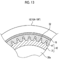
- Fig. 13 is a sectional view of another flexible thermal-control material of the example which is applied on a liquid hydrogen tank.
- the heat insulating layer 42 having a two-layered structure of the PIF heat insulating layer 31 and the polyimide foam heat insulating layer 41 is provided on the surface of the tank main body 30a of the liquid hydrogen tank 51 and the flexible thermal-control material 10 (10A to 10E) according to Examples described above is coated on the surface of the heat insulating layer 42 having a two-layered structure.
- the degassing groove 32 is continuously formed along an axial direction of in a boundary between the PIF heat insulating layer 31 and the polyimide foam heat insulating layer 41 and performs degassing of exhaust gas (for example, low molecular component) generated in the heat insulating layer 42.
- the degassing groove 32 is formed by setting a boundary surface between the PIF heat insulating layer 31 and the polyimide foam heat insulating layer 41 as an approximate gear wheel structure, but the invention is not limited thereto.
Landscapes
- Engineering & Computer Science (AREA)
- Physics & Mathematics (AREA)
- Remote Sensing (AREA)
- Aviation & Aerospace Engineering (AREA)
- General Physics & Mathematics (AREA)
- Combustion & Propulsion (AREA)
- Chemical & Material Sciences (AREA)
- Thermal Sciences (AREA)
- Health & Medical Sciences (AREA)
- Critical Care (AREA)
- Emergency Medicine (AREA)
- General Health & Medical Sciences (AREA)
- Optics & Photonics (AREA)
- Astronomy & Astrophysics (AREA)
- Laminated Bodies (AREA)
Abstract
Description
- The present invention relates to a flexible thermal-control material.
- In order to prevent an increase in temperature of an airframe due to incidence of solar light, a surface of an artificial satellite or a rocket used in space is coated with a thermal-control material having a function of reflecting the solar light and radiating thermal energy of the solar light to space.
- A flexible thermal-control material, a so-called flexible optical solar reflector (OSR), having flexibility which is easily processed according to a surface shape of the airframe or a structure to be coated, is paid attention as the thermal-control material.
-
PTL 1 discloses a flexible thermal-control material including a metal layer on a polyimide film. InPTL 1, the surface of the polyimide film is subjected to roughening treatment, and accordingly secondary reflection of solar light is prevented and reflectivity and diffuseness are improved. - [PTL 1]
Japanese Unexamined Patent Application Publication No. 2007-253399 - However, in the flexible thermal-control material used in space, applicability in various space missions and particularly low optical properties in a solar absorptance coefficient (α) are required.
- It is required that a low solar absorptance coefficient (α) and a high total semi-sphere infrared emissivity (ε) are satisfied, and in order to realize long-term use in space, it is required that all conditions of high tolerance to radiation and high tolerance to atomic oxygen in space are satisfied.
- However, the flexible thermal-control material disclosed in
PTL 1 does not satisfy the conditions of the optical properties. - The present invention has been made to address the aforementioned problems and provide a flexible thermal-control material having excellent optical properties when it is used in space.
- The invention provides a flexible thermal-control material configured by laminating a reflection layer which reflects solar light and an infrared radiation layer which radiates infrared light, and the infrared radiation layer is configured with a silicone material.
- In the flexible thermal-control material, it is preferable that the infrared radiation layer includes a silicone layer configured with a silicone material and a pressure sensitive adhesive layer, and the pressure sensitive adhesive layer is provided between the silicone layer and the reflection layer.
- In the flexible thermal-control material, it is preferable that the pressure sensitive adhesive layer is a silicone-based pressure sensitive adhesive layer.
- In the flexible thermal-control material, it is preferable that a support layer is further laminated on a surface of the reflection layer on the side opposite to the surface where the infrared radiation layer is laminated.
- In the flexible thermal-control material, it is preferable that a protection layer is further laminated on a surface of the infrared radiation layer on the side opposite to the surface where the reflection layer is laminated.
- In the flexible thermal-control material, it is preferable that a conductive layer is further laminated on the protection layer.
- In the flexible thermal-control material, it is preferable that an antioxidant layer is further laminated on a surface of the reflection layer on the side opposite to the surface where the infrared radiation layer is laminated.
- In the flexible thermal-control material, it is preferable that the antioxidant layer is provided between the reflection layer and the support layer.
- In the flexible thermal-control material, it is preferable that the flexible thermal-control material is fixed to a surface of an adherend by a bonding layer or a fastening member.
- In the flexible thermal-control material, it is preferable that the adherend is a propellant tank of a rocket or an artificial satellite used in space.
- In the flexible thermal-control material, it is preferable that the propellant tank is a liquid hydrogen tank.
- In the flexible thermal-control material, it is preferable that a surface of the adherend is any one of a polyisocyanurate foam (PIF) heat insulating layer and a polyimide foam heat insulating layer or a heat insulating layer of a laminated body thereof.
- In the flexible thermal-control material, it is preferable that the surface of the adherend includes a degassing groove in any one of a polyisocyanurate foam (PIF) heat insulating layer and a polyimide foam heat insulating layer or a heat insulating layer of a laminated body thereof.
- The invention exhibits an effect of providing a flexible thermal-control material having excellent optical properties such as a solar absorptance coefficient (α). Brief Description of Drawings
-
-
Fig. 1 is a schematic sectional view showing a configuration example of a flexible thermal-control material according to Example 1. -
Fig. 2A is a schematic sectional view showing a configuration example of a flexible thermal-control material according to Example 2. -
Fig. 2B is a schematic sectional view showing a configuration example of another flexible thermal-control material according to Example 2. -
Fig. 3 is a schematic sectional view showing a configuration example of a flexible thermal-control material according to Example 3. -
Fig. 4 is a schematic sectional view showing a configuration example of a flexible thermal-control material according to Example 4. -
Fig. 5 is a schematic sectional view showing a configuration example of a flexible thermal-control material according to Example 5. -
Fig. 6 is a schematic sectional view showing a configuration example of a flexible thermal-control material according to Example 6. -
Fig. 7 is a schematic view showing an example of applying the flexible thermal-control material on an adherend. -
Fig. 8 is an enlarged schematic sectional view showing an enlarged A part ofFig. 7 . -
Fig. 9 is an enlarged schematic sectional view showing an enlarged A part ofFig. 7 . -
Fig. 10 is an enlarged schematic sectional view showing an enlarged A part ofFig. 7 . -
Fig. 11 is a diagram showing an example of a schematic view of a rocket. -
Fig. 12A is a sectional view in a longitudinal direction of a flexible thermal-control material which is applied on a liquid hydrogen tank. -
Fig. 12B is a B-B line sectional view ofFig. 12A . -
Fig. 13 is a sectional view of another flexible thermal-control material of the example which is applied on a liquid hydrogen tank. - Hereinafter, the invention will be described with reference to the accompanied drawings. The invention is not limited to the following embodiments or examples. In addition, constituent elements of the following embodiments or examples include constituent elements which can be and are easily replaced by a person skilled in the art, or the same constituent elements.
-
Fig. 1 is a schematic sectional view showing a configuration example of a flexible thermal-control material according to Example 1. As shown inFig. 1 , a flexible thermal-control material 10A according to the example includes areflection layer 12 and aninfrared radiation layer 13. In the example offig. 1 , thereflection layer 12 is provided on an adherend side (lower side of the drawing) and theinfrared radiation layer 13 is provided on the outer side (upper side of the drawing) of thereflection layer 12. That is, in the example of the drawing, thereflection layer 12 is provided on anairframe side 20 which is the adherend and theinfrared radiation layer 13 is provided as a surface of aspace side 21. That is, in this example, theinfrared radiation layer 13 is set as a layer exposed to space. - The
reflection layer 12 is preferably a high-reflectivity material layer. Accordingly, it is possible to reduce heat input to the airframe, by reflecting solar light. Herein, the high-reflectivity material layer is a layer configured with a material called high-reflectivity metal. As specific examples of such high-reflectivity metal, silver (Ag), aluminum (A1), and gold (Au) can be used, for example, but the specific examples are not limited thereto. In addition, as the high-reflectivity metal, an alloy, a compound, or a composite material thereof can be used, in addition to the simple substance of metal elements. - The
infrared radiation layer 13 is a layer having a function of radiating heat to space without absorbing solar light which is reflected by thereflection layer 12. Since space is in a vacuum state without oxygen, heat transfer due to radiation which does not require a heat transfer medium, is dominantly performed. Heat of theairframe side 20 is more easily radiated to space, as infrared emissivity increases. Accordingly, in theinfrared radiation layer 13, as absorption of a solar light wavelength region is small and infrared emissivity is great, it is possible to prevent an increase in temperature of the airframe. - The
infrared radiation layer 13 is a layer configured with a silicone layer such as a silicone resin. As the silicone material, a polymer substance having a siloxane bond (Si-O-Si) as a main skeleton, such as a silicone resin, a silicone rubber, or silsesquioxane are also included. Here, a silicone resin and a silicone rubber are provided as a material including an organic group in both ends of silicon (Si) and silsesquioxane is provided as a material including an organic group and oxygen in respective ends of silicon (Si). - By using the silicone material as the
infrared radiation layer 13, it is possible to ensure sufficient transparency for solar light to be incident to thereflection layer 12 and to ensure radioactive properties for radiating heat of the flexible thermal-control material to space. In addition, the silicone material has excellent radiation resistance and resistance to atomic oxygen, and accordingly, it is possible to realize a flexible thermal-control material which hardly causes performance degradation due to the space environment, by using the silicone material as theinfrared radiation layer 13. - A thickness of the
infrared radiation layer 13 is preferably from 50 µm to 150 µm. In this range, excellent balance between a solar absorptance coefficient (α) and a total semi-sphere infrared emissivity (ε) is obtained. - According to the configuration described above, it is possible to realize a flexible thermal-control material having excellent balance in which the solar absorptance coefficient (α) is equal to or less than 0.2 and the total semi-sphere infrared emissivity (ε) is equal to or greater than 0.8. Although the control effect of an increase in temperature of the airframe decreases, it is also possible to set the thickness of the
infrared radiation layer 13 to be smaller than 50 µm, if it is in an acceptable range in thermal design. - By using a silicone material having excellent radiation resistance and resistance to atomic oxygen, it is possible to improve radiation resistance and resistance to atomic oxygen of the entire thermal-control material (thermal-control film) and to provide a flexible thermal-control material which hardly causes performance degradation in space.
- According to the configuration described above, it is possible to provide a flexible thermal-control material which is excellently adhered to various structures which is an adherend. In addition, by setting a roll molded body by winding the sheet-like flexible thermal-control material around a core, it is possible to perform the application to an adherend having a cylindrical outer shape.
-
Fig. 2A is a schematic sectional view showing a configuration example of a flexible thermal-control material according to Example 2. As shown inFig. 2A , theinfrared radiation layer 13 of a flexible thermal-control material 10B-1 of the example includes asilicone layer 13a and a pressure sensitiveadhesive layer 13b. The pressure sensitiveadhesive layer 13b is provided between thesilicone layer 13a and thereflection layer 12 and is a layer for bonding both layers. In the example, the same reference numerals are used for the same constituent elements as those in Example 1 and the description thereof will be omitted. - The
silicone layer 13a is a layer having a silicone material such as a silicone resin as a component. By using thesilicone layer 13a as theinfrared radiation layer 13, it is possible to ensure sufficient transparency for solar light to be incident to thereflection layer 12 and to ensure radioactive properties for radiating heat energy of solar light to space. In addition, the silicone material has excellent radiation resistance and resistance to atomic oxygen, and accordingly, it is possible to realize a flexible thermal-control material 10B-1 which hardly causes performance degradation due to the space environment, by using thesilicone layer 13a containing a silicone material as theinfrared radiation layer 13. - The pressure sensitive
adhesive layer 13b is preferably configured with a silicone-based pressure sensitive adhesive. This is because the silicone-based adhesive has excellent adhesiveness with thesilicone layer 13a and excellent heat resistance, radiation resistance, and resistance to atomic oxygen in space. - The silicone-based pressure sensitive adhesive is a pressure sensitive adhesive having silicone as a base. Any of an addition reaction type and a peroxide-curing type may be used.
- The
silicone layer 13a and the pressure sensitiveadhesive layer 13b are common in that both layers have a polymer substance having a siloxane bond as a main skeleton, as a material, and both layers may be configured as separate bodies or may be integrally configured. The layers are integrally configured in the example ofFig. 1 and the layers are configured as separate bodies in the example ofFig. 2 . - A thickness of the pressure sensitive
adhesive layer 13b is, for example, from 10 µm to 100 µm, when the thickness of the entireinfrared radiation layer 13 is from 50 µm to 300 µm. - According to the configuration described above, it is possible to realize a flexible thermal-control material having excellent balance between the solar absorptance coefficient (α) and the total semi-sphere infrared emissivity (e). By setting the pressure sensitive adhesive layer as a silicone-based pressure sensitive adhesive layer, it is possible to excellently bond the infrared radiation layer and the reflection layer to each other without disturbing solar absorptance coefficient (α), the total semi-sphere infrared emissivity (e), radiation resistance, and resistance to atomic oxygen which are properties of the silicone material-made infrared radiation layer.
-
Fig. 2B is a schematic sectional view showing a configuration example of another flexible thermal-control material according to Example 2. As shown inFig. 2B , in theinfrared radiation layer 13 of a flexible thermal-control material 10B-2 of the example, asilsesquioxane layer 13c is provided on the outer side (upper side of the drawing) of thereflection layer 12. - By using the
silsesquioxane layer 13c as theinfrared radiation layer 13, it is possible to ensure sufficient transparency for solar light to be incident to thereflection layer 12. Accordingly, by using thesilsesquioxane layer 13c as theinfrared radiation layer 13, it is possible to realize the flexible thermal-control material 10B-2 which hardly causes performance degradation due to the space environment. - The
silsesquioxane layer 13c can be applied to thereflection layer 12 to form a coating layer by ultraviolet curing or thermal curing, for example. A coating thickness of thesilsesquioxane layer 13c can be set to be equal to or smaller than 10 µm, the solar absorptance coefficient (α) is equal to or less than 0.1, and low cost can be realized. - It is preferable to form the
silsesquioxane layer 13c, because resistance to atomic oxygen is high in the silicone material and no tackiness is obtained. -
Fig. 3 is a schematic sectional view showing a configuration example of a flexible thermal-control material according to Example 3. As shown inFig. 3 , a flexible thermal-control material 10C is formed by further laminating anantioxidant layer 14 on a surface of thereflection layer 12 on the side opposite to the surface where theinfrared radiation layer 13 is laminated, in the flexible thermal-control material 10B-1 according to Example 2. That is, theantioxidant layer 14 is further provided on the lower side of the reflection layer 12 (lower side of the drawing), that is, on theairframe side 20 of the structure coated with the flexible thermal-control material 10c. In the example, the same reference numerals are used for the same constituent elements as those in Example 1 or Example 2 and the description thereof will be omitted. - The
antioxidant layer 14, for example, can be configured with a nickel-base superalloy (inconel or the like), chromium, nickel, and gold (vapor deposition on an aluminum surface). Among these, a nickel-base superalloy is particularly preferable, from viewpoints of anti-oxidation properties and corrosion resistance. - According to the configuration described above, it is possible to further improve an anti-oxidation effect by atomic oxygen in space. In addition to the configuration of the example, in a case of providing a support layer, the antioxidant layer is preferably provided between the reflection layer and the support layer.
-
Fig. 4 is a schematic sectional view showing a configuration example of a flexible thermal-control material according to Example 4. As shown inFig. 4 , a flexible thermal-control material 10D is formed by further laminating asupport layer 15 on a surface of thereflection layer 12 on the side opposite to the surface where theinfrared radiation layer 13 is laminated, in the flexible thermal-control material 10A according to Example 1. That is, thesupport layer 15 is further provided on the lower side of the reflection layer 12 (lower side of the drawing), that is, on the structure (adherend) side coated with the flexible thermal-control material 10D. - If a tensile force is loaded when applying the flexible thermal-control material onto the adherend, cracks may be generated on the
infrared radiation layer 13 or thereflection layer 12. Thesupport layer 15 has a function and an effect of preventing generation of such cracks. This is for improving hardness or strength of the entire flexible thermal-control material 10D by thesupport layer 15. - As the
support layer 15, it is preferable to use a polyimide material such as a polyimide resin from viewpoints of strength and heat resistance. Alternatively, a polyester material such as polyethylene-telephthalate (PET), which is a material having a function and an effect of preventing generation of cracks or tears on the reflection layer and the infrared radiation layer may be used. - According to the configuration described above, it is possible to apply suitable hardness or strength to the flexible thermal-control material so as to be applied. Accordingly, it is possible to prevent generation of cracks on the
reflection layer 12, when attaching or bonding the flexible thermal-control material to a structure (airframe) such as a rocket or an artificial satellite. -
Fig. 5 is a schematic sectional view showing a configuration example of a flexible thermal-control material according to Example 5. As shown inFig. 5 , a flexible thermal-control material 10E is formed by further laminating aprotection layer 16 on a surface of theinfrared radiation layer 13 on the side opposite to the surface where thereflection layer 12 is laminated, in the flexible thermal-control material 10D according to Example 4. That is, theprotection layer 16 is further provided on the upper side of the infrared radiation layer 13 (upper side of the drawing), that is, on thespace side 21. - The
protection layer 16 covers the surface of the silicone material having high tackiness (stickiness) so as to provide a function and an effect of preventing surface contamination of the flexible thermal-control material 10E. For example, when applying the flexible thermal-control material to a rocket, a propellant tank of the rocket becomes an adherend, and the outer surface of the propellant tank of the rocket is coated with the flexible thermal-control material. In this case, theprotection layer 16 is provided on the surface of the silicone material layer so as to provide a function and an effect of preventing surface contamination of the flexible thermal-control material 10E from the application of the material to the rocket fire. - As the
protection layer 16, it is preferable to configure silsesquioxane having higher resistance to atomic oxygen among the silicone materials. It is possible to obtain higher resistance to atomic oxygen, by coating the surface of the flexible thermal-control material with silsesquioxane. -
Fig. 6 is a schematic sectional view showing a configuration example of a flexible thermal-control material according to Example 6. As shown inFig. 6 , a flexible thermal-control material 10F is formed by further laminating aconductive layer 17 on theprotection layer 16 in the flexible thermal-control material 10E according to Example 5. That is, theconductive layer 17 is further provided on the surface of theprotection layer 16, that is, the outermost surface on thespace side 21. - The
conductive layer 17 has a function and an effect of preventing damage to the flexible thermal-control material 10F due to an electric discharge. In addition, theconductive layer 17 is preferably a transparent conductive layer having transparency so as to allow solar light to be incident to thereflection layer 12. - As the
conductive layer 17, a metal compound material having conductivity such as indium tin oxide (ITO), antimony tin oxide (ATO), or TiO2 (titanium dioxide) doped with Nb, or carbon-based material such as carbon nanotube can be used. - According to the configuration described above, it is possible to provide a flexible thermal-control material having reduced risk of damage due to an electric discharge.
-
Fig. 7 is a schematic view showing an example of applying the flexible thermal-control material on an adherend. In the example of the drawing, an adherend is a propellant tank (for example, liquid hydrogen tank) of a rocket.Figs. 8 to 10 are enlarged schematic sectional views showing an enlarged A part ofFig. 7 . - In the example of the laminated body shown in
Fig. 7 , a surface of a tankmain body 30a of apropellant tank 30 such as a liquid hydrogen tank is coated with the flexible thermal-control material 10D according to Example 4. Herein, a polyisocyanurate foam (PIF) heat insulating layer (hereinafter, referred to as a "PIF heat insulating layer") 31 is formed on the surface of the propellant tank and the flexible thermal-control material 10D is applied to the surface thereof. -
Fig. 8 is a diagram specifically illustrating a relationship between the surface of the propellant tank ofFig. 7 , that is, the PIFheat insulating layer 31, and the flexible thermal-control material 10D. As shown inFig. 8 , the flexible thermal-control material 10D in which thereflection layer 12 is laminated on thesupport layer 15 and theinfrared radiation layer 13 is further laminated on the surface thereof, is adhered onto the PIFheat insulating layer 31 through abonding layer 18 and covers the tankmain body 30a. - The
bonding layer 18 is a layer configured with a pressure sensitive adhesive or an adhesive, for example. As a pressure sensitive adhesive or an adhesive, a material which hardly causes generation of gas in a vacuum environment as in space is preferable. - In the embodiment, the flexible thermal-
control material 10D is adhered to the PIFheat insulating layer 31 on the surface of the liquid hydrogen tank by thebonding layer 18, but the flexible thermal-control material 10D can also be adhered to the surface of the liquid hydrogen tank by a fastening member. As the fastening member, a fastener for fastening and fixing a component to another component can be used, for example. A rivet can be used, for example, as the fastener. -
Fig. 9 is a diagram in which the flexible thermal-control material 10 (10A to 10F) is provided by thebonding layer 18 using a polyimide foamheat insulating layer 41, instead of the PIFheat insulating layer 31 ofFig. 8 . The polyimide foamheat insulating layer 41 is a foam in which air bubbles have an open-cell structure and exhibits an effect of vacuum insulation. A thickness of the polyimide foamheat insulating layer 41 is, for example, preferably approximately from 10 mm to 50 mm. -
Fig. 10 is a diagram in which the flexible thermal-control material 10 (10A to 10F) is provided on aheat insulating layer 42 having a laminated body structure of two layers which are the PIFheat insulating layer 31 ofFig. 8 and the polyimide foamheat insulating layer 41. - The polyimide foam
heat insulating layer 41 is a foam in which air bubbles have an open-cell structure and exhibits an effect of vacuum insulation. A thickness of theheat insulating layer 42 of two layers which are the PIFheat insulating layer 31 and the polyimide foamheat insulating layer 41 is, for example, preferably approximately from 10 mm to 50 mm. - In the example, the PIF
heat insulating layer 31 is provided on the tankmain body 30a side, but the polyimide foamheat insulating layer 41 side may be set as the tankmain body 30a side and the PIFheat insulating layer 31 may be provided on the upper layer thereof. -
Fig. 11 is a diagram showing an example of a schematic view of a rocket. As shown inFig. 11 , asatellite 53 is provided on a head portion side of aliquid hydrogen tank 51 which is a propellant tank through apedestal 52. Aliquid oxygen tank 55 is provided on a rear side of theliquid hydrogen tank 51 through arod 54 and performs a supply operation to anengine 56 side. -
Fig. 12A is a sectional view in a longitudinal direction of a flexible thermal-control material which is applied on a liquid hydrogen tank andFig. 12B is a B-B line sectional view ofFig. 12A . - In the example, the PIF
heat insulating layer 31 is formed on the surface of theliquid hydrogen tank 51 and the flexible thermal-control material 10 (10A to 10F) according to Examples described above is coated on the surface of the PIFheat insulating layer 31. The flexible thermal-control material 10 (10A to 10E) is the same material as in examples 1 to 6 and the description thereof will be omitted. - In the example, a degassing
groove 32 is formed along an axial direction of the PIFheat insulating layer 31 and perform degassing of exhaust gas (for example, low molecular component) 33 generated in the PIFheat insulating layer 31. - Accordingly, negative effects such as vapor deposition due to
exhaust gas 33 on the flexible thermal-control material 10 (10A to 10E) formed on the surface of the PIFheat insulating layer 31 or thesatellite 53 are prevented and thesatellite 53 is protected. -
Fig. 13 is a sectional view of another flexible thermal-control material of the example which is applied on a liquid hydrogen tank. - In the example, the
heat insulating layer 42 having a two-layered structure of the PIFheat insulating layer 31 and the polyimide foamheat insulating layer 41 is provided on the surface of the tankmain body 30a of theliquid hydrogen tank 51 and the flexible thermal-control material 10 (10A to 10E) according to Examples described above is coated on the surface of theheat insulating layer 42 having a two-layered structure. - In the example, the degassing
groove 32 is continuously formed along an axial direction of in a boundary between the PIFheat insulating layer 31 and the polyimide foamheat insulating layer 41 and performs degassing of exhaust gas (for example, low molecular component) generated in theheat insulating layer 42. The degassinggroove 32 is formed by setting a boundary surface between the PIFheat insulating layer 31 and the polyimide foamheat insulating layer 41 as an approximate gear wheel structure, but the invention is not limited thereto. - As described above, it is possible to suitably realize heat insulation in space which was insufficiently realized with only the PIF heat insulating layer, by coating the outer surface of the propellant tank of the rocket with the flexible thermal-control material according to the invention. In the related art, in a structure used in space such as a rocket or an artificial satellite, heat input from the outside is prevented by the PIF heat insulating layer and evaporation of liquid hydrogen which is propellant is prevented, but in space in a vacuum state without oxygen, heat input due to radiation is dominantly performed and sufficient heat insulating performance cannot be obtained with only the PIF heat insulating layer. It is possible to prevent problems regarding heat input due to radiation in space to improve heat insulating performance, by further coating the PIF surface with the flexible thermal-control material according to the invention.
-
- 10
- (10A to 10F) Flexible thermal-control material
- 12
- Reflection layer
- 13
- Infrared radiation layer
- 14
- Antioxidant layer
- 15
- Support layer
- 16
- Protection layer
- 17
- Conductive layer
- 18
- Bonding layer
- 20
- Airframe side (adherend side)
- 21
- Space side
- 30
- Propellant tank (adherend)
- 31
- PIF heat insulating layer
- 41
- Polyimide foam heat insulating layer
Claims (14)
- A flexible thermal-control material which is formed by laminating:a reflection layer which reflects solar light; andan infrared radiation layer which radiates infrared light,wherein the infrared radiation layer is configured with a silicone material.
- The flexible thermal-control material according to claim 1,
wherein the infrared radiation layer includes a silicone layer configured with a silicone material and a pressure sensitive adhesive layer, and
the pressure sensitive adhesive layer is provided between the silicone layer and the reflection layer. - The flexible thermal-control material according to claim 2,
wherein the pressure sensitive adhesive layer is a silicone-based pressure sensitive adhesive layer. - The flexible thermal-control material according to any one of claims 1 to 3,
wherein a support layer is further laminated on a surface of the reflection layer on the side opposite to the surface where the infrared radiation layer is laminated. - The flexible thermal-control material according to any one of claims 1 to 4,
wherein a protection layer is further laminated on a surface of the infrared radiation layer on the side opposite to the surface where the reflection layer is laminated. - The flexible thermal-control material according to claim 5,
wherein a conductive layer is further laminated on the protection layer. - The flexible thermal-control material according to any one of claims 1 to 6,
wherein an antioxidant layer is further laminated on a surface of the reflection layer on the side opposite to the surface where the infrared radiation layer is laminated. - The flexible thermal-control material according to claim 7,
wherein the antioxidant layer is provided between the reflection layer and the support layer. - The flexible thermal-control material according to any one of claims 1 to 8, which is fixed to a surface of an adherend by a bonding layer.
- The flexible thermal-control material according to any one of claims 1 to 9, which is fixed to a surface of an adherend by a fastening member.
- The flexible thermal-control material according to claim 9 or 10
wherein the adherend is a propellant tank of a rocket or an artificial satellite used in space. - The flexible thermal-control material according to claim 11,
wherein the propellant tank is a liquid hydrogen tank. - The flexible thermal-control material according to any one of claims 9 to 12,
wherein a surface of the adherend is any one of a polyisocyanurate foam (PIF) heat insulating layer and a polyimide foam heat insulating layer or a heat insulating layer of a laminated body thereof. - The flexible thermal-control material according to claim 13,
wherein the surface of the adherend includes a degassing groove in any one of a polyisocyanurate foam (PIF) heat insulating layer and a polyimide foam heat insulating layer or a heat insulating layer of a laminated body thereof.
Applications Claiming Priority (3)
| Application Number | Priority Date | Filing Date | Title |
|---|---|---|---|
| JP2013177362 | 2013-08-28 | ||
| JP2014072893A JP6539429B2 (en) | 2013-08-28 | 2014-03-31 | Flexible heat control material and propellant tank |
| PCT/JP2014/072240 WO2015029974A1 (en) | 2013-08-28 | 2014-08-26 | Flexible thermal-control material |
Publications (3)
| Publication Number | Publication Date |
|---|---|
| EP3015262A1 true EP3015262A1 (en) | 2016-05-04 |
| EP3015262A4 EP3015262A4 (en) | 2016-05-25 |
| EP3015262B1 EP3015262B1 (en) | 2020-11-04 |
Family
ID=52586531
Family Applications (1)
| Application Number | Title | Priority Date | Filing Date |
|---|---|---|---|
| EP14839959.5A Active EP3015262B1 (en) | 2013-08-28 | 2014-08-26 | Flexible thermal-control material |
Country Status (4)
| Country | Link |
|---|---|
| US (1) | US10220967B2 (en) |
| EP (1) | EP3015262B1 (en) |
| JP (1) | JP6539429B2 (en) |
| WO (1) | WO2015029974A1 (en) |
Cited By (1)
| Publication number | Priority date | Publication date | Assignee | Title |
|---|---|---|---|---|
| WO2019018001A1 (en) * | 2017-07-17 | 2019-01-24 | Raytheon Company | Three-dimensional multi-shell insulation |
Families Citing this family (11)
| Publication number | Priority date | Publication date | Assignee | Title |
|---|---|---|---|---|
| EP3000583A1 (en) * | 2014-09-29 | 2016-03-30 | Inergy Automotive Systems Research (Société Anonyme) | Vehicle component with heat shield and method for manufacturing the same |
| KR101732488B1 (en) | 2015-06-15 | 2017-05-04 | 한국과학기술원 | Impact-resistant flexible composite using shear-thickening fluid and shape-variable protection apparatus |
| WO2018029840A1 (en) * | 2016-08-10 | 2018-02-15 | 株式会社ispace | Probe |
| US20190152626A1 (en) * | 2017-11-22 | 2019-05-23 | The Boeing Company | Thermal control tape, system, and method for a spacecraft structure |
| US10583632B2 (en) * | 2018-01-11 | 2020-03-10 | Skeyeon, Inc. | Atomic oxygen-resistant, low drag coatings and materials |
| JP7320982B2 (en) * | 2019-05-09 | 2023-08-04 | 大阪瓦斯株式会社 | agricultural house |
| IT202000022435A1 (en) * | 2020-09-23 | 2022-03-23 | Leonardo Spa | MULTILAYER COATING FOR OPTICAL SOLAR REFLECTOR |
| CN112379472B (en) * | 2020-11-13 | 2022-08-16 | 上海卫星装备研究所 | Optical solar reflecting mirror with low radiation absorption ratio and preparation method thereof |
| WO2024247487A1 (en) * | 2023-05-31 | 2024-12-05 | 国立研究開発法人宇宙航空研究開発機構 | Coating composition, method for producing coated article, coated article, and silsesquioxane derivative |
| JP7607887B1 (en) * | 2024-02-27 | 2025-01-06 | 大阪瓦斯株式会社 | Resin laminated film |
| CN118907446B (en) * | 2024-07-01 | 2026-02-27 | 上海卫星工程研究所 | Integrated thermal control film for satellite heat dissipation |
Family Cites Families (33)
| Publication number | Priority date | Publication date | Assignee | Title |
|---|---|---|---|---|
| US3321154A (en) * | 1965-07-14 | 1967-05-23 | William R Downs | Transpirationally cooled heat ablation system |
| US3765558A (en) * | 1971-01-04 | 1973-10-16 | Arctic Tanker Group Inc | Cryogenic tank design and method of manufacture |
| US4151800A (en) * | 1977-04-15 | 1979-05-01 | The United States Of America As Represented By The Administrator Of The National Aeronautics And Space Administration | Thermal insulation protection means |
| JPS6164440A (en) * | 1984-09-07 | 1986-04-02 | 日本電信電話株式会社 | Heat control film |
| JPH0726718B2 (en) * | 1986-05-06 | 1995-03-29 | 三菱重工業株式会社 | Rocket tank lightweight insulation structure |
| US4746693A (en) * | 1986-12-12 | 1988-05-24 | Rca Corporation | Polyalkylsilsesquioxane coating composition |
| JP2676208B2 (en) * | 1987-12-29 | 1997-11-12 | 勝美 吉野 | Spacecraft |
| JPH0365498A (en) * | 1989-08-02 | 1991-03-20 | Toshiba Corp | Heat controlling material and manufacture thereof |
| US5026813A (en) * | 1989-12-27 | 1991-06-25 | General Electric Company | Polysilsequioxane and polymethyl-N-hexylsilsesquioxane coating compositions |
| JPH04238797A (en) * | 1990-12-28 | 1992-08-26 | Ishikawajima Harima Heavy Ind Co Ltd | Thermal control film for low orbit space equipment |
| JPH05270500A (en) * | 1992-03-27 | 1993-10-19 | Mitsubishi Electric Corp | Structural material for space |
| JPH0726718A (en) | 1993-03-15 | 1995-01-27 | Kanebo Ltd | Concrete panel cover |
| US5589274A (en) * | 1994-05-13 | 1996-12-31 | Hughes Electronics | Thermal control coating |
| US5527562A (en) * | 1994-10-21 | 1996-06-18 | Aluminum Company Of America | Siloxane coatings for aluminum reflectors |
| FR2770230B1 (en) * | 1997-10-27 | 1999-12-03 | Centre Nat Etd Spatiales | SOLAR REFLECTORS |
| JPH11291999A (en) * | 1998-04-14 | 1999-10-26 | Nec Eng Ltd | Grounding structure of exterior-fitted film for spacecraft |
| DE19824364A1 (en) * | 1998-05-30 | 1999-12-02 | Bosch Gmbh Robert | Process for applying a wear protection layer system with optical properties to surfaces |
| US6572974B1 (en) * | 1999-12-06 | 2003-06-03 | The Regents Of The University Of Michigan | Modification of infrared reflectivity using silicon dioxide thin films derived from silsesquioxane resins |
| US6525264B2 (en) * | 2000-07-21 | 2003-02-25 | Sharp Kabushiki Kaisha | Thin-film solar cell module |
| JP2002047473A (en) * | 2000-08-03 | 2002-02-12 | Ge Toshiba Silicones Co Ltd | Adhesive and bonding method |
| US20040058119A1 (en) * | 2000-08-21 | 2004-03-25 | Energy Storage Technologies, Inc. | Vacuum insulated panel and container |
| US6872457B2 (en) | 2001-07-31 | 2005-03-29 | Ube Industries, Ltd. | Atomic oxygen-resistant film |
| JP3775359B2 (en) * | 2001-07-31 | 2006-05-17 | 宇部興産株式会社 | Atomic oxygen-resistant films and methods for producing them |
| US6917347B2 (en) * | 2003-03-14 | 2005-07-12 | The Boeing Company | Painted broadcast-frequency reflective component |
| US20060211272A1 (en) * | 2005-03-17 | 2006-09-21 | The Regents Of The University Of California | Architecture for high efficiency polymer photovoltaic cells using an optical spacer |
| JP5061479B2 (en) | 2006-03-22 | 2012-10-31 | 宇部興産株式会社 | Thermal control film, thermal control film having metal layer, and spacecraft and space equipment provided with the same |
| US7718227B2 (en) * | 2006-08-16 | 2010-05-18 | The Boeing Company | Flexible thermal control coatings and methods for fabricating the same |
| US20080286473A1 (en) * | 2007-05-18 | 2008-11-20 | United States Of America As Represented By The Administrator Of The National Aeronautics | Ice Adhesion Mitigation |
| US20130279001A1 (en) * | 2010-12-28 | 2013-10-24 | Konica Minolta, Inc. | Functional film, film mirror, and reflecting device for solar thermal power generation |
| US20130293951A1 (en) * | 2011-01-19 | 2013-11-07 | Konica Minolta , Inc. | Film mirror and reflecting apparatus for solar power generation |
| EP2838962B1 (en) * | 2012-04-19 | 2016-12-14 | Kemijski Institut | Sol-gel based spectrally selective solar absorber coatings and the process for producing said coatings |
| ES2640919T3 (en) * | 2012-06-01 | 2017-11-07 | Covestro Deutschland Ag | Multilayer structure as reflector |
| US9617069B2 (en) * | 2013-03-11 | 2017-04-11 | The United States Of America As Represented By The Administrator Of The National Aeronautics And Space Administration | Thermal insulation system for non-vacuum applications including a multilayer composite |
-
2014
- 2014-03-31 JP JP2014072893A patent/JP6539429B2/en active Active
- 2014-08-26 WO PCT/JP2014/072240 patent/WO2015029974A1/en not_active Ceased
- 2014-08-26 US US14/904,727 patent/US10220967B2/en active Active
- 2014-08-26 EP EP14839959.5A patent/EP3015262B1/en active Active
Cited By (3)
| Publication number | Priority date | Publication date | Assignee | Title |
|---|---|---|---|---|
| WO2019018001A1 (en) * | 2017-07-17 | 2019-01-24 | Raytheon Company | Three-dimensional multi-shell insulation |
| US10408378B2 (en) | 2017-07-17 | 2019-09-10 | Raytheon Company | Three-dimensional multi-shell insulation |
| US11644146B2 (en) | 2017-07-17 | 2023-05-09 | Raytheon Company | Three-dimensional multi-shell insulation |
Also Published As
| Publication number | Publication date |
|---|---|
| JP6539429B2 (en) | 2019-07-03 |
| WO2015029974A1 (en) | 2015-03-05 |
| US20160159501A1 (en) | 2016-06-09 |
| JP2015063118A (en) | 2015-04-09 |
| US10220967B2 (en) | 2019-03-05 |
| EP3015262A4 (en) | 2016-05-25 |
| EP3015262B1 (en) | 2020-11-04 |
Similar Documents
| Publication | Publication Date | Title |
|---|---|---|
| EP3015262B1 (en) | Flexible thermal-control material | |
| US10457424B2 (en) | Flexible thermal-control material, and production method therefor | |
| EP1149765B1 (en) | Silicon thermal control blanket | |
| US9352855B2 (en) | Heat generating transfer orbit shield | |
| US10184050B2 (en) | Carbon nanotube coated structure and associated method of fabrication | |
| US7691452B1 (en) | Anti-contamination coated multi-layer insulation | |
| US10573772B2 (en) | Composite vehicle skin co-cured with solar-cell array | |
| JPWO2013015112A1 (en) | Solar reflective mirror, solar thermal power reflector, functional film and outdoor antistatic composition | |
| KR20200047052A (en) | Solar Cell Panel for Satellite | |
| CN102007347A (en) | Solar energy reflector | |
| EP3605165A1 (en) | Light-transmissive substrate for suppressing heat-ray transmission and light-transmissive substrate unit | |
| KR102695431B1 (en) | Cooling stucture and cooling film | |
| KR102893479B1 (en) | Multilayer coatings for optical solar reflectors | |
| KR102007723B1 (en) | The heat insulation film | |
| JP6655828B2 (en) | Solar cell module | |
| JP7004597B2 (en) | Radiative cooling device | |
| JP6667914B2 (en) | Insulation and multilayer insulation | |
| JP2016175515A (en) | Heat insulation structure of liquid fuel tank | |
| EP4733706A1 (en) | Heat dissipation member and method for manufacturing heat dissipation member | |
| JP7603856B1 (en) | Composite cooling device and manufacturing method thereof | |
| Riva et al. | The plato sunshield solar array | |
| RU2493058C1 (en) | Thermostatic material | |
| JPS6164440A (en) | Heat control film | |
| WO2025250028A1 (en) | A radiator for the dissipation of heat from a spacecraft |
Legal Events
| Date | Code | Title | Description |
|---|---|---|---|
| PUAI | Public reference made under article 153(3) epc to a published international application that has entered the european phase |
Free format text: ORIGINAL CODE: 0009012 |
|
| 17P | Request for examination filed |
Effective date: 20160126 |
|
| AK | Designated contracting states |
Kind code of ref document: A1 Designated state(s): AL AT BE BG CH CY CZ DE DK EE ES FI FR GB GR HR HU IE IS IT LI LT LU LV MC MK MT NL NO PL PT RO RS SE SI SK SM TR |
|
| AX | Request for extension of the european patent |
Extension state: BA ME |
|
| A4 | Supplementary search report drawn up and despatched |
Effective date: 20160426 |
|
| RIC1 | Information provided on ipc code assigned before grant |
Ipc: B64G 1/58 20060101ALI20160420BHEP Ipc: B32B 7/02 20060101AFI20160420BHEP Ipc: G02B 5/20 20060101ALI20160420BHEP Ipc: G02B 5/08 20060101ALI20160420BHEP |
|
| STAA | Information on the status of an ep patent application or granted ep patent |
Free format text: STATUS: EXAMINATION IS IN PROGRESS |
|
| 17Q | First examination report despatched |
Effective date: 20161103 |
|
| DAX | Request for extension of the european patent (deleted) | ||
| GRAP | Despatch of communication of intention to grant a patent |
Free format text: ORIGINAL CODE: EPIDOSNIGR1 |
|
| STAA | Information on the status of an ep patent application or granted ep patent |
Free format text: STATUS: GRANT OF PATENT IS INTENDED |
|
| INTG | Intention to grant announced |
Effective date: 20200630 |
|
| GRAS | Grant fee paid |
Free format text: ORIGINAL CODE: EPIDOSNIGR3 |
|
| GRAA | (expected) grant |
Free format text: ORIGINAL CODE: 0009210 |
|
| STAA | Information on the status of an ep patent application or granted ep patent |
Free format text: STATUS: THE PATENT HAS BEEN GRANTED |
|
| AK | Designated contracting states |
Kind code of ref document: B1 Designated state(s): AL AT BE BG CH CY CZ DE DK EE ES FI FR GB GR HR HU IE IS IT LI LT LU LV MC MK MT NL NO PL PT RO RS SE SI SK SM TR |
|
| REG | Reference to a national code |
Ref country code: GB Ref legal event code: FG4D |
|
| REG | Reference to a national code |
Ref country code: CH Ref legal event code: EP |
|
| REG | Reference to a national code |
Ref country code: AT Ref legal event code: REF Ref document number: 1330289 Country of ref document: AT Kind code of ref document: T Effective date: 20201115 |
|
| REG | Reference to a national code |
Ref country code: IE Ref legal event code: FG4D |
|
| REG | Reference to a national code |
Ref country code: DE Ref legal event code: R096 Ref document number: 602014072074 Country of ref document: DE |
|
| REG | Reference to a national code |
Ref country code: NL Ref legal event code: MP Effective date: 20201104 |
|
| REG | Reference to a national code |
Ref country code: AT Ref legal event code: MK05 Ref document number: 1330289 Country of ref document: AT Kind code of ref document: T Effective date: 20201104 |
|
| PG25 | Lapsed in a contracting state [announced via postgrant information from national office to epo] |
Ref country code: GR Free format text: LAPSE BECAUSE OF FAILURE TO SUBMIT A TRANSLATION OF THE DESCRIPTION OR TO PAY THE FEE WITHIN THE PRESCRIBED TIME-LIMIT Effective date: 20210205 Ref country code: NO Free format text: LAPSE BECAUSE OF FAILURE TO SUBMIT A TRANSLATION OF THE DESCRIPTION OR TO PAY THE FEE WITHIN THE PRESCRIBED TIME-LIMIT Effective date: 20210204 Ref country code: PT Free format text: LAPSE BECAUSE OF FAILURE TO SUBMIT A TRANSLATION OF THE DESCRIPTION OR TO PAY THE FEE WITHIN THE PRESCRIBED TIME-LIMIT Effective date: 20210304 Ref country code: FI Free format text: LAPSE BECAUSE OF FAILURE TO SUBMIT A TRANSLATION OF THE DESCRIPTION OR TO PAY THE FEE WITHIN THE PRESCRIBED TIME-LIMIT Effective date: 20201104 Ref country code: RS Free format text: LAPSE BECAUSE OF FAILURE TO SUBMIT A TRANSLATION OF THE DESCRIPTION OR TO PAY THE FEE WITHIN THE PRESCRIBED TIME-LIMIT Effective date: 20201104 |
|
| PG25 | Lapsed in a contracting state [announced via postgrant information from national office to epo] |
Ref country code: SE Free format text: LAPSE BECAUSE OF FAILURE TO SUBMIT A TRANSLATION OF THE DESCRIPTION OR TO PAY THE FEE WITHIN THE PRESCRIBED TIME-LIMIT Effective date: 20201104 Ref country code: IS Free format text: LAPSE BECAUSE OF FAILURE TO SUBMIT A TRANSLATION OF THE DESCRIPTION OR TO PAY THE FEE WITHIN THE PRESCRIBED TIME-LIMIT Effective date: 20210304 Ref country code: PL Free format text: LAPSE BECAUSE OF FAILURE TO SUBMIT A TRANSLATION OF THE DESCRIPTION OR TO PAY THE FEE WITHIN THE PRESCRIBED TIME-LIMIT Effective date: 20201104 Ref country code: LV Free format text: LAPSE BECAUSE OF FAILURE TO SUBMIT A TRANSLATION OF THE DESCRIPTION OR TO PAY THE FEE WITHIN THE PRESCRIBED TIME-LIMIT Effective date: 20201104 Ref country code: BG Free format text: LAPSE BECAUSE OF FAILURE TO SUBMIT A TRANSLATION OF THE DESCRIPTION OR TO PAY THE FEE WITHIN THE PRESCRIBED TIME-LIMIT Effective date: 20210204 Ref country code: AT Free format text: LAPSE BECAUSE OF FAILURE TO SUBMIT A TRANSLATION OF THE DESCRIPTION OR TO PAY THE FEE WITHIN THE PRESCRIBED TIME-LIMIT Effective date: 20201104 Ref country code: ES Free format text: LAPSE BECAUSE OF FAILURE TO SUBMIT A TRANSLATION OF THE DESCRIPTION OR TO PAY THE FEE WITHIN THE PRESCRIBED TIME-LIMIT Effective date: 20201104 |
|
| REG | Reference to a national code |
Ref country code: LT Ref legal event code: MG9D |
|
| PG25 | Lapsed in a contracting state [announced via postgrant information from national office to epo] |
Ref country code: HR Free format text: LAPSE BECAUSE OF FAILURE TO SUBMIT A TRANSLATION OF THE DESCRIPTION OR TO PAY THE FEE WITHIN THE PRESCRIBED TIME-LIMIT Effective date: 20201104 |
|
| PG25 | Lapsed in a contracting state [announced via postgrant information from national office to epo] |
Ref country code: LT Free format text: LAPSE BECAUSE OF FAILURE TO SUBMIT A TRANSLATION OF THE DESCRIPTION OR TO PAY THE FEE WITHIN THE PRESCRIBED TIME-LIMIT Effective date: 20201104 Ref country code: SK Free format text: LAPSE BECAUSE OF FAILURE TO SUBMIT A TRANSLATION OF THE DESCRIPTION OR TO PAY THE FEE WITHIN THE PRESCRIBED TIME-LIMIT Effective date: 20201104 Ref country code: RO Free format text: LAPSE BECAUSE OF FAILURE TO SUBMIT A TRANSLATION OF THE DESCRIPTION OR TO PAY THE FEE WITHIN THE PRESCRIBED TIME-LIMIT Effective date: 20201104 Ref country code: SM Free format text: LAPSE BECAUSE OF FAILURE TO SUBMIT A TRANSLATION OF THE DESCRIPTION OR TO PAY THE FEE WITHIN THE PRESCRIBED TIME-LIMIT Effective date: 20201104 Ref country code: EE Free format text: LAPSE BECAUSE OF FAILURE TO SUBMIT A TRANSLATION OF THE DESCRIPTION OR TO PAY THE FEE WITHIN THE PRESCRIBED TIME-LIMIT Effective date: 20201104 Ref country code: CZ Free format text: LAPSE BECAUSE OF FAILURE TO SUBMIT A TRANSLATION OF THE DESCRIPTION OR TO PAY THE FEE WITHIN THE PRESCRIBED TIME-LIMIT Effective date: 20201104 |
|
| REG | Reference to a national code |
Ref country code: DE Ref legal event code: R097 Ref document number: 602014072074 Country of ref document: DE |
|
| PG25 | Lapsed in a contracting state [announced via postgrant information from national office to epo] |
Ref country code: DK Free format text: LAPSE BECAUSE OF FAILURE TO SUBMIT A TRANSLATION OF THE DESCRIPTION OR TO PAY THE FEE WITHIN THE PRESCRIBED TIME-LIMIT Effective date: 20201104 |
|
| PLBE | No opposition filed within time limit |
Free format text: ORIGINAL CODE: 0009261 |
|
| STAA | Information on the status of an ep patent application or granted ep patent |
Free format text: STATUS: NO OPPOSITION FILED WITHIN TIME LIMIT |
|
| 26N | No opposition filed |
Effective date: 20210805 |
|
| PG25 | Lapsed in a contracting state [announced via postgrant information from national office to epo] |
Ref country code: NL Free format text: LAPSE BECAUSE OF FAILURE TO SUBMIT A TRANSLATION OF THE DESCRIPTION OR TO PAY THE FEE WITHIN THE PRESCRIBED TIME-LIMIT Effective date: 20201104 Ref country code: AL Free format text: LAPSE BECAUSE OF FAILURE TO SUBMIT A TRANSLATION OF THE DESCRIPTION OR TO PAY THE FEE WITHIN THE PRESCRIBED TIME-LIMIT Effective date: 20201104 Ref country code: IT Free format text: LAPSE BECAUSE OF FAILURE TO SUBMIT A TRANSLATION OF THE DESCRIPTION OR TO PAY THE FEE WITHIN THE PRESCRIBED TIME-LIMIT Effective date: 20201104 |
|
| PG25 | Lapsed in a contracting state [announced via postgrant information from national office to epo] |
Ref country code: SI Free format text: LAPSE BECAUSE OF FAILURE TO SUBMIT A TRANSLATION OF THE DESCRIPTION OR TO PAY THE FEE WITHIN THE PRESCRIBED TIME-LIMIT Effective date: 20201104 |
|
| REG | Reference to a national code |
Ref country code: DE Ref legal event code: R119 Ref document number: 602014072074 Country of ref document: DE |
|
| REG | Reference to a national code |
Ref country code: CH Ref legal event code: PL |
|
| PG25 | Lapsed in a contracting state [announced via postgrant information from national office to epo] |
Ref country code: MC Free format text: LAPSE BECAUSE OF FAILURE TO SUBMIT A TRANSLATION OF THE DESCRIPTION OR TO PAY THE FEE WITHIN THE PRESCRIBED TIME-LIMIT Effective date: 20201104 |
|
| REG | Reference to a national code |
Ref country code: BE Ref legal event code: MM Effective date: 20210831 |
|
| GBPC | Gb: european patent ceased through non-payment of renewal fee |
Effective date: 20210826 |
|
| PG25 | Lapsed in a contracting state [announced via postgrant information from national office to epo] |
Ref country code: LI Free format text: LAPSE BECAUSE OF NON-PAYMENT OF DUE FEES Effective date: 20210831 Ref country code: CH Free format text: LAPSE BECAUSE OF NON-PAYMENT OF DUE FEES Effective date: 20210831 |
|
| PG25 | Lapsed in a contracting state [announced via postgrant information from national office to epo] |
Ref country code: IS Free format text: LAPSE BECAUSE OF FAILURE TO SUBMIT A TRANSLATION OF THE DESCRIPTION OR TO PAY THE FEE WITHIN THE PRESCRIBED TIME-LIMIT Effective date: 20210304 Ref country code: LU Free format text: LAPSE BECAUSE OF NON-PAYMENT OF DUE FEES Effective date: 20210826 |
|
| PG25 | Lapsed in a contracting state [announced via postgrant information from national office to epo] |
Ref country code: IE Free format text: LAPSE BECAUSE OF NON-PAYMENT OF DUE FEES Effective date: 20210826 Ref country code: GB Free format text: LAPSE BECAUSE OF NON-PAYMENT OF DUE FEES Effective date: 20210826 Ref country code: DE Free format text: LAPSE BECAUSE OF NON-PAYMENT OF DUE FEES Effective date: 20220301 Ref country code: BE Free format text: LAPSE BECAUSE OF NON-PAYMENT OF DUE FEES Effective date: 20210831 |
|
| PG25 | Lapsed in a contracting state [announced via postgrant information from national office to epo] |
Ref country code: HU Free format text: LAPSE BECAUSE OF FAILURE TO SUBMIT A TRANSLATION OF THE DESCRIPTION OR TO PAY THE FEE WITHIN THE PRESCRIBED TIME-LIMIT; INVALID AB INITIO Effective date: 20140826 |
|
| PG25 | Lapsed in a contracting state [announced via postgrant information from national office to epo] |
Ref country code: CY Free format text: LAPSE BECAUSE OF FAILURE TO SUBMIT A TRANSLATION OF THE DESCRIPTION OR TO PAY THE FEE WITHIN THE PRESCRIBED TIME-LIMIT Effective date: 20201104 |
|
| PG25 | Lapsed in a contracting state [announced via postgrant information from national office to epo] |
Ref country code: MK Free format text: LAPSE BECAUSE OF FAILURE TO SUBMIT A TRANSLATION OF THE DESCRIPTION OR TO PAY THE FEE WITHIN THE PRESCRIBED TIME-LIMIT Effective date: 20201104 |
|
| PG25 | Lapsed in a contracting state [announced via postgrant information from national office to epo] |
Ref country code: TR Free format text: LAPSE BECAUSE OF FAILURE TO SUBMIT A TRANSLATION OF THE DESCRIPTION OR TO PAY THE FEE WITHIN THE PRESCRIBED TIME-LIMIT Effective date: 20201104 |
|
| PG25 | Lapsed in a contracting state [announced via postgrant information from national office to epo] |
Ref country code: MT Free format text: LAPSE BECAUSE OF FAILURE TO SUBMIT A TRANSLATION OF THE DESCRIPTION OR TO PAY THE FEE WITHIN THE PRESCRIBED TIME-LIMIT Effective date: 20201104 |
|
| PGFP | Annual fee paid to national office [announced via postgrant information from national office to epo] |
Ref country code: FR Payment date: 20250703 Year of fee payment: 12 |