EP3015234A1 - Method for producing honeycomb structures - Google Patents
Method for producing honeycomb structures Download PDFInfo
- Publication number
- EP3015234A1 EP3015234A1 EP14817867.6A EP14817867A EP3015234A1 EP 3015234 A1 EP3015234 A1 EP 3015234A1 EP 14817867 A EP14817867 A EP 14817867A EP 3015234 A1 EP3015234 A1 EP 3015234A1
- Authority
- EP
- European Patent Office
- Prior art keywords
- closing
- quadrangular
- cells
- inlet
- holes
- Prior art date
- Legal status (The legal status is an assumption and is not a legal conclusion. Google has not performed a legal analysis and makes no representation as to the accuracy of the status listed.)
- Withdrawn
Links
Images










Classifications
-
- B—PERFORMING OPERATIONS; TRANSPORTING
- B01—PHYSICAL OR CHEMICAL PROCESSES OR APPARATUS IN GENERAL
- B01D—SEPARATION
- B01D46/00—Filters or filtering processes specially modified for separating dispersed particles from gases or vapours
- B01D46/0001—Making filtering elements
-
- B—PERFORMING OPERATIONS; TRANSPORTING
- B28—WORKING CEMENT, CLAY, OR STONE
- B28B—SHAPING CLAY OR OTHER CERAMIC COMPOSITIONS; SHAPING SLAG; SHAPING MIXTURES CONTAINING CEMENTITIOUS MATERIAL, e.g. PLASTER
- B28B1/00—Producing shaped prefabricated articles from the material
- B28B1/08—Producing shaped prefabricated articles from the material by vibrating or jolting
-
- B—PERFORMING OPERATIONS; TRANSPORTING
- B28—WORKING CEMENT, CLAY, OR STONE
- B28B—SHAPING CLAY OR OTHER CERAMIC COMPOSITIONS; SHAPING SLAG; SHAPING MIXTURES CONTAINING CEMENTITIOUS MATERIAL, e.g. PLASTER
- B28B1/00—Producing shaped prefabricated articles from the material
- B28B1/08—Producing shaped prefabricated articles from the material by vibrating or jolting
- B28B1/093—Producing shaped prefabricated articles from the material by vibrating or jolting by means directly acting on the material, e.g. by cores wholly or partly immersed in the material or elements acting on the upper surface of the material
-
- B—PERFORMING OPERATIONS; TRANSPORTING
- B28—WORKING CEMENT, CLAY, OR STONE
- B28B—SHAPING CLAY OR OTHER CERAMIC COMPOSITIONS; SHAPING SLAG; SHAPING MIXTURES CONTAINING CEMENTITIOUS MATERIAL, e.g. PLASTER
- B28B11/00—Apparatus or processes for treating or working the shaped or preshaped articles
- B28B11/003—Apparatus or processes for treating or working the shaped or preshaped articles the shaping of preshaped articles, e.g. by bending
- B28B11/006—Making hollow articles or partly closed articles
-
- B—PERFORMING OPERATIONS; TRANSPORTING
- B01—PHYSICAL OR CHEMICAL PROCESSES OR APPARATUS IN GENERAL
- B01D—SEPARATION
- B01D46/00—Filters or filtering processes specially modified for separating dispersed particles from gases or vapours
- B01D46/24—Particle separators, e.g. dust precipitators, using rigid hollow filter bodies
- B01D46/2403—Particle separators, e.g. dust precipitators, using rigid hollow filter bodies characterised by the physical shape or structure of the filtering element
- B01D46/2418—Honeycomb filters
- B01D46/2451—Honeycomb filters characterized by the geometrical structure, shape, pattern or configuration or parameters related to the geometry of the structure
- B01D46/247—Honeycomb filters characterized by the geometrical structure, shape, pattern or configuration or parameters related to the geometry of the structure of the cells
-
- B—PERFORMING OPERATIONS; TRANSPORTING
- B01—PHYSICAL OR CHEMICAL PROCESSES OR APPARATUS IN GENERAL
- B01D—SEPARATION
- B01D46/00—Filters or filtering processes specially modified for separating dispersed particles from gases or vapours
- B01D46/24—Particle separators, e.g. dust precipitators, using rigid hollow filter bodies
- B01D46/2403—Particle separators, e.g. dust precipitators, using rigid hollow filter bodies characterised by the physical shape or structure of the filtering element
- B01D46/2418—Honeycomb filters
- B01D46/2451—Honeycomb filters characterized by the geometrical structure, shape, pattern or configuration or parameters related to the geometry of the structure
- B01D46/2476—Monolithic structures
-
- B—PERFORMING OPERATIONS; TRANSPORTING
- B01—PHYSICAL OR CHEMICAL PROCESSES OR APPARATUS IN GENERAL
- B01D—SEPARATION
- B01D46/00—Filters or filtering processes specially modified for separating dispersed particles from gases or vapours
- B01D46/24—Particle separators, e.g. dust precipitators, using rigid hollow filter bodies
- B01D46/2403—Particle separators, e.g. dust precipitators, using rigid hollow filter bodies characterised by the physical shape or structure of the filtering element
- B01D46/2418—Honeycomb filters
- B01D46/2451—Honeycomb filters characterized by the geometrical structure, shape, pattern or configuration or parameters related to the geometry of the structure
- B01D46/2484—Cell density, area or aspect ratio
-
- B—PERFORMING OPERATIONS; TRANSPORTING
- B01—PHYSICAL OR CHEMICAL PROCESSES OR APPARATUS IN GENERAL
- B01D—SEPARATION
- B01D46/00—Filters or filtering processes specially modified for separating dispersed particles from gases or vapours
- B01D46/24—Particle separators, e.g. dust precipitators, using rigid hollow filter bodies
- B01D46/2403—Particle separators, e.g. dust precipitators, using rigid hollow filter bodies characterised by the physical shape or structure of the filtering element
- B01D46/2418—Honeycomb filters
- B01D46/2451—Honeycomb filters characterized by the geometrical structure, shape, pattern or configuration or parameters related to the geometry of the structure
- B01D46/2486—Honeycomb filters characterized by the geometrical structure, shape, pattern or configuration or parameters related to the geometry of the structure characterised by the shapes or configurations
- B01D46/249—Quadrangular e.g. square or diamond
-
- B—PERFORMING OPERATIONS; TRANSPORTING
- B01—PHYSICAL OR CHEMICAL PROCESSES OR APPARATUS IN GENERAL
- B01D—SEPARATION
- B01D46/00—Filters or filtering processes specially modified for separating dispersed particles from gases or vapours
- B01D46/24—Particle separators, e.g. dust precipitators, using rigid hollow filter bodies
- B01D46/2403—Particle separators, e.g. dust precipitators, using rigid hollow filter bodies characterised by the physical shape or structure of the filtering element
- B01D46/2418—Honeycomb filters
- B01D46/2451—Honeycomb filters characterized by the geometrical structure, shape, pattern or configuration or parameters related to the geometry of the structure
- B01D46/2486—Honeycomb filters characterized by the geometrical structure, shape, pattern or configuration or parameters related to the geometry of the structure characterised by the shapes or configurations
- B01D46/2494—Octagonal
Definitions
- An aspect of the present invention relates to a method for producing honeycomb structures and also relates to a method for producing honeycomb structures in which a green honeycomb molded body is fired to produce a honeycomb structure.
- honeycomb hole structures made of ceramic and having a plurality of through-holes of a cross-section polygonal shape are conventionally known. Such honeycomb structures are used, for example, in particulate-matter-removing filters such as diesel particulate filters.
- a ceramic raw material powder is formed by extruding to produce a green honeycomb molded body. A part of through-holes in this green honeycomb molded body are closed at an end surface.
- a honeycomb structure is produced by firing the green honeycomb molded body with closed through-holes.
- Patent Literature 1 discloses a method for producing such honeycomb structures. In Patent Literature 1, a sealing material is pressed with a piston against one end of a honeycomb structure placed within a cylinder to supply the sealing material to the end of through-holes in the honeycomb structure and to close the through-holes.
- Patent Literature 1 has the problem that it requires a very troublesome step, for example, applying a sealing mask to an end surface and opening a hole at a place to be closed in the mask.
- One aspect of the present invention is a method for producing a honeycomb structure, the method comprising a closing step of joining together partition walls of a green honeycomb molded body in which a plurality of through-holes partitioned by partition walls are open to each other at the end surface of a columnar body to close a part of the through-holes, wherein the green honeycomb molded body in which a part of the through-holes are closed at the closing step includes, at the end surface, one first through-hole and four second through-holes that have a smaller opening area than the first through hole and that adjoin around the first through-hole with the partition wall provided between the first through-hole and the second through-holes.
- honeycomb structures With this construction, it is unnecessary to use sealing pastes, such as in conventional methods, and the end of honeycomb structures can be simply closed. Further, since cells are closed by welding cell walls together, when the honeycomb structure is used in diesel particulate filters, turbulence of flow of exhaust gases at the end surface on the exhaust gas supply side is reduced and pressure loss can be reduced.
- the first through-hole may be octagonal, and the second through-holes may be quadrangular.
- the first through-hole is octagonal
- the second through-holes are quadrangular. For this reason, for example, when the quadrangular through-holes adjoin every other side of the octagonal through-hole, through-holes having a different size can be arranged in the end surface.
- first through-hole may have a round quadrangular shape with a corner of the quadrangle being rounded
- second through-hole may have a quadrangular shape
- the first through-hole has a round quadrangular shape with the corner of the quadrangle being rounded
- the second through-hole has a quadrangular shape.
- the second through-hole can be closed at one of the end surfaces and the first through-hole can be closed at the other end surface.
- the second through-holes are closed at one of the end surfaces, and the first through-holes are closed at the other end surface.
- a particulate-matter-removing filter such as a diesel particulate filter
- first through-holes having a large opening area are open while closing the second through-holes having a small opening area on an inlet side of the particulate-matter-removing filter
- the second through-holes having a small opening area are open while closing the first through-holes having a large opening area on an outlet side
- the inlet side becomes wide and pressure loss in a state in which soot is deposited can be reduced.
- the closing step by inserting a closing tool into a part of a plurality of through-holes in the green honeycomb molded body, partition walls are joined together at the end surface and the through-holes can be closed.
- the closing step by inserting a closing tool into a part of the plurality of through-holes in the green honeycomb molded body, the partition walls are joined together at the end surface to close the through-holes.
- the closing of the through-holes can very easily be carried out.
- the closing step in closing the second through-holes, by inserting a closing tool including any one shape of a quadrangular pyramid and a quadrangular pyramid platform into the first through-hole while allowing the lateral edge of the closing tool to abut against each of the partition walls that adjoin the second through-holes, the second through-holes can be closed.
- the closing step in closing the second through-holes, by inserting a closing tool including any one shape of a quadrangular pyramid and a quadrangular pyramid platform into the first through-hole while allowing the lateral edge of the closing tool to abut against each of the partition walls that adjoin the second through-holes, the second through-holes are closed.
- the second through-holes can easily and reliably be closed.
- the closing step in closing the first through-hole, by inserting a closing tool including any one shape of a quadrangular pyramid and a quadrangular pyramid platform into each of the second through-holes while allowing the lateral edge of the closing tool to abut against the partition walls that adjoin the first through-hole, the first through-hole can be closed.
- the closing step in closing the first through-hole, by inserting a closing tool including any one shape of a quadrangular pyramid and a quadrangular pyramid platform into each of the second through-holes while allowing the lateral edge of the closing tool to abut against the partition walls that adjoin the first through-hole, the first through-hole is closed.
- the first through-hole can easily and reliably be closed.
- the method for producing a honeycomb structure according to one aspect of the present invention can provide a production method in which a sealing paste is not needed and which can simply close the end of the honeycomb structure, and a honeycomb structure produced by the method.
- a green honeycomb molded body 70 is, for example, a cylindrical body that has an upper surface 71a, a lower surface 71 b, and a side surface 71c, and in which a plurality of inlet-side octagonal cells 700ctin that are octagonal through-holes and a plurality of outlet-side quadrangular cells 70Sout that are quadrangular through-holes are open in the upper surface 71 a and the lower surface 71b.
- the inlet-side octagonal cells 700ctin and the outlet-side quadrangular cells 70Sout extend substantially parallel from the upper surface 71a to the lower surface 71 b along a side surface 71 c.
- the green honeycomb molded body 70 is an unfired molded body that, by firing later, becomes a porous ceramic. Further, the length of the direction in which the inlet-side octagonal cells 700ctin and the outlet-side quadrangular cells 70Sout in the green honeycomb molded body 70 extend is not particularly limited but may be, for example, 40 to 400 mm.
- the outer diameter of the green honeycomb molded body 70 is also not particularly limited but may be, for example, 10 to 360 mm.
- the inlet-side octagonal cells 70Octin having a large opening area and the outlet-side quadrangular cells 70Sout having a smaller opening area than the inlet-side octagonal cells 70Octin are partitioned by partition walls 70W
- the inlet-side octagonal cells 70Octin have an octagonal shape in which the corner portion of the quadrilateral shape is further cut by a straight side.
- Four outlet-side quadrangular cells 70Sout are respectively adjacent to portions around one inlet-side octagonal cell 70Octin through four partition walls 70W that partition four sides except for the corner portion of the inlet-side octagonal cells 70Octin.
- Four inlet-side octagonal cells 70Octin are respectively adjacent to portions around one outlet-side quadrangular cell 70Sout through four partition walls 70W that partition respective sides of the outlet-side quadrangular cells 70Sout.
- the inlet-side octagonal cells 70Octin may not have a regular octahedral shape, and the outlet-side quadrangular cells 70Sout may not have a regular square shape.
- the inlet-side octagonal cells 70Octin may have an octagonal shape that is long in one direction, and the outlet-side quadrangular cells 70Sout may have a rectangular shape.
- the inlet-side octagonal cells 70Octin may have an octagonal shape in which the corner portion of a parallelogram shape is cut by a straight side, and the outlet-side quadrangular cells 70Sout may have a parallelogram shape.
- the outer shape of the green honeycomb molded body 70 is not limited to a cylindrical shape and may be an elliptical column, an angular column (for example, a regular polygonal column such as a triangular column, a square column, a hexagonal column, or an octagonal column; or a triangular column, a square column, a hexagonal column, or an octagonal column other than the regular polygonal column) or the like.
- a cylindrical shape of the green honeycomb molded body 70 will be described.
- Such a green honeycomb molded body 70 is produced by extruding a ceramic composition with an extruder.
- a powder of an inorganic compound source which is a ceramic raw material, an organic binder, a solvent, and, if necessary, additives to be added are provided.
- Inorganic compound source powders include powders containing two or more types of powders selected from the group consisting of aluminum source powders, magnesium source powders, silicon source powders, and titanium source powders; or powders containing one or more types of powders selected from any one of silicon carbide source powders, silicon nitride source powders, and aluminum nitride source powders.
- one or more types of any one of carbon source powders, zirconium source powders, molybdenum source powers, and calcium source powders may be added to the inorganic compound source powder.
- Including aluminum source powders, magnesium source powders, titanium source powders, and silicon source powders can improve heat resistance.
- organic binders examples include celluloses such as methylcellulose, carboxylmethylcellulose, hydroxyalkylmethylcellulose, and sodium carboxylmethylcellulose; alcohols such as polyvinyl alcohol; and lignin sulfonic acid salts.
- Additives include, for example, pore forming agents, lubricating agents and plasticizers, dispersing agents, and solvents.
- the green honeycomb molded body according to this embodiment is produced by mixing the prepared raw materials with a kneader or the like to obtain a raw material mixture, and extruding the raw material mixture thus obtained through an extruder having an outlet opening corresponding to the sectional shape of the partition walls 70W.
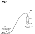
- an ultrasonic closing machine 300 in this embodiment includes an ultrasonic signal transmitter 310, an ultrasonic oscillator 320, a horn 330, and a closing tool 400.
- the ultrasonic signal transmitter 310 transmits electric ultrasonic signals.
- the ultrasonic oscillator 320 converts electric ultrasonic signals supplied from the ultrasonic signal transmitter 310 to mechanical ultrasonic vibration.
- the horn 330 amplifies an amplitude of the ultrasonic vibration supplied from the ultrasonic oscillator 220.
- the closing tool 400 is vibrated at a frequency of about 20 to 40 kHz by the ultrasonic vibration supplied from the horn 330.
- closing is carried out in an identical mode at both end surfaces of the green honeycomb molded body 70 having the inlet-side octagonal cells 70Octin and the outlet-side quadrangular cells 70Sout.
- a closing tool for closing an upper surface 71 a located on an exhaust gas supply side (inlet side) when the green honeycomb molded body 70 is applied to a particulate-matter-removing filter such as a diesel particulate filter after firing will be described.
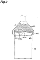
- a closing tool 400 in this embodiment includes a closing surface 401 a for performing closing of the green honeycomb molded body 70; and a support socket 450 in which the end of the green honeycomb molded body 70 is fitted.
- a plurality of closing projections 410a for welding partition walls 70W to each other and closing the outlet-side quadrangular cells 70Sout are provided by being arranged at positions corresponding to the inlet-side octagonal cells 70Octin and inserted respectively into the inlet-side octagonal cells 70Octin.
- the support socket 450 is formed of a cylindrical concave corresponding to the diameter of the green honeycomb molded body 70 to be closed.
- An inclined surface 451 is provided on the inner periphery of the support socket 450 in such a manner that the inner diameter of the support socket 450 increases with an increase in distance from the closing surface 401a to facilitate the insertion of the end of the green honeycomb molded body 70 into the support socket 450.
- the closing tool 400 in this embodiment includes closing projections 410c in a closing surface 401c of a closing tool 40 that is identical to that in the first embodiment.
- the closing projections 410c include a quadrangular pyramid-shaped base 416 and a conical tip 412.
- the quadrangular pyramid-shaped base 416 is located at a base of the closing projections 410c and is projected from the closing surface 401c.
- the quadrangular pyramid-shaped base 416 has a square cone platform shape in which a quadrangular pyramid reduced similarly from a quadrangular pyramid having a larger apex angle than the conical tip 412 is removed.
- the conical tip 412 is located at a position that is a tip of the closing projections 410c and above the quadrangular pyramid-shaped base 416.
- the conical tip 412 has a conical shape having a bottom surface having a size corresponding to the upper surface of the quadrangular pyramid-shaped base 416.
- the apex angle of the conical tip 412 is smaller than the apex angle defined by lateral edges of the square cone platform of the quadrangular pyramid-shaped base 416.
- the quadrangular pyramid-shaped base 416 includes a quadrangular pyramid side surface 417 that is a side surface of the square cone platform; and a roundness chamfering lateral edge 415 on the lateral edge of the square cone platform.
- roundness chamfering lateral edge 415 roundness chamfering has been conducted at a prescribed curvature for each lateral edge of the square cone platform.
- the valley between the quadrangular pyramid-shaped bases 416 in adjacent closing projections 410c includes a roundness chamfering valley 414 that is a concave formed by roundness chamfering at a prescribed curvature.
- apexes of conical tips 412 are arranged respectively at positions corresponding to the plurality of inlet-side octagonal cells 700ctin in the green honeycomb molded body 70.
- each of the closing projections 410c the roundness chamfering lateral edge 415 of the quadrangular pyramid-shaped base 416 is arranged in a direction that abuts against the partition wall 70W
- the size of each of the quadrangular pyramid-shaped bases 416 is a size such that a length that the roundness chamfering lateral edge 415 projects on the closing surface 401 c from just above the closing surface 401 c corresponds to a length between the center of the inlet-side octagonal cells 70Octin and the center of the outlet-side quadrangular cells 70Sout in the green honeycomb molded body 70.
- a closing tool 400 that has a closing surface 401c with closing projections 410c arranged at positions corresponding to the outlet-side quadrangular cells 70Sout is used as the closing tool 400 for closing the lower surface 71b functioning as an exhaust gas discharge side (an outlet side).
- the step of closing the green honeycomb molded body 70 in this embodiment will be described below.
- a particulate-matter-removing filter such as a diesel particulate filter after firing
- the step of closing the upper surface 71 a functioning as an exhaust gas supply side (an inlet side) will be described.
- the end on the upper surface 71a side of the green honeycomb molded body 70 is inserted into the support socket 450 in the closing tool 400 in the ultrasonic closing machine 300.
- the closing tool 400 is vibrated by ultrasonic vibration from the horn 330.
- the tip of the closing projections 410c in the closing surface 401c is inserted into the inlet-side octagonal cells 70Octin.
- the conical tip 412 of the closing projections 410c is inserted into the inlet-side octagonal cells 70Octin.
- the quadrangular pyramid-shaped base 416 of the closing projections 410c is inserted into the inlet-side octagonal cells 70Octin.
- the roundness chamfering lateral edges 415 in the quadrangular pyramid-shaped base 416 each abut against the partition walls 70W.
- the partition walls 70W are liquefied and pressed so as to close the outlet-side quadrangular cells 70Sout into which the closing projections 410c, that are located at the center of four inlet-side octagonal cells 70Octin into which the closing projections 410c have respectively been inserted, have not been inserted.
- the green honeycomb molded body 70 is applied to a particulate-matter-removing filter such as a diesel particulate filter after firing, for the step of closing the lower surface 71b functioning as the exhaust gas discharge side (outlet side), as illustrated in Fig. 12 , the end on the lower surface 71b side of the green honeycomb molded body 70 is inserted into the support socket 450 in the closing tool 400 in the ultrasonic closing machine 300.
- the closing tool 400 is vibrated by ultrasonic vibration from the horn 330.
- the tip of the closing projections 410c in the closing surface 401c is inserted into the outlet-side quadrangular cells 70Sout.
- the conical tip 412 in the closing projections 410c is inserted into the outlet-side quadrangular cells 70Sout.
- the quadrangular pyramid-shaped base 416 in the closing projections 410c is inserted into the outlet-side quadrangular cells 70Sout, as illustrated in Fig. 15 .
- Each of the roundness chamfering lateral edges 415 in the quadrangular pyramid-shaped base 416 is abutted against the partition walls 70W.
- the partition walls 70W are liquefied and each is pressed so as to close the inlet-side octagonal cells 70Octin into which the closing projections 410c have not been inserted and that are located at the center of the four outlet-side quadrangular cells 70Sout into which the closing projections 410c have been inserted.
- the partition walls 70W that have been pressed from four directions while being liquefied by the roundness chamfering lateral edge 415 and the quadrangular pyramid side surface 417 in the quadrangular pyramid-shaped base 416 are integrally welded to each other.
- the end of the welded partition walls 70W is abutted against the roundness chamfering valley 414 in the closing surface 401 c, and a round partition wall joined end 73 is formed in such a state that roundness chamfering corresponding to the shape of the roundness chamfering valley 414 has been conducted, thereby completing closing.
- one inlet-side octagonal cell 70Octin that is surrounded by four outlet-side quadrangular cells 70Sout respectively adjoining the periphery of one inlet-side octagonal cell 70Octin with the partition walls 70W provided between is closed.
- a plurality of inlet-side octagonal cells 70Octin and a plurality of outlet-side quadrangular cells 70Sout that have been mutually partitioned by partition walls 70W are open in an upper surface 71a and a lower surface 71b of a columnar body.
- the inlet-side octagonal cells 70Octin or the outlet-side quadrangular cells 70Sout are closed by joining together the partition walls 70W in the green honeycomb molded body 70, that become a honeycomb structure by firing, at the upper surface 71a and the lower surface 71b.
- the cells are closed by joining the partition walls (cell walls) 70W together, there is no need to use closing pastes such as in conventional methods. Further, since the cells are closed by welding the cell walls together, when the honeycomb structure is used in a particulate-matter-removing filter such as a diesel particulate filter, the inlet and the outlet of exhaust gas flow passages in the end surface can be made larger than an opening area of the through-holes, whereby turbulence of the flow of the exhaust gas at the end surface on the exhaust gas supply side can be reduced and pressure loss can be reduced. As illustrated in Fig.
- the green honeycomb molded body 70 with a part of through-holes to be closed has, in the upper surface 71 a or the lower surface 71b, one inlet-side octagonal cell 70Octin and four outlet-side quadrangular cells 70Sout that have a smaller opening area than the inlet-side octagonal cell 70Octin adjoining around the one inlet-side octagonal cell 70Octin through the partition walls 70W.
- the honeycomb structure when the honeycomb structure is applied to a particulate-matter-removing filter such as a diesel particulate filter, in the particulate-matter-removing filter, when the inlet-side octagonal cells 70Octin having a large opening area are opened while closing the outlet-side quadrangular cells 70Sout having a small opening area on the inlet side, and when the outlet-side quadrangular cells 70Sout having a small opening area are opened while closing the inlet-side octagonal cells 70Octin having a large opening area on the outlet side, the inlet side becomes wide and the pressure loss in such a state that soot is deposited can be reduced.
- a particulate-matter-removing filter such as a diesel particulate filter
- the through-holes having a large opening area are inlet-side octagonal cells 70Octin and the through-holes that adjoin around the inlet-side octagonal cells 70Octin and have a small opening area are outlet-side quadrangular cells 70Sout. Therefore, when the outlet-side quadrangular cell 70Sout adjoins every other side of the inlet-side octagonal cell 70Octin, through-holes having a different size can be arranged in the upper surface 71a or the lower surface 71 b.
- the outlet-side quadrangular cells 70Sout are closed, and, in the lower surface 71b, the inlet-side octagonal cells 700ctin are closed.
- a particulate-matter-removing filter such as a diesel particulate filter
- the inlet-side octagonal cells 70Octin having a large opening area are opened while closing the outlet-side quadrangular cells 70Sout having a small opening area on the inlet side
- the outlet-side quadrangular cells 70Sout having a small opening area are opened while closing the inlet-side octagonal cells 70Octin having a large opening area on the outlet side
- the inlet side becomes wide and the pressure loss in such a state that soot is deposited can be reduced.
- the outlet-side quadrangular cells 70Sout are closed by inserting closing projections 410c in the closing tool 400 including any shape of a quadrangular pyramid and a quadrangular pyramid platform into the inlet-side octagonal cells 700ctin while allowing the roundness chamfering lateral edge 415 to abut against each of the partition walls 70W that adjoin the roundness chamfering lateral edge 415.
- the outlet-side quadrangular cells 70Sout can be closed easily and reliably.
- the inlet-side octagonal cells 700ctin are closed by inserting closing projections 410c in the closing tool 400 including any shape of a quadrangular pyramid and a quadrangular pyramid platform into through-holes, respectively, in the outlet-side quadrangular cells 70Sout while allowing the roundness chamfering lateral edge 415 of the closing projections 410c to abut against the partition walls 70W adjacent to the inlet-side octagonal cells 70Octin.
- the inlet-side octagonal cells 70Octin can be closed easily and reliably.
- a green honeycomb molded body 70 in this embodiment is, for example, a cylindrical body that has an upper surface 71 a, a lower surface 71 b, and a side surface 71 c and in which a plurality of inlet-side rounded quadrangular cells 70SRin that are rounded quadrangular through-holes with the corner of the quadrangle being rounded, and outlet-side quadrangular cells 70Sout that are quadrangular through-holes that are the same as those in the first embodiment are open in the upper surface 71 a and the lower surface 71b.
- the inlet-side rounded quadrangular cells 70SRin and the outlet-side quadrangular cells 70Sout extend substantially parallel from the upper surface 71 a to the lower surface 71b along the side surface 71 c.
- the green honeycomb molded body 70 is an unfired molded body that, by firing later, becomes a porous ceramic and is identical in material and production method to that in the first embodiment except for the inlet-side rounded quadrangular cells 70SRin.
- the length of the direction in which the inlet-side rounded quadrangular cells 70SRin and the outlet-side quadrangular cells 70Sout in the green honeycomb molded body 70 extend is not particularly limited but may be, for example, 40 to 400 mm.
- inlet-side rounded quadrangular cells 70SRin having a large opening area and outlet-side quadrangular cells 70Sout having a smaller opening area than the inlet-side rounded quadrangular cells 70SRin are partitioned by partition walls 70W.
- the inlet-side rounded quadrangular cells 70SRin have a rounded quadrangular shape in which the corner of the quadrangle has been roundly chamfered.
- Four outlet-side quadrangular cells 70Sout adjoin around one inlet-side rounded quadrangular cell 70SRin through respective four partition walls 70W that partition the four sides of the inlet-side rounded quadrangular cell 70SRin.
- inlet-side rounded quadrangular cells 70SRin adjoin around one outlet-side quadrangular cell 70Sout through respective four partition walls 70W that partition each side of the outlet-side quadrangular cells 70Sout.
- the inlet-side rounded quadrangular cells 70SRin may not be one in which the corner of a square has been rounded.
- the inlet-side rounded quadrangular cells 70SRin may have a round quadrangular shape that is elongate in one direction.
- the inlet-side rounded quadrangular cells 70SRin may have a round quadrangular shape in which the corner of a parallelogram has been rounded.
- the step of closing the green honeycomb molded body 70 in this embodiment will be described below.
- the inlet-side rounded quadrangular cells 70SRin and the outlet-side quadrangular cells 70Sout are closed using a closing tool 400 that is the same as that in the above-described first embodiment.
- the step of closing the upper surface 71 a functioning as an exhaust gas supply side (an inlet side) in the case where the green honeycomb molded body 70 is applied to a particulate-matter-removing filter such as a diesel particulate filter after firing will be described.
- the end on the upper surface 71a side of the green honeycomb molded body 70 is inserted into the support socket 450 in the closing tool 400 in the ultrasonic closing machine 300.
- the closing tool 400 is vibrated by ultrasonic vibration from the horn 330.
- the tip of the closing projections 410c in the closing surface 401c is inserted into the inlet-side rounded quadrangular cells 70SRin.
- the conical tip 412 of the closing projections 410c is inserted into the inlet-side rounded quadrangular cells 70SRin.
- the quadrangular pyramid-shaped base 416 in the closing projections 410c are inserted into the inlet-side rounded quadrangular cells 70SRin.
- the roundness chamfering lateral edges 415 in the quadrangular pyramid-shaped base 416 each abut against the partition walls 70W.
- the partition walls 70W are liquefied and pressed so as to close the outlet-side quadrangular cells 70Sout into which the closing projections 410c have not been inserted that are located at the center of four inlet-side rounded quadrangular cells 70SRin into which the closing projections 410c have respectively been inserted.
- the green honeycomb molded body 70 is applied to a particulate-matter-removing filter such as a diesel particulate filter after firing, for the step of closing the lower surface 71b functioning as the exhaust gas discharge side (outlet side), as illustrated in Fig. 12 , the end on the lower surface 71b side of the green honeycomb molded body 70 is inserted into the support socket 450 in the closing tool 400 in the ultrasonic closing machine 300.
- the closing tool 400 is vibrated by ultrasonic vibration from the horn 330.
- the tip of the closing projections 410c in the closing surface 401c are inserted into the outlet-side quadrangular cells 70Sout.
- the conical tip 412 of the closing projections 410c is inserted into the outlet-side quadrangular cells 70Sout.
- the quadrangular pyramid-shaped base 416 in the closing projections 410c is inserted into the outlet-side quadrangular cells 70Sout, as illustrated in Fig. 24 .
- Each of the roundness chamfering lateral edges 415 in the quadrangular pyramid-shaped base 416 is abutted against the partition walls 70W.
- the partition walls 70W are liquefied and each are pressed so as to close the inlet-side rounded quadrangular cells 70SRin into which the closing projections 410c have not been inserted and that are located at the center of the four outlet-side quadrangular cells 70Sout into which the closing projections 410c have been inserted.
- the through-holes having a large opening area are inlet-side rounded quadrangular cells 70SRin and the through-holes that adjoin around the inlet-side rounded quadrangular cells 70SRin and have a small opening area are outlet-side quadrangular cells 70Sout. Therefore, when the outlet-side quadrangular cell 70Sout adjoins every other side of the inlet-side rounded quadrangular cells 70SRin, through-holes having a different size can be arranged in the upper surface 71 a or the lower surface 71b.
- the present invention is not limited to the above embodiments, and various modifications are possible.
- the closed green honeycomb molded body 70 has been closed by welding the partition walls 70W together through the application of ultrasonic waves.
- the closed green honeycomb molded body 70 is not limited to this embodiment.
- the closed green honeycomb molded body 70 includes a closed green honeycomb molded body 70 that has been closed by contact bonding between partition walls 70W without the application of ultrasonic waves.
- the closed green honeycomb molded body 70 includes a closed green honeycomb molded body 70 that has been closed by contact bonding between partition walls 70W through the application of vibration at a lower frequency than ultrasonic waves, for example, at 1 kHz or less.
- the method for producing a honeycomb structure according to one aspect of the present invention can provide a production method in which a sealing paste is not needed and which can simply close the end of the honeycomb structure, and a honeycomb structure produced by the method.
Landscapes
- Engineering & Computer Science (AREA)
- Chemical & Material Sciences (AREA)
- Ceramic Engineering (AREA)
- Mechanical Engineering (AREA)
- Manufacturing & Machinery (AREA)
- Chemical Kinetics & Catalysis (AREA)
- Structural Engineering (AREA)
- Filtering Materials (AREA)
- Physics & Mathematics (AREA)
- Geometry (AREA)
- Porous Artificial Stone Or Porous Ceramic Products (AREA)
- Devices For Post-Treatments, Processing, Supply, Discharge, And Other Processes (AREA)
- Filtering Of Dispersed Particles In Gases (AREA)
Abstract
Description
- An aspect of the present invention relates to a method for producing honeycomb structures and also relates to a method for producing honeycomb structures in which a green honeycomb molded body is fired to produce a honeycomb structure.
- For example, honeycomb hole structures made of ceramic and having a plurality of through-holes of a cross-section polygonal shape are conventionally known. Such honeycomb structures are used, for example, in particulate-matter-removing filters such as diesel particulate filters. In a production step of such honeycomb structures, a ceramic raw material powder is formed by extruding to produce a green honeycomb molded body. A part of through-holes in this green honeycomb molded body are closed at an end surface. A honeycomb structure is produced by firing the green honeycomb molded body with closed through-holes. Patent Literature 1 discloses a method for producing such honeycomb structures. In Patent Literature 1, a sealing material is pressed with a piston against one end of a honeycomb structure placed within a cylinder to supply the sealing material to the end of through-holes in the honeycomb structure and to close the through-holes.
- PTL 1: Japanese Examined Patent Publication No.
S63-24731 - However, in the method in the above Patent Literature 1, sealing materials such as sealing pastes are necessary. Further, Patent Literature 1 has the problem that it requires a very troublesome step, for example, applying a sealing mask to an end surface and opening a hole at a place to be closed in the mask.
- In the technical field, production methods in which sealing pastes are not needed and which can simply close the end of a honeycomb structure, and honeycomb structures obtained by those production methods have been desired.
- One aspect of the present invention is a method for producing a honeycomb structure, the method comprising a closing step of joining together partition walls of a green honeycomb molded body in which a plurality of through-holes partitioned by partition walls are open to each other at the end surface of a columnar body to close a part of the through-holes, wherein the green honeycomb molded body in which a part of the through-holes are closed at the closing step includes, at the end surface, one first through-hole and four second through-holes that have a smaller opening area than the first through hole and that adjoin around the first through-hole with the partition wall provided between the first through-hole and the second through-holes.
- With this construction, it is unnecessary to use sealing pastes, such as in conventional methods, and the end of honeycomb structures can be simply closed. Further, since cells are closed by welding cell walls together, when the honeycomb structure is used in diesel particulate filters, turbulence of flow of exhaust gases at the end surface on the exhaust gas supply side is reduced and pressure loss can be reduced.
- In this case, the first through-hole may be octagonal, and the second through-holes may be quadrangular.
- According to this construction, the first through-hole is octagonal, and the second through-holes are quadrangular. For this reason, for example, when the quadrangular through-holes adjoin every other side of the octagonal through-hole, through-holes having a different size can be arranged in the end surface.
- Further, the first through-hole may have a round quadrangular shape with a corner of the quadrangle being rounded, and the second through-hole may have a quadrangular shape.
- According to this construction, the first through-hole has a round quadrangular shape with the corner of the quadrangle being rounded, and the second through-hole has a quadrangular shape. For this reason, for example, when the quadrangular through-hole adjoins each of the four sides of the round quadrangular through-hole, through-holes having a different size can be arranged in the end surface.
- Further, at the closing step, the second through-hole can be closed at one of the end surfaces and the first through-hole can be closed at the other end surface.
- According to this construction, at the closing step, the second through-holes are closed at one of the end surfaces, and the first through-holes are closed at the other end surface. For this reason, for example, when the honeycomb structure is applied to a particulate-matter-removing filter such as a diesel particulate filter, when first through-holes having a large opening area are open while closing the second through-holes having a small opening area on an inlet side of the particulate-matter-removing filter, and the second through-holes having a small opening area are open while closing the first through-holes having a large opening area on an outlet side, the inlet side becomes wide and pressure loss in a state in which soot is deposited can be reduced.
- Further, at the closing step, by inserting a closing tool into a part of a plurality of through-holes in the green honeycomb molded body, partition walls are joined together at the end surface and the through-holes can be closed.
- According to this construction, at the closing step, by inserting a closing tool into a part of the plurality of through-holes in the green honeycomb molded body, the partition walls are joined together at the end surface to close the through-holes. Thus, the closing of the through-holes can very easily be carried out.
- In this case, at the closing step, in closing the second through-holes, by inserting a closing tool including any one shape of a quadrangular pyramid and a quadrangular pyramid platform into the first through-hole while allowing the lateral edge of the closing tool to abut against each of the partition walls that adjoin the second through-holes, the second through-holes can be closed.
- According to this construction, at the closing step, in closing the second through-holes, by inserting a closing tool including any one shape of a quadrangular pyramid and a quadrangular pyramid platform into the first through-hole while allowing the lateral edge of the closing tool to abut against each of the partition walls that adjoin the second through-holes, the second through-holes are closed. Thus, the second through-holes can easily and reliably be closed.
- Further, at the closing step, in closing the first through-hole, by inserting a closing tool including any one shape of a quadrangular pyramid and a quadrangular pyramid platform into each of the second through-holes while allowing the lateral edge of the closing tool to abut against the partition walls that adjoin the first through-hole, the first through-hole can be closed.
- According to this construction, at the closing step, in closing the first through-hole, by inserting a closing tool including any one shape of a quadrangular pyramid and a quadrangular pyramid platform into each of the second through-holes while allowing the lateral edge of the closing tool to abut against the partition walls that adjoin the first through-hole, the first through-hole is closed. Thus, the first through-hole can easily and reliably be closed.
- The method for producing a honeycomb structure according to one aspect of the present invention can provide a production method in which a sealing paste is not needed and which can simply close the end of the honeycomb structure, and a honeycomb structure produced by the method.
-
-
Fig. 1(a) is a perspective view of a green honeycomb molded body according to a first embodiment before closing. -
Fig. 1(b) is a partial enlarged view ofFig. 1(a) . -
Fig. 2 is a perspective view of a closing apparatus for a green honeycomb molded body according to a first embodiment. -
Fig. 3 is a partial cross-sectional view of a closing tool for an inlet side of a green honeycomb molded body according to a first embodiment. -
Fig. 4 is an enlarged perspective view of a portion A ofFig. 3 . -
Fig. 5 is an enlarged plan view of a portion A ofFig. 3 . -
Fig. 6 is a partial cross-sectional view illustrating an initial state of a closing step on an inlet side of a green honeycomb molded body according to a first embodiment. -
Fig. 7 is a cross-sectional view taken along line VII-VII ofFig. 6 . -
Fig. 8 is a partial cross-sectional view illustrating a middle state of a closing step inFig. 6 . -
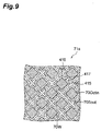
Fig. 9 is a cross-sectional view taken along line IX-IX ofFig. 8 . -
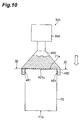
Fig. 10 is a partial cross-sectional view illustrating a final state of a closing step inFig. 6 . -
Fig. 11 is a cross-sectional view taken along line XI-XI ofFig. 10 . -
Fig. 12 is a partial cross-sectional view illustrating an initial state of a closing step on an outlet side of a green honeycomb molded body according to a first embodiment. -
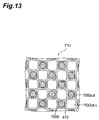
Fig. 13 is a cross-sectional view taken along line XIII-XIII ofFig. 12 . -
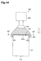
Fig. 14 is a partial cross-sectional view illustrating a middle state of a closing step inFig. 12 . -
Fig. 15 is a cross-sectional view taken along line XV-XV ofFig. 14 . -
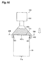
Fig. 16 is a partial cross-sectional view illustrating a final state of a closing step inFig. 12 . -
Fig. 17 is a cross-sectional view taken on line XVII-XVII ofFig. 16 . -
Fig. 18(a) is a diagram illustrating flow of gas that passes through conventional closed cells. -
Fig. 18(b) is a diagram illustrating flow of gas that passes through closed cells according to an embodiment of the present invention. -
Fig. 19(a) is a perspective view of a green honeycomb molded body according to a first embodiment before closing. -
Fig. 19(b) is a partial enlarged view ofFig. 19(a) . -
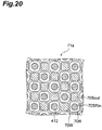
Fig. 20 is a cross-sectional view corresponding to a cross section taken along line VII-VII ofFig. 6 in a closing step on an inlet side in a second embodiment. -
Fig. 21 is a cross-sectional view corresponding to a cross section taken along line IX-IX ofFig. 8 in a closing step on an inlet side according to a second embodiment. -
Fig. 22 is a cross-sectional view corresponding to a cross section taken along line XI-XI ofFig. 10 in a closing step on an inlet side according to a second embodiment. -
Fig. 23 is a cross-sectional view corresponding to a cross section taken along line XIII-XIII ofFig. 12 in a closing step on an outlet side according to a second embodiment. -
Fig. 24 is a cross-sectional view corresponding to a cross section taken along line XV-XV ofFig. 14 in a closing step on an outlet side according to a second embodiment. -
Fig. 25 is a cross-sectional view corresponding to a cross section taken along line XVII-XVII ofFig. 16 in a closing step on an outlet side according to a second embodiment. - Embodiments of the present invention will be described in detail with reference to the drawings.
- First, a green honeycomb molded body that is an object to be machined in the first embodiment of the present invention will be described. As illustrated in
Fig. 1(a) , a green honeycomb moldedbody 70 according to this embodiment is, for example, a cylindrical body that has anupper surface 71a, alower surface 71 b, and aside surface 71c, and in which a plurality of inlet-side octagonal cells 700ctin that are octagonal through-holes and a plurality of outlet-side quadrangular cells 70Sout that are quadrangular through-holes are open in theupper surface 71 a and thelower surface 71b. The inlet-side octagonal cells 700ctin and the outlet-side quadrangular cells 70Sout extend substantially parallel from theupper surface 71a to thelower surface 71 b along aside surface 71 c. The green honeycomb moldedbody 70 is an unfired molded body that, by firing later, becomes a porous ceramic. Further, the length of the direction in which the inlet-side octagonal cells 700ctin and the outlet-side quadrangular cells 70Sout in the green honeycomb moldedbody 70 extend is not particularly limited but may be, for example, 40 to 400 mm. The outer diameter of the green honeycomb moldedbody 70 is also not particularly limited but may be, for example, 10 to 360 mm. - As illustrated in
Fig. 1(b) , in theupper surface 71a or thelower surface 71b, the inlet-side octagonal cells 70Octin having a large opening area and the outlet-side quadrangular cells 70Sout having a smaller opening area than the inlet-side octagonal cells 70Octin are partitioned bypartition walls 70W The inlet-side octagonal cells 70Octin have an octagonal shape in which the corner portion of the quadrilateral shape is further cut by a straight side. Four outlet-side quadrangular cells 70Sout are respectively adjacent to portions around one inlet-side octagonal cell 70Octin through fourpartition walls 70W that partition four sides except for the corner portion of the inlet-side octagonal cells 70Octin. Four inlet-side octagonal cells 70Octin are respectively adjacent to portions around one outlet-side quadrangular cell 70Sout through fourpartition walls 70W that partition respective sides of the outlet-side quadrangular cells 70Sout. The inlet-side octagonal cells 70Octin may not have a regular octahedral shape, and the outlet-side quadrangular cells 70Sout may not have a regular square shape. For example, the inlet-side octagonal cells 70Octin may have an octagonal shape that is long in one direction, and the outlet-side quadrangular cells 70Sout may have a rectangular shape. Further, the inlet-side octagonal cells 70Octin may have an octagonal shape in which the corner portion of a parallelogram shape is cut by a straight side, and the outlet-side quadrangular cells 70Sout may have a parallelogram shape. - It should be noted that the outer shape of the green honeycomb molded
body 70 is not limited to a cylindrical shape and may be an elliptical column, an angular column (for example, a regular polygonal column such as a triangular column, a square column, a hexagonal column, or an octagonal column; or a triangular column, a square column, a hexagonal column, or an octagonal column other than the regular polygonal column) or the like. In this embodiment, a cylindrical shape of the green honeycomb moldedbody 70 will be described. - Such a green honeycomb molded
body 70 is produced by extruding a ceramic composition with an extruder. In this case, in order to prepare a ceramic composition, a powder of an inorganic compound source which is a ceramic raw material, an organic binder, a solvent, and, if necessary, additives to be added are provided. - Inorganic compound source powders include powders containing two or more types of powders selected from the group consisting of aluminum source powders, magnesium source powders, silicon source powders, and titanium source powders; or powders containing one or more types of powders selected from any one of silicon carbide source powders, silicon nitride source powders, and aluminum nitride source powders. In order to improve heat resistance and mechanical strength of products, one or more types of any one of carbon source powders, zirconium source powders, molybdenum source powers, and calcium source powders may be added to the inorganic compound source powder. Including aluminum source powders, magnesium source powders, titanium source powders, and silicon source powders can improve heat resistance. Examples of organic binders include celluloses such as methylcellulose, carboxylmethylcellulose, hydroxyalkylmethylcellulose, and sodium carboxylmethylcellulose; alcohols such as polyvinyl alcohol; and lignin sulfonic acid salts. Additives include, for example, pore forming agents, lubricating agents and plasticizers, dispersing agents, and solvents.
- The green honeycomb molded body according to this embodiment is produced by mixing the prepared raw materials with a kneader or the like to obtain a raw material mixture, and extruding the raw material mixture thus obtained through an extruder having an outlet opening corresponding to the sectional shape of the
partition walls 70W. - An ultrasonic closing machine in this embodiment will be described below. As illustrated in
Fig. 2 , anultrasonic closing machine 300 in this embodiment includes anultrasonic signal transmitter 310, anultrasonic oscillator 320, ahorn 330, and aclosing tool 400. As with the above ultrasonic cutter 200, theultrasonic signal transmitter 310 transmits electric ultrasonic signals. Theultrasonic oscillator 320 converts electric ultrasonic signals supplied from theultrasonic signal transmitter 310 to mechanical ultrasonic vibration. Thehorn 330 amplifies an amplitude of the ultrasonic vibration supplied from the ultrasonic oscillator 220. Theclosing tool 400 is vibrated at a frequency of about 20 to 40 kHz by the ultrasonic vibration supplied from thehorn 330. - The closing tool in this embodiment will be described below. In this embodiment, closing is carried out in an identical mode at both end surfaces of the green honeycomb molded
body 70 having the inlet-side octagonal cells 70Octin and the outlet-side quadrangular cells 70Sout. First, a closing tool for closing anupper surface 71 a located on an exhaust gas supply side (inlet side) when the green honeycomb moldedbody 70 is applied to a particulate-matter-removing filter such as a diesel particulate filter after firing will be described. - As illustrated in
Fig. 3 , aclosing tool 400 in this embodiment includes a closing surface 401 a for performing closing of the green honeycomb moldedbody 70; and asupport socket 450 in which the end of the green honeycomb moldedbody 70 is fitted. In the closing surface 401a, a plurality of closing projections 410a for weldingpartition walls 70W to each other and closing the outlet-side quadrangular cells 70Sout are provided by being arranged at positions corresponding to the inlet-side octagonal cells 70Octin and inserted respectively into the inlet-side octagonal cells 70Octin. Thesupport socket 450 is formed of a cylindrical concave corresponding to the diameter of the green honeycomb moldedbody 70 to be closed. Aninclined surface 451 is provided on the inner periphery of thesupport socket 450 in such a manner that the inner diameter of thesupport socket 450 increases with an increase in distance from the closing surface 401a to facilitate the insertion of the end of the green honeycomb moldedbody 70 into thesupport socket 450. - As illustrated in
Figs. 4 and5 that are enlarged views of a site corresponding to a portion A in the above-describedFig. 3 , theclosing tool 400 in this embodiment includes closingprojections 410c in aclosing surface 401c of a closing tool 40 that is identical to that in the first embodiment. Theclosing projections 410c include a quadrangular pyramid-shapedbase 416 and aconical tip 412. The quadrangular pyramid-shapedbase 416 is located at a base of theclosing projections 410c and is projected from theclosing surface 401c. The quadrangular pyramid-shapedbase 416 has a square cone platform shape in which a quadrangular pyramid reduced similarly from a quadrangular pyramid having a larger apex angle than theconical tip 412 is removed. Theconical tip 412 is located at a position that is a tip of theclosing projections 410c and above the quadrangular pyramid-shapedbase 416. Theconical tip 412 has a conical shape having a bottom surface having a size corresponding to the upper surface of the quadrangular pyramid-shapedbase 416. The apex angle of theconical tip 412 is smaller than the apex angle defined by lateral edges of the square cone platform of the quadrangular pyramid-shapedbase 416. - The quadrangular pyramid-shaped
base 416 includes a quadrangularpyramid side surface 417 that is a side surface of the square cone platform; and a roundness chamferinglateral edge 415 on the lateral edge of the square cone platform. In the roundness chamferinglateral edge 415, roundness chamfering has been conducted at a prescribed curvature for each lateral edge of the square cone platform. Further, the valley between the quadrangular pyramid-shapedbases 416 inadjacent closing projections 410c includes aroundness chamfering valley 414 that is a concave formed by roundness chamfering at a prescribed curvature. - As illustrated in
Fig. 5 , in each of theclosing projections 410c, apexes ofconical tips 412 are arranged respectively at positions corresponding to the plurality of inlet-side octagonal cells 700ctin in the green honeycomb moldedbody 70. Further, in each of theclosing projections 410c, the roundness chamferinglateral edge 415 of the quadrangular pyramid-shapedbase 416 is arranged in a direction that abuts against thepartition wall 70W The size of each of the quadrangular pyramid-shapedbases 416 is a size such that a length that the roundness chamferinglateral edge 415 projects on theclosing surface 401 c from just above theclosing surface 401 c corresponds to a length between the center of the inlet-side octagonal cells 70Octin and the center of the outlet-side quadrangular cells 70Sout in the green honeycomb moldedbody 70. - It should be noted that when the green honeycomb molded
body 70 is applied to a particulate-matter-removing filter such as a diesel particulate filter after firing, as with theupper surface 71 a, aclosing tool 400 that has aclosing surface 401c withclosing projections 410c arranged at positions corresponding to the outlet-side quadrangular cells 70Sout is used as theclosing tool 400 for closing thelower surface 71b functioning as an exhaust gas discharge side (an outlet side). - The step of closing the green honeycomb molded
body 70 in this embodiment will be described below. First, in the case where the green honeycomb moldedbody 70 is applied to a particulate-matter-removing filter such as a diesel particulate filter after firing, the step of closing theupper surface 71 a functioning as an exhaust gas supply side (an inlet side) will be described. - As illustrated in
Fig. 6 , the end on theupper surface 71a side of the green honeycomb moldedbody 70 is inserted into thesupport socket 450 in theclosing tool 400 in theultrasonic closing machine 300. Theclosing tool 400 is vibrated by ultrasonic vibration from thehorn 330. As illustrated inFig. 7 , the tip of theclosing projections 410c in theclosing surface 401c is inserted into the inlet-side octagonal cells 70Octin. Theconical tip 412 of theclosing projections 410c is inserted into the inlet-side octagonal cells 70Octin. - As illustrated in
Fig. 8 , when theclosing projections 410c are further inserted into the inlet-side octagonal cells 70Octin, as illustrated inFig. 9 , the quadrangular pyramid-shapedbase 416 of theclosing projections 410c is inserted into the inlet-side octagonal cells 70Octin. The roundness chamferinglateral edges 415 in the quadrangular pyramid-shapedbase 416 each abut against thepartition walls 70W. Since theclosing projections 410c are vibrated by ultrasonic vibration, thepartition walls 70W are liquefied and pressed so as to close the outlet-side quadrangular cells 70Sout into which theclosing projections 410c, that are located at the center of four inlet-side octagonal cells 70Octin into which theclosing projections 410c have respectively been inserted, have not been inserted. - As illustrated in
Fig. 10 , when theclosing projections 410c are further inserted into the inlet-side octagonal cells 70Octin, as illustrated inFig. 11 , thepartition walls 70W that have been pressed from four directions while being liquefied by the roundness chamferinglateral edge 415 and the quadrangularpyramid side surface 417 in the quadrangular pyramid-shapedbase 416 are integrally welded to each other. The end of the weldedpartition walls 70W is abutted against theroundness chamfering valley 414 in theclosing surface 401c, and a round partition wall joinedend 73 is formed in such a state that roundness chamfering corresponding to the shape of theroundness chamfering valley 414 has been conducted, thereby completing closing. Thus, in theupper surface 71 a functioning as the exhaust gas supply side (inlet side), one outlet-side quadrangular cell 70Sout that is surrounded by four inlet-side octagonal cells 70Octin respectively adjoining the periphery of one outlet-side quadrangular cell 70Sout with thepartition walls 70W provided between is closed. - On the other hand, when the green honeycomb molded
body 70 is applied to a particulate-matter-removing filter such as a diesel particulate filter after firing, for the step of closing thelower surface 71b functioning as the exhaust gas discharge side (outlet side), as illustrated inFig. 12 , the end on thelower surface 71b side of the green honeycomb moldedbody 70 is inserted into thesupport socket 450 in theclosing tool 400 in theultrasonic closing machine 300. Theclosing tool 400 is vibrated by ultrasonic vibration from thehorn 330. The tip of theclosing projections 410c in theclosing surface 401c is inserted into the outlet-side quadrangular cells 70Sout. As illustrated inFig. 13 , theconical tip 412 in theclosing projections 410c is inserted into the outlet-side quadrangular cells 70Sout. - As illustrated in
Fig. 14 , when theclosing projections 410c are further inserted into the outlet-side quadrangular cells 70Sout, the quadrangular pyramid-shapedbase 416 in theclosing projections 410c is inserted into the outlet-side quadrangular cells 70Sout, as illustrated inFig. 15 . Each of the roundness chamferinglateral edges 415 in the quadrangular pyramid-shapedbase 416 is abutted against thepartition walls 70W. Since theclosing projections 410c are vibrated by ultrasonic vibration, thepartition walls 70W are liquefied and each is pressed so as to close the inlet-side octagonal cells 70Octin into which theclosing projections 410c have not been inserted and that are located at the center of the four outlet-side quadrangular cells 70Sout into which theclosing projections 410c have been inserted. - As illustrated in
Fig. 16 , when theclosing projections 410c are further inserted into the outlet-side quadrangular cells 70Sout, as illustrated inFig. 17 , thepartition walls 70W that have been pressed from four directions while being liquefied by the roundness chamferinglateral edge 415 and the quadrangularpyramid side surface 417 in the quadrangular pyramid-shapedbase 416 are integrally welded to each other. The end of the weldedpartition walls 70W is abutted against theroundness chamfering valley 414 in theclosing surface 401 c, and a round partition wall joinedend 73 is formed in such a state that roundness chamfering corresponding to the shape of theroundness chamfering valley 414 has been conducted, thereby completing closing. Thus, in thelower surface 71b functioning as the exhaust gas discharge side (outlet side), one inlet-side octagonal cell 70Octin that is surrounded by four outlet-side quadrangular cells 70Sout respectively adjoining the periphery of one inlet-side octagonal cell 70Octin with thepartition walls 70W provided between is closed. - In this embodiment, in the method for producing a honeycomb structure, a plurality of inlet-side octagonal cells 70Octin and a plurality of outlet-side quadrangular cells 70Sout that have been mutually partitioned by
partition walls 70W are open in anupper surface 71a and alower surface 71b of a columnar body. The inlet-side octagonal cells 70Octin or the outlet-side quadrangular cells 70Sout are closed by joining together thepartition walls 70W in the green honeycomb moldedbody 70, that become a honeycomb structure by firing, at theupper surface 71a and thelower surface 71b. Thereby, since the cells are closed by joining the partition walls (cell walls) 70W together, there is no need to use closing pastes such as in conventional methods. Further, since the cells are closed by welding the cell walls together, when the honeycomb structure is used in a particulate-matter-removing filter such as a diesel particulate filter, the inlet and the outlet of exhaust gas flow passages in the end surface can be made larger than an opening area of the through-holes, whereby turbulence of the flow of the exhaust gas at the end surface on the exhaust gas supply side can be reduced and pressure loss can be reduced. As illustrated inFig. 18(a) , when the outlet-side quadrangular cells 70Sout are closed with aconventional closing material 70P, there is a drawback that air resistance is large at theupper surface 71a functioning as the exhaust gas supply side (inlet side). On the other hand, as illustrated inFig. 18(b) , when the outlet-side quadrangular cells 70Sout are closed by the production method in this embodiment, since the inlet of the gas flow passage in theupper surface 71 a is large and the end of theclosed partition walls 70W is tapered, the air resistance can be reduced to a very high extent. - The green honeycomb molded
body 70 with a part of through-holes to be closed has, in theupper surface 71 a or thelower surface 71b, one inlet-side octagonal cell 70Octin and four outlet-side quadrangular cells 70Sout that have a smaller opening area than the inlet-side octagonal cell 70Octin adjoining around the one inlet-side octagonal cell 70Octin through thepartition walls 70W. Accordingly, for example, when the honeycomb structure is applied to a particulate-matter-removing filter such as a diesel particulate filter, in the particulate-matter-removing filter, when the inlet-side octagonal cells 70Octin having a large opening area are opened while closing the outlet-side quadrangular cells 70Sout having a small opening area on the inlet side, and when the outlet-side quadrangular cells 70Sout having a small opening area are opened while closing the inlet-side octagonal cells 70Octin having a large opening area on the outlet side, the inlet side becomes wide and the pressure loss in such a state that soot is deposited can be reduced. - Further, the through-holes having a large opening area are inlet-side octagonal cells 70Octin and the through-holes that adjoin around the inlet-side octagonal cells 70Octin and have a small opening area are outlet-side quadrangular cells 70Sout. Therefore, when the outlet-side quadrangular cell 70Sout adjoins every other side of the inlet-side octagonal cell 70Octin, through-holes having a different size can be arranged in the
upper surface 71a or thelower surface 71 b. - Further, in the
upper surface 71a, the outlet-side quadrangular cells 70Sout are closed, and, in thelower surface 71b, the inlet-side octagonal cells 700ctin are closed. Thus, for example, when the honeycomb structure is applied to a particulate-matter-removing filter such as a diesel particulate filter, in the particulate-matter-removing filter, when the inlet-side octagonal cells 70Octin having a large opening area are opened while closing the outlet-side quadrangular cells 70Sout having a small opening area on the inlet side, and when the outlet-side quadrangular cells 70Sout having a small opening area are opened while closing the inlet-side octagonal cells 70Octin having a large opening area on the outlet side, the inlet side becomes wide and the pressure loss in such a state that soot is deposited can be reduced. - When closing
projections 410c in theclosing tool 400 are inserted into the plurality of inlet-side octagonal cells 70Octin or outlet-side quadrangular cells 70Sout in the green honeycomb moldedbody 70, thepartition walls 70W are joined together at theupper surface 71a or thelower surface 71b and the cells are closed. Thus, the closing of the cells can very easily be carried out. - Further, in the closing of the outlet-side quadrangular cells 70Sout, the outlet-side quadrangular cells 70Sout are closed by inserting
closing projections 410c in theclosing tool 400 including any shape of a quadrangular pyramid and a quadrangular pyramid platform into the inlet-side octagonal cells 700ctin while allowing the roundness chamferinglateral edge 415 to abut against each of thepartition walls 70W that adjoin the roundness chamferinglateral edge 415. Thus, the outlet-side quadrangular cells 70Sout can be closed easily and reliably. - Further, in the closing of the inlet-side octagonal cells 70Octin, the inlet-side octagonal cells 700ctin are closed by inserting
closing projections 410c in theclosing tool 400 including any shape of a quadrangular pyramid and a quadrangular pyramid platform into through-holes, respectively, in the outlet-side quadrangular cells 70Sout while allowing the roundness chamferinglateral edge 415 of theclosing projections 410c to abut against thepartition walls 70W adjacent to the inlet-side octagonal cells 70Octin. Thus, the inlet-side octagonal cells 70Octin can be closed easily and reliably. - First, a green honeycomb molded body that is an object to be machined in the second embodiment of the present invention will be described. As illustrated in
Fig. 19(a) , a green honeycomb moldedbody 70 in this embodiment is, for example, a cylindrical body that has anupper surface 71 a, alower surface 71 b, and aside surface 71 c and in which a plurality of inlet-side rounded quadrangular cells 70SRin that are rounded quadrangular through-holes with the corner of the quadrangle being rounded, and outlet-side quadrangular cells 70Sout that are quadrangular through-holes that are the same as those in the first embodiment are open in theupper surface 71 a and thelower surface 71b. The inlet-side rounded quadrangular cells 70SRin and the outlet-side quadrangular cells 70Sout extend substantially parallel from theupper surface 71 a to thelower surface 71b along theside surface 71 c. As with the above-described first embodiment, the green honeycomb moldedbody 70 is an unfired molded body that, by firing later, becomes a porous ceramic and is identical in material and production method to that in the first embodiment except for the inlet-side rounded quadrangular cells 70SRin. Further, the length of the direction in which the inlet-side rounded quadrangular cells 70SRin and the outlet-side quadrangular cells 70Sout in the green honeycomb moldedbody 70 extend is not particularly limited but may be, for example, 40 to 400 mm. - As illustrated in
Fig. 19(b) , in theupper surface 71a or thelower surface 71b, inlet-side rounded quadrangular cells 70SRin having a large opening area and outlet-side quadrangular cells 70Sout having a smaller opening area than the inlet-side rounded quadrangular cells 70SRin are partitioned bypartition walls 70W. The inlet-side rounded quadrangular cells 70SRin have a rounded quadrangular shape in which the corner of the quadrangle has been roundly chamfered. Four outlet-side quadrangular cells 70Sout adjoin around one inlet-side rounded quadrangular cell 70SRin through respective fourpartition walls 70W that partition the four sides of the inlet-side rounded quadrangular cell 70SRin. Four inlet-side rounded quadrangular cells 70SRin adjoin around one outlet-side quadrangular cell 70Sout through respective fourpartition walls 70W that partition each side of the outlet-side quadrangular cells 70Sout. It should be noted that the inlet-side rounded quadrangular cells 70SRin may not be one in which the corner of a square has been rounded. For example, the inlet-side rounded quadrangular cells 70SRin may have a round quadrangular shape that is elongate in one direction. Alternatively, the inlet-side rounded quadrangular cells 70SRin may have a round quadrangular shape in which the corner of a parallelogram has been rounded. - The step of closing the green honeycomb molded
body 70 in this embodiment will be described below. In this embodiment, the inlet-side rounded quadrangular cells 70SRin and the outlet-side quadrangular cells 70Sout are closed using aclosing tool 400 that is the same as that in the above-described first embodiment. First, the step of closing theupper surface 71 a functioning as an exhaust gas supply side (an inlet side) in the case where the green honeycomb moldedbody 70 is applied to a particulate-matter-removing filter such as a diesel particulate filter after firing will be described. - As illustrated in
Fig. 6 , the end on theupper surface 71a side of the green honeycomb moldedbody 70 is inserted into thesupport socket 450 in theclosing tool 400 in theultrasonic closing machine 300. Theclosing tool 400 is vibrated by ultrasonic vibration from thehorn 330. As illustrated inFig. 20 , the tip of theclosing projections 410c in theclosing surface 401c is inserted into the inlet-side rounded quadrangular cells 70SRin. Theconical tip 412 of theclosing projections 410c is inserted into the inlet-side rounded quadrangular cells 70SRin. - As illustrated in
Fig. 8 , when theclosing projections 410c are further inserted into the inlet-side rounded quadrangular cells 70SRin, as illustrated inFig. 21 , the quadrangular pyramid-shapedbase 416 in theclosing projections 410c are inserted into the inlet-side rounded quadrangular cells 70SRin. The roundness chamferinglateral edges 415 in the quadrangular pyramid-shapedbase 416 each abut against thepartition walls 70W. Since theclosing projections 410c are vibrated by ultrasonic vibration, thepartition walls 70W are liquefied and pressed so as to close the outlet-side quadrangular cells 70Sout into which theclosing projections 410c have not been inserted that are located at the center of four inlet-side rounded quadrangular cells 70SRin into which theclosing projections 410c have respectively been inserted. - As illustrated in
Fig. 10 , when theclosing projections 410c are further inserted into the inlet-side rounded quadrangular cells 70SRin, as illustrated inFig. 22 , thepartition walls 70W that have been pressed from four directions while being liquefied by the roundness chamferinglateral edge 415 and the quadrangularpyramid side surface 417 in the quadrangular pyramid-shapedbase 416 are integrally welded to each other. The end of the weldedpartition walls 70W is abutted against theroundness chamfering valley 414 in theclosing surface 401 c, and a round partition wall joinedend 73 is formed in such a state that roundness chamfering corresponding to the shape of theroundness chamfering valley 414 has been conducted, thereby completing closing. Thus, in theupper surface 71a functioning as the exhaust supply side (inlet side), one outlet-side quadrangular cell 70Sout that is surrounded by four inlet-side rounded quadrangular cells 70SRin respectively adjoining the periphery of one outlet-side quadrangular cell 70Sout with thepartition walls 70W provided between is closed. - On the other hand, when the green honeycomb molded
body 70 is applied to a particulate-matter-removing filter such as a diesel particulate filter after firing, for the step of closing thelower surface 71b functioning as the exhaust gas discharge side (outlet side), as illustrated inFig. 12 , the end on thelower surface 71b side of the green honeycomb moldedbody 70 is inserted into thesupport socket 450 in theclosing tool 400 in theultrasonic closing machine 300. Theclosing tool 400 is vibrated by ultrasonic vibration from thehorn 330. The tip of theclosing projections 410c in theclosing surface 401c are inserted into the outlet-side quadrangular cells 70Sout. As illustrated inFig. 23 , theconical tip 412 of theclosing projections 410c is inserted into the outlet-side quadrangular cells 70Sout. - As illustrated in
Fig. 14 , when theclosing projections 410c are further inserted into the outlet-side quadrangular cells 70Sout, the quadrangular pyramid-shapedbase 416 in theclosing projections 410c is inserted into the outlet-side quadrangular cells 70Sout, as illustrated inFig. 24 . Each of the roundness chamferinglateral edges 415 in the quadrangular pyramid-shapedbase 416 is abutted against thepartition walls 70W. Since theclosing projections 410c are vibrated by ultrasonic vibration, thepartition walls 70W are liquefied and each are pressed so as to close the inlet-side rounded quadrangular cells 70SRin into which theclosing projections 410c have not been inserted and that are located at the center of the four outlet-side quadrangular cells 70Sout into which theclosing projections 410c have been inserted. - As illustrated in
Fig. 16 , when theclosing projections 410c are further inserted into the inlet-side octagonal cells 70Octin, as illustrated inFig. 25 , thepartition walls 70W that have been pressed from four directions while being liquefied by the roundness chamferinglateral edge 415 and the quadrangularpyramid side surface 417 in the quadrangular pyramid-shapedbase 416 are integrally welded to each other. The end of the weldedpartition walls 70W is abutted against theroundness chamfering valley 414 in theclosing surface 401c, and a round partition wall joinedend 73 is formed in such a state that roundness chamfering corresponding to the shape of theroundness chamfering valley 414 has been conducted, thereby completing closing. Thus, in thelower surface 71b functioning as the exhaust gas discharge side (outlet side), one inlet-side rounded quadrangular cell 70SRin that is surrounded by four outlet-side quadrangular cells 70Sout respectively adjoining the periphery of the lower surface 17b with thepartition walls 70W provided between is closed. - In this embodiment, the through-holes having a large opening area are inlet-side rounded quadrangular cells 70SRin and the through-holes that adjoin around the inlet-side rounded quadrangular cells 70SRin and have a small opening area are outlet-side quadrangular cells 70Sout. Therefore, when the outlet-side quadrangular cell 70Sout adjoins every other side of the inlet-side rounded quadrangular cells 70SRin, through-holes having a different size can be arranged in the
upper surface 71 a or thelower surface 71b. - It should be noted that the present invention is not limited to the above embodiments, and various modifications are possible. For example, in the above embodiments, the closed green honeycomb molded
body 70 has been closed by welding thepartition walls 70W together through the application of ultrasonic waves. However, the closed green honeycomb moldedbody 70 is not limited to this embodiment. For example, the closed green honeycomb moldedbody 70 includes a closed green honeycomb moldedbody 70 that has been closed by contact bonding betweenpartition walls 70W without the application of ultrasonic waves. Further, the closed green honeycomb moldedbody 70 includes a closed green honeycomb moldedbody 70 that has been closed by contact bonding betweenpartition walls 70W through the application of vibration at a lower frequency than ultrasonic waves, for example, at 1 kHz or less. - The method for producing a honeycomb structure according to one aspect of the present invention can provide a production method in which a sealing paste is not needed and which can simply close the end of the honeycomb structure, and a honeycomb structure produced by the method.
-
- 70... green honeycomb molded body
- 71 a... upper surface
- 71b... lower surface
- 71c... side surface
- 70Octin... inlet-side octagonal cells
- 70Sout... outlet-side quadrangular cells
- 70SRin... inlet-side rounded quadrangular cells
- 70W... partition walls
- 73... round partition wall joined end
- 300... ultrasonic closing machine
- 310... ultrasonic signal transmitter
- 320... ultrasonic oscillator
- 330... horn
- 400... closing tool
- 401 c... closing surface
- 410c...closing projections
- 412... conical tip
- 414... roundness chamfering valley
- 415... roundness chamfering lateral edge
- 416... quadrangular pyramid-shaped base
- 417... quadrangular pyramid side surface
- 450... support socket
- 451... inclined surface
Claims (8)
- A method for producing a honeycomb structure comprising a plurality of through-holes that open in an end surface of a columnar body and are mutually partitioned by partition walls, a part of the plurality of through-holes having been closed, the method comprising:a closing step of closing a part of the through-holes by joining the partition walls in a green honeycomb molded body together at the end surface, whereinthe green honeycomb molded body in which a part of the through-holes are closed at the closing step includes,at the end surface, one first through-hole and four second through-holes that have a smaller opening area than the first through hole and adjoin around the one first through-hole with the partition walls provided therebetween.
- The method for producing a honeycomb structure according to claim 1, wherein the first through-hole is octagonal and the second through-hole is quadrangular.
- The method for producing a honeycomb structure according to claim 1, wherein the first through-hole has a round quadrangular shape with a corner of the quadrangle being rounded, and the second through-hole has a quadrangular shape.
- The method for producing a honeycomb structure according to any one of claims 1 to 3, wherein, at the closing step, the second through-hole is closed at one of the end surfaces, and the first through-hole is closed at another end surface.
- The method for producing a honeycomb structure according to any one of claims 1 to 4, wherein, at the closing step, a closing tool is inserted into a part of the plurality of through-holes in the green honeycomb molded body to join the partition walls together at the end surface to close the through-holes.
- The method for producing a honeycomb structure according to claim 5, wherein, at the closing step, in closing the second through-holes, the closing tool including any one shape of a quadrangular pyramid and a quadrangular pyramid platform is inserted into the first through-hole while allowing a lateral edge of the closing tool to abut against each of the partition walls that adjoin the second through-holes to close the second through-holes.
- The method for producing a honeycomb structure according to claim 5 or 6, wherein, at the closing step, in closing the first through-hole, the closing tool including any one shape of a quadrangular pyramid and a quadrangular pyramid platform is inserted into each of the second through-holes while allowing a lateral edge of the closing tool to abut against the partition walls that adjoin the first through-hole to close the first through-hole.
- A honeycomb structure produced by the method according to any one of claims 1 to 7.
Applications Claiming Priority (2)
| Application Number | Priority Date | Filing Date | Title |
|---|---|---|---|
| JP2013136587A JP6140554B2 (en) | 2013-06-28 | 2013-06-28 | Manufacturing method of honeycomb structure |
| PCT/JP2014/064504 WO2014208275A1 (en) | 2013-06-28 | 2014-05-30 | Method for producing honeycomb structures |
Publications (2)
| Publication Number | Publication Date |
|---|---|
| EP3015234A1 true EP3015234A1 (en) | 2016-05-04 |
| EP3015234A4 EP3015234A4 (en) | 2017-05-10 |
Family
ID=52141626
Family Applications (1)
| Application Number | Title | Priority Date | Filing Date |
|---|---|---|---|
| EP14817867.6A Withdrawn EP3015234A4 (en) | 2013-06-28 | 2014-05-30 | Method for producing honeycomb structures |
Country Status (7)
| Country | Link |
|---|---|
| US (2) | US20160185010A1 (en) |
| EP (1) | EP3015234A4 (en) |
| JP (1) | JP6140554B2 (en) |
| KR (1) | KR20160025529A (en) |
| CN (1) | CN105324224A (en) |
| MX (1) | MX2015017477A (en) |
| WO (1) | WO2014208275A1 (en) |
Families Citing this family (2)
| Publication number | Priority date | Publication date | Assignee | Title |
|---|---|---|---|---|
| DE112013005073T5 (en) * | 2012-10-19 | 2015-07-16 | Dow Global Technologies Llc | Apparatus, systems, apparatus, and methods for cutting materials that are moldable and / or can collapse |
| CN109209575B (en) | 2018-09-29 | 2021-05-14 | 大连理工大学 | Asymmetric pore structure of a particle filter filter |
Family Cites Families (17)
| Publication number | Priority date | Publication date | Assignee | Title |
|---|---|---|---|---|
| JPS577215B2 (en) | 1974-01-28 | 1982-02-09 | ||
| JPS577217A (en) * | 1980-06-16 | 1982-01-14 | Ngk Insulators Ltd | Ceramic honeycomb filter and preparation thereof |
| JPS577215A (en) | 1980-06-16 | 1982-01-14 | Ngk Insulators Ltd | Preparation of ceramic honeycomb filter |
| JPS6324731A (en) | 1986-07-17 | 1988-02-02 | Fujitsu Ltd | Data transmission circuit |
| DE4224726A1 (en) | 1992-07-27 | 1994-02-03 | Voith Gmbh J M | Coating device with application gap formed between an application roller and a counter roller |
| DK40293D0 (en) * | 1993-04-05 | 1993-04-05 | Per Stobbe | METHOD OF PREPARING A FILTER BODY |
| JP4186530B2 (en) * | 2001-08-28 | 2008-11-26 | 株式会社デンソー | Manufacturing method of exhaust gas purification filter |
| JP3719232B2 (en) * | 2002-06-18 | 2005-11-24 | トヨタ自動車株式会社 | Particulate filter for internal combustion engine |
| JP4032902B2 (en) * | 2002-09-25 | 2008-01-16 | トヨタ自動車株式会社 | Substrate for exhaust purification and method for manufacturing the same |
| JP2004321848A (en) | 2003-04-21 | 2004-11-18 | Ngk Insulators Ltd | Honeycomb structure and its manufacturing method |
| JP3945452B2 (en) * | 2003-05-30 | 2007-07-18 | 株式会社デンソー | Manufacturing method of exhaust gas purification filter |
| ATE361140T1 (en) * | 2003-06-23 | 2007-05-15 | Ibiden Co Ltd | HONEYCOMB STRUCTURAL BODY |
| JP4767491B2 (en) * | 2003-12-11 | 2011-09-07 | 日本碍子株式会社 | Honeycomb structure |
| JP4946033B2 (en) * | 2005-03-01 | 2012-06-06 | 株式会社デンソー | Manufacturing method of exhaust gas purification filter |
| JP5124177B2 (en) * | 2007-06-13 | 2013-01-23 | 東京窯業株式会社 | Honeycomb structure |
| EP2907637B1 (en) * | 2012-10-15 | 2017-05-31 | Sumitomo Chemical Company Limited | Method for producing honeycomb structure and sealing jig for green honeycomb moulded article |
| EP2939808A4 (en) * | 2012-12-27 | 2016-08-17 | Sumitomo Chemical Co | METHOD FOR MANUFACTURING HONEYCOMB STRUCTURE |
-
2013
- 2013-06-28 JP JP2013136587A patent/JP6140554B2/en active Active
-
2014
- 2014-05-30 CN CN201480034600.8A patent/CN105324224A/en active Pending
- 2014-05-30 KR KR1020157037092A patent/KR20160025529A/en not_active Withdrawn
- 2014-05-30 EP EP14817867.6A patent/EP3015234A4/en not_active Withdrawn
- 2014-05-30 US US14/392,179 patent/US20160185010A1/en not_active Abandoned
- 2014-05-30 MX MX2015017477A patent/MX2015017477A/en unknown
- 2014-05-30 WO PCT/JP2014/064504 patent/WO2014208275A1/en not_active Ceased
-
2016
- 2016-04-11 US US15/095,664 patent/US9700820B2/en active Active
Also Published As
| Publication number | Publication date |
|---|---|
| KR20160025529A (en) | 2016-03-08 |
| US20160263507A1 (en) | 2016-09-15 |
| MX2015017477A (en) | 2016-03-31 |
| JP2015009444A (en) | 2015-01-19 |
| EP3015234A4 (en) | 2017-05-10 |
| JP6140554B2 (en) | 2017-05-31 |
| CN105324224A (en) | 2016-02-10 |
| US9700820B2 (en) | 2017-07-11 |
| US20160185010A1 (en) | 2016-06-30 |
| WO2014208275A1 (en) | 2014-12-31 |
Similar Documents
| Publication | Publication Date | Title |
|---|---|---|
| JP5636524B2 (en) | Sealing jig for green honeycomb molded body and method for manufacturing honeycomb structure | |
| JP5378994B2 (en) | Die for forming honeycomb segment, and method for manufacturing honeycomb structure | |
| US9700820B2 (en) | Method for producing honeycomb structures | |
| US8241555B2 (en) | Method for manufacturing a honeycomb structure | |
| JP5677648B2 (en) | Manufacturing method of honeycomb structure | |
| JP5416636B2 (en) | Method for manufacturing plugged honeycomb structure | |
| JP5331636B2 (en) | Method for manufacturing plugged honeycomb structure | |
| US9782912B2 (en) | Method for producing honeycomb structure, jig, and honeycomb structure | |
| JP5636525B2 (en) | Manufacturing method of honeycomb structure | |
| JP4960490B2 (en) | Manufacturing method of honeycomb structure | |
| US10870077B2 (en) | Porous honeycomb filter | |
| JP2014141063A (en) | Method for producing honeycomb structure, apparatus for working green honeycomb molding, and honeycomb structure | |
| JP2014141062A (en) | Method for producing honeycomb structure | |
| JP2015009441A (en) | Manufacturing method of honeycomb structure | |
| WO2014208276A1 (en) | Honeycomb structure manufacturing method and green honeycomb molding sealing jig | |
| JP2013154549A (en) | Method for sealing honeycomb structure |
Legal Events
| Date | Code | Title | Description |
|---|---|---|---|
| PUAI | Public reference made under article 153(3) epc to a published international application that has entered the european phase |
Free format text: ORIGINAL CODE: 0009012 |
|
| 17P | Request for examination filed |
Effective date: 20160123 |
|
| AK | Designated contracting states |
Kind code of ref document: A1 Designated state(s): AL AT BE BG CH CY CZ DE DK EE ES FI FR GB GR HR HU IE IS IT LI LT LU LV MC MK MT NL NO PL PT RO RS SE SI SK SM TR |
|
| AX | Request for extension of the european patent |
Extension state: BA ME |
|
| DAX | Request for extension of the european patent (deleted) | ||
| A4 | Supplementary search report drawn up and despatched |
Effective date: 20170412 |
|
| RIC1 | Information provided on ipc code assigned before grant |
Ipc: B28B 11/10 20060101AFI20170406BHEP Ipc: B01D 46/24 20060101ALI20170406BHEP Ipc: B28B 11/00 20060101ALI20170406BHEP Ipc: B28B 1/093 20060101ALI20170406BHEP Ipc: B28B 1/08 20060101ALI20170406BHEP Ipc: B01D 46/00 20060101ALI20170406BHEP |
|
| RAP1 | Party data changed (applicant data changed or rights of an application transferred) |
Owner name: IBIDEN CO., LTD. |
|
| STAA | Information on the status of an ep patent application or granted ep patent |
Free format text: STATUS: EXAMINATION IS IN PROGRESS |
|
| 17Q | First examination report despatched |
Effective date: 20211018 |
|
| STAA | Information on the status of an ep patent application or granted ep patent |
Free format text: STATUS: THE APPLICATION HAS BEEN WITHDRAWN |
|
| 18W | Application withdrawn |
Effective date: 20220126 |