EP3015218A1 - Airfoil material removal - Google Patents
Airfoil material removal Download PDFInfo
- Publication number
- EP3015218A1 EP3015218A1 EP15189689.1A EP15189689A EP3015218A1 EP 3015218 A1 EP3015218 A1 EP 3015218A1 EP 15189689 A EP15189689 A EP 15189689A EP 3015218 A1 EP3015218 A1 EP 3015218A1
- Authority
- EP
- European Patent Office
- Prior art keywords
- tip
- tab
- leading edge
- trailing edge
- airfoil
- Prior art date
- Legal status (The legal status is an assumption and is not a legal conclusion. Google has not performed a legal analysis and makes no representation as to the accuracy of the status listed.)
- Granted
Links
Images




Classifications
-
- B—PERFORMING OPERATIONS; TRANSPORTING
- B23—MACHINE TOOLS; METAL-WORKING NOT OTHERWISE PROVIDED FOR
- B23Q—DETAILS, COMPONENTS, OR ACCESSORIES FOR MACHINE TOOLS, e.g. ARRANGEMENTS FOR COPYING OR CONTROLLING; MACHINE TOOLS IN GENERAL CHARACTERISED BY THE CONSTRUCTION OF PARTICULAR DETAILS OR COMPONENTS; COMBINATIONS OR ASSOCIATIONS OF METAL-WORKING MACHINES, NOT DIRECTED TO A PARTICULAR RESULT
- B23Q3/00—Devices holding, supporting, or positioning work or tools, of a kind normally removable from the machine
- B23Q3/02—Devices holding, supporting, or positioning work or tools, of a kind normally removable from the machine for mounting on a work-table, tool-slide, or analogous part
- B23Q3/06—Work-clamping means
- B23Q3/062—Work-clamping means adapted for holding workpieces having a special form or being made from a special material
- B23Q3/063—Work-clamping means adapted for holding workpieces having a special form or being made from a special material for holding turbine blades
-
- B—PERFORMING OPERATIONS; TRANSPORTING
- B23—MACHINE TOOLS; METAL-WORKING NOT OTHERWISE PROVIDED FOR
- B23P—METAL-WORKING NOT OTHERWISE PROVIDED FOR; COMBINED OPERATIONS; UNIVERSAL MACHINE TOOLS
- B23P15/00—Making specific metal objects by operations not covered by a single other subclass or a group in this subclass
- B23P15/006—Making specific metal objects by operations not covered by a single other subclass or a group in this subclass turbine wheels
-
- F—MECHANICAL ENGINEERING; LIGHTING; HEATING; WEAPONS; BLASTING
- F01—MACHINES OR ENGINES IN GENERAL; ENGINE PLANTS IN GENERAL; STEAM ENGINES
- F01D—NON-POSITIVE DISPLACEMENT MACHINES OR ENGINES, e.g. STEAM TURBINES
- F01D25/00—Component parts, details, or accessories, not provided for in, or of interest apart from, other groups
- F01D25/28—Supporting or mounting arrangements, e.g. for turbine casing
- F01D25/285—Temporary support structures, e.g. for testing, assembling, installing, repairing; Assembly methods using such structures
-
- F—MECHANICAL ENGINEERING; LIGHTING; HEATING; WEAPONS; BLASTING
- F01—MACHINES OR ENGINES IN GENERAL; ENGINE PLANTS IN GENERAL; STEAM ENGINES
- F01D—NON-POSITIVE DISPLACEMENT MACHINES OR ENGINES, e.g. STEAM TURBINES
- F01D5/00—Blades; Blade-carrying members; Heating, heat-insulating, cooling or antivibration means on the blades or the members
- F01D5/12—Blades
-
- F—MECHANICAL ENGINEERING; LIGHTING; HEATING; WEAPONS; BLASTING
- F04—POSITIVE - DISPLACEMENT MACHINES FOR LIQUIDS; PUMPS FOR LIQUIDS OR ELASTIC FLUIDS
- F04D—NON-POSITIVE-DISPLACEMENT PUMPS
- F04D29/00—Details, component parts, or accessories
- F04D29/26—Rotors specially for elastic fluids
- F04D29/32—Rotors specially for elastic fluids for axial flow pumps
- F04D29/38—Blades
-
- B—PERFORMING OPERATIONS; TRANSPORTING
- B23—MACHINE TOOLS; METAL-WORKING NOT OTHERWISE PROVIDED FOR
- B23C—MILLING
- B23C2215/00—Details of workpieces
- B23C2215/44—Turbine blades
-
- B—PERFORMING OPERATIONS; TRANSPORTING
- B23—MACHINE TOOLS; METAL-WORKING NOT OTHERWISE PROVIDED FOR
- B23P—METAL-WORKING NOT OTHERWISE PROVIDED FOR; COMBINED OPERATIONS; UNIVERSAL MACHINE TOOLS
- B23P15/00—Making specific metal objects by operations not covered by a single other subclass or a group in this subclass
- B23P15/02—Making specific metal objects by operations not covered by a single other subclass or a group in this subclass turbine or like blades from one piece
-
- B—PERFORMING OPERATIONS; TRANSPORTING
- B23—MACHINE TOOLS; METAL-WORKING NOT OTHERWISE PROVIDED FOR
- B23P—METAL-WORKING NOT OTHERWISE PROVIDED FOR; COMBINED OPERATIONS; UNIVERSAL MACHINE TOOLS
- B23P15/00—Making specific metal objects by operations not covered by a single other subclass or a group in this subclass
- B23P15/04—Making specific metal objects by operations not covered by a single other subclass or a group in this subclass turbine or like blades from several pieces
-
- F—MECHANICAL ENGINEERING; LIGHTING; HEATING; WEAPONS; BLASTING
- F05—INDEXING SCHEMES RELATING TO ENGINES OR PUMPS IN VARIOUS SUBCLASSES OF CLASSES F01-F04
- F05D—INDEXING SCHEME FOR ASPECTS RELATING TO NON-POSITIVE-DISPLACEMENT MACHINES OR ENGINES, GAS-TURBINES OR JET-PROPULSION PLANTS
- F05D2230/00—Manufacture
- F05D2230/10—Manufacture by removing material
-
- Y—GENERAL TAGGING OF NEW TECHNOLOGICAL DEVELOPMENTS; GENERAL TAGGING OF CROSS-SECTIONAL TECHNOLOGIES SPANNING OVER SEVERAL SECTIONS OF THE IPC; TECHNICAL SUBJECTS COVERED BY FORMER USPC CROSS-REFERENCE ART COLLECTIONS [XRACs] AND DIGESTS
- Y10—TECHNICAL SUBJECTS COVERED BY FORMER USPC
- Y10T—TECHNICAL SUBJECTS COVERED BY FORMER US CLASSIFICATION
- Y10T29/00—Metal working
- Y10T29/49—Method of mechanical manufacture
- Y10T29/49316—Impeller making
- Y10T29/49336—Blade making
-
- Y—GENERAL TAGGING OF NEW TECHNOLOGICAL DEVELOPMENTS; GENERAL TAGGING OF CROSS-SECTIONAL TECHNOLOGIES SPANNING OVER SEVERAL SECTIONS OF THE IPC; TECHNICAL SUBJECTS COVERED BY FORMER USPC CROSS-REFERENCE ART COLLECTIONS [XRACs] AND DIGESTS
- Y10—TECHNICAL SUBJECTS COVERED BY FORMER USPC
- Y10T—TECHNICAL SUBJECTS COVERED BY FORMER US CLASSIFICATION
- Y10T29/00—Metal working
- Y10T29/49—Method of mechanical manufacture
- Y10T29/49316—Impeller making
- Y10T29/49336—Blade making
- Y10T29/49339—Hollow blade
- Y10T29/49341—Hollow blade with cooling passage
Definitions
- This disclosure relates generally to turbomachinery, and in particular to manufacturing and machining of airfoils used in the turbomachinery.
- Turbomachinery can provide efficient, reliable power for a wide range of applications, including aviation and industrial power generation.
- Aviation applications often include turbojet, turbofan, turboprop, and turboshaft engines.
- Gas turbine engines are rotary-type combustion turbine engines built around a power core made up of a compressor, combustor, and turbine arranged in flow series with an upstream inlet and downstream exhaust.
- the compressor compresses air from the inlet, which is mixed with fuel in the combustor and ignited to generate hot combustion gas.
- the turbine extracts energy from the expanding combustion gas, and drives the compressor via a common shaft. Energy is delivered in the form of rotational energy in the shaft, reactive thrust from the exhaust, or both.
- Turbofan engines are commonly divided into high and low bypass configurations.
- High bypass turbofans generate thrust primarily from the fan, which drives airflow through a bypass duct oriented around the engine core. This design is common on commercial aircraft and military transports, where noise and fuel efficiency are primary concerns.
- Low bypass turbofans generate proportionally more thrust from the exhaust flow, providing greater specific thrust for use on high-performance aircraft, including supersonic jet fighters.
- Unducted (open rotor) turbofans and ducted propeller engines are also known, and are often utilized in a variety of counter-rotating and aft-mounted configurations.
- Turbofan and turbojet engines are often subdivided into a number of stages, which are formed of alternating rows of rotor blade and stator vane airfoils.
- the airfoils are shaped to turn, accelerate, and compress the working fluid flow, or to generate lift for conversion to rotational energy in, e.g., a turbine.
- efficient engine performance depends upon precise control of the working fluid flow, including flow across fan, combustor, and turbine airfoils.
- Such precise control requires highly accurate manufacturing techniques to form the airfoil surfaces within specified design tolerances.
- material is typically removed from initially-forged or cast airfoils to meet design tolerances using sophisticated tooling systems, such as computer numerical control (CNC) machining systems.
- CNC computer numerical control
- the airfoil is secured within the tooling system using fixtures that prevent movement of the blade during material removal.
- the airfoil can warp or otherwise deform upon release from the fixtures, possibly resulting in a finished airfoil that does not meet design specifications.
- a method of removing material from an airfoil comprises engaging a root of the airfoil within a root-securing fixture, engaging a tip of the airfoil within a tip-securing fixture, and removing material from the airfoil.
- the method further includes disengaging the tip of the airfoil from the tip-securing fixture to allow movement of the tip from a clamped-state position to a free-state position, reengaging the tip of the airfoil within the tip-securing fixture in the free-state position, and removing additional material from the airfoil.
- a fixture system for securing an airfoil during material removal operations includes a root-securing fixture configured to engage a root of the airfoil, a tip-securing fixture configured to be selectively engageable and disengageable from a tip of the airfoil, and a control system.
- the control system is configured to cause the tip-securing fixture to engage the tip during initial removal of material from the airfoil and to disengage the tip after the initial removal of material to allow movement of the tip from a clamped-state position to a free-state position.
- the control system is further configured to cause the tip-securing fixture to reengage the tip in the free-state position during additional removal of material from the airfoil.
- a fixture system can disengage a tip of an airfoil after initial material removal (e.g., during machining or other finishing operations), thereby helping to compensate for the release of internal stresses (e.g., forging stresses) resulting from the removal of the material.
- initial material removal e.g., eighty to ninety percent of the material to be removed during the finishing operations
- the fixture system can allow movement of the tip of the airfoil from a clamped-state position to a new, free-state position. Thereafter, the fixture system can reengage the tip in the free-state position for additional material removal (e.g., a remainder of the material to be removed during the finishing operations).
- a fixture system implementing techniques described herein can reengage the blade in the new, free-state position without causing significant deformation from the free-state position.
- a fixture system implementing techniques of this disclosure can help to minimize warping or other deformation of the airfoil due to internal stress relief resulting from the material removal process.
- the fixture system can be automated to disengage and reengage the airfoil, thereby decreasing the amount of operator intervention (and the associated costs) required during the material removal process.
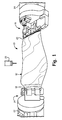
- FIG. 1 is a perspective view of fixture system 10 that can be used for securing airfoil 12 during material removal operations.
- fixture system 10 can include root-securing fixture 14 and tip-securing fixture 16.
- Airfoil 12 can include root 18 and tip 20.
- Airfoil 12 can be, e.g., a rotor blade, such as a fan blade, compressor blade, turbine blade, or other airfoil formed of aluminum, titanium, or other lightweight material having high tensile strength properties.
- Root-securing fixture 14 can be configured to secure root 18 during the material removal process, such as by fixedly clamping or otherwise securing root 18.
- Tip-securing fixture 16 can be configured to selectively engage and disengage tip 20 during the material removal process, as is further described below.
- airfoils used in turbomachinery are cast or forged to an initial form that approximates a final shape of the airfoil as defined by design specifications. Thereafter, the airfoil is subjected to a material removal process that removes excess material to shape the airfoil to meet the design specifications.
- a material removal process that removes excess material to shape the airfoil to meet the design specifications.
- airfoil 12 can be secured (e.g., by root-securing fixture 14 and tip-securing fixture 16) within a milling machine, such as a computer numerical control (CNC) system that includes drills, lathes, cutters, or other tooling to remove excess material from the airfoil.
- CNC computer numerical control
- root-securing fixture 14 and tip-securing fixture 16 can be connected to rotating headstocks 22 and 24, respectively.
- Each of rotating headstocks 22 and 24 can rotate (e.g., as controlled by a control system included in or coupled to the milling machine) about an axis of rotation that, in the example of FIG. 1 , extends radially along a span of airfoil 12.
- each of headstocks 22 and 24 can be movable to provide six degrees of freedom during material removal by, e.g., tooling 26. While the material removal process is described in the example of FIG. 1 with respect to a milling machine, it should be appreciated that techniques of this disclosure are not so limited, but may be applicable to other material removal processes, such as electrical discharge machining (EDM) operations.
- EDM electrical discharge machining
- tip-securing fixture 16 can be configured to disengage tip 20 after initial material removal from airfoil 12 to enable movement of tip 20 from a clamped-state position (i.e., a position of tip 20 prior to the initial material removal) to a new, free-state position (i.e., a position of tip 20 after initial material removal).
- the initial material removal can include eighty to ninety percent of the material to be removed from airfoil 12 during the material removal process, though other ranges are possible.
- tip-securing fixture 16 can reengage tip 20 in the free-state position for additional material removal, such as removal of a remainder of material to conform a shape of airfoil 12 to design specifications.
- fixture system 10 can decrease an amount of deformation of airfoil 12 (e.g., at tip 20) due to the release of stresses internal to airfoil 12.
- FIG. 2 is an enlarged perspective view of tip-securing fixture 16 of FIG. 1 .
- airfoil 12 can include leading edge 28 and trailing edge 30.
- Tip 20 of airfoil 12 can include radially outer edge 32.
- Each of leading edge tab 34, trailing edge tab 36, and center tab 38 extend from radially outer edge 32 and can be integrally formed from tip 20 during prior machining operations to facilitate interaction of tip-securing fixture 16 with airfoil 12.
- one or more of tabs 34, 36, and 38 can be added to tip 20, such as by welding or other operations.
- Leading edge tab 34 is disposed proximate leading edge 28 of airfoil 12.
- Trailing edge tab 36 is disposed proximate trailing edge 30 of airfoil 12.
- Center tab 38 is disposed along radially outer edge 32 between leading edge tab 34 and trailing edge tab 36, such as at or near a central radial axis of airfoil 12.
- tip-securing fixture 16 can include leading edge clamping assembly 40, trailing edge clamping assembly 42, and centering pin 44.
- Leading edge clamping assembly 40 includes leading edge positioning member 46 and leading edge clamping member 48.
- Trailing edge clamping assembly 42 includes trailing edge positioning member 50 and trailing edge clamping member 52.
- Leading edge clamping assembly 40, trailing edge clamping assembly 42, and centering pin 44 are configured to be selectively engageable and disengageable from leading edge tab 34, trailing edge tab 36, and center tab 38, respectively.
- positioning member 46 is movable to engage and disengage a forward side of leading edge tab 34.
- Leading edge clamping member 48 is movable to engage and disengage an aft side of leading edge tab 34.
- Trailing edge positioning member 50 is movable to engage and disengage an aft side of trailing edge tab 36.
- Trailing edge clamping member is movable to engage and disengage a forward side of trailing edge tab 36.
- Centering pin 44 is movable to engage and disengage a bore (not illustrated) that extends radially inward from a radially outer side of center tab 38.
- centering pin 44 engages center tab 38, leading edge clamping assembly 40 engages leading edge tab 34, and trailing edge clamping assembly 42 engages trailing edge tab 36 during initial material removal from airfoil 12.
- a threshold amount of material removal e.g., eighty to ninety percent of the material to be removed during the material removal process
- centering pin 44 disengages center tab 38, leading edge clamping assembly 40 disengages leading edge tab 34, and trailing edge clamping assembly 42 disengages trailing edge tab 36 to allow movement of tip 20 from a clamped-state position to a new, free-state position.
- leading edge clamping assembly 40 and trailing edge clamping assembly 42 reengage leading edge tab 34 and trailing edge tab 36, respectively, during additional removal of material from airfoil 12.
- centering pin 44 remains in a disengaged position (e.g., retracted from the bore of center tab 38) during the additional removal of material.
- FIG. 3 is a flow diagram illustrating example operations of fixture system 10 to selectively engage and disengage tip 20 of airfoil 12. Further details of each of the example operations of FIG. 3 are described below with respect to the following figures.
- Tip-securing fixture 16 can engage centering pin 44 with center tab 38 (step 54). Tip-securing fixture 16 can engage leading edge positioning member 46 with a forward side of leading edge tab 34, and can engage trailing edge positioning member 50 with an aft side of trailing edge tab 36 (step 56). Tip-securing fixture 16 can engage leading edge clamping member 48 with an aft side of leading edge tab 34, and can engage trailing edge clamping member 52 with a forward side of trailing edge tab 36 (step 58). Material can be removed from airfoil 12 (step 60).
- Tip-securing fixture 16 can disengage centering pin 44 from center tab 38, leading edge positioning member 46 from leading edge tab 34, leading edge clamping member 48 from leading edge tab 34, trailing edge positioning member 50 from trailing edge tab 36, and trailing edge clamping member 52 from trailing edge tab 36 to allow movement of tip 20 from a clamped-state position to a free-state position (step 62).
- Tip-securing fixture 16 can reengage leading edge positioning member 46 with the forward side of leading edge tab 34 in the free-state position, and can reengage trailing edge positioning member 50 with the aft side of trailing edge tab 36 in the free-state position (step 64). Tip-securing fixture 16 can reengage leading edge clamping member 48 with the aft side of leading edge tab 34 in the free-state position, and can reengage trailing edge clamping member 52 with the forward side of trailing edge tab 36 in the free-state position (step 66). Additional material can be removed from airfoil 12 (step 68).
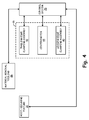
- FIG. 4 is a schematic block diagram illustrating control system 70 that can be utilized for control of fixture system 10.
- Control system 70 can be any combination of software and/or hardware configured to control operation of fixture system 10 to selectively engage and disengage tip-securing fixture 16 with tip 20 of airfoil 12.
- Control system 70 can include, in some examples, one or more processors and computer-readable memory configured to store instructions that, when executed by the one or more processors, cause fixture system 10 to operate in accordance with techniques described herein.
- processors include any one or more of a microprocessor, a controller, a digital signal processor (DSP), an application specific integrated circuit (ASIC), a field-programmable gate array (FPGA), or other equivalent discrete or integrated logic circuitry.
- Computer-readable memory can include volatile memory, such as random access memories (RAM), dynamic random access memories (DRAM), static random access memories (SRAM), and other forms of volatile memories.
- computer-readable memory can include non-volatile memory, such as magnetic hard discs, optical discs, floppy discs, flash memories, or forms of electrically programmable memories (EPROM) or electrically erasable and programmable memories (EEPROM).
- computer-readable memory can include a non-transitory medium. The term "non-transitory" can indicate that the storage medium is not embodied in a carrier wave or a propagated signal.
- Control system 70 can, in some examples, be considered a controller device configured to control operation of fixture system 10 to secure airfoil 12 during a material removal process.
- control system 70 can be integrated with a material removal machine, such as a CNC milling machine.
- control system 70 can be separate from, but communicatively coupled to, one or more of the material removal machine and fixture system 10.
- control system 70 can be coupled with material removal tooling 26, root-securing fixture 14, and leading edge clamping assembly 40, trailing edge clamping assembly 42, and centering pin 44 of tip-securing fixture 16.
- Such couplings can include any one or more of electrical couplings and communicative couplings (e.g., via a computer network).
- control system 70 can include any combination of hardware and/or software configured to control operation of fixture system 10, such as to cause tip-securing fixture 16 to engage tip 20 during initial material removal, disengage tip 20 to allow movement of tip 20 from a clamped-state position to a free-state position, and to reengage tip 20 in the free-state position for additional material removal.
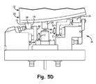
- FIGS. 5A-5D illustrate example states of tip-securing fixture 16 to engage, release, and reengage tip 20 of airfoil 12.
- FIG. 5A illustrates an example of tip-securing fixture 16 engaged with tip 20, such as during initial material removal from airfoil 12.
- FIG. 5B illustrates an example of tip-securing fixture 16 disengaged from tip 20 to allow movement of tip 20 from a clamped-state position to a free-state position.
- FIG. 5C illustrates an example of tip-securing fixture 16 with leading edge positioning member 46 reengaged with leading edge tab 34 and trailing edge positioning member 50 reengaged with trailing edge tab 36 in the free-state position of tip 20.
- FIG. 5A illustrates an example of tip-securing fixture 16 engaged with tip 20, such as during initial material removal from airfoil 12.
- FIG. 5B illustrates an example of tip-securing fixture 16 disengaged from tip 20 to allow movement of tip 20 from a clamped-state position to a free-state position.
- 5D illustrates an example of tip-securing fixture 16 with leading edge positioning member 46 and leading edge clamping member 48 engaged with leading edge tab 34, and trailing edge positioning member 50 and trailing edge clamping member 52 engaged with trailing edge tab 36 in the free-state position of tip 20.
- FIG. 5A is a perspective view of tip-securing fixture 16 engaged with tip 20 of airfoil 12.
- leading edge positioning member 46 is engaged with forward side 72 of leading edge tab 34.
- Leading edge clamping member 48 is engaged with aft side 74 of leading edge tab 34.
- leading edge clamping member 48 applies force (e.g., ninety bars, one hundred bars, or other amounts of force) against leading edge tab 34 in a direction that is generally opposite leading edge positioning member 46, which may be locked into a stationary position upon engagement with forward side 72, as is further described below.
- leading edge clamping member 48 and leading edge positioning member 46 together act to apply a clamping force to leading edge tab 34 to secure leading edge tab 34 within tip-securing fixture 16.
- centering pin 44 is engaged within a bore of center tab 38 to engage centering pin 44 with center tab 38.
- Trailing edge positioning member 50 is engaged with aft side 50 of trailing edge tab 36.
- Trailing edge clamping member 52 is engaged with forward side 78 of trailing edge tab 36.
- trailing edge clamping member 52 applies force, such as ninety bars (approximately one-thousand three-hundred and five pounds per square inch), one hundred bars (approximately one-thousand four-hundred and fifty pounds per square inch), or other amounts of force against trailing edge tab 36 in a direction that is generally opposite trailing edge positioning member 50, which may be locked into a stationary position upon engagement with aft side 76, as is further described below.
- trailing edge clamping member 52 and trailing edge positioning member 50 together act to apply a clamping force to trailing edge tab 36 to secure trailing edge tab 36 within tip-securing fixture 16.
- FIG. 5B is a perspective view of tip-securing fixture 16 disengaged from tip 20 of airfoil 12.
- leading edge positioning member 46 is disengaged from forward face 72 of leading edge tab 34.
- Leading edge clamping member 48 is disengaged from aft face 74 of leading edge tab 34.
- Centering pin 44 is disengaged from center tab 38.
- Trailing edge positioning member 50 is disengaged from aft face 76 of trailing edge tab 36.
- Trailing edge clamping member 52 is disengaged from forward face 78 of trailing edge tab 36.
- each of leading edge positioning member 46, leading edge clamping member 48, trailing edge positioning member 50, trailing edge clamping member 52, and centering pin 44 are movable to selectively engage and disengage tabs 34, 36, and 38.
- Each of leading edge positioning member 46, leading edge clamping member 48, trailing edge positioning member 50, trailing edge clamping member 52, and centering pin 44 can be pneumatically, hydraulically, or electrically actuated to induce such movement.
- tip-securing fixture 16 can include one or more of a pneumatic actuator, a hydraulic actuator, and an electrically-driven actuator (e.g., an electric motor) which can be driven by controller 70 (illustrated in FIG.
- tip-securing fixture 16 can be connected to any one or more of a pneumatic, hydraulic, and electrical actuator, e.g., via electrical connections or supply lines.
- Leading edge positioning member 46 is movable to extend and retract in the illustrated direction A. In operation, leading edge positioning member 46 retracts away from forward face 72 along direction A to disengage forward face 72.
- Leading edge clamping member 48 is movable to extend and retract in the illustrated direction B. In addition, leading edge clamping member 48 is rotatable in direction C. In operation, leading edge clamping member 48 extends away from aft face 74 along direction B to disengage aft face 74. Thereafter, leading edge clamping member 48 rotates in direction C to misalign with leading edge tab 34.
- Centering pin 44 is movable to extend and retract in the illustrated direction D. In operation, centering pin 44 retracts from the bore in center tab 38 to disengage center tab 38.
- Trailing edge clamping member 52 is movable to extend and retract in direction E. In addition, trailing edge clamping member 52 is rotatable in direction F. In operation, trailing edge clamping member 52 extends away from forward face 78 along direction E to disengage forward face 78. Thereafter, trailing edge clamping member 52 rotates in direction F to misalign with trailing edge tab 36.
- trailing edge clamping assembly 42 further includes actuator 80, which connects to trailing edge positioning member 50.
- Trailing edge positioning member 50 is connected to trailing edge clamping assembly via pivot 82.
- actuator 80 e.g., a pneumatic actuator, a hydraulic actuator, an electrically driven actuator, or other type of actuator
- actuator 80 is movable to extend and retract in direction G. Movement of actuator 80 along direction G causes rotation of trailing edge positioning member 50 in direction H via pivot 82.
- actuator 80 retracts in direction G to cause rotation of trailing edge positioning member 50 in direction H away from aft face 76 of trailing edge tab 36.
- FIG. 5C is a perspective view of tip-securing fixture 16 illustrating leading edge positioning member 46 reengaged with forward face 72 of leading edge tab 34, and trailing edge positioning member 50 reengaged with aft face 76 of trailing edge tab 36.
- leading edge clamping member 48 is disengaged from aft face 74
- trailing edge clamping member 52 is disengaged from forward face 78
- centering pin 44 is disengaged from center tab 38.
- leading edge positioning member 46 and trailing edge positioning member 50 can move to an engaged position before either of leading edge clamping member 48 and trailing edge clamping member 52 move to engagement positions.
- leading edge positioning member 46 can move along direction A into engagement with forward face 72 at a substantially same time as trailing edge positioning member 50 rotates in direction H into engagement with aft face 76.
- a force applied by leading edge positioning member 46 and trailing edge positioning member 50 can be generally opposing in a direction substantially along a chord of airfoil 12, thereby minimizing any deformation due to the engagement of positioning members 46 and 50.
- each of positioning members 46 and 50 can be maintained in a stationary position (e.g., "locked” into place) in response to application of a relatively small, threshold amount of force, such as a force of less than five Newtons (approximately one pound of force), though other threshold amounts of force are possible.
- a relatively small, threshold amount of force such as a force of less than five Newtons (approximately one pound of force)
- Such a small application of force can enable positioning members 46 and 50 to effectively locate tabs 34 and 36, respectively, while airfoil 12 is in the free-state position and without causing substantial deformation of airfoil 12.
- positioning members 46 and 50 can provide a counter force for clamping by leading edge clamping member 48 and trailing edge clamping member 52.
- clamping members 48 and 52 can each apply a relatively large clamping force, such as ninety to one hundred bars, although other ranges are possible. In this way, clamping members 48 and 52 can secure tip 20 in the free-state position without causing substantial deformation of airfoil 12 due to the applied clamping force.
- FIG. 5D is a perspective view of tip-securing fixture 16 illustrating leading edge clamping member 48 reengaged with aft face 74 of leading edge tab 34 and trailing edge clamping member 52 reengaged with forward face 78 of trailing edge tab 36.
- centering pin 44 is disengaged from center tab 38.
- centering pin 44 can be maintained in a disengaged position during additional removal of material from airfoil 12, thereby compensating for movement of tip 20 that could misalign centering pin 44 from the bore in center tab 38.
- leading edge clamping member 48 rotates in direction C to align with leading edge tab 34. Thereafter, leading edge clamping member 48 retracts along direction B to engage aft face 74 and apply a clamping force (e.g., one hundred bars of force). Trailing edge clamping member 52 rotates in direction F to align with trailing edge tab 36. Thereafter, trailing edge clamping member 52 retracts along direction E to engage forward face 78 and apply a clamping force (e.g., one hundred bars of force).
- a clamping force e.g., one hundred bars of force
- fixture system 10 implementing techniques of this disclosure can cause tip-securing fixture 16 to disengage tip 20 of airfoil 12 after initial removal of material to allow movement of tip 20 from a clamped-state position to a free-state position. Thereafter, fixture system 10 can cause tip-securing fixture 16 to reengage tip 20 for additional removal of material without causing significant deformation from the free-state position. As such, fixture system 10 can decrease a total amount of deformation of airfoil 12 caused by the release of internal stresses during the material removal process.
- a method of removing material from an airfoil includes engaging a root of the airfoil within a root-securing fixture, engaging a tip of the airfoil within a tip-securing fixture, and removing material from the airfoil. The method further includes disengaging the tip of the airfoil from the tip-securing fixture to allow movement of the tip from a clamped-state position to a free-state position, reengaging the tip of the airfoil within the tip-securing fixture in the free-state position, and removing additional material from the airfoil.
- the method of the preceding paragraph can optionally include, additionally and/or alternatively, any one or more of the following features, configurations, operations, and/or additional components:
- the plurality of tabs can include a leading edge tab proximate a leading edge of the airfoil, a trailing edge tab proximate a trailing edge of the airfoil, and a center tab disposed between the leading edge tab and the trailing edge tab.
- the center tab can have a bore extending radially inward from a radially outer side of the center tab.
- the tip-securing fixture can include a leading edge clamping assembly configured to be selectively engageable and disengageable from the leading edge tab, a trailing edge clamping assembly configured to be selectively engageable and disengageable from the trailing edge tab, and a centering pin configured to be selectively inserted into and retracted from the bore of the center tab.
- Engaging the tip of the airfoil within the tip-securing fixture can include engaging the leading edge clamping assembly with the leading edge tab, engaging the trailing edge clamping assembly with the trailing edge tab, and inserting the centering pin into the bore of the center tab.
- Disengaging the tip of the airfoil from the tip-securing fixture can include disengaging the leading edge clamping assembly from the leading edge tab, disengaging the trailing edge clamping assembly from the trailing edge tab, and retracting the centering pin from the bore of the center tab.
- Reengaging the tip of the airfoil within the tip-securing fixture can include engaging the leading edge clamping assembly with the leading edge tab and engaging the trailing edge clamping assembly with the trailing edge tab.
- Reengaging the tip of the airfoil within the tip-securing fixture can include maintaining the centering pin in a disengaged state.
- Engaging the centering pin in the bore of the centering tab can include moving the centering pin into the bore of the centering tab.
- Engaging the leading edge tab within the leading edge clamping assembly can include moving a leading edge positioning member of the leading edge clamping assembly into engagement with a forward side of the leading edge tab and moving a leading edge clamping member of the leading edge clamping assembly into engagement with an aft side of the leading edge tab.
- Engaging the trailing edge tab within the trailing edge clamping assembly can include moving a trailing edge positioning member of the trailing edge clamping assembly into engagement with an aft side of the trailing edge tab and moving a trailing edge clamping member of the trailing edge clamping assembly into engagement with a forward side of the trailing edge tab.
- Both of the leading edge positioning member and the trailing edge positioning member can be moved into engagement before either of the leading edge clamping member and the trailing edge clamping member are moved into engagement.
- Moving each of the leading edge clamping member and the trailing edge clamping member into engagement with the respective one of the leading edge tab and the trailing edge tab can include rotating each of the leading edge clamping member and the trailing edge clamping member into alignment with the respective one of the leading edge tab and the trailing edge tab prior to moving each of the leading edge clamping member and the trailing edge clamping member into engagement.
- Moving the leading edge positioning member into engagement can include moving the leading edge positioning member into engagement with the forward side of the leading edge tab to apply a first force.
- Moving the leading edge clamping member into engagement can include moving the leading edge clamping member into engagement with the aft side of the leading edge tab to apply a second force. The second force can be greater than the first force.
- Moving the trailing edge positioning member into engagement can include moving the trailing edge positioning member into engagement with the aft side of the trailing edge tab to apply a third force.
- Moving the trailing edge clamping member into engagement can include moving the trailing edge clamping member into engagement with the forward side of the trailing edge tab to apply a fourth force. The fourth force can be greater than the third force.
- Moving the leading edge positioning member into engagement with the forward side of the leading edge tab can include maintaining the leading edge positioning member in a stationary position in response to application of a first threshold amount of force.
- Moving the trailing edge positioning member into engagement with the aft side of the trailing edge tab can include maintaining the trailing edge positioning member in a stationary position in response to application of a second threshold amount of force.
- a fixture system for securing an airfoil during material removal operations includes a root-securing fixture configured to engage a root of the airfoil, a tip-securing fixture configured to be selectively engageable and disengageable from a tip of the airfoil, and a control system.
- the control system is configured to cause the tip-securing fixture to engage the tip during initial removal of material from the airfoil and to disengage the tip after the initial removal of material to allow movement of the tip from a clamped-state position to a free-state position.
- the control system is further configured to cause the tip-securing fixture to reengage the tip in the free-state position during additional removal of material from the airfoil.
- the fixture system of the preceding paragraph can optionally include, additionally and/or alternatively, any one or more of the following features, configurations, operations, and/or additional components:
- the plurality of tabs can include a leading edge tab proximate a leading edge of the airfoil, a trailing edge tab proximate a trailing edge of the airfoil, and a center tab disposed between the leading edge tab and the trailing edge tab.
- the center tab can have a bore extending radially inward from a radially outer side of the center tab.
- the tip-securing fixture can include a leading edge clamping assembly configured to be selectively engageable and disengageable from the leading edge tab, a trailing edge clamping assembly configured to be selectively engageable and disengageable from the trailing edge tab, and a centering pin configured to be selectively inserted into and retracted from the bore of the center tab.
- the control system can be configured to cause the tip-securing fixture to engage each of a plurality of tabs by causing the leading edge clamping assembly to engage the leading edge tab, the trailing edge clamping assembly to engage the trailing edge tab, and the centering pin to insert into the bore of the center tab.
- the control system can be configured to cause the tip-securing fixture to disengage each of the plurality of tabs by causing the leading edge clamping assembly to disengage from the leading edge tab, the trailing edge clamping assembly to disengage from the trailing edge tab, and the centering pin to retract from the bore of the center tab.
- the control system can be configured to cause the tip-securing fixture to reengage the tip in the free-state position during the additional removal of material by causing the leading edge clamping assembly to engage the leading edge tab and the trailing edge clamping assembly to engage the trailing edge tab.
- the control system can be configured to cause the tip-securing fixture to reengage the tip in the free-state position during the additional removal of material by maintaining the centering pin in a disengaged state.
- the leading edge clamping assembly can include a leading edge positioning member and a leading edge clamping member.
- the trailing edge clamping assembly can include a trailing edge positioning member and a trailing edge clamping member.
- the control system can be configured to cause the centering pin to insert into the bore of the centering tab by causing the centering pin to move into the bore of the centering tab.
- the control system can be configured to cause the leading edge clamping assembly to engage the leading edge tab by causing the leading edge positioning member to move into engagement with a forward side of the leading edge tab and causing the leading edge clamping member to move into engagement with an aft side of the leading edge tab.
- the control system can be configured to cause the trailing edge clamping assembly to engage the trailing edge tab by causing the trailing edge positioning member to move into engagement with an aft side of the trailing edge tab and causing the trailing edge clamping member to move into engagement with a forward side of the trailing edge tab.
- the control system can be configured to cause both the leading edge positioning member and the trailing edge positioning member to move into engagement before causing either of the leading edge clamping member and the trailing edge clamping member into engagement.
- the control system can be configured to cause each of the leading edge clamping member and the trailing edge clamping member to move into engagement with the respective one of the leading edge tab and the trailing edge tab by causing each of the leading edge clamping member and the trailing edge clamping member to rotate into alignment with the respective one of the leading edge tab and the trailing edge tab prior to causing each of the leading edge clamping member and the trailing edge clamping member to move into engagement.
- the control system can be configured to cause the leading edge positioning member to move into engagement by causing the leading edge positioning member to move into engagement with the forward side of the leading edge tab to apply a first force.
- the control system can be configured to cause the leading edge clamping member to move into engagement by causing the leading edge clamping member to move into engagement with the aft side of the leading edge tab to apply a second force, the second force greater than the first force.
- the control system can be configured to cause the trailing edge positioning member to move into engagement by causing the trailing edge positioning member to move into engagement with the aft side of the trailing edge tab to apply a third force.
- the control system can be configured to cause the trailing edge clamping member to move into engagement by causing the trailing edge clamping member to move into engagement with the forward side of the trailing edge tab to apply a fourth force, the fourth force greater than the third force.
- the control system can be configured to cause the leading edge positioning member to remain in a stationary position in response to application of a first threshold amount of force during engagement with the forward side of the leading edge tab.
- the control system can be configured to cause the trailing edge positioning member to remain in a stationary position in response to application of a second threshold amount of force during engagement with the aft side of the trailing edge tab.
Landscapes
- Engineering & Computer Science (AREA)
- Mechanical Engineering (AREA)
- General Engineering & Computer Science (AREA)
- Structures Of Non-Positive Displacement Pumps (AREA)
Abstract
Description
- This disclosure relates generally to turbomachinery, and in particular to manufacturing and machining of airfoils used in the turbomachinery.
- Turbomachinery can provide efficient, reliable power for a wide range of applications, including aviation and industrial power generation. Aviation applications often include turbojet, turbofan, turboprop, and turboshaft engines. Gas turbine engines are rotary-type combustion turbine engines built around a power core made up of a compressor, combustor, and turbine arranged in flow series with an upstream inlet and downstream exhaust. The compressor compresses air from the inlet, which is mixed with fuel in the combustor and ignited to generate hot combustion gas. The turbine extracts energy from the expanding combustion gas, and drives the compressor via a common shaft. Energy is delivered in the form of rotational energy in the shaft, reactive thrust from the exhaust, or both.
- Turbofan engines are commonly divided into high and low bypass configurations. High bypass turbofans generate thrust primarily from the fan, which drives airflow through a bypass duct oriented around the engine core. This design is common on commercial aircraft and military transports, where noise and fuel efficiency are primary concerns. Low bypass turbofans generate proportionally more thrust from the exhaust flow, providing greater specific thrust for use on high-performance aircraft, including supersonic jet fighters. Unducted (open rotor) turbofans and ducted propeller engines are also known, and are often utilized in a variety of counter-rotating and aft-mounted configurations.
- Turbofan and turbojet engines are often subdivided into a number of stages, which are formed of alternating rows of rotor blade and stator vane airfoils. The airfoils are shaped to turn, accelerate, and compress the working fluid flow, or to generate lift for conversion to rotational energy in, e.g., a turbine. Accordingly, efficient engine performance depends upon precise control of the working fluid flow, including flow across fan, combustor, and turbine airfoils. Such precise control requires highly accurate manufacturing techniques to form the airfoil surfaces within specified design tolerances. To this end, material is typically removed from initially-forged or cast airfoils to meet design tolerances using sophisticated tooling systems, such as computer numerical control (CNC) machining systems. Often, the airfoil is secured within the tooling system using fixtures that prevent movement of the blade during material removal. However, in some cases, the airfoil can warp or otherwise deform upon release from the fixtures, possibly resulting in a finished airfoil that does not meet design specifications.
- In one example, a method of removing material from an airfoil comprises engaging a root of the airfoil within a root-securing fixture, engaging a tip of the airfoil within a tip-securing fixture, and removing material from the airfoil. The method further includes disengaging the tip of the airfoil from the tip-securing fixture to allow movement of the tip from a clamped-state position to a free-state position, reengaging the tip of the airfoil within the tip-securing fixture in the free-state position, and removing additional material from the airfoil.
- In another example, a fixture system for securing an airfoil during material removal operations includes a root-securing fixture configured to engage a root of the airfoil, a tip-securing fixture configured to be selectively engageable and disengageable from a tip of the airfoil, and a control system. The control system is configured to cause the tip-securing fixture to engage the tip during initial removal of material from the airfoil and to disengage the tip after the initial removal of material to allow movement of the tip from a clamped-state position to a free-state position. The control system is further configured to cause the tip-securing fixture to reengage the tip in the free-state position during additional removal of material from the airfoil.
-
-
FIG. 1 is a perspective view of a fixture system that can be used for securing an airfoil during material removal operations. -
FIG. 2 is an enlarged perspective view of the tip-securing fixture ofFIG. 1 . -
FIG. 3 is a flow diagram illustrating example operations of the fixture system ofFIG. 1 to selectively engage and disengage the tip of the airfoil. -
FIG. 4 is a schematic block diagram illustrating a control system that can be utilized for control of the fixture system ofFIG. 1 . -
FIG. 5A is a perspective view of the tip-securing fixture ofFIG. 1 engaged with a tip of an airfoil. -
FIG. 5B is a perspective view of the tip-securing fixture ofFIG. 5A disengaged from the tip of the airfoil. -
FIG. 5C is a perspective view of the tip-securing fixture ofFIG. 5A illustrating positioning members reengaged with the tip of the airfoil. -
FIG. 5D is a perspective view of the tip-securing fixture ofFIG. 5A illustrating clamping members reengaged with the tip of the airfoil. - According to techniques of this disclosure, a fixture system can disengage a tip of an airfoil after initial material removal (e.g., during machining or other finishing operations), thereby helping to compensate for the release of internal stresses (e.g., forging stresses) resulting from the removal of the material. By disengaging the tip of the airfoil after the initial material removal (e.g., eighty to ninety percent of the material to be removed during the finishing operations), the fixture system can allow movement of the tip of the airfoil from a clamped-state position to a new, free-state position. Thereafter, the fixture system can reengage the tip in the free-state position for additional material removal (e.g., a remainder of the material to be removed during the finishing operations). That is, rather than reengage the airfoil by clamping the airfoil against an immobile hard-stop of the fixture that was used for initial material removal, a fixture system implementing techniques described herein can reengage the blade in the new, free-state position without causing significant deformation from the free-state position. In this way, a fixture system implementing techniques of this disclosure can help to minimize warping or other deformation of the airfoil due to internal stress relief resulting from the material removal process. Moreover, the fixture system can be automated to disengage and reengage the airfoil, thereby decreasing the amount of operator intervention (and the associated costs) required during the material removal process.
-
FIG. 1 is a perspective view offixture system 10 that can be used for securingairfoil 12 during material removal operations. As illustrated inFIG. 1 ,fixture system 10 can include root-securingfixture 14 and tip-securingfixture 16. Airfoil 12 can includeroot 18 andtip 20.Airfoil 12 can be, e.g., a rotor blade, such as a fan blade, compressor blade, turbine blade, or other airfoil formed of aluminum, titanium, or other lightweight material having high tensile strength properties. Root-securingfixture 14 can be configured to secureroot 18 during the material removal process, such as by fixedly clamping or otherwise securingroot 18. Tip-securingfixture 16 can be configured to selectively engage and disengagetip 20 during the material removal process, as is further described below. - Typically, airfoils used in turbomachinery are cast or forged to an initial form that approximates a final shape of the airfoil as defined by design specifications. Thereafter, the airfoil is subjected to a material removal process that removes excess material to shape the airfoil to meet the design specifications. For instance, as illustrated in
FIG. 1 ,airfoil 12 can be secured (e.g., by root-securingfixture 14 and tip-securing fixture 16) within a milling machine, such as a computer numerical control (CNC) system that includes drills, lathes, cutters, or other tooling to remove excess material from the airfoil. As in the example ofFIG. 1 , root-securingfixture 14 and tip-securingfixture 16 can be connected to rotatingheadstocks headstocks FIG. 1 , extends radially along a span ofairfoil 12. In addition, each ofheadstocks tooling 26. While the material removal process is described in the example ofFIG. 1 with respect to a milling machine, it should be appreciated that techniques of this disclosure are not so limited, but may be applicable to other material removal processes, such as electrical discharge machining (EDM) operations. - The initial casting or forging process can introduce internal stresses within
airfoil 12. Removal of material from the cast/forged state can relieve such internal stresses, thereby causing warping or other deformation ofairfoil 12 upon release fromfixture system 10. Such deformation can be particularly pronounced at thinner parts ofairfoil 12, such as at ornear tip 20. Accordingly, as is further described below, tip-securingfixture 16 can be configured to disengagetip 20 after initial material removal fromairfoil 12 to enable movement oftip 20 from a clamped-state position (i.e., a position oftip 20 prior to the initial material removal) to a new, free-state position (i.e., a position oftip 20 after initial material removal). As one example, the initial material removal can include eighty to ninety percent of the material to be removed fromairfoil 12 during the material removal process, though other ranges are possible. Thereafter, tip-securingfixture 16 can reengagetip 20 in the free-state position for additional material removal, such as removal of a remainder of material to conform a shape ofairfoil 12 to design specifications. As such,fixture system 10 can decrease an amount of deformation of airfoil 12 (e.g., at tip 20) due to the release of stresses internal toairfoil 12. -
FIG. 2 is an enlarged perspective view of tip-securingfixture 16 ofFIG. 1 . As illustrated inFIG. 2 ,airfoil 12 can include leadingedge 28 and trailingedge 30.Tip 20 ofairfoil 12 can include radiallyouter edge 32. Each of leadingedge tab 34, trailingedge tab 36, andcenter tab 38 extend from radiallyouter edge 32 and can be integrally formed fromtip 20 during prior machining operations to facilitate interaction of tip-securingfixture 16 withairfoil 12. In other examples, one or more oftabs tip 20, such as by welding or other operations. Leadingedge tab 34 is disposed proximate leadingedge 28 ofairfoil 12. Trailingedge tab 36 is disposedproximate trailing edge 30 ofairfoil 12.Center tab 38 is disposed along radiallyouter edge 32 between leadingedge tab 34 and trailingedge tab 36, such as at or near a central radial axis ofairfoil 12. - As further illustrated in
FIG. 2 , tip-securingfixture 16 can include leadingedge clamping assembly 40, trailingedge clamping assembly 42, and centeringpin 44. Leadingedge clamping assembly 40 includes leadingedge positioning member 46 and leadingedge clamping member 48. Trailingedge clamping assembly 42 includes trailingedge positioning member 50 and trailingedge clamping member 52. - Leading
edge clamping assembly 40, trailingedge clamping assembly 42, and centeringpin 44 are configured to be selectively engageable and disengageable from leadingedge tab 34, trailingedge tab 36, andcenter tab 38, respectively. For instance, as is further described below, positioningmember 46 is movable to engage and disengage a forward side of leadingedge tab 34. Leadingedge clamping member 48 is movable to engage and disengage an aft side of leadingedge tab 34. Trailingedge positioning member 50 is movable to engage and disengage an aft side of trailingedge tab 36. Trailing edge clamping member is movable to engage and disengage a forward side of trailingedge tab 36. Centeringpin 44 is movable to engage and disengage a bore (not illustrated) that extends radially inward from a radially outer side ofcenter tab 38. - In operation, and as further described below, centering
pin 44 engagescenter tab 38, leadingedge clamping assembly 40 engages leadingedge tab 34, and trailingedge clamping assembly 42 engages trailingedge tab 36 during initial material removal fromairfoil 12. In response to a threshold amount of material removal (e.g., eighty to ninety percent of the material to be removed during the material removal process), centeringpin 44disengages center tab 38, leadingedge clamping assembly 40 disengages leadingedge tab 34, and trailingedge clamping assembly 42 disengages trailingedge tab 36 to allow movement oftip 20 from a clamped-state position to a new, free-state position. Thereafter, leadingedge clamping assembly 40 and trailingedge clamping assembly 42 reengage leadingedge tab 34 and trailingedge tab 36, respectively, during additional removal of material fromairfoil 12. In some examples, centeringpin 44 remains in a disengaged position (e.g., retracted from the bore of center tab 38) during the additional removal of material. -
FIG. 3 is a flow diagram illustrating example operations offixture system 10 to selectively engage and disengagetip 20 ofairfoil 12. Further details of each of the example operations ofFIG. 3 are described below with respect to the following figures. - Tip-securing
fixture 16 can engage centeringpin 44 with center tab 38 (step 54). Tip-securingfixture 16 can engage leadingedge positioning member 46 with a forward side of leadingedge tab 34, and can engage trailingedge positioning member 50 with an aft side of trailing edge tab 36 (step 56). Tip-securingfixture 16 can engage leadingedge clamping member 48 with an aft side of leadingedge tab 34, and can engage trailingedge clamping member 52 with a forward side of trailing edge tab 36 (step 58). Material can be removed from airfoil 12 (step 60). Tip-securingfixture 16 can disengage centeringpin 44 fromcenter tab 38, leadingedge positioning member 46 from leadingedge tab 34, leadingedge clamping member 48 from leadingedge tab 34, trailingedge positioning member 50 from trailingedge tab 36, and trailingedge clamping member 52 from trailingedge tab 36 to allow movement oftip 20 from a clamped-state position to a free-state position (step 62). - Tip-securing
fixture 16 can reengage leadingedge positioning member 46 with the forward side of leadingedge tab 34 in the free-state position, and can reengage trailingedge positioning member 50 with the aft side of trailingedge tab 36 in the free-state position (step 64). Tip-securingfixture 16 can reengage leadingedge clamping member 48 with the aft side of leadingedge tab 34 in the free-state position, and can reengage trailingedge clamping member 52 with the forward side of trailingedge tab 36 in the free-state position (step 66). Additional material can be removed from airfoil 12 (step 68). -
FIG. 4 is a schematic block diagram illustratingcontrol system 70 that can be utilized for control offixture system 10.Control system 70 can be any combination of software and/or hardware configured to control operation offixture system 10 to selectively engage and disengage tip-securingfixture 16 withtip 20 ofairfoil 12.Control system 70 can include, in some examples, one or more processors and computer-readable memory configured to store instructions that, when executed by the one or more processors,cause fixture system 10 to operate in accordance with techniques described herein. - Examples of one or more processors include any one or more of a microprocessor, a controller, a digital signal processor (DSP), an application specific integrated circuit (ASIC), a field-programmable gate array (FPGA), or other equivalent discrete or integrated logic circuitry. Computer-readable memory can include volatile memory, such as random access memories (RAM), dynamic random access memories (DRAM), static random access memories (SRAM), and other forms of volatile memories. In some examples, computer-readable memory can include non-volatile memory, such as magnetic hard discs, optical discs, floppy discs, flash memories, or forms of electrically programmable memories (EPROM) or electrically erasable and programmable memories (EEPROM). In certain examples, computer-readable memory can include a non-transitory medium. The term "non-transitory" can indicate that the storage medium is not embodied in a carrier wave or a propagated signal.
-
Control system 70 can, in some examples, be considered a controller device configured to control operation offixture system 10 to secureairfoil 12 during a material removal process. In certain examples,control system 70 can be integrated with a material removal machine, such as a CNC milling machine. In other examples,control system 70 can be separate from, but communicatively coupled to, one or more of the material removal machine andfixture system 10. - As illustrated in
FIG. 4 ,control system 70 can be coupled withmaterial removal tooling 26, root-securingfixture 14, and leadingedge clamping assembly 40, trailingedge clamping assembly 42, and centeringpin 44 of tip-securingfixture 16. Such couplings can include any one or more of electrical couplings and communicative couplings (e.g., via a computer network). In general,control system 70 can include any combination of hardware and/or software configured to control operation offixture system 10, such as to cause tip-securingfixture 16 to engagetip 20 during initial material removal, disengagetip 20 to allow movement oftip 20 from a clamped-state position to a free-state position, and to reengagetip 20 in the free-state position for additional material removal. -
FIGS. 5A-5D illustrate example states of tip-securingfixture 16 to engage, release, and reengagetip 20 ofairfoil 12. Specifically,FIG. 5A illustrates an example of tip-securingfixture 16 engaged withtip 20, such as during initial material removal fromairfoil 12.FIG. 5B illustrates an example of tip-securingfixture 16 disengaged fromtip 20 to allow movement oftip 20 from a clamped-state position to a free-state position.FIG. 5C illustrates an example of tip-securingfixture 16 with leadingedge positioning member 46 reengaged with leadingedge tab 34 and trailingedge positioning member 50 reengaged with trailingedge tab 36 in the free-state position oftip 20.FIG. 5D illustrates an example of tip-securingfixture 16 with leadingedge positioning member 46 and leadingedge clamping member 48 engaged withleading edge tab 34, and trailingedge positioning member 50 and trailingedge clamping member 52 engaged with trailingedge tab 36 in the free-state position oftip 20. -
FIG. 5A is a perspective view of tip-securingfixture 16 engaged withtip 20 ofairfoil 12. As illustrated inFIG. 5A , leadingedge positioning member 46 is engaged withforward side 72 of leadingedge tab 34. Leadingedge clamping member 48 is engaged withaft side 74 of leadingedge tab 34. In operation, leadingedge clamping member 48 applies force (e.g., ninety bars, one hundred bars, or other amounts of force) against leadingedge tab 34 in a direction that is generally opposite leadingedge positioning member 46, which may be locked into a stationary position upon engagement withforward side 72, as is further described below. In this way, leadingedge clamping member 48 and leadingedge positioning member 46 together act to apply a clamping force to leadingedge tab 34 to secureleading edge tab 34 within tip-securingfixture 16. - As further illustrated in
FIG. 5A , centeringpin 44 is engaged within a bore ofcenter tab 38 to engage centeringpin 44 withcenter tab 38. Trailingedge positioning member 50 is engaged withaft side 50 of trailingedge tab 36. Trailingedge clamping member 52 is engaged withforward side 78 of trailingedge tab 36. In operation, trailingedge clamping member 52 applies force, such as ninety bars (approximately one-thousand three-hundred and five pounds per square inch), one hundred bars (approximately one-thousand four-hundred and fifty pounds per square inch), or other amounts of force against trailingedge tab 36 in a direction that is generally opposite trailingedge positioning member 50, which may be locked into a stationary position upon engagement withaft side 76, as is further described below. As such, trailingedge clamping member 52 and trailingedge positioning member 50 together act to apply a clamping force to trailingedge tab 36 to secure trailingedge tab 36 within tip-securingfixture 16. -
FIG. 5B is a perspective view of tip-securingfixture 16 disengaged fromtip 20 ofairfoil 12. As illustrated inFIG. 5B , leadingedge positioning member 46 is disengaged fromforward face 72 of leadingedge tab 34. Leadingedge clamping member 48 is disengaged fromaft face 74 of leadingedge tab 34. Centeringpin 44 is disengaged fromcenter tab 38. Trailingedge positioning member 50 is disengaged fromaft face 76 of trailingedge tab 36. Trailingedge clamping member 52 is disengaged fromforward face 78 of trailingedge tab 36. - As illustrated, each of leading
edge positioning member 46, leadingedge clamping member 48, trailingedge positioning member 50, trailingedge clamping member 52, and centeringpin 44 are movable to selectively engage and disengagetabs edge positioning member 46, leadingedge clamping member 48, trailingedge positioning member 50, trailingedge clamping member 52, and centeringpin 44 can be pneumatically, hydraulically, or electrically actuated to induce such movement. As one example, tip-securingfixture 16 can include one or more of a pneumatic actuator, a hydraulic actuator, and an electrically-driven actuator (e.g., an electric motor) which can be driven by controller 70 (illustrated inFIG. 4 ) to cause movement of leadingedge positioning member 46, leadingedge clamping member 48, trailingedge positioning member 50, trailingedge clamping member 52, and centeringpin 44. As another example, tip-securingfixture 16 can be connected to any one or more of a pneumatic, hydraulic, and electrical actuator, e.g., via electrical connections or supply lines. - Leading
edge positioning member 46 is movable to extend and retract in the illustrated direction A. In operation, leadingedge positioning member 46 retracts away fromforward face 72 along direction A to disengageforward face 72. Leadingedge clamping member 48 is movable to extend and retract in the illustrated direction B. In addition, leadingedge clamping member 48 is rotatable in direction C. In operation, leadingedge clamping member 48 extends away fromaft face 74 along direction B to disengageaft face 74. Thereafter, leadingedge clamping member 48 rotates in direction C to misalign withleading edge tab 34. - Centering
pin 44 is movable to extend and retract in the illustrated direction D. In operation, centeringpin 44 retracts from the bore incenter tab 38 to disengagecenter tab 38. Trailingedge clamping member 52 is movable to extend and retract in direction E. In addition, trailingedge clamping member 52 is rotatable in direction F. In operation, trailingedge clamping member 52 extends away fromforward face 78 along direction E to disengageforward face 78. Thereafter, trailingedge clamping member 52 rotates in direction F to misalign with trailingedge tab 36. - As illustrated in
FIG. 5B , trailingedge clamping assembly 42 further includesactuator 80, which connects to trailingedge positioning member 50. Trailingedge positioning member 50 is connected to trailing edge clamping assembly viapivot 82. In operation, actuator 80 (e.g., a pneumatic actuator, a hydraulic actuator, an electrically driven actuator, or other type of actuator) is movable to extend and retract in direction G. Movement ofactuator 80 along direction G causes rotation of trailingedge positioning member 50 in direction H viapivot 82. In operation,actuator 80 retracts in direction G to cause rotation of trailingedge positioning member 50 in direction H away fromaft face 76 of trailingedge tab 36. -
FIG. 5C is a perspective view of tip-securingfixture 16 illustrating leadingedge positioning member 46 reengaged withforward face 72 of leadingedge tab 34, and trailingedge positioning member 50 reengaged withaft face 76 of trailingedge tab 36. As illustrated inFIG. 5C , leadingedge clamping member 48 is disengaged fromaft face 74, trailingedge clamping member 52 is disengaged fromforward face 78, and centeringpin 44 is disengaged fromcenter tab 38. In some examples, such as the example ofFIG. 5C , leadingedge positioning member 46 and trailingedge positioning member 50 can move to an engaged position before either of leadingedge clamping member 48 and trailingedge clamping member 52 move to engagement positions. - For instance, as in the example of
FIG. 5C , leadingedge positioning member 46 can move along direction A into engagement withforward face 72 at a substantially same time as trailingedge positioning member 50 rotates in direction H into engagement withaft face 76. As such, a force applied by leadingedge positioning member 46 and trailingedge positioning member 50 can be generally opposing in a direction substantially along a chord ofairfoil 12, thereby minimizing any deformation due to the engagement ofpositioning members members positioning members tabs airfoil 12 is in the free-state position and without causing substantial deformation ofairfoil 12. By maintainingpositioning members members edge clamping member 48 and trailingedge clamping member 52. For instance, clampingmembers members tip 20 in the free-state position without causing substantial deformation ofairfoil 12 due to the applied clamping force. -
FIG. 5D is a perspective view of tip-securingfixture 16 illustrating leadingedge clamping member 48 reengaged withaft face 74 of leadingedge tab 34 and trailingedge clamping member 52 reengaged withforward face 78 of trailingedge tab 36. As illustrated inFIG. 5D , centeringpin 44 is disengaged fromcenter tab 38. In some examples, such as the example ofFIG. 5D , centeringpin 44 can be maintained in a disengaged position during additional removal of material fromairfoil 12, thereby compensating for movement oftip 20 that could misalign centeringpin 44 from the bore incenter tab 38. - In operation, leading
edge clamping member 48 rotates in direction C to align withleading edge tab 34. Thereafter, leadingedge clamping member 48 retracts along direction B to engage aftface 74 and apply a clamping force (e.g., one hundred bars of force). Trailingedge clamping member 52 rotates in direction F to align with trailingedge tab 36. Thereafter, trailingedge clamping member 52 retracts along direction E to engage forward face 78 and apply a clamping force (e.g., one hundred bars of force). - Accordingly,
fixture system 10 implementing techniques of this disclosure can cause tip-securingfixture 16 to disengagetip 20 ofairfoil 12 after initial removal of material to allow movement oftip 20 from a clamped-state position to a free-state position. Thereafter,fixture system 10 can cause tip-securingfixture 16 to reengagetip 20 for additional removal of material without causing significant deformation from the free-state position. As such,fixture system 10 can decrease a total amount of deformation ofairfoil 12 caused by the release of internal stresses during the material removal process. - The following are non-exclusive descriptions of possible embodiments of the present invention.
- A method of removing material from an airfoil includes engaging a root of the airfoil within a root-securing fixture, engaging a tip of the airfoil within a tip-securing fixture, and removing material from the airfoil. The method further includes disengaging the tip of the airfoil from the tip-securing fixture to allow movement of the tip from a clamped-state position to a free-state position, reengaging the tip of the airfoil within the tip-securing fixture in the free-state position, and removing additional material from the airfoil.
- The method of the preceding paragraph can optionally include, additionally and/or alternatively, any one or more of the following features, configurations, operations, and/or additional components:
- Engaging the tip of the airfoil within the tip-securing fixture can include engaging each of a plurality of tabs extending from a radially outer edge of the tip of the airfoil within the tip-securing fixture. Disengaging the tip of the airfoil from the tip-securing fixture can include disengaging each of the plurality of tabs from the tip-securing fixture.
- The plurality of tabs can include a leading edge tab proximate a leading edge of the airfoil, a trailing edge tab proximate a trailing edge of the airfoil, and a center tab disposed between the leading edge tab and the trailing edge tab. The center tab can have a bore extending radially inward from a radially outer side of the center tab. The tip-securing fixture can include a leading edge clamping assembly configured to be selectively engageable and disengageable from the leading edge tab, a trailing edge clamping assembly configured to be selectively engageable and disengageable from the trailing edge tab, and a centering pin configured to be selectively inserted into and retracted from the bore of the center tab. Engaging the tip of the airfoil within the tip-securing fixture can include engaging the leading edge clamping assembly with the leading edge tab, engaging the trailing edge clamping assembly with the trailing edge tab, and inserting the centering pin into the bore of the center tab. Disengaging the tip of the airfoil from the tip-securing fixture can include disengaging the leading edge clamping assembly from the leading edge tab, disengaging the trailing edge clamping assembly from the trailing edge tab, and retracting the centering pin from the bore of the center tab.
- Reengaging the tip of the airfoil within the tip-securing fixture can include engaging the leading edge clamping assembly with the leading edge tab and engaging the trailing edge clamping assembly with the trailing edge tab.
- Reengaging the tip of the airfoil within the tip-securing fixture can include maintaining the centering pin in a disengaged state.
- Engaging the centering pin in the bore of the centering tab can include moving the centering pin into the bore of the centering tab. Engaging the leading edge tab within the leading edge clamping assembly can include moving a leading edge positioning member of the leading edge clamping assembly into engagement with a forward side of the leading edge tab and moving a leading edge clamping member of the leading edge clamping assembly into engagement with an aft side of the leading edge tab. Engaging the trailing edge tab within the trailing edge clamping assembly can include moving a trailing edge positioning member of the trailing edge clamping assembly into engagement with an aft side of the trailing edge tab and moving a trailing edge clamping member of the trailing edge clamping assembly into engagement with a forward side of the trailing edge tab.
- Both of the leading edge positioning member and the trailing edge positioning member can be moved into engagement before either of the leading edge clamping member and the trailing edge clamping member are moved into engagement.
- Moving each of the leading edge clamping member and the trailing edge clamping member into engagement with the respective one of the leading edge tab and the trailing edge tab can include rotating each of the leading edge clamping member and the trailing edge clamping member into alignment with the respective one of the leading edge tab and the trailing edge tab prior to moving each of the leading edge clamping member and the trailing edge clamping member into engagement.
- Moving the leading edge positioning member into engagement can include moving the leading edge positioning member into engagement with the forward side of the leading edge tab to apply a first force. Moving the leading edge clamping member into engagement can include moving the leading edge clamping member into engagement with the aft side of the leading edge tab to apply a second force. The second force can be greater than the first force. Moving the trailing edge positioning member into engagement can include moving the trailing edge positioning member into engagement with the aft side of the trailing edge tab to apply a third force. Moving the trailing edge clamping member into engagement can include moving the trailing edge clamping member into engagement with the forward side of the trailing edge tab to apply a fourth force. The fourth force can be greater than the third force.
- Moving the leading edge positioning member into engagement with the forward side of the leading edge tab can include maintaining the leading edge positioning member in a stationary position in response to application of a first threshold amount of force. Moving the trailing edge positioning member into engagement with the aft side of the trailing edge tab can include maintaining the trailing edge positioning member in a stationary position in response to application of a second threshold amount of force.
- A fixture system for securing an airfoil during material removal operations includes a root-securing fixture configured to engage a root of the airfoil, a tip-securing fixture configured to be selectively engageable and disengageable from a tip of the airfoil, and a control system. The control system is configured to cause the tip-securing fixture to engage the tip during initial removal of material from the airfoil and to disengage the tip after the initial removal of material to allow movement of the tip from a clamped-state position to a free-state position. The control system is further configured to cause the tip-securing fixture to reengage the tip in the free-state position during additional removal of material from the airfoil.
- The fixture system of the preceding paragraph can optionally include, additionally and/or alternatively, any one or more of the following features, configurations, operations, and/or additional components:
- The control system can be configured to cause the tip-securing fixture to engage the tip during the initial removal of material by causing the tip-securing fixture to engage each of a plurality of tabs extending from a radially outer edge of the tip of the airfoil within the tip-securing fixture. The control system can be configured to cause the tip-securing fixture to disengage the tip after the initial removal of material by causing the tip-securing fixture to disengage each of the plurality of tabs from the tip-securing fixture.
- The plurality of tabs can include a leading edge tab proximate a leading edge of the airfoil, a trailing edge tab proximate a trailing edge of the airfoil, and a center tab disposed between the leading edge tab and the trailing edge tab. The center tab can have a bore extending radially inward from a radially outer side of the center tab. The tip-securing fixture can include a leading edge clamping assembly configured to be selectively engageable and disengageable from the leading edge tab, a trailing edge clamping assembly configured to be selectively engageable and disengageable from the trailing edge tab, and a centering pin configured to be selectively inserted into and retracted from the bore of the center tab. The control system can be configured to cause the tip-securing fixture to engage each of a plurality of tabs by causing the leading edge clamping assembly to engage the leading edge tab, the trailing edge clamping assembly to engage the trailing edge tab, and the centering pin to insert into the bore of the center tab. The control system can be configured to cause the tip-securing fixture to disengage each of the plurality of tabs by causing the leading edge clamping assembly to disengage from the leading edge tab, the trailing edge clamping assembly to disengage from the trailing edge tab, and the centering pin to retract from the bore of the center tab.
- The control system can be configured to cause the tip-securing fixture to reengage the tip in the free-state position during the additional removal of material by causing the leading edge clamping assembly to engage the leading edge tab and the trailing edge clamping assembly to engage the trailing edge tab.
- The control system can be configured to cause the tip-securing fixture to reengage the tip in the free-state position during the additional removal of material by maintaining the centering pin in a disengaged state.
- The leading edge clamping assembly can include a leading edge positioning member and a leading edge clamping member. The trailing edge clamping assembly can include a trailing edge positioning member and a trailing edge clamping member. The control system can be configured to cause the centering pin to insert into the bore of the centering tab by causing the centering pin to move into the bore of the centering tab. The control system can be configured to cause the leading edge clamping assembly to engage the leading edge tab by causing the leading edge positioning member to move into engagement with a forward side of the leading edge tab and causing the leading edge clamping member to move into engagement with an aft side of the leading edge tab. The control system can be configured to cause the trailing edge clamping assembly to engage the trailing edge tab by causing the trailing edge positioning member to move into engagement with an aft side of the trailing edge tab and causing the trailing edge clamping member to move into engagement with a forward side of the trailing edge tab.
- The control system can be configured to cause both the leading edge positioning member and the trailing edge positioning member to move into engagement before causing either of the leading edge clamping member and the trailing edge clamping member into engagement.
- The control system can be configured to cause each of the leading edge clamping member and the trailing edge clamping member to move into engagement with the respective one of the leading edge tab and the trailing edge tab by causing each of the leading edge clamping member and the trailing edge clamping member to rotate into alignment with the respective one of the leading edge tab and the trailing edge tab prior to causing each of the leading edge clamping member and the trailing edge clamping member to move into engagement.
- The control system can be configured to cause the leading edge positioning member to move into engagement by causing the leading edge positioning member to move into engagement with the forward side of the leading edge tab to apply a first force. The control system can be configured to cause the leading edge clamping member to move into engagement by causing the leading edge clamping member to move into engagement with the aft side of the leading edge tab to apply a second force, the second force greater than the first force. The control system can be configured to cause the trailing edge positioning member to move into engagement by causing the trailing edge positioning member to move into engagement with the aft side of the trailing edge tab to apply a third force. The control system can be configured to cause the trailing edge clamping member to move into engagement by causing the trailing edge clamping member to move into engagement with the forward side of the trailing edge tab to apply a fourth force, the fourth force greater than the third force.
- The control system can be configured to cause the leading edge positioning member to remain in a stationary position in response to application of a first threshold amount of force during engagement with the forward side of the leading edge tab. The control system can be configured to cause the trailing edge positioning member to remain in a stationary position in response to application of a second threshold amount of force during engagement with the aft side of the trailing edge tab.
- While the invention has been described with reference to an exemplary embodiment(s), it will be understood by those skilled in the art that various changes may be made and equivalents may be substituted for elements thereof without departing from the scope of the invention. In addition, many modifications may be made to adapt a particular situation or material to the teachings of the invention without departing from the essential scope thereof. Therefore, it is intended that the invention not be limited to the particular embodiment(s) disclosed, but that the invention will include all embodiments falling within the scope of the appended claims.
Claims (15)
- A method of removing material from an airfoil (12), the method comprising:engaging a root (18) of the airfoil (12) within a root-securing fixture (14);engaging a tip (20) of the airfoil (12) within a tip-securing fixture (16);removing material from the airfoil (12);disengaging the tip (20) of the airfoil (12) from the tip-securing fixture (16) to allow movement of the tip (20) from a clamped state position to a free-state position;reengaging the tip (20) of the airfoil (12) within the tip-securing fixture (16) in the free-state position; andremoving additional material from the airfoil (12).
- The method of claim 1,
wherein engaging the tip (20) of the airfoil (12) within the tip-securing fixture (16) comprises engaging each of a plurality of tabs (34, 36, 38) extending from a radially outer edge (32) of the tip (20) of the airfoil (12) within the tip-securing fixture (16); and
wherein disengaging the tip (20) of the airfoil (12) from the tip-securing fixture (16) comprises disengaging each of the plurality of tabs (34, 36, 38) from the tip-securing fixture (16). - The method of claim 2,
wherein the plurality of tabs comprises a leading edge tab (34) proximate a leading edge (28) of the airfoil (12), a trailing edge tab (36) proximate a trailing edge (30) of the airfoil (12), and a center tab (38) disposed between the leading edge tab (34) and the trailing edge tab (36), the center tab (36) having a bore extending radially inward from a radially outer side of the center tab (38);
wherein the tip-securing fixture (16) comprises a leading edge clamping assembly (40) configured to be selectively engageable and disengageable from the leading edge tab (34), a trailing edge clamping assembly (42) configured to be selectively engageable and disengageable from the trailing edge tab (36), and a centering pin (44) configured to be selectively inserted into and retracted from the bore of the center tab (38);
wherein engaging the tip (20) of the airfoil (12) within the tip-securing fixture (16) comprises engaging the leading edge clamping assembly (40) with the leading edge tab (34), engaging the trailing edge clamping assembly (42) with the trailing edge tab (36), and inserting the centering pin (44) into the bore of the center tab (38); and
wherein disengaging the tip (20) of the airfoil (12) from the tip-securing fixture (16) comprises disengaging the leading edge clamping assembly (40) from the leading edge tab (34), disengaging the trailing edge clamping assembly (42) from the trailing edge tab (36), and retracting the centering pin (44) from the bore of the center tab (38). - The method of claim 3,
wherein reengaging the tip (20) of the airfoil (12) within the tip-securing fixture (46) comprises engaging the leading edge clamping assembly (40) with the leading edge tab (34) and engaging the trailing edge clamping assembly (42) with the trailing edge tab (36). - The method of claim 4, wherein reengaging the tip (20) of the airfoil (12) within the tip-securing fixture (16) comprises maintaining the centering pin (44) in a disengaged state.
- The method of claim 3, 4 or 5,
wherein engaging the centering pin (44) in the bore of the centering tab (38) comprises moving the centering pin (44) into the bore of the centering tab (38);
wherein engaging the leading edge tab (34) within the leading edge clamping assembly (40) comprises moving a leading edge positioning member (46) of the leading edge clamping assembly (40) into engagement with a forward side of the leading edge tab (34) and moving a leading edge clamping member (48) of the leading edge clamping assembly (40) into engagement with an aft side of the leading edge tab (34); and
wherein engaging the trailing edge tab (36) within the trailing edge clamping assembly (42) comprises moving a trailing edge positioning member (50) of the trailing edge clamping assembly (42) into engagement with an aft side of the trailing edge tab (36) and moving a trailing edge clamping member (52) of the trailing edge clamping assembly (42) into engagement with a forward side of the trailing edge tab (36). - The method of claim 6, wherein both of the leading edge positioning member (46) and the trailing edge positioning member (50) are moved into engagement before either of the leading edge clamping member (48) and the trailing edge clamping member (52) are moved into engagement.
- The method of claim 6 or 7, wherein moving each of the leading edge clamping member (50) and the trailing edge clamping member (52) into engagement with the respective one of the leading edge tab (34) and the trailing edge tab (36) comprises rotating each of the leading edge clamping member (50) and the trailing edge clamping member (52) into alignment with the respective one of the leading edge tab (34) and the trailing edge tab (36) prior to moving each of the leading edge clamping member (50) and the trailing edge clamping member (52) into engagement.
- The method of any of claims 6 to 8,
wherein moving the leading edge positioning member (46) into engagement comprises moving the leading edge positioning member (46) into engagement with the forward side of the leading edge tab (34) to apply a first force;
wherein moving the leading edge clamping member (48) into engagement comprises moving the leading edge clamping member (48) into engagement with the aft side of the leading edge tab (34) to apply a second force, the second force greater than the first force;
wherein moving the trailing edge positioning member (50) into engagement comprises moving the trailing edge positioning member (50) into engagement with the aft side of the trailing edge tab (36) to apply a third force; and
wherein moving the trailing edge clamping member (52) into engagement comprises moving the trailing edge clamping member (52) into engagement with the forward side of the trailing edge tab (36) to apply a fourth force, the fourth force greater than the third force. - The method of any of claims 6 to 9,
wherein moving the leading edge positioning member (46) into engagement with the forward side of the leading edge tab (34) comprises maintaining the leading edge positioning member (46) in a stationary position in response to application of a first threshold amount of force; and wherein moving the trailing edge positioning member (50) into engagement with the aft side of the trailing edge tab (36) comprises maintaining the trailing edge positioning member (50) in a stationary position in response to application of a second threshold amount of force. - A fixture system for securing an airfoil (12) during material removal operations, the fixture system comprising:a root-securing fixture (14) configured to engage a root (18) of the airfoil (12);a tip-securing fixture (16) configured to be selectively engageable and disengageable from a tip (20) of the airfoil (12); anda control system (70) configured to cause the tip-securing fixture (16) to:engage the tip (20) during initial removal of material from the airfoil (12);disengage the tip (20) after the initial removal of material to allow movement of the tip (20) from a clamped state position to a free-state position; andreengage the tip (20) in the free-state position during additional removal of material from the airfoil (12).
- The fixture system of claim 11,
wherein the control system is configured to cause the tip-securing fixture (16) to engage the tip (20) during the initial removal of material by causing the tip-securing fixture (16) to engage each of a plurality of tabs (34, 36, 38) extending from a radially outer edge (37) of the tip (20) of the airfoil (12) within the tip-securing fixture (16); and
wherein the control system (70) is configured to cause the tip-securing fixture (16) to disengage the tip (20) after the initial removal of material by causing the tip-securing fixture (16) to disengage each of the plurality of tabs (34, 36, 38) from the tip-securing fixture (16). - The fixture system of claim 12,
wherein the plurality of tabs comprises a leading edge tab (34) proximate a leading edge (38) of the airfoil (12), a trailing edge tab (36) proximate a trailing edge (30) of the airfoil (12), and a center tab (38) disposed between the leading edge tab (34) and the trailing edge tab (36), the center tab (38) having a bore extending radially inward from a radially outer side of the center tab (38);
wherein the tip-securing fixture (16) comprises a leading edge clamping assembly (40) configured to be selectively engageable and disengageable from the leading edge tab (34), a trailing edge clamping assembly (42) configured to be selectively engageable and disengageable from the trailing edge tab (36), and a centering pin (44) configured to be selectively inserted into and retracted from the bore of the center tab (38);
wherein the control system (70) is configured to cause the tip-securing fixture (16) to engage each of a plurality of tabs (34, 36, 38) by causing the leading edge clamping assembly (40) to engage the leading edge tab (34), the trailing edge clamping assembly (42) to engage the trailing edge tab (36), and the centering pin (44) to insert into the bore of the center tab (38); and
wherein the control system (70) is configured to cause the tip-securing fixture (16) to disengage each of the plurality of tabs (34, 36, 38) by causing the leading edge clamping assembly (40) to disengage from the leading edge tab (34), the trailing edge clamping assembly (42) to disengage from the trailing edge tab (36), and the centering pin (44) to retract from the bore of the center tab (38). - The fixture system of claim 13,
wherein the control system (70) is configured to cause the tip-securing fixture (16) to reengage the tip (20) in the free-state position during the additional removal of material by causing the leading edge clamping assembly (40) to engage the leading edge tab (34) and the trailing edge clamping assembly (42) to engage the trailing edge tab (36). - The fixture system of claim 14, wherein the control system (70) is configured to cause the tip-securing fixture (16) to reengage the tip (20) in the free-state position during the additional removal of material by maintaining the centering pin (44) in a disengaged state.
Applications Claiming Priority (1)
| Application Number | Priority Date | Filing Date | Title |
|---|---|---|---|
| US201462064103P | 2014-10-15 | 2014-10-15 |
Publications (2)
| Publication Number | Publication Date |
|---|---|
| EP3015218A1 true EP3015218A1 (en) | 2016-05-04 |
| EP3015218B1 EP3015218B1 (en) | 2018-06-27 |
Family
ID=54324872
Family Applications (1)
| Application Number | Title | Priority Date | Filing Date |
|---|---|---|---|
| EP15189689.1A Active EP3015218B1 (en) | 2014-10-15 | 2015-10-14 | Airfoil material removal |
Country Status (2)
| Country | Link |
|---|---|
| US (1) | US10105804B2 (en) |
| EP (1) | EP3015218B1 (en) |
Cited By (3)
| Publication number | Priority date | Publication date | Assignee | Title |
|---|---|---|---|---|
| CN109434529A (en) * | 2018-11-27 | 2019-03-08 | 重庆大学 | A kind of weak rigid tenon precision forged blade fixture |
| CN111571266A (en) * | 2020-06-17 | 2020-08-25 | 华中科技大学无锡研究院 | Flexible clamp for controlling processing deformation of thin-walled blade and blade clamping method |
| EP4431227A1 (en) * | 2023-03-14 | 2024-09-18 | RTX Corporation | Spindles peening offset fixture for cnc turning |
Families Citing this family (9)
| Publication number | Priority date | Publication date | Assignee | Title |
|---|---|---|---|---|
| FR2976836B1 (en) * | 2011-06-21 | 2013-06-21 | Snecma | DEVICE FOR MAINTAINING A TURBOMACHINE BLADE FOR MACHINING |
| US10774683B2 (en) * | 2017-04-12 | 2020-09-15 | General Electric Company | Hole drilling elastically deformed superalloy turbine blade |
| JP6351802B1 (en) | 2017-06-28 | 2018-07-04 | 三菱日立パワーシステムズ株式会社 | How to process a free-form surface on a long material |
| US11657496B2 (en) * | 2019-06-06 | 2023-05-23 | Rolls-Royce North American Technologies, Inc. | Inspection support apparatus |
| CN110394598B (en) * | 2019-06-21 | 2021-05-25 | 厦门虹鹭钨钼工业有限公司 | Method for manufacturing molybdenum tube for heat exchanger |
| CN111230553A (en) * | 2020-03-30 | 2020-06-05 | 成都飞机工业(集团)有限责任公司 | Clamp for realizing flexible clamping |
| CN114871810A (en) * | 2022-05-23 | 2022-08-09 | 成都航空职业技术学院 | Clamp for automatically processing aero-engine blade |
| US12383954B1 (en) * | 2025-01-29 | 2025-08-12 | Techjet Aerofoils Ltd | System and method of preparing a metal object for machining |
| CN121223122B (en) * | 2025-09-09 | 2026-03-24 | 垣创(张家口)科技有限公司 | High-precision turning device for aviation shaft parts |
Citations (5)
| Publication number | Priority date | Publication date | Assignee | Title |
|---|---|---|---|---|
| EP0827807A1 (en) * | 1996-09-04 | 1998-03-11 | Kawasaki Jukogyo Kabushiki Kaisha | Long bar member machining apparatus and method |
| EP2286960A2 (en) * | 2009-08-17 | 2011-02-23 | Grasch GbR | Method and tensioning device for tensioning a blank in a processing machine, in particular a milling machine |
| WO2011134903A1 (en) * | 2010-04-26 | 2011-11-03 | Hamuel Maschinenbau Gmbh & Co. Kg | Turbine blade blank and method and device for machining a turbine blade blank |
| CN102950316A (en) * | 2012-11-26 | 2013-03-06 | 哈尔滨汽轮机厂有限责任公司 | Processing method of sub-last stage blade with good blade profile stability of large turbine |
| CN103878608A (en) * | 2014-01-30 | 2014-06-25 | 无锡透平叶片有限公司 | Clamp used for processing aviation thin-wall blade pitch |
Family Cites Families (13)
| Publication number | Priority date | Publication date | Assignee | Title |
|---|---|---|---|---|
| US4033569A (en) | 1976-10-15 | 1977-07-05 | Dunn Garf L | Deformation-preventing workpiece-holding fixture for machine tools |
| US6139412A (en) | 1996-04-30 | 2000-10-31 | United Technologies Corporation | Fixture for manufacturing precisely shaped parts |
| US5998755A (en) | 1997-12-19 | 1999-12-07 | United Technologies Corporation | Tooling assembly for positioning airfoils of a rotary machine |
| US6068541A (en) * | 1997-12-22 | 2000-05-30 | United Technologies Corporation | Method for using a fixture enabling more accurate machining of a part |
| US6820468B2 (en) | 2001-03-26 | 2004-11-23 | General Electric Company | Fixture for holding a gas turbine engine blade |
| US6652369B2 (en) | 2001-12-13 | 2003-11-25 | General Electric Company | Fixture for clamping a gas turbine component and its use in shaping the gas turbine component |
| CH695442A5 (en) * | 2002-01-31 | 2006-05-31 | Alstom Technology Ltd | Method and apparatus for round-machining a blank in a milling machine. |
| US7219408B2 (en) * | 2002-09-24 | 2007-05-22 | General Electric Company | Tool for securing a component |
| US6830240B2 (en) | 2002-09-24 | 2004-12-14 | General Electric Company | Methods and apparatus for securing components for manufacture |
| US6912446B2 (en) | 2002-10-23 | 2005-06-28 | General Electric Company | Systems and methods for automated sensing and machining for repairing airfoils of blades |
| US7168899B2 (en) * | 2004-04-22 | 2007-01-30 | General Electric Company | Apparatus and method for centering a workpiece on a machine tool |
| US20050268461A1 (en) | 2004-06-07 | 2005-12-08 | Ouellette Randall M | Method and apparatus for securing turbine components for manufacture |
| GB2505496A (en) | 2012-09-03 | 2014-03-05 | Rolls Royce Plc | Fixture and method for securing an aerofoil |
-
2015
- 2015-09-18 US US14/857,988 patent/US10105804B2/en active Active
- 2015-10-14 EP EP15189689.1A patent/EP3015218B1/en active Active
Patent Citations (5)
| Publication number | Priority date | Publication date | Assignee | Title |
|---|---|---|---|---|
| EP0827807A1 (en) * | 1996-09-04 | 1998-03-11 | Kawasaki Jukogyo Kabushiki Kaisha | Long bar member machining apparatus and method |
| EP2286960A2 (en) * | 2009-08-17 | 2011-02-23 | Grasch GbR | Method and tensioning device for tensioning a blank in a processing machine, in particular a milling machine |
| WO2011134903A1 (en) * | 2010-04-26 | 2011-11-03 | Hamuel Maschinenbau Gmbh & Co. Kg | Turbine blade blank and method and device for machining a turbine blade blank |
| CN102950316A (en) * | 2012-11-26 | 2013-03-06 | 哈尔滨汽轮机厂有限责任公司 | Processing method of sub-last stage blade with good blade profile stability of large turbine |
| CN103878608A (en) * | 2014-01-30 | 2014-06-25 | 无锡透平叶片有限公司 | Clamp used for processing aviation thin-wall blade pitch |
Cited By (4)
| Publication number | Priority date | Publication date | Assignee | Title |
|---|---|---|---|---|
| CN109434529A (en) * | 2018-11-27 | 2019-03-08 | 重庆大学 | A kind of weak rigid tenon precision forged blade fixture |
| CN111571266A (en) * | 2020-06-17 | 2020-08-25 | 华中科技大学无锡研究院 | Flexible clamp for controlling processing deformation of thin-walled blade and blade clamping method |
| EP4431227A1 (en) * | 2023-03-14 | 2024-09-18 | RTX Corporation | Spindles peening offset fixture for cnc turning |
| US12109622B1 (en) | 2023-03-14 | 2024-10-08 | Rtx Corporation | Spindles peening offset fixture for CNC turning |
Also Published As
| Publication number | Publication date |
|---|---|
| EP3015218B1 (en) | 2018-06-27 |
| US10105804B2 (en) | 2018-10-23 |
| US20160107279A1 (en) | 2016-04-21 |
Similar Documents
| Publication | Publication Date | Title |
|---|---|---|
| US10105804B2 (en) | Fixture system and method for securing an airfoil during material removal operations | |
| US10801327B2 (en) | Gas turbine engine blade airfoil profile | |
| US9115588B2 (en) | Gas turbine engine turbine blade airfoil profile | |
| US10436070B2 (en) | Blade outer air seal having angled retention hook | |
| US9133713B2 (en) | Gas turbine engine turbine blade airfoil profile | |
| EP3608505B1 (en) | Turbine incorporating endwall fences | |
| EP2975217A1 (en) | Using inserts to balance heat transfer and stress in high temperature alloys | |
| US20170089206A1 (en) | Turbine airfoil and method of cooling | |
| US10480323B2 (en) | Gas turbine engine turbine blade airfoil profile | |
| EP2971519B1 (en) | Method for working airfoil clusters of a gas turbine engine | |
| US20160245093A1 (en) | Outer diameter platform cooling hole system and assembly | |
| EP3103965B1 (en) | Attachment arrangement for turbine engine blade outer air seal | |
| EP2998516B1 (en) | Gas turbine engine | |
| US12085027B2 (en) | Compressor bleed for gas turbine engine | |
| US20180128118A1 (en) | Turbine airfoil attachment with multi-radial serration profile | |
| US9121091B2 (en) | Turbine airfoil mask | |
| US10415622B2 (en) | Method and system for hybrid gang channel bolted joint | |
| US11105206B1 (en) | Turbine airfoil | |
| EP2938832B1 (en) | Shrouded turbine blade with cut corner | |
| US20160177755A1 (en) | Hardware geometry for increasing part overlap and maintaining clearance | |
| EP2855896B1 (en) | Stator vane mistake proofing | |
| EP3056675A1 (en) | Systems and methods for vane cooling | |
| US20180099362A1 (en) | Airfoil aerodynamics | |
| US20200224542A1 (en) | Fir tree root for a bladed disc | |
| EP3696380A1 (en) | Adapter for positioning a machining tool between two aerofoils |
Legal Events
| Date | Code | Title | Description |
|---|---|---|---|
| PUAI | Public reference made under article 153(3) epc to a published international application that has entered the european phase |
Free format text: ORIGINAL CODE: 0009012 |
|
| AK | Designated contracting states |
Kind code of ref document: A1 Designated state(s): AL AT BE BG CH CY CZ DE DK EE ES FI FR GB GR HR HU IE IS IT LI LT LU LV MC MK MT NL NO PL PT RO RS SE SI SK SM TR |
|
| AX | Request for extension of the european patent |
Extension state: BA ME |
|
| RAP1 | Party data changed (applicant data changed or rights of an application transferred) |
Owner name: UNITED TECHNOLOGIES CORPORATION |
|
| STAA | Information on the status of an ep patent application or granted ep patent |
Free format text: STATUS: REQUEST FOR EXAMINATION WAS MADE |
|
| 17P | Request for examination filed |
Effective date: 20161102 |
|
| RBV | Designated contracting states (corrected) |
Designated state(s): AL AT BE BG CH CY CZ DE DK EE ES FI FR GB GR HR HU IE IS IT LI LT LU LV MC MK MT NL NO PL PT RO RS SE SI SK SM TR |
|
| GRAP | Despatch of communication of intention to grant a patent |
Free format text: ORIGINAL CODE: EPIDOSNIGR1 |
|
| STAA | Information on the status of an ep patent application or granted ep patent |
Free format text: STATUS: GRANT OF PATENT IS INTENDED |
|
| RIC1 | Information provided on ipc code assigned before grant |
Ipc: F01D 25/28 20060101ALI20171208BHEP Ipc: F04D 29/38 20060101ALN20171208BHEP Ipc: F01D 5/12 20060101ALN20171208BHEP Ipc: B23Q 3/06 20060101AFI20171208BHEP |
|
| INTG | Intention to grant announced |
Effective date: 20180108 |
|
| GRAS | Grant fee paid |
Free format text: ORIGINAL CODE: EPIDOSNIGR3 |
|
| GRAA | (expected) grant |
Free format text: ORIGINAL CODE: 0009210 |
|
| STAA | Information on the status of an ep patent application or granted ep patent |
Free format text: STATUS: THE PATENT HAS BEEN GRANTED |
|
| AK | Designated contracting states |
Kind code of ref document: B1 Designated state(s): AL AT BE BG CH CY CZ DE DK EE ES FI FR GB GR HR HU IE IS IT LI LT LU LV MC MK MT NL NO PL PT RO RS SE SI SK SM TR |
|
| REG | Reference to a national code |
Ref country code: GB Ref legal event code: FG4D |
|
| REG | Reference to a national code |
Ref country code: AT Ref legal event code: REF Ref document number: 1011887 Country of ref document: AT Kind code of ref document: T Effective date: 20180715 |
|
| REG | Reference to a national code |
Ref country code: IE Ref legal event code: FG4D |
|
| REG | Reference to a national code |
Ref country code: DE Ref legal event code: R096 Ref document number: 602015012664 Country of ref document: DE |
|
| REG | Reference to a national code |
Ref country code: FR Ref legal event code: PLFP Year of fee payment: 4 |
|
| PG25 | Lapsed in a contracting state [announced via postgrant information from national office to epo] |
Ref country code: BG Free format text: LAPSE BECAUSE OF FAILURE TO SUBMIT A TRANSLATION OF THE DESCRIPTION OR TO PAY THE FEE WITHIN THE PRESCRIBED TIME-LIMIT Effective date: 20180927 Ref country code: FI Free format text: LAPSE BECAUSE OF FAILURE TO SUBMIT A TRANSLATION OF THE DESCRIPTION OR TO PAY THE FEE WITHIN THE PRESCRIBED TIME-LIMIT Effective date: 20180627 Ref country code: NO Free format text: LAPSE BECAUSE OF FAILURE TO SUBMIT A TRANSLATION OF THE DESCRIPTION OR TO PAY THE FEE WITHIN THE PRESCRIBED TIME-LIMIT Effective date: 20180927 Ref country code: SE Free format text: LAPSE BECAUSE OF FAILURE TO SUBMIT A TRANSLATION OF THE DESCRIPTION OR TO PAY THE FEE WITHIN THE PRESCRIBED TIME-LIMIT Effective date: 20180627 Ref country code: LT Free format text: LAPSE BECAUSE OF FAILURE TO SUBMIT A TRANSLATION OF THE DESCRIPTION OR TO PAY THE FEE WITHIN THE PRESCRIBED TIME-LIMIT Effective date: 20180627 |
|
| REG | Reference to a national code |
Ref country code: NL Ref legal event code: MP Effective date: 20180627 |
|
| REG | Reference to a national code |
Ref country code: LT Ref legal event code: MG4D |
|
| PG25 | Lapsed in a contracting state [announced via postgrant information from national office to epo] |
Ref country code: LV Free format text: LAPSE BECAUSE OF FAILURE TO SUBMIT A TRANSLATION OF THE DESCRIPTION OR TO PAY THE FEE WITHIN THE PRESCRIBED TIME-LIMIT Effective date: 20180627 Ref country code: RS Free format text: LAPSE BECAUSE OF FAILURE TO SUBMIT A TRANSLATION OF THE DESCRIPTION OR TO PAY THE FEE WITHIN THE PRESCRIBED TIME-LIMIT Effective date: 20180627 Ref country code: GR Free format text: LAPSE BECAUSE OF FAILURE TO SUBMIT A TRANSLATION OF THE DESCRIPTION OR TO PAY THE FEE WITHIN THE PRESCRIBED TIME-LIMIT Effective date: 20180928 Ref country code: HR Free format text: LAPSE BECAUSE OF FAILURE TO SUBMIT A TRANSLATION OF THE DESCRIPTION OR TO PAY THE FEE WITHIN THE PRESCRIBED TIME-LIMIT Effective date: 20180627 |
|
| REG | Reference to a national code |
Ref country code: AT Ref legal event code: MK05 Ref document number: 1011887 Country of ref document: AT Kind code of ref document: T Effective date: 20180627 |
|
| PG25 | Lapsed in a contracting state [announced via postgrant information from national office to epo] |
Ref country code: NL Free format text: LAPSE BECAUSE OF FAILURE TO SUBMIT A TRANSLATION OF THE DESCRIPTION OR TO PAY THE FEE WITHIN THE PRESCRIBED TIME-LIMIT Effective date: 20180627 |
|
| PG25 | Lapsed in a contracting state [announced via postgrant information from national office to epo] |
Ref country code: IS Free format text: LAPSE BECAUSE OF FAILURE TO SUBMIT A TRANSLATION OF THE DESCRIPTION OR TO PAY THE FEE WITHIN THE PRESCRIBED TIME-LIMIT Effective date: 20181027 Ref country code: AT Free format text: LAPSE BECAUSE OF FAILURE TO SUBMIT A TRANSLATION OF THE DESCRIPTION OR TO PAY THE FEE WITHIN THE PRESCRIBED TIME-LIMIT Effective date: 20180627 Ref country code: PL Free format text: LAPSE BECAUSE OF FAILURE TO SUBMIT A TRANSLATION OF THE DESCRIPTION OR TO PAY THE FEE WITHIN THE PRESCRIBED TIME-LIMIT Effective date: 20180627 Ref country code: EE Free format text: LAPSE BECAUSE OF FAILURE TO SUBMIT A TRANSLATION OF THE DESCRIPTION OR TO PAY THE FEE WITHIN THE PRESCRIBED TIME-LIMIT Effective date: 20180627 Ref country code: RO Free format text: LAPSE BECAUSE OF FAILURE TO SUBMIT A TRANSLATION OF THE DESCRIPTION OR TO PAY THE FEE WITHIN THE PRESCRIBED TIME-LIMIT Effective date: 20180627 Ref country code: CZ Free format text: LAPSE BECAUSE OF FAILURE TO SUBMIT A TRANSLATION OF THE DESCRIPTION OR TO PAY THE FEE WITHIN THE PRESCRIBED TIME-LIMIT Effective date: 20180627 Ref country code: SK Free format text: LAPSE BECAUSE OF FAILURE TO SUBMIT A TRANSLATION OF THE DESCRIPTION OR TO PAY THE FEE WITHIN THE PRESCRIBED TIME-LIMIT Effective date: 20180627 |
|
| PG25 | Lapsed in a contracting state [announced via postgrant information from national office to epo] |
Ref country code: SM Free format text: LAPSE BECAUSE OF FAILURE TO SUBMIT A TRANSLATION OF THE DESCRIPTION OR TO PAY THE FEE WITHIN THE PRESCRIBED TIME-LIMIT Effective date: 20180627 Ref country code: IT Free format text: LAPSE BECAUSE OF FAILURE TO SUBMIT A TRANSLATION OF THE DESCRIPTION OR TO PAY THE FEE WITHIN THE PRESCRIBED TIME-LIMIT Effective date: 20180627 Ref country code: ES Free format text: LAPSE BECAUSE OF FAILURE TO SUBMIT A TRANSLATION OF THE DESCRIPTION OR TO PAY THE FEE WITHIN THE PRESCRIBED TIME-LIMIT Effective date: 20180627 |
|
| REG | Reference to a national code |
Ref country code: DE Ref legal event code: R097 Ref document number: 602015012664 Country of ref document: DE |
|
| PLBE | No opposition filed within time limit |
Free format text: ORIGINAL CODE: 0009261 |
|
| STAA | Information on the status of an ep patent application or granted ep patent |
Free format text: STATUS: NO OPPOSITION FILED WITHIN TIME LIMIT |
|
| PG25 | Lapsed in a contracting state [announced via postgrant information from national office to epo] |
Ref country code: DK Free format text: LAPSE BECAUSE OF FAILURE TO SUBMIT A TRANSLATION OF THE DESCRIPTION OR TO PAY THE FEE WITHIN THE PRESCRIBED TIME-LIMIT Effective date: 20180627 |
|
| REG | Reference to a national code |
Ref country code: CH Ref legal event code: PL |
|
| 26N | No opposition filed |
Effective date: 20190328 |
|
| REG | Reference to a national code |
Ref country code: BE Ref legal event code: MM Effective date: 20181031 |
|
| PG25 | Lapsed in a contracting state [announced via postgrant information from national office to epo] |
Ref country code: LU Free format text: LAPSE BECAUSE OF NON-PAYMENT OF DUE FEES Effective date: 20181014 Ref country code: MC Free format text: LAPSE BECAUSE OF FAILURE TO SUBMIT A TRANSLATION OF THE DESCRIPTION OR TO PAY THE FEE WITHIN THE PRESCRIBED TIME-LIMIT Effective date: 20180627 |
|
| REG | Reference to a national code |
Ref country code: IE Ref legal event code: MM4A |
|
| PG25 | Lapsed in a contracting state [announced via postgrant information from national office to epo] |
Ref country code: LI Free format text: LAPSE BECAUSE OF NON-PAYMENT OF DUE FEES Effective date: 20181031 Ref country code: CH Free format text: LAPSE BECAUSE OF NON-PAYMENT OF DUE FEES Effective date: 20181031 Ref country code: BE Free format text: LAPSE BECAUSE OF NON-PAYMENT OF DUE FEES Effective date: 20181031 Ref country code: SI Free format text: LAPSE BECAUSE OF FAILURE TO SUBMIT A TRANSLATION OF THE DESCRIPTION OR TO PAY THE FEE WITHIN THE PRESCRIBED TIME-LIMIT Effective date: 20180627 |
|
| PG25 | Lapsed in a contracting state [announced via postgrant information from national office to epo] |
Ref country code: IE Free format text: LAPSE BECAUSE OF NON-PAYMENT OF DUE FEES Effective date: 20181014 |
|
| PG25 | Lapsed in a contracting state [announced via postgrant information from national office to epo] |
Ref country code: AL Free format text: LAPSE BECAUSE OF FAILURE TO SUBMIT A TRANSLATION OF THE DESCRIPTION OR TO PAY THE FEE WITHIN THE PRESCRIBED TIME-LIMIT Effective date: 20180627 |
|
| PG25 | Lapsed in a contracting state [announced via postgrant information from national office to epo] |
Ref country code: MT Free format text: LAPSE BECAUSE OF NON-PAYMENT OF DUE FEES Effective date: 20181014 |
|
| PG25 | Lapsed in a contracting state [announced via postgrant information from national office to epo] |
Ref country code: TR Free format text: LAPSE BECAUSE OF FAILURE TO SUBMIT A TRANSLATION OF THE DESCRIPTION OR TO PAY THE FEE WITHIN THE PRESCRIBED TIME-LIMIT Effective date: 20180627 |
|
| PG25 | Lapsed in a contracting state [announced via postgrant information from national office to epo] |
Ref country code: PT Free format text: LAPSE BECAUSE OF FAILURE TO SUBMIT A TRANSLATION OF THE DESCRIPTION OR TO PAY THE FEE WITHIN THE PRESCRIBED TIME-LIMIT Effective date: 20180627 |
|
| PG25 | Lapsed in a contracting state [announced via postgrant information from national office to epo] |
Ref country code: HU Free format text: LAPSE BECAUSE OF FAILURE TO SUBMIT A TRANSLATION OF THE DESCRIPTION OR TO PAY THE FEE WITHIN THE PRESCRIBED TIME-LIMIT; INVALID AB INITIO Effective date: 20151014 Ref country code: MK Free format text: LAPSE BECAUSE OF NON-PAYMENT OF DUE FEES Effective date: 20180627 Ref country code: CY Free format text: LAPSE BECAUSE OF FAILURE TO SUBMIT A TRANSLATION OF THE DESCRIPTION OR TO PAY THE FEE WITHIN THE PRESCRIBED TIME-LIMIT Effective date: 20180627 |
|
| REG | Reference to a national code |
Ref country code: DE Ref legal event code: R081 Ref document number: 602015012664 Country of ref document: DE Owner name: RAYTHEON TECHNOLOGIES CORPORATION (N.D.GES.D.S, US Free format text: FORMER OWNER: UNITED TECHNOLOGIES CORPORATION, FARMINGTON, CONN., US Ref country code: DE Ref legal event code: R081 Ref document number: 602015012664 Country of ref document: DE Owner name: RTX CORPORATION (N.D.GES.D. STAATES DELAWARE),, US Free format text: FORMER OWNER: UNITED TECHNOLOGIES CORPORATION, FARMINGTON, CONN., US |
|
| P01 | Opt-out of the competence of the unified patent court (upc) registered |
Effective date: 20230520 |
|
| PGFP | Annual fee paid to national office [announced via postgrant information from national office to epo] |
Ref country code: GB Payment date: 20250923 Year of fee payment: 11 |
|
| PGFP | Annual fee paid to national office [announced via postgrant information from national office to epo] |
Ref country code: FR Payment date: 20250924 Year of fee payment: 11 |
|
| REG | Reference to a national code |
Ref country code: DE Ref legal event code: R081 Ref document number: 602015012664 Country of ref document: DE Owner name: RTX CORPORATION (N.D.GES.D. STAATES DELAWARE),, US Free format text: FORMER OWNER: RAYTHEON TECHNOLOGIES CORPORATION (N.D.GES.D.STAATES DELAWARE), ARLINGTON, VA, US |
|
| PGFP | Annual fee paid to national office [announced via postgrant information from national office to epo] |
Ref country code: DE Payment date: 20250923 Year of fee payment: 11 |