EP3015211A1 - Method of forming tubulators on a turbomachine surface using build-up welding and corresponding turbomachine - Google Patents
Method of forming tubulators on a turbomachine surface using build-up welding and corresponding turbomachine Download PDFInfo
- Publication number
- EP3015211A1 EP3015211A1 EP15190113.9A EP15190113A EP3015211A1 EP 3015211 A1 EP3015211 A1 EP 3015211A1 EP 15190113 A EP15190113 A EP 15190113A EP 3015211 A1 EP3015211 A1 EP 3015211A1
- Authority
- EP
- European Patent Office
- Prior art keywords
- turbomachine
- turbulators
- turbine
- compressor
- combustor
- Prior art date
- Legal status (The legal status is an assumption and is not a legal conclusion. Google has not performed a legal analysis and makes no representation as to the accuracy of the status listed.)
- Granted
Links
Images

Classifications
-
- F—MECHANICAL ENGINEERING; LIGHTING; HEATING; WEAPONS; BLASTING
- F02—COMBUSTION ENGINES; HOT-GAS OR COMBUSTION-PRODUCT ENGINE PLANTS
- F02C—GAS-TURBINE PLANTS; AIR INTAKES FOR JET-PROPULSION PLANTS; CONTROLLING FUEL SUPPLY IN AIR-BREATHING JET-PROPULSION PLANTS
- F02C7/00—Features, components parts, details or accessories, not provided for in, or of interest apart form groups F02C1/00 - F02C6/00; Air intakes for jet-propulsion plants
-
- B—PERFORMING OPERATIONS; TRANSPORTING
- B23—MACHINE TOOLS; METAL-WORKING NOT OTHERWISE PROVIDED FOR
- B23K—SOLDERING OR UNSOLDERING; WELDING; CLADDING OR PLATING BY SOLDERING OR WELDING; CUTTING BY APPLYING HEAT LOCALLY, e.g. FLAME CUTTING; WORKING BY LASER BEAM
- B23K9/00—Arc welding or cutting
- B23K9/16—Arc welding or cutting making use of shielding gas
-
- F—MECHANICAL ENGINEERING; LIGHTING; HEATING; WEAPONS; BLASTING
- F23—COMBUSTION APPARATUS; COMBUSTION PROCESSES
- F23R—GENERATING COMBUSTION PRODUCTS OF HIGH PRESSURE OR HIGH VELOCITY, e.g. GAS-TURBINE COMBUSTION CHAMBERS
- F23R3/00—Continuous combustion chambers using liquid or gaseous fuel
- F23R3/005—Combined with pressure or heat exchangers
-
- B—PERFORMING OPERATIONS; TRANSPORTING
- B23—MACHINE TOOLS; METAL-WORKING NOT OTHERWISE PROVIDED FOR
- B23K—SOLDERING OR UNSOLDERING; WELDING; CLADDING OR PLATING BY SOLDERING OR WELDING; CUTTING BY APPLYING HEAT LOCALLY, e.g. FLAME CUTTING; WORKING BY LASER BEAM
- B23K9/00—Arc welding or cutting
- B23K9/0026—Arc welding or cutting specially adapted for particular articles or work
-
- B—PERFORMING OPERATIONS; TRANSPORTING
- B23—MACHINE TOOLS; METAL-WORKING NOT OTHERWISE PROVIDED FOR
- B23K—SOLDERING OR UNSOLDERING; WELDING; CLADDING OR PLATING BY SOLDERING OR WELDING; CUTTING BY APPLYING HEAT LOCALLY, e.g. FLAME CUTTING; WORKING BY LASER BEAM
- B23K9/00—Arc welding or cutting
- B23K9/04—Welding for other purposes than joining, e.g. built-up welding
- B23K9/044—Built-up welding on three-dimensional surfaces
- B23K9/046—Built-up welding on three-dimensional surfaces on surfaces of revolution
-
- B—PERFORMING OPERATIONS; TRANSPORTING
- B23—MACHINE TOOLS; METAL-WORKING NOT OTHERWISE PROVIDED FOR
- B23K—SOLDERING OR UNSOLDERING; WELDING; CLADDING OR PLATING BY SOLDERING OR WELDING; CUTTING BY APPLYING HEAT LOCALLY, e.g. FLAME CUTTING; WORKING BY LASER BEAM
- B23K9/00—Arc welding or cutting
- B23K9/23—Arc welding or cutting taking account of the properties of the materials to be welded
-
- F—MECHANICAL ENGINEERING; LIGHTING; HEATING; WEAPONS; BLASTING
- F01—MACHINES OR ENGINES IN GENERAL; ENGINE PLANTS IN GENERAL; STEAM ENGINES
- F01D—NON-POSITIVE DISPLACEMENT MACHINES OR ENGINES, e.g. STEAM TURBINES
- F01D5/00—Blades; Blade-carrying members; Heating, heat-insulating, cooling or antivibration means on the blades or the members
- F01D5/12—Blades
- F01D5/14—Form or construction
- F01D5/18—Hollow blades, i.e. blades with cooling or heating channels or cavities; Heating, heat-insulating or cooling means on blades
- F01D5/186—Film cooling
-
- F—MECHANICAL ENGINEERING; LIGHTING; HEATING; WEAPONS; BLASTING
- F23—COMBUSTION APPARATUS; COMBUSTION PROCESSES
- F23R—GENERATING COMBUSTION PRODUCTS OF HIGH PRESSURE OR HIGH VELOCITY, e.g. GAS-TURBINE COMBUSTION CHAMBERS
- F23R3/00—Continuous combustion chambers using liquid or gaseous fuel
- F23R3/002—Wall structures
-
- B—PERFORMING OPERATIONS; TRANSPORTING
- B23—MACHINE TOOLS; METAL-WORKING NOT OTHERWISE PROVIDED FOR
- B23K—SOLDERING OR UNSOLDERING; WELDING; CLADDING OR PLATING BY SOLDERING OR WELDING; CUTTING BY APPLYING HEAT LOCALLY, e.g. FLAME CUTTING; WORKING BY LASER BEAM
- B23K2101/00—Articles made by soldering, welding or cutting
- B23K2101/001—Turbines
-
- B—PERFORMING OPERATIONS; TRANSPORTING
- B23—MACHINE TOOLS; METAL-WORKING NOT OTHERWISE PROVIDED FOR
- B23K—SOLDERING OR UNSOLDERING; WELDING; CLADDING OR PLATING BY SOLDERING OR WELDING; CUTTING BY APPLYING HEAT LOCALLY, e.g. FLAME CUTTING; WORKING BY LASER BEAM
- B23K2101/00—Articles made by soldering, welding or cutting
- B23K2101/04—Tubular or hollow articles
- B23K2101/045—Hollow panels
-
- F—MECHANICAL ENGINEERING; LIGHTING; HEATING; WEAPONS; BLASTING
- F05—INDEXING SCHEMES RELATING TO ENGINES OR PUMPS IN VARIOUS SUBCLASSES OF CLASSES F01-F04
- F05D—INDEXING SCHEME FOR ASPECTS RELATING TO NON-POSITIVE-DISPLACEMENT MACHINES OR ENGINES, GAS-TURBINES OR JET-PROPULSION PLANTS
- F05D2230/00—Manufacture
- F05D2230/20—Manufacture essentially without removing material
- F05D2230/23—Manufacture essentially without removing material by permanently joining parts together
- F05D2230/232—Manufacture essentially without removing material by permanently joining parts together by welding
-
- F—MECHANICAL ENGINEERING; LIGHTING; HEATING; WEAPONS; BLASTING
- F05—INDEXING SCHEMES RELATING TO ENGINES OR PUMPS IN VARIOUS SUBCLASSES OF CLASSES F01-F04
- F05D—INDEXING SCHEME FOR ASPECTS RELATING TO NON-POSITIVE-DISPLACEMENT MACHINES OR ENGINES, GAS-TURBINES OR JET-PROPULSION PLANTS
- F05D2230/00—Manufacture
- F05D2230/30—Manufacture with deposition of material
-
- F—MECHANICAL ENGINEERING; LIGHTING; HEATING; WEAPONS; BLASTING
- F05—INDEXING SCHEMES RELATING TO ENGINES OR PUMPS IN VARIOUS SUBCLASSES OF CLASSES F01-F04
- F05D—INDEXING SCHEME FOR ASPECTS RELATING TO NON-POSITIVE-DISPLACEMENT MACHINES OR ENGINES, GAS-TURBINES OR JET-PROPULSION PLANTS
- F05D2240/00—Components
- F05D2240/10—Stators
- F05D2240/12—Fluid guiding means, e.g. vanes
- F05D2240/127—Vortex generators, turbulators, or the like, for mixing
-
- F—MECHANICAL ENGINEERING; LIGHTING; HEATING; WEAPONS; BLASTING
- F05—INDEXING SCHEMES RELATING TO ENGINES OR PUMPS IN VARIOUS SUBCLASSES OF CLASSES F01-F04
- F05D—INDEXING SCHEME FOR ASPECTS RELATING TO NON-POSITIVE-DISPLACEMENT MACHINES OR ENGINES, GAS-TURBINES OR JET-PROPULSION PLANTS
- F05D2250/00—Geometry
- F05D2250/60—Structure; Surface texture
-
- F—MECHANICAL ENGINEERING; LIGHTING; HEATING; WEAPONS; BLASTING
- F05—INDEXING SCHEMES RELATING TO ENGINES OR PUMPS IN VARIOUS SUBCLASSES OF CLASSES F01-F04
- F05D—INDEXING SCHEME FOR ASPECTS RELATING TO NON-POSITIVE-DISPLACEMENT MACHINES OR ENGINES, GAS-TURBINES OR JET-PROPULSION PLANTS
- F05D2260/00—Function
- F05D2260/20—Heat transfer, e.g. cooling
- F05D2260/221—Improvement of heat transfer
- F05D2260/2212—Improvement of heat transfer by creating turbulence
-
- F—MECHANICAL ENGINEERING; LIGHTING; HEATING; WEAPONS; BLASTING
- F23—COMBUSTION APPARATUS; COMBUSTION PROCESSES
- F23R—GENERATING COMBUSTION PRODUCTS OF HIGH PRESSURE OR HIGH VELOCITY, e.g. GAS-TURBINE COMBUSTION CHAMBERS
- F23R2900/00—Special features of, or arrangements for continuous combustion chambers; Combustion processes therefor
- F23R2900/00018—Manufacturing combustion chamber liners or subparts
-
- F—MECHANICAL ENGINEERING; LIGHTING; HEATING; WEAPONS; BLASTING
- F23—COMBUSTION APPARATUS; COMBUSTION PROCESSES
- F23R—GENERATING COMBUSTION PRODUCTS OF HIGH PRESSURE OR HIGH VELOCITY, e.g. GAS-TURBINE COMBUSTION CHAMBERS
- F23R2900/00—Special features of, or arrangements for continuous combustion chambers; Combustion processes therefor
- F23R2900/03045—Convection cooled combustion chamber walls provided with turbolators or means for creating turbulences to increase cooling
-
- Y—GENERAL TAGGING OF NEW TECHNOLOGICAL DEVELOPMENTS; GENERAL TAGGING OF CROSS-SECTIONAL TECHNOLOGIES SPANNING OVER SEVERAL SECTIONS OF THE IPC; TECHNICAL SUBJECTS COVERED BY FORMER USPC CROSS-REFERENCE ART COLLECTIONS [XRACs] AND DIGESTS
- Y02—TECHNOLOGIES OR APPLICATIONS FOR MITIGATION OR ADAPTATION AGAINST CLIMATE CHANGE
- Y02T—CLIMATE CHANGE MITIGATION TECHNOLOGIES RELATED TO TRANSPORTATION
- Y02T50/00—Aeronautics or air transport
- Y02T50/60—Efficient propulsion technologies, e.g. for aircraft
Definitions
- the subject matter disclosed herein relates to the art of turbomachines and, more particularly, to a method of forming turbulators on a turbomachine surface.
- Turbomachine systems typically include a turbomachine coupled to an intake system and a load.
- the turbomachine typically includes a compressor portion and a turbine portion.
- An airstream passes through the intake system into the compressor portion.
- the compressor portion forms a compressed air stream that is introduced into the turbine portion.
- a portion of the compressed airstream mixes with products of combustion in a combustor assembly forming a hot gas stream that is introduced into the turbine portion through a transition piece.
- turbomachine gases may pass over turbulators to enhance various flow and operational characteristics.
- the hot gas stream flows from a transition piece fluidically connecting the combustor assembly and the turbine portion.
- the hot gases passing from the transition piece flow toward a first stage of the turbine portion.
- the hot gases flow over a first stage nozzle prior to impacting first stage rotor blades.
- the first stage nozzle conditions and directs the hot gases toward the first stage rotor blades.
- the hot gases expand through additional stages of the turbine portion, each having associated rotor blades, before passing to an exhaust system.
- the rotor blades are generally connected to a wheel which, in turn, may be connected to a shaft.
- the shaft is operatively connected to a load.
- the hot gas stream imparts a force to the rotor blades causing rotation of the shaft.
- the rotation of the shaft is transferred to the rotor.
- the turbine portion converts thermal energy from the hot gas stream into mechanical/rotational energy that is used to drive the load.
- the load may take on a variety of forms including a generator, a pump, an aircraft, a locomotive, or the like.
- a method of forming a plurality of turbulators on a turbomachine surface includes depositing a portion of material on the turbomachine surface, forming a first portion of the plurality of turbulators, adding additional material to the first portion, and establishing a desired dimension of the plurality of turbulators.
- a turbomachine includes a compressor portion, including a compressor surface, and a turbine portion operatively connected to the compressor portion.
- the turbine portion includes a turbine surface.
- a combustor is fluidically connected to the compressor portion and the turbine portion.
- the combustor includes a combustor surface.
- At least one of the compressor surface, turbine surface, and combustor surface includes a plurality of turbulators. Each of the plurality of turbulators is formed from material deposited onto at least one of the compressor surface, turbine surface, and combustor surface.
- a turbomachine system includes a compressor portion including a compressor surface and a turbine portion operatively connected to the compressor portion.
- the turbine portion includes a turbine surface.
- An intake system is fluidically connected to the compressor portion.
- a load is operatively connected to one of the compressor portion and the turbine portion.
- a combustor is fluidically connected to the compressor portion and the turbine portion.
- the combustor includes a combustor surface.
- At least one of the compressor surface, turbine surface, and combustor surface includes a plurality of turbulators. Each of the plurality of turbulators is formed from material deposited onto at least one of the compressor surface, turbine surface, and combustor surface.
- Turbomachine system 2 includes a turbomachine 4 having a compressor portion 6 connected to a turbine portion 8.
- Compressor portion 6 includes an inlet 10.
- Turbine portion 8 includes an outlet 14.
- a combustor assembly 20 fluidically connects compressor portion 6 and turbine portion 8.
- Combustor assembly 20 includes one or more combustors 22.
- Turbomachine system 2 is further shown to include an intake system 24 fluidically connected to inlet 10 and a load 26 that may be operatively connected to turbine portion 8. It should be understood that load 26 may also be connected to compressor portion 6.
- An exhaust system 28 is fluidically connected to outlet 14 of turbine portion 8. Exhaust system 28 receives and conditions exhaust gases passing from turbomachine 4.
- Combustor 22 includes a combustor liner 40. As shown in FIG. 2 , combustor liner 40 extends from a first end 44 to a second end 46 through an intermediate portion 48 having an outer surface 50 and an inner surface (not separately labeled). In accordance with an exemplary embodiment, a plurality of turbulators, one of which is indicated at 60, are provided on outer surface 50. Turbulators 60 circumscribe combustor liner 40 and are formed from a material 64 deposited on outer surface 50. In accordance with an aspect of an exemplary embodiment, material 64 may be similar to a material used to form combustor liner 40. In accordance with another aspect of an exemplary embodiment, material 64 may be different from the material used to form combustor liner 40. More specifically, the particular type of material used to form turbulators 60 may vary depending upon desired flow conditioning characteristics. For example, a less expensive material having desirable material characteristics may be employed to realize a cost savings.
- material 64 may be embodied in a welding electrode shown as an electrically conductive wire 68 that is deposited onto outer surface 50 through a welding process. More specifically, electrically conductive wire 68 may be a consumable electrode dispensed from a welding member shown in the form of a metal-inert-gas (MIG) gun 70 positioned proximate to outer surface 50. Alternatively, material 64 may be embodied in a non-consumable electrode such as TIG or plasma arc welding. In still further accordance with an aspect of an exemplary embodiment, combustor liner 40 is rotated about a first axis 78 while material 64 is deposited onto outer surface 50.
- MIG metal-inert-gas
- MIG gun 70 After forming one of the plurality of turbulators 60, MIG gun 70 translates, along a second axis 80, to form another of the plurality of turbulators 60, as will be detailed more fully below.
- Second axis 80 is angled relative to first axis 78 and generally follows an outer profile (not separately labeled) of combustor liner 40.
- turbulator 60 is formed by initially depositing a first portion 90 or pool of material 64 onto outer surface 50 forming a fusion interface or bond 92.
- a second portion 94 may be added or deposited onto first portion 90, forming a combined pool of material, as shown in FIG. 4 .
- FIG. 5 depicts a third portion or pool 98 of material 64 being combined with first portion 90 and second portion 94 to form turbulator 60.
- turbulator 60 is formed by combining one or more molten pools of material and includes a curvilinear profile 100, as shown in FIG. 6 .
- turbulator 60 may include a height of between about 0.025-inch to about 0.06-inch and a width of about 0.030-inch to about 0.150-inch. Further, curvilinear profile may have a contact angle of less than about 60°.
- the exemplary embodiments describe a method of adding one or more turbulators to a turbomachine surface. More specifically, in contrast to prior art processes in which material is removed or subtracted from a surface, the exemplary embodiments add material to a turbomachine surface to form one or more turbulators. The addition of material not only reduces or eliminates significant waste formed when employing machining techniques, but also reduces manufacturing time. Further, by adding material, the turbulators may be formed having a number of geometries previously unattainable, in a cost effective manner, through subtractive processes such as machining. It should also be appreciated that the number, size, shape and pattern of the turbulators may vary. For example, turbulator dimensions may vary depending on desired heat transfer characteristics. Further, while shown as being added to an outer surface of a combustor liner, turbulators may be formed on virtually any turbomachine surface including compressor surfaces and turbine surfaces.
Landscapes
- Engineering & Computer Science (AREA)
- Mechanical Engineering (AREA)
- Chemical & Material Sciences (AREA)
- General Engineering & Computer Science (AREA)
- Physics & Mathematics (AREA)
- Plasma & Fusion (AREA)
- Combustion & Propulsion (AREA)
- Materials Engineering (AREA)
- Structures Of Non-Positive Displacement Pumps (AREA)
- Turbine Rotor Nozzle Sealing (AREA)
Abstract
Description
- The subject matter disclosed herein relates to the art of turbomachines and, more particularly, to a method of forming turbulators on a turbomachine surface.
- Turbomachine systems typically include a turbomachine coupled to an intake system and a load. The turbomachine typically includes a compressor portion and a turbine portion. An airstream passes through the intake system into the compressor portion. The compressor portion forms a compressed air stream that is introduced into the turbine portion. In a gas turbomachine, a portion of the compressed airstream mixes with products of combustion in a combustor assembly forming a hot gas stream that is introduced into the turbine portion through a transition piece. In some cases, turbomachine gases may pass over turbulators to enhance various flow and operational characteristics.
- The hot gas stream flows from a transition piece fluidically connecting the combustor assembly and the turbine portion. The hot gases passing from the transition piece flow toward a first stage of the turbine portion. The hot gases flow over a first stage nozzle prior to impacting first stage rotor blades. The first stage nozzle conditions and directs the hot gases toward the first stage rotor blades. The hot gases expand through additional stages of the turbine portion, each having associated rotor blades, before passing to an exhaust system.
- The rotor blades are generally connected to a wheel which, in turn, may be connected to a shaft. Typically, the shaft is operatively connected to a load. The hot gas stream imparts a force to the rotor blades causing rotation of the shaft. The rotation of the shaft is transferred to the rotor. Thus, the turbine portion converts thermal energy from the hot gas stream into mechanical/rotational energy that is used to drive the load. The load may take on a variety of forms including a generator, a pump, an aircraft, a locomotive, or the like.
- According to one aspect of an exemplary embodiment, a method of forming a plurality of turbulators on a turbomachine surface includes depositing a portion of material on the turbomachine surface, forming a first portion of the plurality of turbulators, adding additional material to the first portion, and establishing a desired dimension of the plurality of turbulators.
- According to another aspect of an exemplary embodiment, a turbomachine includes a compressor portion, including a compressor surface, and a turbine portion operatively connected to the compressor portion. The turbine portion includes a turbine surface. A combustor is fluidically connected to the compressor portion and the turbine portion. The combustor includes a combustor surface. At least one of the compressor surface, turbine surface, and combustor surface includes a plurality of turbulators. Each of the plurality of turbulators is formed from material deposited onto at least one of the compressor surface, turbine surface, and combustor surface.
- According to yet another aspect of an exemplary embodiment, a turbomachine system includes a compressor portion including a compressor surface and a turbine portion operatively connected to the compressor portion. The turbine portion includes a turbine surface. An intake system is fluidically connected to the compressor portion. A load is operatively connected to one of the compressor portion and the turbine portion. A combustor is fluidically connected to the compressor portion and the turbine portion. The combustor includes a combustor surface. At least one of the compressor surface, turbine surface, and combustor surface includes a plurality of turbulators. Each of the plurality of turbulators is formed from material deposited onto at least one of the compressor surface, turbine surface, and combustor surface.
- These and other advantages and features will become more apparent from the following description taken in conjunction with the drawings.
- The subject matter, which is regarded as the invention, is particularly pointed out and distinctly claimed in the claims at the conclusion of the specification. The foregoing and other features, and advantages of the invention are apparent from the following detailed description taken in conjunction with the accompanying drawings in which:
-
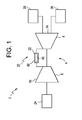
FIG. 1 depicts a turbomachine system including a turbomachine having a surface including a plurality of turbulators formed in accordance with an exemplary embodiment; -
FIG. 2 depicts a combustor liner of the turbomachine ofFIG. 1 including the plurality of turbulators formed in accordance with an exemplary embodiment; -
FIG. 3 depicts a first portion of a turbulator formed in accordance with an exemplary embodiment; -
FIG. 4 depicts a second portion of a turbulator formed in accordance with an exemplary embodiment; -
FIG. 5 depicts a third portion of a turbulator formed in accordance with an exemplary embodiment; and -
FIG. 6 depicts a cross-sectional view of a turbulator formed in accordance with an exemplary embodiment. - The detailed description explains embodiments of the invention, together with advantages and features, by way of example with reference to the drawings.
- With initial reference to
FIG. 1 , a turbomachine system is indicated generally at 2.Turbomachine system 2 includes aturbomachine 4 having a compressor portion 6 connected to aturbine portion 8. Compressor portion 6 includes aninlet 10.Turbine portion 8 includes anoutlet 14. Acombustor assembly 20 fluidically connects compressor portion 6 andturbine portion 8.Combustor assembly 20 includes one ormore combustors 22.Turbomachine system 2 is further shown to include anintake system 24 fluidically connected toinlet 10 and aload 26 that may be operatively connected toturbine portion 8. It should be understood thatload 26 may also be connected to compressor portion 6. Anexhaust system 28 is fluidically connected tooutlet 14 ofturbine portion 8.Exhaust system 28 receives and conditions exhaust gases passing fromturbomachine 4. - Combustor 22 includes a
combustor liner 40. As shown inFIG. 2 ,combustor liner 40 extends from afirst end 44 to asecond end 46 through anintermediate portion 48 having anouter surface 50 and an inner surface (not separately labeled). In accordance with an exemplary embodiment, a plurality of turbulators, one of which is indicated at 60, are provided onouter surface 50.Turbulators 60 circumscribecombustor liner 40 and are formed from amaterial 64 deposited onouter surface 50. In accordance with an aspect of an exemplary embodiment,material 64 may be similar to a material used to formcombustor liner 40. In accordance with another aspect of an exemplary embodiment,material 64 may be different from the material used to formcombustor liner 40. More specifically, the particular type of material used to formturbulators 60 may vary depending upon desired flow conditioning characteristics. For example, a less expensive material having desirable material characteristics may be employed to realize a cost savings. - In further accordance with an exemplary embodiment,
material 64 may be embodied in a welding electrode shown as an electricallyconductive wire 68 that is deposited ontoouter surface 50 through a welding process. More specifically, electricallyconductive wire 68 may be a consumable electrode dispensed from a welding member shown in the form of a metal-inert-gas (MIG)gun 70 positioned proximate toouter surface 50. Alternatively,material 64 may be embodied in a non-consumable electrode such as TIG or plasma arc welding. In still further accordance with an aspect of an exemplary embodiment,combustor liner 40 is rotated about afirst axis 78 whilematerial 64 is deposited ontoouter surface 50. After forming one of the plurality ofturbulators 60,MIG gun 70 translates, along asecond axis 80, to form another of the plurality ofturbulators 60, as will be detailed more fully below.Second axis 80 is angled relative tofirst axis 78 and generally follows an outer profile (not separately labeled) ofcombustor liner 40. - As shown in
FIG. 3 ,turbulator 60 is formed by initially depositing afirst portion 90 or pool ofmaterial 64 ontoouter surface 50 forming a fusion interface orbond 92. Asecond portion 94 may be added or deposited ontofirst portion 90, forming a combined pool of material, as shown inFIG. 4 . Of course, it should be understood thatsecond portion 94 may not be needed depending upon a desired dimension ofturbulator 60.FIG. 5 depicts a third portion orpool 98 ofmaterial 64 being combined withfirst portion 90 andsecond portion 94 to formturbulator 60. In accordance with an exemplary embodiment,turbulator 60 is formed by combining one or more molten pools of material and includes acurvilinear profile 100, as shown inFIG. 6 . In the embodiment shown inFIG. 6 ,turbulator 60 may include a height of between about 0.025-inch to about 0.06-inch and a width of about 0.030-inch to about 0.150-inch. Further, curvilinear profile may have a contact angle of less than about 60°. - At this point it should be understood that the exemplary embodiments describe a method of adding one or more turbulators to a turbomachine surface. More specifically, in contrast to prior art processes in which material is removed or subtracted from a surface, the exemplary embodiments add material to a turbomachine surface to form one or more turbulators. The addition of material not only reduces or eliminates significant waste formed when employing machining techniques, but also reduces manufacturing time. Further, by adding material, the turbulators may be formed having a number of geometries previously unattainable, in a cost effective manner, through subtractive processes such as machining. It should also be appreciated that the number, size, shape and pattern of the turbulators may vary. For example, turbulator dimensions may vary depending on desired heat transfer characteristics. Further, while shown as being added to an outer surface of a combustor liner, turbulators may be formed on virtually any turbomachine surface including compressor surfaces and turbine surfaces.
- While the invention has been described in detail in connection with only a limited number of embodiments, it should be readily understood that the invention is not limited to such disclosed embodiments. Rather, the invention can be modified to incorporate any number of variations, alterations, substitutions or equivalent arrangements not heretofore described, but which are commensurate with the spirit and scope of the invention. Additionally, while various embodiments of the invention have been described, it is to be understood that aspects of the invention may include only some of the described embodiments. Accordingly, the invention is not to be seen as limited by the foregoing description, but is only limited by the scope of the appended claims.
- Various aspects and embodiments of the present invention are defined by the following numbered clauses:
- 1. A method of forming a plurality of turbulators on a turbomachine surface comprising:
- depositing a portion of material on the turbomachine surface forming one of the plurality of turbulators.
- 2. The method of clause 1, further comprising:
- adding additional material to the portion of material; and
- establishing a desired dimension of the plurality of turbulators.
- 3. The method of any preceding clause, wherein establishing a desired dimension of the plurality of turbulators includes forming a curvilinear profile for each of the plurality of turbulators.
- 4. The method of any preceding clause, wherein depositing material on the turbomachine surface includes adding material to a combustor liner.
- 5. The method of any preceding clause, wherein depositing material on the turbomachine surface includes translating the turbomachine surface along a first axis relative to a welding member.
- 6. The method of any preceding clause, wherein translating the turbomachine surface along the first axis includes rotating the turbomachine surface.
- 7. The method of any preceding clause, further comprising: translating the welding member along a second axis distinct from the first axis.
- 8. The method of any preceding clause, wherein translating the welding member along the second axis includes moving the welding member along the second axis angled relative to the first axis.
- 9. The method of any preceding clause, wherein depositing material on the turbomachine surface includes directing a welding electrode toward the turbomachine surface.
- 10. The method of any preceding clause, wherein adding the additional material to the portion of material includes forming another portion of each of the plurality of turbulators that is smaller than the portion of material.
- 11. The method of any preceding clause, further comprising: adding a third portion to each of the plurality of turbulators that is smaller than the second portion.
- 12. The method of any preceding clause, wherein depositing material on the turbomachine surface includes depositing a material that is distinct from a material forming the turbomachine surface.
- 13. A turbomachine comprising:
- a compressor portion including a compressor surface;
- a turbine portion operatively connected to the compressor portion, the turbine portion including a turbine surface; and
- a combustor fluidically connected to the compressor portion and the turbine portion, the combustor including a combustor surface,
- wherein at least one of the compressor surface, turbine surface, and combustor surface includes a plurality of turbulators, each of the plurality of turbulators being formed from material deposited onto at least one of the compressor surface, turbine surface, and combustor surface.
- 14. The turbomachine according to any preceding clause, wherein each of the plurality of turbulators includes a curvilinear profile.
- 15. The turbomachine according to any preceding clause, wherein each of the plurality of turbulators is formed from a material that is distinct from a material forming the at least one of the compressor surface, turbine surface, and combustor surface.
- 16. The turbomachine according to any preceding clause, wherein each of the plurality of turbulators is formed from a one or more layers deposited onto the at least one of the compressor surface, turbine surface, and combustor surface.
- 17. A turbomachine system comprising:
- a compressor portion including a compressor surface;
- an intake system fluidically connected to the compressor portion;
- a turbine portion operatively connected to the compressor portion, the turbine portion including a turbine surface;
- a load operatively connected to one of the compressor portion and the turbine portion; and
- a combustor fluidically connected to the compressor portion and the turbine portion, the combustor including a combustor surface,
- wherein at least one of the compressor surface, turbine surface, and combustor surface includes a plurality of turbulators, each of the plurality of turbulators being formed from material deposited onto at least one of the compressor surface, turbine surface, and combustor surface.
- 18. The turbomachine system according to any preceding clause, wherein each of the plurality of turbulators includes a curvilinear profile.
- 19. The turbomachine system according to any preceding clause, wherein each of the plurality of turbulators is formed from a material that is distinct from a material forming the at least one of the compressor surface, turbine surface, and combustor surface.
- 20. The turbomachine system according to any preceding clause, wherein each of the plurality of turbulators is formed from a one or more layers deposited onto the at least one of the compressor surface, turbine surface and combustor surface.
Claims (15)
- A method of forming a plurality of turbulators (60) on a turbomachine surface comprising:depositing a portion of material on the turbomachine surface forming one of the plurality of turbulators (60).
- The method of claim 1, further comprising:adding additional material (64) to the portion of material; andestablishing a desired dimension of the plurality of turbulators (60).
- The method of claim 1 or claim 2, wherein establishing a desired dimension of the plurality of turbulators (60) includes forming a curvilinear profile (100) for each of the plurality of turbulators (60).
- The method of claim 1, 2 or 3, wherein depositing material (64) on the turbomachine surface includes adding material (64) to a combustor liner (40).
- The method of any of claims 1 to 4, wherein depositing material (64) on the turbomachine surface includes translating the turbomachine surface along a first axis (78) relative to a welding member.
- The method of claim 5, wherein translating the turbomachine surface along the first axis (78) includes rotating the turbomachine surface.
- The method of claim 5, further comprising: translating the welding member along a second axis (80) distinct from the first axis (78).
- The method of claim 7, wherein translating the welding member along the second axis (80) includes moving the welding member along the second axis (80) angled relative to the first axis (78).
- The method of any of claims 1 to 8, wherein depositing material (64) on the turbomachine surface includes directing a welding electrode toward the turbomachine surface.
- The method of any of claims 1 to 9, wherein adding the additional material (64) to the portion (90) of material includes forming another portion (94) of each of the plurality of turbulators (60) that is smaller than the portion of material.
- The method of claim 10, further comprising: adding a third portion (98) to each of the plurality of turbulators (60) that is smaller than the second portion (94).
- The method of any of claims 1 to 11, wherein depositing material (64) on the turbomachine surface includes depositing a material (64) that is distinct from a material forming the turbomachine surface.
- A turbomachine (4) comprising:a compressor portion (6) including a compressor surface;a turbine portion (8) operatively connected to the compressor portion (6), the turbine portion (8) including a turbine surface; anda combustor (22) fluidically connected to the compressor portion (6) and the turbine portion (8), the combustor (22) including a combustor surface,wherein at least one of the compressor surface, turbine surface, and combustor surface includes a plurality of turbulators (60), each of the plurality of turbulators (60) being formed from material (64) deposited onto at least one of the compressor surface, turbine surface, and combustor surface.
- The turbomachine (4) according to claim 13, wherein each of the plurality of turbulators (60) includes a curvilinear profile (100).
- The turbomachine (4) according to claim 13 or 14, wherein each of the plurality of turbulators (60) is formed from a material (64) that is distinct from a material forming the at least one of the compressor surface, turbine surface, and combustor surface.
Applications Claiming Priority (1)
| Application Number | Priority Date | Filing Date | Title |
|---|---|---|---|
| US14/522,824 US20160115799A1 (en) | 2014-10-24 | 2014-10-24 | Method of forming turbulators on a turbomachine surface and apparatus |
Publications (2)
| Publication Number | Publication Date |
|---|---|
| EP3015211A1 true EP3015211A1 (en) | 2016-05-04 |
| EP3015211B1 EP3015211B1 (en) | 2017-12-13 |
Family
ID=54359787
Family Applications (1)
| Application Number | Title | Priority Date | Filing Date |
|---|---|---|---|
| EP15190113.9A Active EP3015211B1 (en) | 2014-10-24 | 2015-10-16 | Method of forming tubulators on a turbomachine surface using build-up welding and corresponding turbomachine |
Country Status (4)
| Country | Link |
|---|---|
| US (1) | US20160115799A1 (en) |
| EP (1) | EP3015211B1 (en) |
| JP (1) | JP2016084806A (en) |
| CN (1) | CN105545488B (en) |
Families Citing this family (1)
| Publication number | Priority date | Publication date | Assignee | Title |
|---|---|---|---|---|
| US11306918B2 (en) * | 2018-11-02 | 2022-04-19 | Chromalloy Gas Turbine Llc | Turbulator geometry for a combustion liner |
Citations (4)
| Publication number | Priority date | Publication date | Assignee | Title |
|---|---|---|---|---|
| FR2498965A1 (en) * | 1981-02-04 | 1982-08-06 | Geneve Jacques | Producing rough non-slip surfaces on metal - by consumable electrode arc welding |
| US6116016A (en) * | 1996-09-09 | 2000-09-12 | Kabushiki Kaisha Toshiba | Gas turbine apparatus using fuel containing vanadium |
| US20090139291A1 (en) * | 2007-11-29 | 2009-06-04 | Metso Lokomo Steels Oy | Method for manufacturing a coiler drum and a coiler drum |
| US20120060504A1 (en) * | 2010-09-13 | 2012-03-15 | General Electric Company | Apparatus and method for cooling a combustor |
Family Cites Families (9)
| Publication number | Priority date | Publication date | Assignee | Title |
|---|---|---|---|---|
| US3918622A (en) * | 1974-03-25 | 1975-11-11 | Bailey Meter Co | Metal bellows welder |
| JPS5932470Y2 (en) * | 1979-12-04 | 1984-09-11 | 三菱重工業株式会社 | Holder for cylindrical body welding |
| ES2120414T3 (en) * | 1991-01-21 | 1998-11-01 | Sulzer Hydro Ag | METHOD OF MANUFACTURE OF METAL PARTS BY A WELDING APPARATUS, AND APPARATUS FOR ITS REALIZATION. |
| US6468669B1 (en) * | 1999-05-03 | 2002-10-22 | General Electric Company | Article having turbulation and method of providing turbulation on an article |
| US7351290B2 (en) * | 2003-07-17 | 2008-04-01 | General Electric Company | Robotic pen |
| US20100034647A1 (en) * | 2006-12-07 | 2010-02-11 | General Electric Company | Processes for the formation of positive features on shroud components, and related articles |
| US7757492B2 (en) * | 2007-05-18 | 2010-07-20 | General Electric Company | Method and apparatus to facilitate cooling turbine engines |
| FR2931714B1 (en) * | 2008-05-30 | 2010-06-25 | Snecma | CONSTRUCTION OF A PART OF A METAL PIECE BY THE MIG PROCESS WITH CURRENT AND PULSED WIRE |
| US20120102916A1 (en) * | 2010-10-29 | 2012-05-03 | General Electric Company | Pulse Detonation Combustor Including Combustion Chamber Cooling Assembly |
-
2014
- 2014-10-24 US US14/522,824 patent/US20160115799A1/en not_active Abandoned
-
2015
- 2015-10-15 JP JP2015203320A patent/JP2016084806A/en active Pending
- 2015-10-16 EP EP15190113.9A patent/EP3015211B1/en active Active
- 2015-10-23 CN CN201510691558.3A patent/CN105545488B/en not_active Expired - Fee Related
Patent Citations (4)
| Publication number | Priority date | Publication date | Assignee | Title |
|---|---|---|---|---|
| FR2498965A1 (en) * | 1981-02-04 | 1982-08-06 | Geneve Jacques | Producing rough non-slip surfaces on metal - by consumable electrode arc welding |
| US6116016A (en) * | 1996-09-09 | 2000-09-12 | Kabushiki Kaisha Toshiba | Gas turbine apparatus using fuel containing vanadium |
| US20090139291A1 (en) * | 2007-11-29 | 2009-06-04 | Metso Lokomo Steels Oy | Method for manufacturing a coiler drum and a coiler drum |
| US20120060504A1 (en) * | 2010-09-13 | 2012-03-15 | General Electric Company | Apparatus and method for cooling a combustor |
Also Published As
| Publication number | Publication date |
|---|---|
| CN105545488B (en) | 2019-05-10 |
| JP2016084806A (en) | 2016-05-19 |
| CN105545488A (en) | 2016-05-04 |
| EP3015211B1 (en) | 2017-12-13 |
| US20160115799A1 (en) | 2016-04-28 |
Similar Documents
| Publication | Publication Date | Title |
|---|---|---|
| US11156099B2 (en) | Turbine engine airfoil with a modified leading edge | |
| US10233775B2 (en) | Engine component for a gas turbine engine | |
| CN107084004B (en) | Impact holes for turbine engine components | |
| US20170198587A1 (en) | Cooled article | |
| EP2753799B1 (en) | Nutreparatur einer rotordrahtdichtung | |
| JP4623463B2 (en) | How to repair and replace combustor liner panels | |
| US20170298743A1 (en) | Component for a turbine engine with a film-hole | |
| JP6334145B2 (en) | Method for providing a coated gas turbine component | |
| US8961111B2 (en) | Turbine and method for separating particulates from a fluid | |
| US10443395B2 (en) | Component for a turbine engine with a film hole | |
| CN110735664B (en) | Components for turbine engines with cooling holes | |
| EP3015211A1 (en) | Method of forming tubulators on a turbomachine surface using build-up welding and corresponding turbomachine | |
| US12129769B2 (en) | Erosion-shielded turbine blades and methods of manufacturing the same | |
| US10982855B2 (en) | Combustor cap assembly with cooling microchannels | |
| CN112483192B (en) | Nozzle assemblies for turbine engines | |
| EP3338938A1 (en) | Method for modifying a shroud and blade | |
| US10731486B2 (en) | Duct assembly and method of forming | |
| US20170335693A1 (en) | Engine component assembly | |
| US20160053999A1 (en) | Combustor for a gas turbomachine |
Legal Events
| Date | Code | Title | Description |
|---|---|---|---|
| PUAI | Public reference made under article 153(3) epc to a published international application that has entered the european phase |
Free format text: ORIGINAL CODE: 0009012 |
|
| AK | Designated contracting states |
Kind code of ref document: A1 Designated state(s): AL AT BE BG CH CY CZ DE DK EE ES FI FR GB GR HR HU IE IS IT LI LT LU LV MC MK MT NL NO PL PT RO RS SE SI SK SM TR |
|
| AX | Request for extension of the european patent |
Extension state: BA ME |
|
| 17P | Request for examination filed |
Effective date: 20161104 |
|
| RBV | Designated contracting states (corrected) |
Designated state(s): AL AT BE BG CH CY CZ DE DK EE ES FI FR GB GR HR HU IE IS IT LI LT LU LV MC MK MT NL NO PL PT RO RS SE SI SK SM TR |
|
| RIC1 | Information provided on ipc code assigned before grant |
Ipc: F23R 3/00 20060101ALI20170405BHEP Ipc: F01D 5/18 20060101ALI20170405BHEP Ipc: B23K 101/04 20060101ALN20170405BHEP Ipc: F01D 5/14 20060101ALI20170405BHEP Ipc: B23K 9/04 20060101ALI20170405BHEP Ipc: B23K 101/00 20060101ALN20170405BHEP Ipc: B23K 9/23 20060101ALI20170405BHEP Ipc: B23K 9/00 20060101AFI20170405BHEP |
|
| GRAP | Despatch of communication of intention to grant a patent |
Free format text: ORIGINAL CODE: EPIDOSNIGR1 |
|
| RIC1 | Information provided on ipc code assigned before grant |
Ipc: B23K 9/23 20060101ALI20170504BHEP Ipc: F23R 3/00 20060101ALI20170504BHEP Ipc: B23K 101/00 20060101ALN20170504BHEP Ipc: F01D 5/14 20060101ALI20170504BHEP Ipc: B23K 9/00 20060101AFI20170504BHEP Ipc: B23K 101/04 20060101ALN20170504BHEP Ipc: B23K 9/04 20060101ALI20170504BHEP Ipc: F01D 5/18 20060101ALI20170504BHEP |
|
| INTG | Intention to grant announced |
Effective date: 20170515 |
|
| GRAS | Grant fee paid |
Free format text: ORIGINAL CODE: EPIDOSNIGR3 |
|
| GRAA | (expected) grant |
Free format text: ORIGINAL CODE: 0009210 |
|
| REG | Reference to a national code |
Ref country code: GB Ref legal event code: FG4D |
|
| REG | Reference to a national code |
Ref country code: AT Ref legal event code: REF Ref document number: 953904 Country of ref document: AT Kind code of ref document: T Effective date: 20171215 Ref country code: CH Ref legal event code: EP |
|
| REG | Reference to a national code |
Ref country code: IE Ref legal event code: FG4D |
|
| REG | Reference to a national code |
Ref country code: DE Ref legal event code: R096 Ref document number: 602015006619 Country of ref document: DE |
|
| REG | Reference to a national code |
Ref country code: NL Ref legal event code: MP Effective date: 20171213 |
|
| REG | Reference to a national code |
Ref country code: LT Ref legal event code: MG4D |
|
| PG25 | Lapsed in a contracting state [announced via postgrant information from national office to epo] |
Ref country code: LT Free format text: LAPSE BECAUSE OF FAILURE TO SUBMIT A TRANSLATION OF THE DESCRIPTION OR TO PAY THE FEE WITHIN THE PRESCRIBED TIME-LIMIT Effective date: 20171213 Ref country code: NO Free format text: LAPSE BECAUSE OF FAILURE TO SUBMIT A TRANSLATION OF THE DESCRIPTION OR TO PAY THE FEE WITHIN THE PRESCRIBED TIME-LIMIT Effective date: 20180313 Ref country code: FI Free format text: LAPSE BECAUSE OF FAILURE TO SUBMIT A TRANSLATION OF THE DESCRIPTION OR TO PAY THE FEE WITHIN THE PRESCRIBED TIME-LIMIT Effective date: 20171213 Ref country code: SE Free format text: LAPSE BECAUSE OF FAILURE TO SUBMIT A TRANSLATION OF THE DESCRIPTION OR TO PAY THE FEE WITHIN THE PRESCRIBED TIME-LIMIT Effective date: 20171213 |
|
| REG | Reference to a national code |
Ref country code: AT Ref legal event code: MK05 Ref document number: 953904 Country of ref document: AT Kind code of ref document: T Effective date: 20171213 |
|
| PG25 | Lapsed in a contracting state [announced via postgrant information from national office to epo] |
Ref country code: LV Free format text: LAPSE BECAUSE OF FAILURE TO SUBMIT A TRANSLATION OF THE DESCRIPTION OR TO PAY THE FEE WITHIN THE PRESCRIBED TIME-LIMIT Effective date: 20171213 Ref country code: HR Free format text: LAPSE BECAUSE OF FAILURE TO SUBMIT A TRANSLATION OF THE DESCRIPTION OR TO PAY THE FEE WITHIN THE PRESCRIBED TIME-LIMIT Effective date: 20171213 Ref country code: BG Free format text: LAPSE BECAUSE OF FAILURE TO SUBMIT A TRANSLATION OF THE DESCRIPTION OR TO PAY THE FEE WITHIN THE PRESCRIBED TIME-LIMIT Effective date: 20180313 Ref country code: RS Free format text: LAPSE BECAUSE OF FAILURE TO SUBMIT A TRANSLATION OF THE DESCRIPTION OR TO PAY THE FEE WITHIN THE PRESCRIBED TIME-LIMIT Effective date: 20171213 Ref country code: GR Free format text: LAPSE BECAUSE OF FAILURE TO SUBMIT A TRANSLATION OF THE DESCRIPTION OR TO PAY THE FEE WITHIN THE PRESCRIBED TIME-LIMIT Effective date: 20180314 |
|
| PG25 | Lapsed in a contracting state [announced via postgrant information from national office to epo] |
Ref country code: NL Free format text: LAPSE BECAUSE OF FAILURE TO SUBMIT A TRANSLATION OF THE DESCRIPTION OR TO PAY THE FEE WITHIN THE PRESCRIBED TIME-LIMIT Effective date: 20171213 |
|
| PG25 | Lapsed in a contracting state [announced via postgrant information from national office to epo] |
Ref country code: SK Free format text: LAPSE BECAUSE OF FAILURE TO SUBMIT A TRANSLATION OF THE DESCRIPTION OR TO PAY THE FEE WITHIN THE PRESCRIBED TIME-LIMIT Effective date: 20171213 Ref country code: EE Free format text: LAPSE BECAUSE OF FAILURE TO SUBMIT A TRANSLATION OF THE DESCRIPTION OR TO PAY THE FEE WITHIN THE PRESCRIBED TIME-LIMIT Effective date: 20171213 Ref country code: CY Free format text: LAPSE BECAUSE OF FAILURE TO SUBMIT A TRANSLATION OF THE DESCRIPTION OR TO PAY THE FEE WITHIN THE PRESCRIBED TIME-LIMIT Effective date: 20171213 Ref country code: CZ Free format text: LAPSE BECAUSE OF FAILURE TO SUBMIT A TRANSLATION OF THE DESCRIPTION OR TO PAY THE FEE WITHIN THE PRESCRIBED TIME-LIMIT Effective date: 20171213 Ref country code: ES Free format text: LAPSE BECAUSE OF FAILURE TO SUBMIT A TRANSLATION OF THE DESCRIPTION OR TO PAY THE FEE WITHIN THE PRESCRIBED TIME-LIMIT Effective date: 20171213 |
|
| PG25 | Lapsed in a contracting state [announced via postgrant information from national office to epo] |
Ref country code: RO Free format text: LAPSE BECAUSE OF FAILURE TO SUBMIT A TRANSLATION OF THE DESCRIPTION OR TO PAY THE FEE WITHIN THE PRESCRIBED TIME-LIMIT Effective date: 20171213 Ref country code: AT Free format text: LAPSE BECAUSE OF FAILURE TO SUBMIT A TRANSLATION OF THE DESCRIPTION OR TO PAY THE FEE WITHIN THE PRESCRIBED TIME-LIMIT Effective date: 20171213 Ref country code: PL Free format text: LAPSE BECAUSE OF FAILURE TO SUBMIT A TRANSLATION OF THE DESCRIPTION OR TO PAY THE FEE WITHIN THE PRESCRIBED TIME-LIMIT Effective date: 20171213 Ref country code: SM Free format text: LAPSE BECAUSE OF FAILURE TO SUBMIT A TRANSLATION OF THE DESCRIPTION OR TO PAY THE FEE WITHIN THE PRESCRIBED TIME-LIMIT Effective date: 20171213 Ref country code: IS Free format text: LAPSE BECAUSE OF FAILURE TO SUBMIT A TRANSLATION OF THE DESCRIPTION OR TO PAY THE FEE WITHIN THE PRESCRIBED TIME-LIMIT Effective date: 20180413 |
|
| REG | Reference to a national code |
Ref country code: DE Ref legal event code: R097 Ref document number: 602015006619 Country of ref document: DE |
|
| PLBE | No opposition filed within time limit |
Free format text: ORIGINAL CODE: 0009261 |
|
| STAA | Information on the status of an ep patent application or granted ep patent |
Free format text: STATUS: NO OPPOSITION FILED WITHIN TIME LIMIT |
|
| 26N | No opposition filed |
Effective date: 20180914 |
|
| PG25 | Lapsed in a contracting state [announced via postgrant information from national office to epo] |
Ref country code: DK Free format text: LAPSE BECAUSE OF FAILURE TO SUBMIT A TRANSLATION OF THE DESCRIPTION OR TO PAY THE FEE WITHIN THE PRESCRIBED TIME-LIMIT Effective date: 20171213 |
|
| PG25 | Lapsed in a contracting state [announced via postgrant information from national office to epo] |
Ref country code: SI Free format text: LAPSE BECAUSE OF FAILURE TO SUBMIT A TRANSLATION OF THE DESCRIPTION OR TO PAY THE FEE WITHIN THE PRESCRIBED TIME-LIMIT Effective date: 20171213 |
|
| REG | Reference to a national code |
Ref country code: CH Ref legal event code: PL |
|
| REG | Reference to a national code |
Ref country code: BE Ref legal event code: MM Effective date: 20181031 |
|
| PG25 | Lapsed in a contracting state [announced via postgrant information from national office to epo] |
Ref country code: LU Free format text: LAPSE BECAUSE OF NON-PAYMENT OF DUE FEES Effective date: 20181016 Ref country code: MC Free format text: LAPSE BECAUSE OF FAILURE TO SUBMIT A TRANSLATION OF THE DESCRIPTION OR TO PAY THE FEE WITHIN THE PRESCRIBED TIME-LIMIT Effective date: 20171213 |
|
| REG | Reference to a national code |
Ref country code: IE Ref legal event code: MM4A |
|
| PG25 | Lapsed in a contracting state [announced via postgrant information from national office to epo] |
Ref country code: BE Free format text: LAPSE BECAUSE OF NON-PAYMENT OF DUE FEES Effective date: 20181031 Ref country code: LI Free format text: LAPSE BECAUSE OF NON-PAYMENT OF DUE FEES Effective date: 20181031 Ref country code: FR Free format text: LAPSE BECAUSE OF NON-PAYMENT OF DUE FEES Effective date: 20181031 Ref country code: CH Free format text: LAPSE BECAUSE OF NON-PAYMENT OF DUE FEES Effective date: 20181031 |
|
| PG25 | Lapsed in a contracting state [announced via postgrant information from national office to epo] |
Ref country code: IE Free format text: LAPSE BECAUSE OF NON-PAYMENT OF DUE FEES Effective date: 20181016 |
|
| PG25 | Lapsed in a contracting state [announced via postgrant information from national office to epo] |
Ref country code: MT Free format text: LAPSE BECAUSE OF NON-PAYMENT OF DUE FEES Effective date: 20181016 |
|
| PG25 | Lapsed in a contracting state [announced via postgrant information from national office to epo] |
Ref country code: TR Free format text: LAPSE BECAUSE OF FAILURE TO SUBMIT A TRANSLATION OF THE DESCRIPTION OR TO PAY THE FEE WITHIN THE PRESCRIBED TIME-LIMIT Effective date: 20171213 |
|
| PG25 | Lapsed in a contracting state [announced via postgrant information from national office to epo] |
Ref country code: PT Free format text: LAPSE BECAUSE OF FAILURE TO SUBMIT A TRANSLATION OF THE DESCRIPTION OR TO PAY THE FEE WITHIN THE PRESCRIBED TIME-LIMIT Effective date: 20171213 |
|
| PG25 | Lapsed in a contracting state [announced via postgrant information from national office to epo] |
Ref country code: MK Free format text: LAPSE BECAUSE OF NON-PAYMENT OF DUE FEES Effective date: 20171213 Ref country code: HU Free format text: LAPSE BECAUSE OF FAILURE TO SUBMIT A TRANSLATION OF THE DESCRIPTION OR TO PAY THE FEE WITHIN THE PRESCRIBED TIME-LIMIT; INVALID AB INITIO Effective date: 20151016 |
|
| PG25 | Lapsed in a contracting state [announced via postgrant information from national office to epo] |
Ref country code: AL Free format text: LAPSE BECAUSE OF FAILURE TO SUBMIT A TRANSLATION OF THE DESCRIPTION OR TO PAY THE FEE WITHIN THE PRESCRIBED TIME-LIMIT Effective date: 20171213 |
|
| REG | Reference to a national code |
Ref country code: DE Ref legal event code: R081 Ref document number: 602015006619 Country of ref document: DE Owner name: GENERAL ELECTRIC TECHNOLOGY GMBH, CH Free format text: FORMER OWNER: GENERAL ELECTRIC COMPANY, SCHENECTADY, NY, US |
|
| REG | Reference to a national code |
Ref country code: GB Ref legal event code: 732E Free format text: REGISTERED BETWEEN 20240222 AND 20240228 |
|
| PGFP | Annual fee paid to national office [announced via postgrant information from national office to epo] |
Ref country code: IT Payment date: 20250923 Year of fee payment: 11 |
|
| PGFP | Annual fee paid to national office [announced via postgrant information from national office to epo] |
Ref country code: GB Payment date: 20250923 Year of fee payment: 11 |
|
| PGFP | Annual fee paid to national office [announced via postgrant information from national office to epo] |
Ref country code: DE Payment date: 20250923 Year of fee payment: 11 |