EP3015194A1 - Method for manufacturing cylinder block - Google Patents
Method for manufacturing cylinder block Download PDFInfo
- Publication number
- EP3015194A1 EP3015194A1 EP15191205.2A EP15191205A EP3015194A1 EP 3015194 A1 EP3015194 A1 EP 3015194A1 EP 15191205 A EP15191205 A EP 15191205A EP 3015194 A1 EP3015194 A1 EP 3015194A1
- Authority
- EP
- European Patent Office
- Prior art keywords
- pressure
- pressure pin
- cylinder block
- molten metal
- manufacturing
- Prior art date
- Legal status (The legal status is an assumption and is not a legal conclusion. Google has not performed a legal analysis and makes no representation as to the accuracy of the status listed.)
- Withdrawn
Links
- 238000004519 manufacturing process Methods 0.000 title claims abstract description 37
- 238000000034 method Methods 0.000 title claims description 37
- 229910052751 metal Inorganic materials 0.000 claims abstract description 55
- 239000002184 metal Substances 0.000 claims abstract description 55
- 238000002474 experimental method Methods 0.000 description 14
- 230000015572 biosynthetic process Effects 0.000 description 13
- 238000007711 solidification Methods 0.000 description 8
- 230000008023 solidification Effects 0.000 description 8
- 238000005336 cracking Methods 0.000 description 6
- 230000006872 improvement Effects 0.000 description 5
- 230000008569 process Effects 0.000 description 5
- 238000005266 casting Methods 0.000 description 4
- 230000000694 effects Effects 0.000 description 4
- 238000003754 machining Methods 0.000 description 4
- 229910000838 Al alloy Inorganic materials 0.000 description 2
- 238000004512 die casting Methods 0.000 description 2
- 239000000314 lubricant Substances 0.000 description 2
- 238000012986 modification Methods 0.000 description 2
- 230000004048 modification Effects 0.000 description 2
- 229910001018 Cast iron Inorganic materials 0.000 description 1
- 238000005299 abrasion Methods 0.000 description 1
- 230000008859 change Effects 0.000 description 1
- 238000002485 combustion reaction Methods 0.000 description 1
- 230000000052 comparative effect Effects 0.000 description 1
- 239000002826 coolant Substances 0.000 description 1
- 230000002950 deficient Effects 0.000 description 1
- 230000006866 deterioration Effects 0.000 description 1
- 238000009826 distribution Methods 0.000 description 1
- 230000005484 gravity Effects 0.000 description 1
- 238000005192 partition Methods 0.000 description 1
- 238000009751 slip forming Methods 0.000 description 1
- XLYOFNOQVPJJNP-UHFFFAOYSA-N water Substances O XLYOFNOQVPJJNP-UHFFFAOYSA-N 0.000 description 1
Images




Classifications
-
- B—PERFORMING OPERATIONS; TRANSPORTING
- B22—CASTING; POWDER METALLURGY
- B22D—CASTING OF METALS; CASTING OF OTHER SUBSTANCES BY THE SAME PROCESSES OR DEVICES
- B22D17/00—Pressure die casting or injection die casting, i.e. casting in which the metal is forced into a mould under high pressure
- B22D17/20—Accessories: Details
- B22D17/22—Dies; Die plates; Die supports; Cooling equipment for dies; Accessories for loosening and ejecting castings from dies
-
- B—PERFORMING OPERATIONS; TRANSPORTING
- B22—CASTING; POWDER METALLURGY
- B22D—CASTING OF METALS; CASTING OF OTHER SUBSTANCES BY THE SAME PROCESSES OR DEVICES
- B22D17/00—Pressure die casting or injection die casting, i.e. casting in which the metal is forced into a mould under high pressure
-
- B—PERFORMING OPERATIONS; TRANSPORTING
- B22—CASTING; POWDER METALLURGY
- B22D—CASTING OF METALS; CASTING OF OTHER SUBSTANCES BY THE SAME PROCESSES OR DEVICES
- B22D17/00—Pressure die casting or injection die casting, i.e. casting in which the metal is forced into a mould under high pressure
- B22D17/20—Accessories: Details
- B22D17/2015—Means for forcing the molten metal into the die
- B22D17/2069—Exerting after-pressure on the moulding material
-
- B—PERFORMING OPERATIONS; TRANSPORTING
- B22—CASTING; POWDER METALLURGY
- B22D—CASTING OF METALS; CASTING OF OTHER SUBSTANCES BY THE SAME PROCESSES OR DEVICES
- B22D17/00—Pressure die casting or injection die casting, i.e. casting in which the metal is forced into a mould under high pressure
- B22D17/20—Accessories: Details
-
- B—PERFORMING OPERATIONS; TRANSPORTING
- B22—CASTING; POWDER METALLURGY
- B22D—CASTING OF METALS; CASTING OF OTHER SUBSTANCES BY THE SAME PROCESSES OR DEVICES
- B22D25/00—Special casting characterised by the nature of the product
- B22D25/02—Special casting characterised by the nature of the product by its peculiarity of shape; of works of art
-
- F—MECHANICAL ENGINEERING; LIGHTING; HEATING; WEAPONS; BLASTING
- F02—COMBUSTION ENGINES; HOT-GAS OR COMBUSTION-PRODUCT ENGINE PLANTS
- F02F—CYLINDERS, PISTONS OR CASINGS, FOR COMBUSTION ENGINES; ARRANGEMENTS OF SEALINGS IN COMBUSTION ENGINES
- F02F7/00—Casings, e.g. crankcases
- F02F7/0043—Arrangements of mechanical drive elements
- F02F7/0053—Crankshaft bearings fitted in the crankcase
Definitions
- the present invention relates to a method for manufacturing a cylinder block, and in particular to a method for manufacturing a cylinder block of an engine for a vehicle.
- Japanese Unexamined Patent Application Publication No. 2012-179629 discloses a technique used in a method for manufacturing a die-cast article (i.e., a cylinder block) including a semicircular support surface on which a crankshaft is rotatably supported, in which a pressure is locally applied to molten metal located at or near the summit of the semicircular support surface by using a pressure pin. A pressure is applied to molten metal located in an area directly ahead of the pressure pin in its longitudinal direction by that pressure pin. As a result, the formation of blowholes in that area can be reduced.
- an oil flow channel extends from a main gallery toward the semicircular support surface so that a lubricant can be supplied to the crankshaft.
- this oil flow channel is connected to a bolt hole for attaching a crank cap due to the formation of a blowhole, an oil leak occurs, thus making the die-cast article defective. That is, there has been a problem that the yield of products deteriorates due to the formation of blowholes.
- the present invention has been made in view of the above-described problem and an object thereof is to reduce the formation of blowholes in a cylinder block better than the related art does and thereby to improve the yield of products.
- a first exemplary aspect of the present invention is a method for manufacturing a cylinder block including a semicircular bearing section that rotatably supports a crankshaft, the method including:
- the pressure pin whose tip protrudes in an arc shape so as to conform to the shape of the bearing section, is slid toward the area where the bearing section is formed in the step for applying a pressure to the molten metal. Therefore, the pressure applied to the molten metal is not only applied to the area located directly ahead of the pressure pin in its longitudinal direction but also applied radially from the center of the tip of the pressure pin. As a result, the formation of blowholes can be reduced in the entire area inside the cylinder block, thus leading to an improvement in the yield of products.
- the tip of the pressure pin is preferably formed in a semicircular shape. This structure can reduce the machining margin of the bearing section.
- the tip of the pressure pin is preferably formed in an arc shape shorter than a semicircle, and hence, in the pressure-injecting of the molten metal, no recess is formed in the boundary between the metal mold and the pressure pin. This structure can reduce deformations and cracking on the surface of the bearing section caused by microscopic solidification pieces.
- notches are formed on both edges of the tip of the pressure pin, which are in contact with the metal mold, so that the boundary between the metal mold and the pressure pin becomes flat without any difference in level formed therein in the pressure-injecting of the molten metal.
- This structure can reduce deformations and cracking on the surface of the bearing section caused by pulled-in solidification shells.
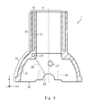
- Fig. 1 is a schematic bottom view of the cylinder block manufactured by the manufacturing method according to the first exemplary embodiment.
- Fig. 2 is a cross section taken along a line II-II in Fig. 1 .
- Fig. 3 is a cross section taken along a line III-III in Fig. 1 .
- the cylinder block 1 shown in Fig. 1 is a part of an inline four-cylinder engine in which four cylinder bores 11 each having an axis in parallel with the z-axis are arranged in the x-axis direction.
- the number of cylinders can be changed as desired.
- the present invention can also be applied to cylinder blocks of V-type engines and horizontally-opposed cylinder engines as well as inline engines.
- Figs. 1 to 3 the right-handed xyz-coordinate systems shown in Figs. 1 to 3 are shown just for the sake of convenience for explaining the positional relation among components.
- the cylinder block 1 is typically mounted on a vehicle in such a manner that the positive direction on the z-axis becomes the vertically upward direction. Therefore, the following explanation with reference to Figs. 1 to 3 is given on the assumption that the positive direction on the z-axis is the vertically upward direction.
- the cylinder block 1 is a die-cast article made of, for example, an aluminum alloy. As shown in Fig. 2 , the cylinder block 1 includes cylinder sections 10 with cylinder bores 11 formed therein, and skirt sections 20. The skirt sections form a part of a crank case that houses a crankshaft (not shown).
- a cylinder bore 11 which is a cylindrical hole, is formed in each of the cylinder sections 10.
- the part of the cylinder section 10 that surrounds the cylinder bore 11 is a cylinder wall 12.
- a piston (not shown), which performs a reciprocating motion inside the cylinder bore 11, is slid in the cylinder bore 11 while remaining in contact with the inner circumferential surface of the cylinder wall 12.
- a cylinder liner made of, for example, cast iron having an excellent wear resistance or the like is usually disposed on the inner circumferential surface of the cylinder wall 12 in order to reduce the abrasion caused by the sliding motion of the piston.
- a cylinder head (not shown) is mounted on the top end (end on the positive side on the z-axis) of the cylinder wall 12, i.e., on the so-called "upper deck". Further, the cylinder bore 11, the piston, and the cylinder head form a combustion chamber. A passage (water jacket) 13 through which a coolant is circulated is formed inside the cylinder wall 12, so that the cylinder section 10 can be cooled to an appropriate temperature.
- the skirt section 20 includes skirt walls 21 that form an outer shell of the crank case, and bulkheads 22 that partition the crank case into each cylinder bore 11.
- a pair of the skirt walls 21 are formed so that they seamlessly extend from the cylinder wall 12 and spread in the y-axis direction while being opposed to each other.
- a plurality of pairs of the skirt walls 21 are arranged in the x-axis direction.
- the bulkheads 22 are disposed in five places, i.e., between each pair of neighboring cylinder bores of the four cylinder bores 11 (three places) and both sides of the four cylinder bores 11 (two places).
- each of the bulkheads 22 extends in the y-axis direction so as to straddle a pair of the skirt walls 21.
- a semicircular bearing section 23 for rotatably supporting a journal (not shown) of the crankshaft is formed at the center of the bottom end (end on the negative side on the z-axis) of each bulkhead 22.
- Bolt holes 24 for attaching a crank cap (not shown) are formed on both sides of the bearing section 23.
- an oil flow channel 26 extends from a main gallery 25 toward the bearing section 23 inside each bulkhead 22.
- the main gallery 25 is disposed in one of the two connecting sections between the cylinder section 10 and the skirt section 20. Further, as shown in Fig. 1 , the main gallery 25 extends in the x-axis direction so as to intersect all of the bulkheads 22.
- the main gallery 25 is formed by using a core pin when the die-cast article is cast.
- the oil flow channel 26 is formed by machining after the casting process.
- a through hole 27 is formed near the center of each bulkhead 22.
- the through hole 27 is formed to connect the spaces partitioned by the bulkhead 22 with each other.
- the through hole 27 is formed by using a core pin when the die-cast article is cast.
- the through hole 27 may be formed by machining after the casting process.
- Fig. 4 is a schematic cross section showing a method for manufacturing a cylinder block according to the first exemplary embodiment.
- the cylinder block 1 is manufactured by die casting. Specifically, as shown in Fig. 4 , a movable mold (or movable die) 30 is moved in the positive direction on the z-axis and brought into contact with a fixed mold (or fixed die) 40. Then, molten metal is pressure-injected into a cavity 2 formed in a gap between these molds. As indicated by the xyz-coordinate system in Fig. 4 , the cylinder block 1 shown in Fig.
- the main gallery 25 is formed by using a core pin 50 that can be moved forward and backward in the x-axis direction, and the through hole 27 is formed by using another core pin 60 that can also be moved forward and backward in the x-axis direction.
- the bottom surface (surface on the negative side on the z-axis) of the bulkhead 22 of the cylinder block 1 is formed by the front surface (surface on the positive side on the z-axis) of the movable mold 30.
- pins 34 for forming rough holes (i.e., preparatory holes) for the bolt holes 24 are disposed on and protrude from the front surface of the movable mold 30. The pins 34 are fixed to the movable mold 30.
- a pressure pin 33 that can be slid in the z-axis direction with respect to the movable mold 30 is disposed in the movable mold 30.
- the pressure pin 33 forms the bearing section 23 of the bulkhead 22 and can apply a pressure to molten metal. It should be noted that in order to form the bearing section 23, the tip of the pressure pin 33 is formed so as to protrude in an arc shape to conform to the shape of the bearing section 23.
- the pressure pin 33 When molten metal is injected, the pressure pin 33 is positioned in a retreated position as indicated by a chain double-dashed line in Fig. 4 .
- the pressure pin 33 disposed in the movable mold 30 is slid forward (in the positive direction on the z-axis), i.e., is moved forward as indicated by a solid line in Fig. 4 , and a pressure is thereby applied to the molten metal. By doing so, the formation of blowholes inside the bulkhead 22 can be reduced.
- the sliding distance of the pressure pin 33 is, for example, in the order of several millimeters.
- a pressure pin whose tip is flat is slid toward an area where a bearing section is formed.
- the pressure pin 33 whose tip protrudes in an arc shape to conform to the shape of the bearing section 23, is slid toward the area where the bearing section 23 is formed. Therefore, the pressure applied to the molten metal is not only applied to the area located directly ahead of the pressure pin 33 in its longitudinal direction (i.e., the area located on the positive side on the z-axis) but also applied radially from the center of the tip of the pressure pin 33.
- the formation of blowholes can be reduced in the entire area inside the bulkhead 22, thus leading to an improvement in the yield of products.
- the tip of the pressure pin 33 protrudes in an arc shape to conform to the shape of the bearing section 23, the withdrawal resistance of the pressure pin 33.
- the bearing section 23 can be formed in a near net shape. That is, the maching margin (excess metal) of the bearing section 23 can be reduced, meaning that the productivity of this exemplary embodiment is superior to the relate art.
- the width of the pressure pin 33 is roughly equal to the diameter of the semicircular bearing section 23. That is, the tip of the pressure pin 33 is formed in a semicircular shape to conform to the shape of the bearing section 23. Therefore, the maching margin is significantly reduced.
- the pressure pin is moved forward with a sufficient maching margin.
- the related art requires more time in a subsequent machining process. Therefore, the productivity of the related art is inferior to that of this exemplary embodiment.
- the width w of the pressure pin 33 according to this exemplary embodiment is larger than that of a pressure pin in the related art. Provided that the amount of the volume change in the pressurization process in this exemplary embodiment is equal to that in the related art, the traveling distance of the pressure pin 33 can be reduced compared to that in the related art. As a result, the withdrawal resistance of the pressure pin 33 can be reduced.
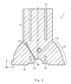
- FIG. 5 is a schematic cross section showing a method for manufacturing a cylinder block according to a second exemplary embodiment.
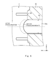
- Fig. 6 is an enlarged view of an area at or near the tip of the pressure pin 33 shown in Fig. 4 .
- a wedge-shaped recess is formed between the movable mold 30 and the pressure pin 33 before applying a pressure, i.e., in a state where the pressure pin 33 is in a retreated position. Since molten metal that has gotten into this recess solidifies quickly, microscopic solidification pieces are formed as shown in Fig. 6 . Then, when the pressure pin 33 is moved forward in the pressurization process, these microscopic solidification pieces could be pressed onto and buried into the surface of the bearing section 23 of the cylinder block 1, thus causing a possibility that deformations and cracking occur in the surface of the bearing section 23.
- the width w of a pressure pin 33a is a size smaller than that of the pressure pin 33 according to the first exemplary embodiment.
- the width of the pressure pin 33a is smaller than the diameter of the semicircular bearing section 23. That is, the tip of the pressure pin 33a is formed so as to have an arc shape shorter than a semicircle.
- This structure can reduce deformations and cracking on the surface of the bearing section 23 caused by microscopic solidification pieces because no recess is formed in the boundary between the movable mold 30 and the pressure pin 33a before the pressurization process.
- the width w of the pressure pin 33a is reduced, the maching margin could increase.
- Other configurations are similar to those in the first exemplary embodiment, and therefore their explanations are omitted.
- the method for manufacturing a cylinder block according to the second exemplary embodiment can reduce the formation of blowholes in the entire area inside the bulkhead 22, thus leading to an improvement in the yield of products.
- FIG. 7 is a schematic cross section showing a method for manufacturing a cylinder block according to a third exemplary embodiment.
- notches 35 are formed on both edges of the tip of a pressure pin 33b according to the third exemplary embodiment. In particular, these notches 35 are formed in areas of the tip that are in contact with the movable mold 30.
- the boundary between the movable mold 30 and the pressure pin 33b is flat without any difference in level formed therein before the pressurization process. Therefore, solidification shells that are continuously formed over the movable mold 30 and the pressure pin 33b can be easily sheared (i.e., cut) by moving the pressure pin 33b forward. As a result, deformations and cracking on the surface of the bearing section 23 caused by pulled-in solidification shells can be reduced even better than it is in the second exemplary embodiment. However, since the notches 35 are formed, the maching margin could increase.
- the method for manufacturing a cylinder block according to the third exemplary embodiment can reduce the formation of blowholes in the entire area inside the bulkhead 22, thus leading to an improvement in the yield of products.
- the second exemplary embodiment since no recess is formed between the movable mold 30 and the pressure pin 33b before the pressurizing process, deformations and cracking on the surface of the bearing section 23 caused by microscopic solidification pieces can be reduced (or prevented).
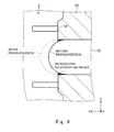
- FIG. 8 is a schematic cross section showing a method for manufacturing a cylinder block according to a fourth exemplary embodiment.
- a pressure pin 33c according to the fourth exemplary embodiment applies a pressure to the whole area where a crank cap is attached, instead of applying a pressure only to the area where the bearing section 23 is formed. Even when this configuration is employed, the formation of blowholes can be reduced (or prevented) in the entire area inside the bulkhead 22 as in the case of the first exemplary embodiment, thus leading to an improvement in the yield of products.
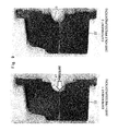
- Fig. 9 shows macro-photographs of ingots for explaining effects of pressurization for molten metal.
- Experiment examples 1 and 2 We have conducted the below-shown Experiment examples 1 and 2 to examine the effects of pressurization for molten metal. The experiment methods of Experiment examples 1 and 2 are explained hereinafter.
- Experiment example 1 corresponds to an example according to the present invention and Experiment example 2 corresponds to a comparative example.
- test piece was produced by die casting as an imitation of a bulkhead 22 of a cylinder block as shown in Fig. 9 by pressure-injecting molten metal of an aluminum alloy (ADC12) under a pressure of 25 MPa.
- ADC12 aluminum alloy
- the distribution state of blowholes in each of the test pieces was examined by observing its macro-structure. Further, the volume rate of the blowholes was obtained by measuring the specific gravity. Note that any of the bolt hole 24, the main gallery 25, and the through hole 27 was not formed in these test pieces.
- Casting was performed in the following manner: two seconds after molten metal was pressure-injected in a state where the pressure pin 33 was in a retreated position, the pressure pin 33 was moved forward by 4 mm and a pressure of 160 MPa was thereby applied to the molten metal.
- Casting was performed by pressure-injecting molten metal in a state where the pressure pin 33 was in a retreated position without moving the pressure pin 33.
- a method of manufacturing a cylinder block including a semicircular bearing section that rotatably supports a crankshaft includes pressure-injecting molten metal into a cavity formed inside a metal mold, and sliding a pressure pin disposed in the metal mold after the pressure-injecting of the molten metal and thereby applying a pressure to the molten metal injected in the cavity, in which in the applying of the pressure to the molten metal, the pressure pin is slid toward an area where the bearing section is formed, a tip of the pressure pin protruding in an arc shape so as to conform to a shape of the bearing section.
Landscapes
- Engineering & Computer Science (AREA)
- Mechanical Engineering (AREA)
- Molds, Cores, And Manufacturing Methods Thereof (AREA)
- Pistons, Piston Rings, And Cylinders (AREA)
- Cylinder Crankcases Of Internal Combustion Engines (AREA)
Abstract
A method of manufacturing a cylinder block including a semicircular bearing section that rotatably supports a crankshaft is provided. The method of manufacturing a cylinder block includes pressure-injecting molten metal into a cavity formed inside a metal mold, and sliding a pressure pin disposed in the metal mold after the pressure-injecting of the molten metal and thereby applying a pressure to the molten metal injected in the cavity, in which in the applying of the pressure to the molten metal, the pressure pin is slid toward an area where the bearing section is formed, a tip of the pressure pin protruding in an arc shape so as to conform to a shape of the bearing section.
Description
- The present invention relates to a method for manufacturing a cylinder block, and in particular to a method for manufacturing a cylinder block of an engine for a vehicle.
-
Japanese Unexamined Patent Application Publication No. 2012-179629 - However, the technique disclosed in
Japanese Unexamined Patent Application Publication No. 2012-179629 - The present invention has been made in view of the above-described problem and an object thereof is to reduce the formation of blowholes in a cylinder block better than the related art does and thereby to improve the yield of products.
- A first exemplary aspect of the present invention is a method for manufacturing a cylinder block including a semicircular bearing section that rotatably supports a crankshaft, the method including:
- pressure-injecting molten metal into a cavity formed inside a metal mold; and
- sliding a pressure pin disposed in the metal mold after the pressure-injecting of the molten metal and thereby applying a pressure to the molten metal injected in the cavity, in which
- in the applying of the pressure to the molten metal, the pressure pin is slid toward an area where the bearing section is formed, a tip of the pressure pin protruding in an arc shape so as to conform to a shape of the bearing section.
- In the method for manufacturing a cylinder block according to the above-described aspect of the present invention, the pressure pin, whose tip protrudes in an arc shape so as to conform to the shape of the bearing section, is slid toward the area where the bearing section is formed in the step for applying a pressure to the molten metal. Therefore, the pressure applied to the molten metal is not only applied to the area located directly ahead of the pressure pin in its longitudinal direction but also applied radially from the center of the tip of the pressure pin. As a result, the formation of blowholes can be reduced in the entire area inside the cylinder block, thus leading to an improvement in the yield of products.
- The tip of the pressure pin is preferably formed in a semicircular shape. This structure can reduce the machining margin of the bearing section.
- Further, the tip of the pressure pin is preferably formed in an arc shape shorter than a semicircle, and hence, in the pressure-injecting of the molten metal, no recess is formed in the boundary between the metal mold and the pressure pin. This structure can reduce deformations and cracking on the surface of the bearing section caused by microscopic solidification pieces.
- Further, notches are formed on both edges of the tip of the pressure pin, which are in contact with the metal mold, so that the boundary between the metal mold and the pressure pin becomes flat without any difference in level formed therein in the pressure-injecting of the molten metal. This structure can reduce deformations and cracking on the surface of the bearing section caused by pulled-in solidification shells.
- According to the present invention, it is possible to reduce the formation of blowholes in a cylinder block better than the related art does and thereby improve the yield of products.
- The above and other objects, features and advantages of the present invention will become more fully understood from the detailed description given hereinbelow and the accompanying drawings which are given by way of illustration only, and thus are not to be considered as limiting the present invention.
-
-
Fig. 1 is a schematic bottom view of a cylinder block manufactured by a manufacturing method according to a first exemplary embodiment; -
Fig. 2 is a cross section taken along a line II-II inFig. 1 ; -
Fig. 3 is a cross section taken along a line III-III inFig. 1 ; -
Fig. 4 is a schematic cross section showing a method for manufacturing a cylinder block according to the first exemplary embodiment; -
Fig. 5 is a schematic cross section showing a method for manufacturing a cylinder block according to a second exemplary embodiment; -
Fig. 6 is an enlarged view of an area at or near the tip of apressure pin 33 shown inFig. 4 ; -
Fig. 7 is a schematic cross section showing a method for manufacturing a cylinder block according to a third exemplary embodiment; -
Fig. 8 is a schematic cross section showing a method for manufacturing a cylinder block according to a fourth exemplary embodiment; and -
Fig. 9 shows macro-photographs of ingots for explaining effects of pressurization for molten metal. - Specific exemplary embodiments to which the present invention is applied are explained hereinafter in detail with reference to the drawings. However, the present invention is not limited to exemplary embodiments shown below. Further, the following descriptions and the drawings are simplified as appropriate for clarifying the explanation.
- Firstly, a cylinder block manufactured by a manufacturing method according to a first exemplary embodiment is explained with reference to
Figs. 1 to 3 .Fig. 1 is a schematic bottom view of the cylinder block manufactured by the manufacturing method according to the first exemplary embodiment.Fig. 2 is a cross section taken along a line II-II inFig. 1 .Fig. 3 is a cross section taken along a line III-III inFig. 1 . Thecylinder block 1 shown inFig. 1 is a part of an inline four-cylinder engine in which fourcylinder bores 11 each having an axis in parallel with the z-axis are arranged in the x-axis direction. However, the number of cylinders can be changed as desired. Further, the present invention can also be applied to cylinder blocks of V-type engines and horizontally-opposed cylinder engines as well as inline engines. - Note that, needless to say, the right-handed xyz-coordinate systems shown in
Figs. 1 to 3 are shown just for the sake of convenience for explaining the positional relation among components. Thecylinder block 1 is typically mounted on a vehicle in such a manner that the positive direction on the z-axis becomes the vertically upward direction. Therefore, the following explanation with reference toFigs. 1 to 3 is given on the assumption that the positive direction on the z-axis is the vertically upward direction. - The
cylinder block 1 is a die-cast article made of, for example, an aluminum alloy. As shown inFig. 2 , thecylinder block 1 includescylinder sections 10 withcylinder bores 11 formed therein, andskirt sections 20. The skirt sections form a part of a crank case that houses a crankshaft (not shown). - As shown in
Fig. 1 , acylinder bore 11, which is a cylindrical hole, is formed in each of thecylinder sections 10. The part of thecylinder section 10 that surrounds thecylinder bore 11 is acylinder wall 12. A piston (not shown), which performs a reciprocating motion inside thecylinder bore 11, is slid in thecylinder bore 11 while remaining in contact with the inner circumferential surface of thecylinder wall 12. Though it is not shown in the figures, a cylinder liner made of, for example, cast iron having an excellent wear resistance or the like is usually disposed on the inner circumferential surface of thecylinder wall 12 in order to reduce the abrasion caused by the sliding motion of the piston. - A cylinder head (not shown) is mounted on the top end (end on the positive side on the z-axis) of the
cylinder wall 12, i.e., on the so-called "upper deck". Further, the cylinder bore 11, the piston, and the cylinder head form a combustion chamber. A passage (water jacket) 13 through which a coolant is circulated is formed inside thecylinder wall 12, so that thecylinder section 10 can be cooled to an appropriate temperature. - The
skirt section 20 includesskirt walls 21 that form an outer shell of the crank case, andbulkheads 22 that partition the crank case into each cylinder bore 11. As shown inFig. 2 , a pair of theskirt walls 21 are formed so that they seamlessly extend from thecylinder wall 12 and spread in the y-axis direction while being opposed to each other. Further, as shown inFig. 1 , a plurality of pairs of theskirt walls 21 are arranged in the x-axis direction. Thebulkheads 22 are disposed in five places, i.e., between each pair of neighboring cylinder bores of the four cylinder bores 11 (three places) and both sides of the four cylinder bores 11 (two places). As shown inFigs. 1 and2 , each of thebulkheads 22 extends in the y-axis direction so as to straddle a pair of theskirt walls 21. - A
semicircular bearing section 23 for rotatably supporting a journal (not shown) of the crankshaft is formed at the center of the bottom end (end on the negative side on the z-axis) of eachbulkhead 22. Bolt holes 24 for attaching a crank cap (not shown) are formed on both sides of thebearing section 23. - Further, to enable the journal to be supplied with a lubricant, an
oil flow channel 26 extends from amain gallery 25 toward the bearingsection 23 inside eachbulkhead 22. Note that as shown inFig. 2 , themain gallery 25 is disposed in one of the two connecting sections between thecylinder section 10 and theskirt section 20. Further, as shown inFig. 1 , themain gallery 25 extends in the x-axis direction so as to intersect all of thebulkheads 22. In this exemplary embodiment, themain gallery 25 is formed by using a core pin when the die-cast article is cast. In contrast to this, theoil flow channel 26 is formed by machining after the casting process. - Further, a through
hole 27 is formed near the center of eachbulkhead 22. The throughhole 27 is formed to connect the spaces partitioned by thebulkhead 22 with each other. In this exemplary embodiment, the throughhole 27 is formed by using a core pin when the die-cast article is cast. However, needless to say, the throughhole 27 may be formed by machining after the casting process. - It should be noted that if the
oil flow channel 26 is connected to thebolt hole 24 or the throughhole 27 inFig. 3 , for example, an oil leak failure occurs, thus leading to a deterioration in the yield of products. However, in thecylinder block 1 manufactured by the manufacturing method according to this exemplary embodiment, the formation of blowholes inside thebulkhead 22 is reduced better than it is in the related art. Therefore, the yield of products in the manufacturing method according to this exemplary embodiment is superior to that in the related art. - Next, a method for manufacturing a cylinder block according to the first exemplary embodiment is explained with reference to
Fig. 4. Fig. 4 is a schematic cross section showing a method for manufacturing a cylinder block according to the first exemplary embodiment. Thecylinder block 1 is manufactured by die casting. Specifically, as shown inFig. 4 , a movable mold (or movable die) 30 is moved in the positive direction on the z-axis and brought into contact with a fixed mold (or fixed die) 40. Then, molten metal is pressure-injected into acavity 2 formed in a gap between these molds. As indicated by the xyz-coordinate system inFig. 4 , thecylinder block 1 shown inFig. 4 is rotated by 90° with respect to thecylinder block 1 shown inFig. 3 . InFig. 4 , the positive direction on the y-axis corresponds to the vertically upward direction. Themain gallery 25 is formed by using acore pin 50 that can be moved forward and backward in the x-axis direction, and the throughhole 27 is formed by using anothercore pin 60 that can also be moved forward and backward in the x-axis direction. - As shown in
Fig. 4 , the bottom surface (surface on the negative side on the z-axis) of thebulkhead 22 of thecylinder block 1 is formed by the front surface (surface on the positive side on the z-axis) of themovable mold 30. Note that pins 34 for forming rough holes (i.e., preparatory holes) for the bolt holes 24 are disposed on and protrude from the front surface of themovable mold 30. Thepins 34 are fixed to themovable mold 30. - Further, as shown in
Fig. 4 , apressure pin 33 that can be slid in the z-axis direction with respect to themovable mold 30 is disposed in themovable mold 30. Thepressure pin 33 forms the bearingsection 23 of thebulkhead 22 and can apply a pressure to molten metal. It should be noted that in order to form thebearing section 23, the tip of thepressure pin 33 is formed so as to protrude in an arc shape to conform to the shape of thebearing section 23. - When molten metal is injected, the
pressure pin 33 is positioned in a retreated position as indicated by a chain double-dashed line inFig. 4 . When the molten metal starts to solidify, thepressure pin 33 disposed in themovable mold 30 is slid forward (in the positive direction on the z-axis), i.e., is moved forward as indicated by a solid line inFig. 4 , and a pressure is thereby applied to the molten metal. By doing so, the formation of blowholes inside thebulkhead 22 can be reduced. The sliding distance of thepressure pin 33 is, for example, in the order of several millimeters. - It should be noted that in the related art, a pressure pin whose tip is flat is slid toward an area where a bearing section is formed. In contrast to this, in this exemplary embodiment, the
pressure pin 33, whose tip protrudes in an arc shape to conform to the shape of thebearing section 23, is slid toward the area where the bearingsection 23 is formed. Therefore, the pressure applied to the molten metal is not only applied to the area located directly ahead of thepressure pin 33 in its longitudinal direction (i.e., the area located on the positive side on the z-axis) but also applied radially from the center of the tip of thepressure pin 33. As a result, the formation of blowholes can be reduced in the entire area inside thebulkhead 22, thus leading to an improvement in the yield of products. - Further, since the tip of the
pressure pin 33 protrudes in an arc shape to conform to the shape of thebearing section 23, the withdrawal resistance of thepressure pin 33. Further, the bearingsection 23 can be formed in a near net shape. That is, the maching margin (excess metal) of thebearing section 23 can be reduced, meaning that the productivity of this exemplary embodiment is superior to the relate art. - In particular, in the first exemplary embodiment, the width of the
pressure pin 33 is roughly equal to the diameter of thesemicircular bearing section 23. That is, the tip of thepressure pin 33 is formed in a semicircular shape to conform to the shape of thebearing section 23. Therefore, the maching margin is significantly reduced. In the related art, the pressure pin is moved forward with a sufficient maching margin. Thus, compared to this exemplary embodiment, the related art requires more time in a subsequent machining process. Therefore, the productivity of the related art is inferior to that of this exemplary embodiment. - Further, the width w of the
pressure pin 33 according to this exemplary embodiment is larger than that of a pressure pin in the related art. Provided that the amount of the volume change in the pressurization process in this exemplary embodiment is equal to that in the related art, the traveling distance of thepressure pin 33 can be reduced compared to that in the related art. As a result, the withdrawal resistance of thepressure pin 33 can be reduced. - Next, a method for manufacturing a cylinder block according to a second exemplary embodiment is explained with reference to
Fig. 5. Fig. 5 is a schematic cross section showing a method for manufacturing a cylinder block according to a second exemplary embodiment. Firstly, a problem in the first exemplary embodiment is explained with reference toFig. 6. Fig. 6 is an enlarged view of an area at or near the tip of thepressure pin 33 shown inFig. 4 . - As shown in
Fig. 6 , in the method for manufacturing a cylinder block according to the first exemplary embodiment, a wedge-shaped recess is formed between themovable mold 30 and thepressure pin 33 before applying a pressure, i.e., in a state where thepressure pin 33 is in a retreated position. Since molten metal that has gotten into this recess solidifies quickly, microscopic solidification pieces are formed as shown inFig. 6 . Then, when thepressure pin 33 is moved forward in the pressurization process, these microscopic solidification pieces could be pressed onto and buried into the surface of thebearing section 23 of thecylinder block 1, thus causing a possibility that deformations and cracking occur in the surface of thebearing section 23. - To cope with this problem, in the method for manufacturing a cylinder block according to the second exemplary embodiment, as shown in
Fig. 5 , the width w of apressure pin 33a is a size smaller than that of thepressure pin 33 according to the first exemplary embodiment. In other words, the width of thepressure pin 33a is smaller than the diameter of thesemicircular bearing section 23. That is, the tip of thepressure pin 33a is formed so as to have an arc shape shorter than a semicircle. - This structure can reduce deformations and cracking on the surface of the
bearing section 23 caused by microscopic solidification pieces because no recess is formed in the boundary between themovable mold 30 and thepressure pin 33a before the pressurization process. However, since the width w of thepressure pin 33a is reduced, the maching margin could increase. Other configurations are similar to those in the first exemplary embodiment, and therefore their explanations are omitted. Similarly to the first exemplary embodiment, the method for manufacturing a cylinder block according to the second exemplary embodiment can reduce the formation of blowholes in the entire area inside thebulkhead 22, thus leading to an improvement in the yield of products. - Next, a method for manufacturing a cylinder block according to a third exemplary embodiment is explained with reference to
Fig. 7. Fig. 7 is a schematic cross section showing a method for manufacturing a cylinder block according to a third exemplary embodiment. As shown inFig. 7 , when compared to thepressure pin 33a according to the second exemplary embodiment,notches 35 are formed on both edges of the tip of apressure pin 33b according to the third exemplary embodiment. In particular, thesenotches 35 are formed in areas of the tip that are in contact with themovable mold 30. - By this structure, the boundary between the
movable mold 30 and thepressure pin 33b is flat without any difference in level formed therein before the pressurization process. Therefore, solidification shells that are continuously formed over themovable mold 30 and thepressure pin 33b can be easily sheared (i.e., cut) by moving thepressure pin 33b forward. As a result, deformations and cracking on the surface of thebearing section 23 caused by pulled-in solidification shells can be reduced even better than it is in the second exemplary embodiment. However, since thenotches 35 are formed, the maching margin could increase. - Other configurations are similar to those in the first and second exemplary embodiments, and therefore their explanations are omitted. Similarly to the first exemplary embodiment, the method for manufacturing a cylinder block according to the third exemplary embodiment can reduce the formation of blowholes in the entire area inside the
bulkhead 22, thus leading to an improvement in the yield of products. Further, similarly to the second exemplary embodiment, since no recess is formed between themovable mold 30 and thepressure pin 33b before the pressurizing process, deformations and cracking on the surface of thebearing section 23 caused by microscopic solidification pieces can be reduced (or prevented). - Next, a method for manufacturing a cylinder block according to a fourth exemplary embodiment is explained with reference to
Fig. 8. Fig. 8 is a schematic cross section showing a method for manufacturing a cylinder block according to a fourth exemplary embodiment. As shown inFig. 8 , apressure pin 33c according to the fourth exemplary embodiment applies a pressure to the whole area where a crank cap is attached, instead of applying a pressure only to the area where the bearingsection 23 is formed. Even when this configuration is employed, the formation of blowholes can be reduced (or prevented) in the entire area inside thebulkhead 22 as in the case of the first exemplary embodiment, thus leading to an improvement in the yield of products. - Next, advantageous effects of the method for manufacturing a cylinder block according to the first exemplary embodiment are explained with reference to
Fig. 9. Fig. 9 shows macro-photographs of ingots for explaining effects of pressurization for molten metal. We have conducted the below-shown Experiment examples 1 and 2 to examine the effects of pressurization for molten metal. The experiment methods of Experiment examples 1 and 2 are explained hereinafter. Experiment example 1 corresponds to an example according to the present invention and Experiment example 2 corresponds to a comparative example. - In both experiment examples, a test piece was produced by die casting as an imitation of a
bulkhead 22 of a cylinder block as shown inFig. 9 by pressure-injecting molten metal of an aluminum alloy (ADC12) under a pressure of 25 MPa. The distribution state of blowholes in each of the test pieces was examined by observing its macro-structure. Further, the volume rate of the blowholes was obtained by measuring the specific gravity. Note that any of thebolt hole 24, themain gallery 25, and the throughhole 27 was not formed in these test pieces. - Casting was performed in the following manner: two seconds after molten metal was pressure-injected in a state where the
pressure pin 33 was in a retreated position, thepressure pin 33 was moved forward by 4 mm and a pressure of 160 MPa was thereby applied to the molten metal. - Casting was performed by pressure-injecting molten metal in a state where the
pressure pin 33 was in a retreated position without moving thepressure pin 33. - As seen from the observations of the macro-structures shown in
Fig. 9 , in the test piece in Experiment example 1, in which molten metal was pressurized, the number of blowholes was fewer and their sizes were smaller over the entire cross section than those in the test piece in Experiment example 2, in which molten metal was not pressurized. Further, the volume rate of the blowholes in the test piece in Experiment example 1 was 1.0%, while that in the test piece in Experiment example 2 was 3.5%. Based on these experiment results, it has been proved that the method of manufacturing a cylinder block according to the first exemplary embodiment can reduce the formation of blowholes in the entire area inside thebulkhead 22. - Note that the present invention is not limited to the above-described exemplary embodiments, and various modifications can be made without departing from the spirit and scope of the present invention.
- From the invention thus described, it will be obvious that the embodiments of the invention may be varied in many ways. Such variations are not to be regarded as a departure from the spirit and scope of the invention, and all such modifications as would be obvious to one skilled in the art are intended for inclusion within the scope of the following claims.
- A method of manufacturing a cylinder block including a semicircular bearing section that rotatably supports a crankshaft is provided. The method of manufacturing a cylinder block includes pressure-injecting molten metal into a cavity formed inside a metal mold, and sliding a pressure pin disposed in the metal mold after the pressure-injecting of the molten metal and thereby applying a pressure to the molten metal injected in the cavity, in which in the applying of the pressure to the molten metal, the pressure pin is slid toward an area where the bearing section is formed, a tip of the pressure pin protruding in an arc shape so as to conform to a shape of the bearing section.
Claims (4)
- A method for manufacturing a cylinder block comprising a semicircular bearing section that rotatably supports a crankshaft, the method comprising:pressure-injecting molten metal into a cavity formed inside a metal mold; andsliding a pressure pin disposed in the metal mold after the pressure-injecting of the molten metal and thereby applying a pressure to the molten metal injected in the cavity, whereinin the applying of the pressure to the molten metal, the pressure pin is slid toward an area where the bearing section is formed, a tip of the pressure pin protruding in an arc shape so as to conform to a shape of the bearing section.
- The method for manufacturing a cylinder block according to Claim 1, wherein the tip of the pressure pin is formed in a semicircular shape.
- The method for manufacturing a cylinder block according to Claim 1, wherein
the tip of the pressure pin is formed in an arc shape shorter than a semicircle, and
in the pressure-injecting of the molten metal, no recess is formed in a boundary between the metal mold and the pressure pin. - The method for manufacturing a cylinder block according to Claim 3, wherein
notches are formed on both edges of the tip of the pressure pin, which are in contact with the metal mold, and
in the pressure-injecting of the molten metal, the boundary between the metal mold and the pressure pin is flat without any difference in level formed therein.
Applications Claiming Priority (1)
| Application Number | Priority Date | Filing Date | Title |
|---|---|---|---|
| JP2014219541A JP2016083689A (en) | 2014-10-28 | 2014-10-28 | Production method of cylinder block |
Publications (1)
| Publication Number | Publication Date |
|---|---|
| EP3015194A1 true EP3015194A1 (en) | 2016-05-04 |
Family
ID=55083264
Family Applications (1)
| Application Number | Title | Priority Date | Filing Date |
|---|---|---|---|
| EP15191205.2A Withdrawn EP3015194A1 (en) | 2014-10-28 | 2015-10-23 | Method for manufacturing cylinder block |
Country Status (5)
| Country | Link |
|---|---|
| US (1) | US20160114386A1 (en) |
| EP (1) | EP3015194A1 (en) |
| JP (1) | JP2016083689A (en) |
| CN (1) | CN105537557A (en) |
| BR (1) | BR102015026804A2 (en) |
Cited By (1)
| Publication number | Priority date | Publication date | Assignee | Title |
|---|---|---|---|---|
| EP3789134A1 (en) | 2019-09-05 | 2021-03-10 | Nemak, S.A.B. de C.V. | Squeezing cast metal via wedge mechanism |
Families Citing this family (3)
| Publication number | Priority date | Publication date | Assignee | Title |
|---|---|---|---|---|
| GB2537674A (en) * | 2015-04-23 | 2016-10-26 | Gm Global Tech Operations Llc | Lightweight Internal Cobustion Engine With A Ferrous Reinforced Cylinder Block |
| JP6696893B2 (en) * | 2016-12-22 | 2020-05-20 | トヨタ自動車株式会社 | Camshaft support member |
| JP7581926B2 (en) * | 2021-02-01 | 2024-11-13 | トヨタ自動車株式会社 | Manufacturing method of cast or forged products with bonded inserts |
Citations (4)
| Publication number | Priority date | Publication date | Assignee | Title |
|---|---|---|---|---|
| JPS5568164A (en) * | 1978-11-17 | 1980-05-22 | Toyota Motor Corp | Die-casting method of cylinder block for engine |
| JPS6316848A (en) * | 1986-07-09 | 1988-01-23 | Honda Motor Co Ltd | Casting method for cylinder block made of al alloy |
| EP0465947A1 (en) * | 1990-06-28 | 1992-01-15 | Ube Industries, Ltd. | Method and apparatus for casting engine block |
| JP2012179629A (en) | 2011-03-01 | 2012-09-20 | Ryobi Ltd | Method for producing die-cast product |
Family Cites Families (2)
| Publication number | Priority date | Publication date | Assignee | Title |
|---|---|---|---|---|
| JP3808167B2 (en) * | 1997-05-01 | 2006-08-09 | Ykk株式会社 | Method and apparatus for manufacturing amorphous alloy molded article formed by pressure casting with mold |
| CN102909337A (en) * | 2012-11-05 | 2013-02-06 | 中钢集团洛阳耐火材料研究院有限公司 | Metal casting device |
-
2014
- 2014-10-28 JP JP2014219541A patent/JP2016083689A/en not_active Withdrawn
-
2015
- 2015-10-09 US US14/879,681 patent/US20160114386A1/en not_active Abandoned
- 2015-10-09 CN CN201510649789.8A patent/CN105537557A/en active Pending
- 2015-10-22 BR BR102015026804A patent/BR102015026804A2/en not_active IP Right Cessation
- 2015-10-23 EP EP15191205.2A patent/EP3015194A1/en not_active Withdrawn
Patent Citations (4)
| Publication number | Priority date | Publication date | Assignee | Title |
|---|---|---|---|---|
| JPS5568164A (en) * | 1978-11-17 | 1980-05-22 | Toyota Motor Corp | Die-casting method of cylinder block for engine |
| JPS6316848A (en) * | 1986-07-09 | 1988-01-23 | Honda Motor Co Ltd | Casting method for cylinder block made of al alloy |
| EP0465947A1 (en) * | 1990-06-28 | 1992-01-15 | Ube Industries, Ltd. | Method and apparatus for casting engine block |
| JP2012179629A (en) | 2011-03-01 | 2012-09-20 | Ryobi Ltd | Method for producing die-cast product |
Cited By (2)
| Publication number | Priority date | Publication date | Assignee | Title |
|---|---|---|---|---|
| EP3789134A1 (en) | 2019-09-05 | 2021-03-10 | Nemak, S.A.B. de C.V. | Squeezing cast metal via wedge mechanism |
| WO2021044331A1 (en) | 2019-09-05 | 2021-03-11 | Nemak. S.A.B. De C.V. | Squeezing cast metal via wedge mechanism |
Also Published As
| Publication number | Publication date |
|---|---|
| US20160114386A1 (en) | 2016-04-28 |
| BR102015026804A2 (en) | 2016-08-09 |
| CN105537557A (en) | 2016-05-04 |
| JP2016083689A (en) | 2016-05-19 |
Similar Documents
| Publication | Publication Date | Title |
|---|---|---|
| KR101962525B1 (en) | Device for producing a cylinder crankcase using the low-pressure or gravity casting method | |
| CN101547760B (en) | Casting mould for casting a cast part and use of such a casting mould | |
| EP3015194A1 (en) | Method for manufacturing cylinder block | |
| CN101548088B (en) | Cylinder block and method of manufacturing same | |
| MX2009000630A (en) | Method for producing a cast component with a cast-in pipe. | |
| US7921901B2 (en) | Sacrificial sleeves for die casting aluminum alloys | |
| US8136243B2 (en) | Method for producing a piston for an internal combustion engine and the thus produced piston | |
| US8347943B2 (en) | Diecasting tool arrangement | |
| US20060096567A1 (en) | Cast part for an internal combustion engine | |
| US7694661B2 (en) | Crankcase, method of casting a crankcase, and a multiple-cylinder four-cycle engine comprising the crankcase | |
| US20130000482A1 (en) | Sand Casting An Aluminum Diesel Piston With An As-Cast, Reentrant Combustion Bowl For Light Or Medium Duty Diesel Engines | |
| US8371363B2 (en) | Apparatus for die casting, the use of such an apparatus and method for die casting | |
| US8720528B2 (en) | Method and device for casting a piston for an internal combustion engine | |
| KR20140034068A (en) | Sand casting an aluminum diesel piston with an as-cast, reentrant combustion bowl for light or medium duty diesel engines | |
| US20190134704A1 (en) | Mold assembly and method for manufacturing metal castings | |
| US20060175033A1 (en) | Method for moulding light alloy cast parts, in particular cylinder blocks | |
| US8887794B2 (en) | Process and apparatus for casting a piston for an internal combustion engine | |
| JP2009262190A (en) | Die casting | |
| WO2008075491A1 (en) | Aluminum die cast product and process for manufacturing the same | |
| US11318530B1 (en) | Slides and expendable cores for high pressure die cast closed deck engine block | |
| JP6117575B2 (en) | Molding equipment for casting | |
| CN114833311B (en) | Hybrid cam Kong Shaxin with metal chill for cast aluminum cylinders | |
| US8276644B2 (en) | Mold and casting method using the mold and design method of the mold | |
| JP2010064129A (en) | Method for producing cylinder block and production device therefor | |
| KR20210010746A (en) | Dicast casting method |
Legal Events
| Date | Code | Title | Description |
|---|---|---|---|
| PUAI | Public reference made under article 153(3) epc to a published international application that has entered the european phase |
Free format text: ORIGINAL CODE: 0009012 |
|
| 17P | Request for examination filed |
Effective date: 20151023 |
|
| AK | Designated contracting states |
Kind code of ref document: A1 Designated state(s): AL AT BE BG CH CY CZ DE DK EE ES FI FR GB GR HR HU IE IS IT LI LT LU LV MC MK MT NL NO PL PT RO RS SE SI SK SM TR |
|
| AX | Request for extension of the european patent |
Extension state: BA ME |
|
| STAA | Information on the status of an ep patent application or granted ep patent |
Free format text: STATUS: REQUEST FOR EXAMINATION WAS MADE |
|
| STAA | Information on the status of an ep patent application or granted ep patent |
Free format text: STATUS: THE APPLICATION IS DEEMED TO BE WITHDRAWN |
|
| 18D | Application deemed to be withdrawn |
Effective date: 20161105 |