EP3015130A1 - Protective caps for use with medical fluid fittings, and related methods - Google Patents
Protective caps for use with medical fluid fittings, and related methods Download PDFInfo
- Publication number
- EP3015130A1 EP3015130A1 EP15192340.6A EP15192340A EP3015130A1 EP 3015130 A1 EP3015130 A1 EP 3015130A1 EP 15192340 A EP15192340 A EP 15192340A EP 3015130 A1 EP3015130 A1 EP 3015130A1
- Authority
- EP
- European Patent Office
- Prior art keywords
- thread
- fitting
- cap
- protective cap
- medical fluid
- Prior art date
- Legal status (The legal status is an assumption and is not a legal conclusion. Google has not performed a legal analysis and makes no representation as to the accuracy of the status listed.)
- Withdrawn
Links
Images





Classifications
-
- A—HUMAN NECESSITIES
- A61—MEDICAL OR VETERINARY SCIENCE; HYGIENE
- A61M—DEVICES FOR INTRODUCING MEDIA INTO, OR ONTO, THE BODY; DEVICES FOR TRANSDUCING BODY MEDIA OR FOR TAKING MEDIA FROM THE BODY; DEVICES FOR PRODUCING OR ENDING SLEEP OR STUPOR
- A61M39/00—Tubes, tube connectors, tube couplings, valves, access sites or the like, specially adapted for medical use
-
- A—HUMAN NECESSITIES
- A61—MEDICAL OR VETERINARY SCIENCE; HYGIENE
- A61M—DEVICES FOR INTRODUCING MEDIA INTO, OR ONTO, THE BODY; DEVICES FOR TRANSDUCING BODY MEDIA OR FOR TAKING MEDIA FROM THE BODY; DEVICES FOR PRODUCING OR ENDING SLEEP OR STUPOR
- A61M39/00—Tubes, tube connectors, tube couplings, valves, access sites or the like, specially adapted for medical use
- A61M39/20—Closure caps or plugs for connectors or open ends of tubes
-
- F—MECHANICAL ENGINEERING; LIGHTING; HEATING; WEAPONS; BLASTING
- F16—ENGINEERING ELEMENTS AND UNITS; GENERAL MEASURES FOR PRODUCING AND MAINTAINING EFFECTIVE FUNCTIONING OF MACHINES OR INSTALLATIONS; THERMAL INSULATION IN GENERAL
- F16L—PIPES; JOINTS OR FITTINGS FOR PIPES; SUPPORTS FOR PIPES, CABLES OR PROTECTIVE TUBING; MEANS FOR THERMAL INSULATION IN GENERAL
- F16L35/00—Special arrangements used in connection with end fittings of hoses, e.g. safety or protecting devices
-
- F—MECHANICAL ENGINEERING; LIGHTING; HEATING; WEAPONS; BLASTING
- F16—ENGINEERING ELEMENTS AND UNITS; GENERAL MEASURES FOR PRODUCING AND MAINTAINING EFFECTIVE FUNCTIONING OF MACHINES OR INSTALLATIONS; THERMAL INSULATION IN GENERAL
- F16L—PIPES; JOINTS OR FITTINGS FOR PIPES; SUPPORTS FOR PIPES, CABLES OR PROTECTIVE TUBING; MEANS FOR THERMAL INSULATION IN GENERAL
- F16L55/00—Devices or appurtenances for use in, or in connection with, pipes or pipe systems
- F16L55/10—Means for stopping flow in pipes or hoses
- F16L55/115—Caps
- F16L55/1152—Caps fixed by screwing or by means of a screw-threaded ring
-
- A—HUMAN NECESSITIES
- A61—MEDICAL OR VETERINARY SCIENCE; HYGIENE
- A61M—DEVICES FOR INTRODUCING MEDIA INTO, OR ONTO, THE BODY; DEVICES FOR TRANSDUCING BODY MEDIA OR FOR TAKING MEDIA FROM THE BODY; DEVICES FOR PRODUCING OR ENDING SLEEP OR STUPOR
- A61M5/00—Devices for bringing media into the body in a subcutaneous, intra-vascular or intramuscular way; Accessories therefor, e.g. filling or cleaning devices, arm-rests
- A61M5/178—Syringes
- A61M5/31—Details
- A61M2005/3103—Leak prevention means for distal end of syringes, i.e. syringe end for mounting a needle
- A61M2005/3104—Caps for syringes without needle
-
- A—HUMAN NECESSITIES
- A61—MEDICAL OR VETERINARY SCIENCE; HYGIENE
- A61M—DEVICES FOR INTRODUCING MEDIA INTO, OR ONTO, THE BODY; DEVICES FOR TRANSDUCING BODY MEDIA OR FOR TAKING MEDIA FROM THE BODY; DEVICES FOR PRODUCING OR ENDING SLEEP OR STUPOR
- A61M39/00—Tubes, tube connectors, tube couplings, valves, access sites or the like, specially adapted for medical use
- A61M39/10—Tube connectors; Tube couplings
- A61M2039/1083—Tube connectors; Tube couplings having a plurality of female connectors, e.g. Luer connectors
-
- A—HUMAN NECESSITIES
- A61—MEDICAL OR VETERINARY SCIENCE; HYGIENE
- A61M—DEVICES FOR INTRODUCING MEDIA INTO, OR ONTO, THE BODY; DEVICES FOR TRANSDUCING BODY MEDIA OR FOR TAKING MEDIA FROM THE BODY; DEVICES FOR PRODUCING OR ENDING SLEEP OR STUPOR
- A61M39/00—Tubes, tube connectors, tube couplings, valves, access sites or the like, specially adapted for medical use
- A61M39/10—Tube connectors; Tube couplings
- A61M39/16—Tube connectors; Tube couplings having provision for disinfection or sterilisation
- A61M39/165—Shrouds or protectors for aseptically enclosing the connector
Definitions
- the present invention relates generally to medical fluid fittings, and more particularly, to caps for protecting sealing surfaces on medical fluid fittings.
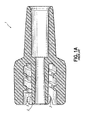
- FIG. 1A shows a cross-sectional view of a known male medical fluid fitting 1, including a male sealing portion 2 having a tapered sealing surface 3 for insertion into a mating component for forming a releasable seal with an inner surface thereof.
- FIG. 1A shows a cross-sectional view of a known male medical fluid fitting 1, including a male sealing portion 2 having a tapered sealing surface 3 for insertion into a mating component for forming a releasable seal with an inner surface thereof.
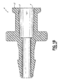
- FIG. 1B shows a cross-sectional view of a known female medical fluid fitting 4, including a female sealing portion 5 having a socket 6 and a tapered sealing surface 7 for receiving a mating component and forming a releasable seal with an outer surface thereof.
- the sealing portion is preferably fitted with a protective cap to maintain the sealing surface free from debris and damage from warping, scratching, galling, and other malformations caused by surface contact. In this manner, the sealing surface may be preserved for optimal sealing performance.
- the protective cap remains securely attached to the fitting such that the cap does not inadvertently detach from the fitting due to vibrations or impacts, such as those experienced during shipping and handling.
- Traditional caps rely on direct engagement with the sealing surface for maintaining a secure attachment to the fitting and retaining the cap in its protective position. However, such direct engagement may compromise the integrity of the sealing surface and thereby hinder the ability of the sealing surface to form an effective seal with a mating component during use.
- An exemplary embodiment of protective cap is provided for use with a medical fluid fitting that is configured to convey a fluid therethrough.
- the medical fluid fitting includes a fitting thread and a sealing portion having a sealing surface for forming a fluid tight seal with a mating part.
- the protective cap includes a body having a proximal end and a distal end, and a cap thread provided on the body and extending axially.
- the cap thread is configured to threadedly engage the fitting thread for releasably coupling the protective cap with the medical fluid fitting.
- the protective cap further includes a tapered engagement surface defined by the cap thread and tapering axially relative to a longitudinal axis of the body.
- the tapered engagement surface is configured to frictionally contact the fitting thread for retaining the protective cap in coupling engagement with the medical fluid fitting.
- the protective cap is configured to peripherally surround the sealing portion such that no portion of the protective cap contacts the sealing surface when the protective cap is coupled with the medical fluid fitting.
- An exemplary medical fluid fitting assembly includes a medical fluid fitting configured to convey a fluid therethrough.
- the medical fluid fitting includes a fitting thread and a sealing portion having a sealing surface for forming a fluid tight seal with a mating part.
- the medical fluid fitting assembly further includes a protective cap configured to protect the sealing surface of the medical fluid fitting.
- the protective cap includes a body having a proximal end and a distal end, and a cap thread provided on the body and extending axially.
- the cap thread is configured to threadedly engage the fitting thread for releasably coupling the protective cap with the medical fluid fitting.
- the protective cap further includes a tapered engagement surface defined by the cap thread and tapering axially relative to a longitudinal axis of the body. The tapered engagement surface is configured to frictionally contact the fitting thread for retaining the protective cap in coupling engagement with the medical fluid fitting.
- the protective cap peripherally surrounds the sealing portion without contacting the sealing surface when the protective cap is coupled with the medical fluid fitting.
- an exemplary method for protecting a sealing surface of a sealing portion of a medical fluid fitting, using a protective cap.
- the sealing surface is configured to form a fluid tight seal with a mating part so that fluid may pass through the medical fluid fitting.
- the method includes positioning a cap thread provided on a body of the protective cap in coaxial alignment with a fitting thread provided on the medical fluid fitting.
- the cap thread is threadedly engaged with the fitting thread to releasably couple the protective cap with the medical fluid fitting.
- the cap thread frictionally contacts the fitting thread to retain the protective cap in coupling engagement with the medical fluid fitting.
- the sealing portion of the medical fluid fitting is peripherally surrounded by the protective cap such that no portion of the protective cap contacts the sealing surface.
- a first exemplary embodiment of a male protective cap 10 is shown.
- the male protective cap 10 is adapted for use with a male medical fluid fitting 12 configured to convey fluids therethrough.
- the male fluid fitting includes a collar 14 and a stem 16 extending axially from the collar 14.
- the stem 16 is configured to be coupled to a medical conduit (not shown), such as a tubing, for forming a fluid-tight seal with the medical conduit so that fluid may pass through the conduit and into the fluid fitting 12.
- the stem 16 may include a tapered portion 18 for facilitating insertion of the stem into the medical conduit.
- the stem 16 may additionally include any suitable retention features, such as a barb (not shown), for retaining the stem 16 in coupling engagement with a medical conduit.
- the male fluid fitting 12 includes a male sealing portion 20, shown in the form of a tapered, nozzle-like protrusion, extending along a longitudinal axis of the male fluid fitting 12.
- the male sealing portion 20 defines a sealing surface 22, shown in the form of a tapered sealing surface, that is configured to form a fluid-tight seal with a mating female component (not shown).
- the sealing surface 22 may include a luer taper or any other suitable taper, for example.
- the male fluid fitting 12 is shown as having a tapered sealing surface 22, persons skilled in the art will appreciate that various embodiments of male protective caps may be adapted as appropriate for male fluid fittings having various types of sealing surfaces other than tapered sealing surfaces.
- the collar 14 of the male fluid fitting 12 circumferentially surrounds the male sealing portion 20 and includes a radially inner surface 24 that supports a helical fitting thread 26 which extends axially toward a base surface 28 of the sealing portion 20 (see FIG. 7 ).
- the fitting thread 26 is configured to threadedly engage a corresponding thread of a mating component (not shown). Additionally, the fitting thread 26 may be an overhauling thread that is configured to de-thread and separate from the corresponding thread of a mating component when opposing axial forces are applied to the fluid fitting 12 and the mating component.
- a radially outer surface 30 of the collar 14 may include one or more gripping features, shown in the form of longitudinal grooves 32, for aiding a user in gripping the fluid fitting during use, for example.
- the male protective cap 10 includes a base 34 and a tab 36 extending outwardly from the base 34 for facilitating manipulation of the protective cap 10 relative to the male fluid fitting 12.
- a radially outer surface 38 of the base 34 may include one or more gripping features, shown in the form of notches 40, which may generally correspond in width and depth to the grooves 32 on the fluid fitting 12, and may aid a user in gripping the protective cap 10 during use.
- a body 42 of the male protective cap 10 extends axially from the base 34 and includes a proximal end 44 and a distal end 46.
- the proximal end 44 includes a shoulder 48, which may include one or more cap vents 50 that extend radially through the shoulder 48 into a bore 52, shown in FIG. 6 , and cooperate with one or more fitting vents 54 formed on the fluid fitting 12, as described in greater below.
- the cap body 42 includes a helical cap thread 56 that extends axially toward the distal end 46. The cap thread 56 is configured to be threadedly engaged with the fitting thread 26 for releasably coupling the protective cap 10 with the fluid fitting 12.
- the cap thread 56 may be formed with a width that tapers circumferentially at a thread start 58 and at a thread end 60. Additionally, the cap thread 56 may be formed with one or more cut-out features 62, which may be included for facilitating removal of the cap 10 from a mold during an injection-molding process during manufacture, for example.
- protective caps of various embodiments include a tapered engagement surface defined by one of a root or a crest of the cap thread.
- the tapered engagement surface extends helically and tapers axially relative to a longitudinal axis of the cap body and is configured to frictionally engage a corresponding fitting thread on a medical fluid fitting for retaining the protective cap in coupling engagement with the medical fluid fitting.
- the cap thread 56 of the male protective cap 10 includes a thread root 64, a thread crest 66, and a tapered engagement surface 68 defined by the thread root 64.
- the body 42 of the male protective cap 10 includes a cylindrical wall 70 defining the bore 52 that extends axially from the distal end 46 to the proximal end 44 and into the base 34.
- the tapered engagement surface 68 is defined by the root 64 of the cap thread 56 and extends helically and tapers axially relative to the longitudinal axis of the cap body 42.
- the tapered surface 68 tapers from a large diameter at the proximal end 44 of the cap body 42 to a smaller diameter at the distal end 46 of the cap body 42.
- the tapered surface 68 may extend proximally beyond the thread end 60, up to the shoulder 48.
- an outer diameter defined by the crest 66 of the cap thread 56 remains substantially constant along an axial length of the cap thread 56. Accordingly, a thread height of the cap thread 56, defined by a radial distance between the thread root 64 and the thread crest 66, decreases proximally. Additionally, the tapered surface 68 may include a circumferential lead-in feature 74 at the distal end 46 for facilitating initial threaded engagement of the cap thread 56 with the fitting thread 26, as shown in FIG. 7 .
- the tapered engagement surface 68 tapers distally relative to the longitudinal axis of the cap body 42.
- the tapered surface 68 tapers with an included taper angle of approximately three degrees to approximately six degrees, and thus with a non-included taper angle ⁇ of approximately 1.5 degrees to approximately three degrees, as shown in FIG. 6 .
- Other embodiments of protective caps may also include tapered engagement surfaces that taper relative to a longitudinal axis of the corresponding cap body with an included taper angle of approximately three degrees to approximately six degrees, and a non-included taper angle ⁇ of approximately 1.5 degrees to approximately three degrees.
- the male protective cap 10 may be releasably coupled with the male fluid fitting 12 such that the cap body 42 peripherally surrounds the male sealing portion 20 without contacting the sealing surface 22.
- the protective cap 10 may shield the sealing surface 22 from unwanted contact with ambient elements and conditions.
- the externally-threaded cap body 42 is coaxially aligned with the internally-threaded fitting collar 14 and inserted therein such that the male sealing portion 20 is received within the bore 52 of the cap body 42.
- the protective cap 10 is rotated about its longitudinal axis, for example using the tab 36, so that cap thread 56 threadedly engages the fitting thread 26.
- the shoulder 48 of the cap body 42 may contact the radially inner surface 24 of the collar 14 to promote axial alignment of the protective cap 10 with the fluid fitting 12.
- a trailing side 76 of the cap thread 56 engages the fitting thread 26 to advance the distal end 46 of the cap body 42 axially toward the base surface 28 of the male sealing portion 20.
- the tapered engagement surface 68 defined by the root 64 of the cap thread 56 exerts a radial, outwardly-directed compressive force on, and thereby frictionally contacts, a thread crest 78 of the fitting thread 26.
- no portion of the cap thread 56 contacts a thread root 80 of the fitting thread 26, such that a radial gap is formed between the crest 66 of the cap thread 56 and the root 80 of the fitting thread 26.
- the radial compressive force exerted on the fitting thread 26 by the tapered surface 68 increases progressively as threaded engagement of the cap thread 56 and the fitting thread increases 26.
- the fitting thread 26 may be an overhauling-type thread, as described above, the threaded engagement between the fitting thread 26 and the cap thread 56 may be a non-overhauling-type engagement.
- the male protective cap 10 and the female fluid fitting 12 do not de-thread and separate from each other upon application of opposing axial forces on the protective cap 10 and the fluid fitting 12.
- the male fluid fitting 12 includes a first bore 84 extending through the male sealing portion 20, and a second bore 86 extending through the stem 16, the first and second bores 84, 86 being connected in fluidic communication to define a fluid flow path for conveying fluids.
- the cap vents 50 provided on the cap body 42 may extend and taper radially through the shoulder 48 and be arranged in fluidic communication with the cap bore 52. Accordingly, when the protective cap 10 is coupled with the fluid fitting 12, as shown in FIG. 7 , the cap vents 50 are positioned in fluidic communication with the fluid flow path on one side and with an ambient environment on another side, via the fitting vents 54 (see FIGS. 3-5 ). In this manner, gasses residing within the fluid flow path may be released through the cap vents 50 and the fitting vents 54 to an ambient environment.
- a first exemplary embodiment of a female protective cap 90 is shown.
- the female protective cap 90 is adapted for use with a female medical fluid fitting 92 configured to convey fluids therethrough.
- the female fluid fitting 92 includes a base 94 and a stem 96 extending axially from the base 94.
- a radially outer surface 97 of the base 94 may include one or more gripping features, shown in the form of notches 98, for aiding a user in gripping the fluid fitting 92 during use.
- the stem 96 is configured to be coupled to a medical conduit (not shown), such as a tubing, for forming a fluid-tight seal with the medical conduit so that fluid may pass through the conduit and into the fluid fitting.
- the stem 96 may include a barb 100 for retaining the stem 96 in coupling engagement with the medical conduit and forming a fluid-tight seal with the conduit.
- the female fluid fitting 92 includes a female sealing portion 102 extending axially from the base 94.
- the female sealing portion 102 includes a circumferential wall 104 and a fitting socket 106 extending along a longitudinal axis of the fluid fitting 92 and defining a sealing surface 108, shown in the form of a tapered sealing surface.
- the sealing surface 108 is configured to form a fluid-tight seal with a mating male component (not shown), and may include a luer taper or any other suitable taper, for example.
- various embodiments of female protective caps may be adapted as appropriate for female fluid fittings having various types of sealing surfaces other than tapered sealing surfaces.
- a radially outer portion of the circumferential wall 104 of the female sealing portion 102 includes a helical fitting thread 110 extending axially.
- the fitting thread 110 is configured to threadedly engage a corresponding thread of a mating component (not shown). Additionally, the fitting thread 110 may be an overhauling-type thread that it is configured to de-thread and separate from the corresponding thread of a mating component when opposing axial forces are applied to the mating component and the fluid fitting 92.
- the female protective cap 90 includes a body 112 having a proximal end 114 and a distal end 116.
- the body 112 includes a circumferential wall 118 that is integrally formed with an end wall 120 at the proximal end 114 and defines a cap socket 122 extending along a longitudinal axis of the body 112.
- a radially inner surface 124 of the circumferential wall 118 supports a helical cap thread 126 that extends axially from the distal end 116 toward the proximal end 114.
- the cap thread 126 may extend up to the end wall 120, for example.
- the cap thread 126 is configured to be threadedly engaged with the fitting thread 110 for releasably coupling the female protective cap 90 with the female fluid fitting 92, as described in greater detail below.
- a radially outer surface 128 of the cap body 112 may include one or more gripping features, shown in the form of longitudinal grooves 130, for aiding a user in gripping the protective cap 90 when coupling the cap 90 with the fluid fitting 92, described in greater detail below.
- the cap thread 126 of the female protective cap 90 includes a thread root 132, a thread crest 134, and a tapered engagement surface 136 defined by the thread root 132.
- the tapered engagement surface 136 extends helically and tapers proximally relative to the longitudinal axis of the body 112. As shown, the tapered surface 136 tapers from a large diameter at the distal end 116 of the cap body 112 to a smaller diameter at the proximal end 114 of the cap body 112.
- an inner diameter defined by the crest 134 of the cap thread 126 remains substantially constant along an axial length of the cap thread 126. Accordingly, a thread height of the cap thread 126, defined by a radial distance between the thread root 132 and the thread crest 134, decreases proximally.
- the tapered engagement surface 136 of the female protective cap 90 may taper with an included taper angle of approximately three degrees to approximately six degrees relative to the longitudinal axis of the cap body 112. Accordingly, as shown in FIG. 10 , the tapered surface 136 may taper with a non-included taper angle ⁇ of approximately 1.5 degrees to approximately three degrees relative to the cap body 112.
- the female protective cap 90 may be releasably coupled with the female fluid fitting 92 such that the cap body 112 peripherally surrounds the female sealing portion 102 without contacting the sealing surface 108. More specifically, the internally-threaded cap body 112 is coaxially aligned with the externally-threaded female sealing portion 102, which is received within the cap socket 122. The protective cap 90 is then rotated about its longitudinal axis, for example with the aid of grooves 130, to threadedly engage the cap thread 126 with the fitting thread 110.
- a trailing side 137 of the cap thread 126 engages the fitting thread 110 to advance the distal end 116 of the cap body 112 axially toward the base 94 of the female fluid fitting 92.
- the tapered engagement surface 136 defined by the root 132 of the cap thread 126 exerts a radial, inwardly-directed compressive force on, and thereby frictionally contacts, a crest 138 of the fitting thread 110.
- no portion of the cap thread 126 contacts a thread root 140 of the fitting thread 110, such that a radial gap is formed between the crest 134 of the cap thread and the root 140 of the fitting thread 110.
- the radial compressive force exerted on the fitting thread 110 by the tapered surface 136, for example by a proximal portion 142 thereof, increases progressively as threaded engagement of the cap thread 126 and the fitting thread 110 increases.
- the fitting thread 110 may be an overhauling-type thread, as described above, the threaded engagement between the fitting thread 110 and the cap thread 126 may be a non-overhauling-type engagement.
- the female protective cap 90 and the female fluid fitting 92 do not de-thread and separate from each other upon application of opposing axial forces on the protective cap 90 and the fluid fitting 92.
- first exemplary embodiments of male and female protective caps 10, 90 each including a tapered engagement surface 68, 136 defined by a root 64, 132 of the corresponding cap thread 56, 126.
- second exemplary embodiments of male and female protective caps 10a, 90a each including a tapered engagement surface 68a, 136a defined by a crest 66a, 134a of the corresponding cap thread 56a, 126a.
- FIGS. 12-14 a second exemplary embodiment of a male protective cap 10a is shown, for which similar reference numerals refer to similar features shown in FIGS. 2-7 .
- the male protective cap 10a may be adapted for use with the male medical fluid fitting 12, for example.
- the male protective cap 10a may be modified as appropriate for use with male medical fluid fittings having various types of sealing surfaces, including tapered sealing surfaces.
- a body 42a of the male protective cap 10a includes a helical cap thread 56a having a thread root 64a, a thread crest 66a, and a tapered engagement surface 68a defined by the thread crest 66a.
- An outer diameter defined by the crest 66a of the cap thread 56a increases proximally while a diameter defined by the root 64a of the cap thread 56a remains substantially constant along the axial length of the cap thread 56a. Accordingly, a thread height of the cap thread 56a, defined by a radial distance between the thread root 64a and the thread crest 66a, increases proximally.
- the tapered engagement surface 68a of male cap 10a tapers distally relative to the longitudinal axis of the cap body 42a.
- the tapered surface 68a tapers with an included taper angle of approximately three degrees to approximately six degrees, and with a non-included taper angle ⁇ of approximately 1.5 degrees to approximately three degrees, as shown in FIG. 13 .
- the male protective cap 10a may be releasably coupled to the male fluid fitting 12 such that the cap body 42a peripherally surrounds the male sealing portion 20 without contacting the sealing surface 22.
- the male cap 10a may be coaxially aligned and coupled with the male fluid fitting 12 in a manner similar to that described above in connection with the male cap 10 shown in FIG. 7 , such that the cap thread 56a threadedly engages the fitting thread 26.
- the tapered surface 68a defined by the crest 66a of the cap thread 56a exerts a radial, outwardly-directed compressive force on, and thereby frictionally contacts, the root 80 of the fitting thread 26.
- no portion of the cap thread 56a contacts the crest 78 of the fitting thread 26, such that a radial gap is formed between the root 64a of the cap thread 56a and the crest 78 of the fitting thread 26.
- the radial compressive force exerted on the fitting thread 26 by the tapered surface 68a increases progressively as threaded engagement of the cap thread 56a and the fitting thread 26 increases. In this manner, an interference fit is created between the cap thread 56a and the fitting thread 26, thereby retaining the protective cap 10a in coupling engagement with the fluid fitting 12.
- FIGS. 15-17 a second exemplary embodiment of a female protective cap 90a is shown, for which similar reference numerals refer to similar features shown in FIGS. 8-11 .
- the female protective cap 90a may be adapted for use with the female medical fluid fitting 92, for example.
- the female protective cap 90a may be modified as appropriate for use with female medical fluid fittings having various types of sealing surfaces, including tapered sealing surfaces.
- a body 112a of the female protective cap 90a includes a circumferential wall 118a having a radially inner surface 124a that supports a helical cap thread 126a.
- the cap thread 126a includes a thread root 132a, a thread crest 134a, and a tapered engagement surface 136a defined by the thread crest 134a.
- the tapered surface 136a tapers from a large diameter at the distal end 116a of the cap body 112a to a smaller diameter at the proximal end 114a of the cap body 112a.
- an inner diameter defined by the thread root 132a remains substantially constant along an axial length of the cap thread 126a. Accordingly, a thread height of the cap thread 126a, defined by a radial distance between the thread root 132a and the thread crest 134a, increases proximally.
- the tapered engagement surface 136a of female protective cap 90a tapers proximally relative to the longitudinal axis of the cap body 112a.
- the tapered surface 136 tapers with an included taper angle of approximately three degrees to approximately six degrees, and with a non-included taper angle ⁇ of approximately 1.5 degrees to approximately three degrees, as shown in FIG. 16 .
- the female protective cap 90a may be releasably coupled to the female fluid fitting 92 such that the cap body 112a peripherally surrounds the female sealing portion 102 without contacting the sealing surface 108.
- the female cap 90a may be coaxially aligned and coupled with the female fluid fitting 92 in a manner similar to that described above in connection with the female cap 90 shown in FIG. 11 , such that the cap thread 126a threadedly engages the fitting thread 110.
- the tapered surface 136a defined by the crest 134a of the cap thread 126a exerts a radial, inwardly-directed compressive force on, and thereby frictionally contacts, the root 140 of the fitting thread 110.
- no portion of the cap thread contacts the crest 138 of the fitting thread, such that a radial gap is formed between the root 132a of the cap thread 126a and the crest 138 of the fitting thread 110.
- the radial compressive force exerted on the fitting thread 110 by the tapered surface 136a, for example by a proximal portion 142a thereof, increases progressively as threaded engagement of the cap thread 126a and the fitting thread 110 increases. In this manner, an interference fit is created between the cap thread 126a and the fitting thread 110, thereby retaining the female protective cap 90a in coupling engagement with the female fluid fitting 92.
Landscapes
- Health & Medical Sciences (AREA)
- Engineering & Computer Science (AREA)
- Heart & Thoracic Surgery (AREA)
- General Engineering & Computer Science (AREA)
- Hematology (AREA)
- Pulmonology (AREA)
- Anesthesiology (AREA)
- Biomedical Technology (AREA)
- Life Sciences & Earth Sciences (AREA)
- Animal Behavior & Ethology (AREA)
- General Health & Medical Sciences (AREA)
- Public Health (AREA)
- Veterinary Medicine (AREA)
- Mechanical Engineering (AREA)
- Infusion, Injection, And Reservoir Apparatuses (AREA)
- Quick-Acting Or Multi-Walled Pipe Joints (AREA)
- Protection Of Pipes Against Damage, Friction, And Corrosion (AREA)
Abstract

Description
- The present invention relates generally to medical fluid fittings, and more particularly, to caps for protecting sealing surfaces on medical fluid fittings.
- Various types of fittings, or connectors, are often used for interconnecting conduit and other components in medical applications for conveying fluids. Such medical fluid fittings include a sealing portion having a sealing surface for forming a fluid-tight seal when mated with a corresponding sealing surface of a mating component, thereby ensuring reliable transfer of fluids. Such fittings and their corresponding sealing portions may be male or female. For example,
FIG. 1A shows a cross-sectional view of a known male medical fluid fitting 1, including a male sealing portion 2 having a taperedsealing surface 3 for insertion into a mating component for forming a releasable seal with an inner surface thereof.FIG. 1B shows a cross-sectional view of a known female medical fluid fitting 4, including a female sealing portion 5 having asocket 6 and a taperedsealing surface 7 for receiving a mating component and forming a releasable seal with an outer surface thereof. - When the sealing surface of a medical fluid fitting is not in use, the sealing portion is preferably fitted with a protective cap to maintain the sealing surface free from debris and damage from warping, scratching, galling, and other malformations caused by surface contact. In this manner, the sealing surface may be preserved for optimal sealing performance. Preferably, the protective cap remains securely attached to the fitting such that the cap does not inadvertently detach from the fitting due to vibrations or impacts, such as those experienced during shipping and handling. Traditional caps rely on direct engagement with the sealing surface for maintaining a secure attachment to the fitting and retaining the cap in its protective position. However, such direct engagement may compromise the integrity of the sealing surface and thereby hinder the ability of the sealing surface to form an effective seal with a mating component during use.
- An exemplary embodiment of protective cap is provided for use with a medical fluid fitting that is configured to convey a fluid therethrough. The medical fluid fitting includes a fitting thread and a sealing portion having a sealing surface for forming a fluid tight seal with a mating part. The protective cap includes a body having a proximal end and a distal end, and a cap thread provided on the body and extending axially. The cap thread is configured to threadedly engage the fitting thread for releasably coupling the protective cap with the medical fluid fitting. The protective cap further includes a tapered engagement surface defined by the cap thread and tapering axially relative to a longitudinal axis of the body. The tapered engagement surface is configured to frictionally contact the fitting thread for retaining the protective cap in coupling engagement with the medical fluid fitting. The protective cap is configured to peripherally surround the sealing portion such that no portion of the protective cap contacts the sealing surface when the protective cap is coupled with the medical fluid fitting.
- An exemplary medical fluid fitting assembly includes a medical fluid fitting configured to convey a fluid therethrough. The medical fluid fitting includes a fitting thread and a sealing portion having a sealing surface for forming a fluid tight seal with a mating part. The medical fluid fitting assembly further includes a protective cap configured to protect the sealing surface of the medical fluid fitting. The protective cap includes a body having a proximal end and a distal end, and a cap thread provided on the body and extending axially. The cap thread is configured to threadedly engage the fitting thread for releasably coupling the protective cap with the medical fluid fitting. The protective cap further includes a tapered engagement surface defined by the cap thread and tapering axially relative to a longitudinal axis of the body. The tapered engagement surface is configured to frictionally contact the fitting thread for retaining the protective cap in coupling engagement with the medical fluid fitting. The protective cap peripherally surrounds the sealing portion without contacting the sealing surface when the protective cap is coupled with the medical fluid fitting.
- In use, an exemplary method is provided for protecting a sealing surface of a sealing portion of a medical fluid fitting, using a protective cap. The sealing surface is configured to form a fluid tight seal with a mating part so that fluid may pass through the medical fluid fitting. The method includes positioning a cap thread provided on a body of the protective cap in coaxial alignment with a fitting thread provided on the medical fluid fitting. The cap thread is threadedly engaged with the fitting thread to releasably couple the protective cap with the medical fluid fitting. The cap thread frictionally contacts the fitting thread to retain the protective cap in coupling engagement with the medical fluid fitting. The sealing portion of the medical fluid fitting is peripherally surrounded by the protective cap such that no portion of the protective cap contacts the sealing surface.
- The invention will now be further described by way of example with reference to the accompanying drawings, in which:
-
FIG. 1A is a cross-sectional view showing a known male medical fluid fitting. -
FIG. 1B is a cross-sectional view showing a known female medical fluid fitting. -
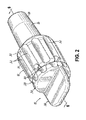
FIG. 2 is a perspective view showing a first embodiment of a male protective cap, assembled with a male medical fluid fitting. -
FIG. 3 is a perspective, disassembled view showing the male protective cap and male medical fluid fitting ofFIG. 2 . -
FIG. 4 is a side, disassembled view showing the male protective cap and male medical fluid fitting ofFIG. 2 . -
FIG. 5 is a top, disassembled view showing the male protective cap and male medical fluid fitting ofFIG. 2 . -
FIG. 6 is a cross-sectional view taken along line 6-6 ofFIG. 2 , showing the male protective cap. -
FIG. 7 is a cross-sectional view taken along line 6-6 ofFIG. 2 , showing the male protective cap assembled with the male medical fluid fitting. -
FIG. 8 is a perspective view showing a first embodiment of a female protective cap, assembled with a female medical fluid fitting. -
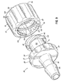
FIG. 9 is a perspective, disassembled view showing the female protective cap and female medical fluid fitting ofFIG. 8 . -
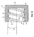
FIG. 10 is a cross-sectional view taken along line 10-10 ofFIG. 8 , showing the female protective cap. -
FIG. 11 is a cross-sectional view taken along line 10-10 ofFIG. 8 , showing the female protective cap assembled with the female medical fluid fitting. -
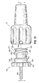
FIG. 12 is a side view showing a second embodiment of a male protective cap, disassembled from a male medical fluid fitting. -
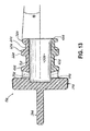
FIG. 13 is a cross-sectional view taken along line 13-13 ofFig. 12 , showing the male protective cap. -
FIG. 14 is a cross-sectional view taken along line 13-13 ofFIG. 12 , showing the male protective cap assembled with the male medical fluid fitting. -
FIG. 15 is a perspective view showing a second embodiment of a female protective cap, disassembled from a female medical fluid fitting. -
FIG. 16 is a cross-sectional view taken along line 16-16 ofFIG. 15 , showing the female protective cap. -
FIG. 17 is a cross-sectional view taken along line 16-16 ofFIG. 15 , showing the female protective cap assembled with the female medical fluid fitting. - Referring to
FIGS. 2-7 , a first exemplary embodiment of a maleprotective cap 10 is shown. The maleprotective cap 10 is adapted for use with a male medical fluid fitting 12 configured to convey fluids therethrough. As shown inFIG. 2 , the male fluid fitting includes acollar 14 and astem 16 extending axially from thecollar 14. Thestem 16 is configured to be coupled to a medical conduit (not shown), such as a tubing, for forming a fluid-tight seal with the medical conduit so that fluid may pass through the conduit and into the fluid fitting 12. Thestem 16 may include atapered portion 18 for facilitating insertion of the stem into the medical conduit. Thestem 16 may additionally include any suitable retention features, such as a barb (not shown), for retaining thestem 16 in coupling engagement with a medical conduit. - Referring to
FIGS. 3-5 , additional features of the maleprotective cap 10 and themale fluid fitting 12 are shown. Themale fluid fitting 12 includes amale sealing portion 20, shown in the form of a tapered, nozzle-like protrusion, extending along a longitudinal axis of the male fluid fitting 12. Themale sealing portion 20 defines asealing surface 22, shown in the form of a tapered sealing surface, that is configured to form a fluid-tight seal with a mating female component (not shown). The sealingsurface 22 may include a luer taper or any other suitable taper, for example. In this regard, although the male fluid fitting 12 is shown as having a tapered sealingsurface 22, persons skilled in the art will appreciate that various embodiments of male protective caps may be adapted as appropriate for male fluid fittings having various types of sealing surfaces other than tapered sealing surfaces. - The
collar 14 of the male fluid fitting 12 circumferentially surrounds themale sealing portion 20 and includes a radiallyinner surface 24 that supports a helicalfitting thread 26 which extends axially toward abase surface 28 of the sealing portion 20 (seeFIG. 7 ). Thefitting thread 26 is configured to threadedly engage a corresponding thread of a mating component (not shown). Additionally, thefitting thread 26 may be an overhauling thread that is configured to de-thread and separate from the corresponding thread of a mating component when opposing axial forces are applied to thefluid fitting 12 and the mating component. A radiallyouter surface 30 of thecollar 14 may include one or more gripping features, shown in the form oflongitudinal grooves 32, for aiding a user in gripping the fluid fitting during use, for example. - The male
protective cap 10, according to the embodiment shown, includes abase 34 and atab 36 extending outwardly from thebase 34 for facilitating manipulation of theprotective cap 10 relative to themale fluid fitting 12. A radiallyouter surface 38 of the base 34 may include one or more gripping features, shown in the form ofnotches 40, which may generally correspond in width and depth to thegrooves 32 on thefluid fitting 12, and may aid a user in gripping theprotective cap 10 during use. - As shown in
FIGS. 3-5 , abody 42 of the maleprotective cap 10 extends axially from thebase 34 and includes aproximal end 44 and adistal end 46. Theproximal end 44 includes ashoulder 48, which may include one or more cap vents 50 that extend radially through theshoulder 48 into abore 52, shown inFIG. 6 , and cooperate with one or morefitting vents 54 formed on thefluid fitting 12, as described in greater below. Thecap body 42 includes ahelical cap thread 56 that extends axially toward thedistal end 46. Thecap thread 56 is configured to be threadedly engaged with thefitting thread 26 for releasably coupling theprotective cap 10 with thefluid fitting 12. As shown, thecap thread 56 may be formed with a width that tapers circumferentially at athread start 58 and at athread end 60. Additionally, thecap thread 56 may be formed with one or more cut-out features 62, which may be included for facilitating removal of thecap 10 from a mold during an injection-molding process during manufacture, for example. - As described below, protective caps of various embodiments include a tapered engagement surface defined by one of a root or a crest of the cap thread. The tapered engagement surface extends helically and tapers axially relative to a longitudinal axis of the cap body and is configured to frictionally engage a corresponding fitting thread on a medical fluid fitting for retaining the protective cap in coupling engagement with the medical fluid fitting. In the embodiment shown in
FIGS. 2-7 , thecap thread 56 of the maleprotective cap 10 includes athread root 64, athread crest 66, and a taperedengagement surface 68 defined by thethread root 64. - As best shown in
FIG. 6 , thebody 42 of the maleprotective cap 10 includes acylindrical wall 70 defining thebore 52 that extends axially from thedistal end 46 to theproximal end 44 and into thebase 34. As described above, the taperedengagement surface 68 is defined by theroot 64 of thecap thread 56 and extends helically and tapers axially relative to the longitudinal axis of thecap body 42. The taperedsurface 68 tapers from a large diameter at theproximal end 44 of thecap body 42 to a smaller diameter at thedistal end 46 of thecap body 42. In this regard, the taperedsurface 68 may extend proximally beyond thethread end 60, up to theshoulder 48. In this embodiment, an outer diameter defined by thecrest 66 of thecap thread 56 remains substantially constant along an axial length of thecap thread 56. Accordingly, a thread height of thecap thread 56, defined by a radial distance between thethread root 64 and thethread crest 66, decreases proximally. Additionally, the taperedsurface 68 may include a circumferential lead-in feature 74 at thedistal end 46 for facilitating initial threaded engagement of thecap thread 56 with thefitting thread 26, as shown inFIG. 7 . - The tapered
engagement surface 68 tapers distally relative to the longitudinal axis of thecap body 42. In one embodiment, the taperedsurface 68 tapers with an included taper angle of approximately three degrees to approximately six degrees, and thus with a non-included taper angle θ of approximately 1.5 degrees to approximately three degrees, as shown inFIG. 6 . Other embodiments of protective caps, including those shown and described herein, may also include tapered engagement surfaces that taper relative to a longitudinal axis of the corresponding cap body with an included taper angle of approximately three degrees to approximately six degrees, and a non-included taper angle θ of approximately 1.5 degrees to approximately three degrees. - As shown in
FIG. 7 , the maleprotective cap 10 may be releasably coupled with the male fluid fitting 12 such that thecap body 42 peripherally surrounds themale sealing portion 20 without contacting the sealingsurface 22. In this manner, theprotective cap 10 may shield the sealingsurface 22 from unwanted contact with ambient elements and conditions. More specifically, the externally-threadedcap body 42 is coaxially aligned with the internally-threadedfitting collar 14 and inserted therein such that themale sealing portion 20 is received within thebore 52 of thecap body 42. Theprotective cap 10 is rotated about its longitudinal axis, for example using thetab 36, so thatcap thread 56 threadedly engages thefitting thread 26. As shown, theshoulder 48 of thecap body 42 may contact the radiallyinner surface 24 of thecollar 14 to promote axial alignment of theprotective cap 10 with thefluid fitting 12. - As the male
protective cap 10 is rotated into increased threaded engagement with the male fluid fitting 12, a trailingside 76 of thecap thread 56 engages thefitting thread 26 to advance thedistal end 46 of thecap body 42 axially toward thebase surface 28 of themale sealing portion 20. Simultaneously, the taperedengagement surface 68 defined by theroot 64 of thecap thread 56 exerts a radial, outwardly-directed compressive force on, and thereby frictionally contacts, athread crest 78 of thefitting thread 26. In one embodiment, as shown, no portion of thecap thread 56 contacts athread root 80 of thefitting thread 26, such that a radial gap is formed between thecrest 66 of thecap thread 56 and theroot 80 of thefitting thread 26. The radial compressive force exerted on thefitting thread 26 by the taperedsurface 68, for example by aproximal portion 82 thereof, increases progressively as threaded engagement of thecap thread 56 and the fitting thread increases 26. - In this manner, an interference fit is created between the
cap thread 56 and thefitting thread 26, thereby retaining theprotective cap 10 in coupling engagement with thefluid fitting 12. Accordingly, although thefitting thread 26 may be an overhauling-type thread, as described above, the threaded engagement between thefitting thread 26 and thecap thread 56 may be a non-overhauling-type engagement. Thus, the maleprotective cap 10 and the female fluid fitting 12 do not de-thread and separate from each other upon application of opposing axial forces on theprotective cap 10 and thefluid fitting 12. - As shown in
FIG. 7 , the male fluid fitting 12 includes afirst bore 84 extending through themale sealing portion 20, and asecond bore 86 extending through thestem 16, the first andsecond bores cap body 42 may extend and taper radially through theshoulder 48 and be arranged in fluidic communication with the cap bore 52. Accordingly, when theprotective cap 10 is coupled with thefluid fitting 12, as shown inFIG. 7 , the cap vents 50 are positioned in fluidic communication with the fluid flow path on one side and with an ambient environment on another side, via the fitting vents 54 (seeFIGS. 3-5 ). In this manner, gasses residing within the fluid flow path may be released through the cap vents 50 and thefitting vents 54 to an ambient environment. - Referring to
FIGS. 8-11 , a first exemplary embodiment of a femaleprotective cap 90 is shown. The femaleprotective cap 90 is adapted for use with a female medical fluid fitting 92 configured to convey fluids therethrough. As shown inFIGS. 8 and9 , the female fluid fitting 92 includes abase 94 and astem 96 extending axially from thebase 94. A radiallyouter surface 97 of the base 94 may include one or more gripping features, shown in the form ofnotches 98, for aiding a user in gripping thefluid fitting 92 during use. Thestem 96 is configured to be coupled to a medical conduit (not shown), such as a tubing, for forming a fluid-tight seal with the medical conduit so that fluid may pass through the conduit and into the fluid fitting. Thestem 96 may include abarb 100 for retaining thestem 96 in coupling engagement with the medical conduit and forming a fluid-tight seal with the conduit. - As best shown in
FIGS. 9 and11 , the female fluid fitting 92 includes afemale sealing portion 102 extending axially from thebase 94. Thefemale sealing portion 102 includes acircumferential wall 104 and afitting socket 106 extending along a longitudinal axis of thefluid fitting 92 and defining a sealingsurface 108, shown in the form of a tapered sealing surface. The sealingsurface 108 is configured to form a fluid-tight seal with a mating male component (not shown), and may include a luer taper or any other suitable taper, for example. As described above in connection with the male fluid fitting 12 ofFIGS. 2-7 , various embodiments of female protective caps may be adapted as appropriate for female fluid fittings having various types of sealing surfaces other than tapered sealing surfaces. - A radially outer portion of the
circumferential wall 104 of thefemale sealing portion 102 includes a helicalfitting thread 110 extending axially. Thefitting thread 110 is configured to threadedly engage a corresponding thread of a mating component (not shown). Additionally, thefitting thread 110 may be an overhauling-type thread that it is configured to de-thread and separate from the corresponding thread of a mating component when opposing axial forces are applied to the mating component and thefluid fitting 92. - As shown in
FIGS. 9 and10 , the femaleprotective cap 90 includes abody 112 having aproximal end 114 and adistal end 116. Thebody 112 includes acircumferential wall 118 that is integrally formed with anend wall 120 at theproximal end 114 and defines acap socket 122 extending along a longitudinal axis of thebody 112. A radiallyinner surface 124 of thecircumferential wall 118 supports ahelical cap thread 126 that extends axially from thedistal end 116 toward theproximal end 114. As shown, thecap thread 126 may extend up to theend wall 120, for example. Thecap thread 126 is configured to be threadedly engaged with thefitting thread 110 for releasably coupling the femaleprotective cap 90 with thefemale fluid fitting 92, as described in greater detail below. In that regard, a radiallyouter surface 128 of thecap body 112 may include one or more gripping features, shown in the form oflongitudinal grooves 130, for aiding a user in gripping theprotective cap 90 when coupling thecap 90 with thefluid fitting 92, described in greater detail below. - In the embodiment shown, the
cap thread 126 of the femaleprotective cap 90 includes athread root 132, athread crest 134, and a taperedengagement surface 136 defined by thethread root 132. The taperedengagement surface 136 extends helically and tapers proximally relative to the longitudinal axis of thebody 112. As shown, thetapered surface 136 tapers from a large diameter at thedistal end 116 of thecap body 112 to a smaller diameter at theproximal end 114 of thecap body 112. In one embodiment, an inner diameter defined by thecrest 134 of thecap thread 126 remains substantially constant along an axial length of thecap thread 126. Accordingly, a thread height of thecap thread 126, defined by a radial distance between thethread root 132 and thethread crest 134, decreases proximally. - Similar to the tapered
engagement surface 68 of the maleprotective cap 10 ofFIGS. 2-7 , the taperedengagement surface 136 of the femaleprotective cap 90 may taper with an included taper angle of approximately three degrees to approximately six degrees relative to the longitudinal axis of thecap body 112. Accordingly, as shown inFIG. 10 , thetapered surface 136 may taper with a non-included taper angle θ of approximately 1.5 degrees to approximately three degrees relative to thecap body 112. - As shown in
FIG. 11 , the femaleprotective cap 90 may be releasably coupled with the female fluid fitting 92 such that thecap body 112 peripherally surrounds thefemale sealing portion 102 without contacting the sealingsurface 108. More specifically, the internally-threadedcap body 112 is coaxially aligned with the externally-threadedfemale sealing portion 102, which is received within thecap socket 122. Theprotective cap 90 is then rotated about its longitudinal axis, for example with the aid ofgrooves 130, to threadedly engage thecap thread 126 with thefitting thread 110. - As the female
protective cap 90 is rotated into increased threaded engagement with thefemale fluid fitting 92, a trailingside 137 of thecap thread 126 engages thefitting thread 110 to advance thedistal end 116 of thecap body 112 axially toward thebase 94 of thefemale fluid fitting 92. Simultaneously, as similarly described above, the taperedengagement surface 136 defined by theroot 132 of thecap thread 126 exerts a radial, inwardly-directed compressive force on, and thereby frictionally contacts, acrest 138 of thefitting thread 110. In one embodiment, as shown, no portion of thecap thread 126 contacts athread root 140 of thefitting thread 110, such that a radial gap is formed between thecrest 134 of the cap thread and theroot 140 of thefitting thread 110. The radial compressive force exerted on thefitting thread 110 by the taperedsurface 136, for example by aproximal portion 142 thereof, increases progressively as threaded engagement of thecap thread 126 and thefitting thread 110 increases. - In this manner, an interference fit is created between the
cap thread 126 and thefitting thread 110, thereby retaining the femaleprotective cap 90 in coupling engagement with thefemale fluid fitting 92. Accordingly, although thefitting thread 110 may be an overhauling-type thread, as described above, the threaded engagement between thefitting thread 110 and thecap thread 126 may be a non-overhauling-type engagement. Thus, the femaleprotective cap 90 and the female fluid fitting 92 do not de-thread and separate from each other upon application of opposing axial forces on theprotective cap 90 and thefluid fitting 92. - In summary, described above in connection with
FIGS. 2-11 are first exemplary embodiments of male and femaleprotective caps engagement surface root corresponding cap thread FIGS. 12-17 , are second exemplary embodiments of male and femaleprotective caps crest 66a, 134a of thecorresponding cap thread - Referring to
FIGS. 12-14 , a second exemplary embodiment of a maleprotective cap 10a is shown, for which similar reference numerals refer to similar features shown inFIGS. 2-7 . The maleprotective cap 10a may be adapted for use with the malemedical fluid fitting 12, for example. As described above, persons skilled in the art will appreciate that the maleprotective cap 10a may be modified as appropriate for use with male medical fluid fittings having various types of sealing surfaces, including tapered sealing surfaces. - As shown in
FIGS. 12 and13 , abody 42a of the maleprotective cap 10a includes ahelical cap thread 56a having athread root 64a, a thread crest 66a, and a tapered engagement surface 68a defined by the thread crest 66a. An outer diameter defined by the crest 66a of thecap thread 56a increases proximally while a diameter defined by theroot 64a of thecap thread 56a remains substantially constant along the axial length of thecap thread 56a. Accordingly, a thread height of thecap thread 56a, defined by a radial distance between thethread root 64a and the thread crest 66a, increases proximally. - Similar to the
male cap 10 shown inFIGS. 2-7 , the tapered engagement surface 68a ofmale cap 10a tapers distally relative to the longitudinal axis of thecap body 42a. In one embodiment, the tapered surface 68a tapers with an included taper angle of approximately three degrees to approximately six degrees, and with a non-included taper angle θ of approximately 1.5 degrees to approximately three degrees, as shown inFIG. 13 . - As shown in
FIG. 14 , the maleprotective cap 10a may be releasably coupled to the male fluid fitting 12 such that thecap body 42a peripherally surrounds themale sealing portion 20 without contacting the sealingsurface 22. In that regard, themale cap 10a may be coaxially aligned and coupled with the male fluid fitting 12 in a manner similar to that described above in connection with themale cap 10 shown inFIG. 7 , such that thecap thread 56a threadedly engages thefitting thread 26. - In the embodiment shown in
FIG. 14 , as the maleprotective cap 10a is rotated into increased threaded engagement with the male fluid fitting 12, the tapered surface 68a defined by the crest 66a of thecap thread 56a exerts a radial, outwardly-directed compressive force on, and thereby frictionally contacts, theroot 80 of thefitting thread 26. In one embodiment, as shown, no portion of thecap thread 56a contacts thecrest 78 of thefitting thread 26, such that a radial gap is formed between theroot 64a of thecap thread 56a and thecrest 78 of thefitting thread 26. The radial compressive force exerted on thefitting thread 26 by the tapered surface 68a, for example by aproximal portion 82a thereof, increases progressively as threaded engagement of thecap thread 56a and thefitting thread 26 increases. In this manner, an interference fit is created between thecap thread 56a and thefitting thread 26, thereby retaining theprotective cap 10a in coupling engagement with thefluid fitting 12. - Referring to
FIGS. 15-17 , a second exemplary embodiment of a femaleprotective cap 90a is shown, for which similar reference numerals refer to similar features shown inFIGS. 8-11 . The femaleprotective cap 90a may be adapted for use with the femalemedical fluid fitting 92, for example. As described above, persons skilled in the art will appreciate that the femaleprotective cap 90a may be modified as appropriate for use with female medical fluid fittings having various types of sealing surfaces, including tapered sealing surfaces. - As shown in
FIGS. 15 and16 , abody 112a of the femaleprotective cap 90a includes acircumferential wall 118a having a radiallyinner surface 124a that supports ahelical cap thread 126a. Thecap thread 126a includes athread root 132a, athread crest 134a, and a tapered engagement surface 136a defined by thethread crest 134a. The tapered surface 136a tapers from a large diameter at thedistal end 116a of thecap body 112a to a smaller diameter at theproximal end 114a of thecap body 112a. In one embodiment, an inner diameter defined by thethread root 132a remains substantially constant along an axial length of thecap thread 126a. Accordingly, a thread height of thecap thread 126a, defined by a radial distance between thethread root 132a and thethread crest 134a, increases proximally. - Similar to the tapered
engagement surface 136 of the femaleprotective cap 90 shown inFIGS. 8-11 , the tapered engagement surface 136a of femaleprotective cap 90a tapers proximally relative to the longitudinal axis of thecap body 112a. In one embodiment, thetapered surface 136 tapers with an included taper angle of approximately three degrees to approximately six degrees, and with a non-included taper angle θ of approximately 1.5 degrees to approximately three degrees, as shown inFIG. 16 . - As shown in
FIG. 17 , the femaleprotective cap 90a may be releasably coupled to the female fluid fitting 92 such that thecap body 112a peripherally surrounds thefemale sealing portion 102 without contacting the sealingsurface 108. In that regard, thefemale cap 90a may be coaxially aligned and coupled with the female fluid fitting 92 in a manner similar to that described above in connection with thefemale cap 90 shown inFIG. 11 , such that thecap thread 126a threadedly engages thefitting thread 110. - In the embodiment shown in
FIG. 17 , as the femaleprotective cap 90a is rotated into increased threaded engagement with thefemale fluid fitting 92, the tapered surface 136a defined by thecrest 134a of thecap thread 126a exerts a radial, inwardly-directed compressive force on, and thereby frictionally contacts, theroot 140 of thefitting thread 110. In one embodiment, as shown, no portion of the cap thread contacts thecrest 138 of the fitting thread, such that a radial gap is formed between theroot 132a of thecap thread 126a and thecrest 138 of thefitting thread 110. The radial compressive force exerted on thefitting thread 110 by the tapered surface 136a, for example by aproximal portion 142a thereof, increases progressively as threaded engagement of thecap thread 126a and thefitting thread 110 increases. In this manner, an interference fit is created between thecap thread 126a and thefitting thread 110, thereby retaining the femaleprotective cap 90a in coupling engagement with thefemale fluid fitting 92. - While the present invention has been illustrated by the description of specific embodiments thereof, and while the embodiments have been described in considerable detail, additional advantages and modifications will readily appear to those skilled in the art. The various features discussed herein may be used alone or in any combination.
Claims (15)
- A protective cap for use with a medical fluid fitting configured to convey a fluid therethrough, the medical fluid fitting including a fitting thread and a sealing portion having a sealing surface for forming a fluid tight seal with a mating part, the protective cap comprising:a body having a proximal end and a distal end;a cap thread provided on the body and extending axially, the cap thread configured to threadedly engage the fitting thread for releasably coupling the protective cap with the medical fluid fitting; anda tapered engagement surface defined by the cap thread and tapering axially relative to a longitudinal axis of the body, the tapered engagement surface configured to frictionally contact the fitting thread for retaining the protective cap in coupling engagement with the medical fluid fitting;wherein the protective cap is configured to peripherally surround the sealing portion such that no portion of the protective cap contacts the sealing surface when the protective cap is coupled with the medical fluid fitting.
- The protective cap of claim 1, wherein the tapered engagement surface is defined by one of a root of the cap thread or a crest of the cap thread.
- The protective cap of claim 1, wherein either a) the tapered engagement surface is defined by the root of the cap thread and is configured to frictionally contact a crest of the fitting thread without contacting a root of the fitting thread when the protective cap is coupled with the medical fluid fitting or b) the tapered engagement surface is defined by a crest of the cap thread and is configured to frictionally contact a root of the fitting thread without contacting a crest of the fitting thread when the protective cap is coupled with the medical fluid fitting.
- The protective cap of claim 3, wherein either a) and a thread height of the cap thread decreases proximally or b) and a thread height of the cap thread increases proximally.
- The protective cap of claim 1, wherein the tapered engagement surface is formed with a non-included taper angle relative to the longitudinal axis of the body of the protective cap, the non-included taper angle ranging from approximately 1.5 degrees to approximately 3 degrees.
- The protective cap of any preceding claim, wherein a radial force exerted by the cap thread on the fitting thread increases as threaded engagement of the cap thread with the fitting thread increases.
- The protective cap of any preceding claim, wherein the medical fluid fitting includes a male fitting and the sealing portion includes an axial protrusion defining the sealing surface, and the body of the protective cap includes a bore sized to receive the protrusion such that the body peripherally surrounds the protrusion without contacting the sealing surface when the protective cap is coupled with the medical fluid fitting.
- The protective cap of any one of claims 1 to 6, wherein the medical fluid fitting includes a female fitting and the sealing portion includes a socket and a circumferentially extending wall defining the sealing surface, and the body of the protective cap is configured to peripherally surround the circumferentially extending wall without contacting the sealing surface when the protective cap is coupled with the medical fluid fitting.
- The protective cap of any preceding claim, wherein the sealing surface of the medical fluid fitting includes a tapered sealing surface.
- The protective cap of claim 9, wherein the tapered sealing surface includes a luer taper.
- A medical fluid fitting assembly comprising a medical fluid fitting configured to convey a fluid therethrough, the medical fluid fitting including a fitting thread and a sealing portion having a sealing surface for forming a fluid tight seal with a mating part, and a protective cap as claimed in any preceding claim configured to protect the sealing surface of the medical fluid fitting.
- A method of protecting a sealing surface of a sealing portion of a medical fluid fitting using a protective cap, the sealing surface configured to form a fluid tight seal with a mating part so that fluid may pass through the medical fluid fitting, the method comprising:positioning a cap thread provided on a body of the protective cap in coaxial alignment with a fitting thread provided on the medical fluid fitting;threadedly engaging the cap thread with the fitting thread to releasably couple the protective cap with the medical fluid fitting;frictionally contacting the fitting thread with the cap thread to retain the protective cap in coupling engagement with the medical fluid fitting;peripherally surrounding the sealing portion of the medical fluid fitting with the protective cap such that no portion of the protective cap contacts the sealing surface.
- The method of claim 12, wherein frictionally contacting the fitting thread with the cap thread includes frictionally contacting the fitting thread with a tapered engagement surface defined by the cap thread, the tapered engagement surface tapering axially relative to a longitudinal axis of the body of the protective cap.
- The method of claim 12, wherein either frictionally contacting the fitting thread with the cap thread includes frictionally contacting a crest of the fitting thread with a tapered engagement surface defined by a root of the cap thread, the tapered engagement surface tapering axially relative to a longitudinal axis of the body of the protective cap, or frictionally contacting the fitting thread with the cap thread includes frictionally contacting a root of the fitting thread with a tapered engagement surface defined by a crest of the cap thread, the tapered engagement surface tapering axially relative to a longitudinal axis of the body of the protective cap.
- The method of any one of claims 12 to 14, wherein either the medical fluid fitting includes a male fitting and the sealing portion includes an axial protrusion defining the sealing surface, and peripherally surrounding the sealing portion includes receiving the protrusion within a bore of the body of the protective cap without contacting the sealing surface or the medical fluid fitting includes a female fitting and the sealing portion includes a socket and a circumferentially extending wall defining the sealing surface, and peripherally surrounding the sealing portion includes peripherally surrounding the circumferentially extending wall without contacting the sealing surface.
Applications Claiming Priority (1)
| Application Number | Priority Date | Filing Date | Title |
|---|---|---|---|
| US14/530,939 US9604046B2 (en) | 2014-11-03 | 2014-11-03 | Protective caps for use with medical fluid fittings, and related methods |
Publications (1)
| Publication Number | Publication Date |
|---|---|
| EP3015130A1 true EP3015130A1 (en) | 2016-05-04 |
Family
ID=54540826
Family Applications (1)
| Application Number | Title | Priority Date | Filing Date |
|---|---|---|---|
| EP15192340.6A Withdrawn EP3015130A1 (en) | 2014-11-03 | 2015-10-30 | Protective caps for use with medical fluid fittings, and related methods |
Country Status (4)
| Country | Link |
|---|---|
| US (1) | US9604046B2 (en) |
| EP (1) | EP3015130A1 (en) |
| JP (1) | JP6850532B2 (en) |
| CN (1) | CN105641803B (en) |
Cited By (1)
| Publication number | Priority date | Publication date | Assignee | Title |
|---|---|---|---|---|
| EP3569272A1 (en) * | 2018-05-14 | 2019-11-20 | SCHOTT Schweiz AG | Closure for a container for pharmaceutical preparations and container provided with such a closure |
Families Citing this family (23)
| Publication number | Priority date | Publication date | Assignee | Title |
|---|---|---|---|---|
| USD493526S1 (en) * | 2003-04-22 | 2004-07-27 | Becton, Dickinson And Company | Syringe tip cap |
| US9259535B2 (en) | 2006-06-22 | 2016-02-16 | Excelsior Medical Corporation | Antiseptic cap equipped syringe |
| US9700710B2 (en) | 2006-06-22 | 2017-07-11 | Excelsior Medical Corporation | Antiseptic cap equipped syringe |
| US11229746B2 (en) | 2006-06-22 | 2022-01-25 | Excelsior Medical Corporation | Antiseptic cap |
| US8167847B2 (en) | 2006-06-22 | 2012-05-01 | Excelsior Medical Corporation | Antiseptic cap and antiseptic cap equipped plunger and syringe barrel assembly |
| WO2012162259A2 (en) | 2011-05-20 | 2012-11-29 | Excelsior Medical Corporation | Caps for cannula access devices |
| US9867975B2 (en) | 2011-05-23 | 2018-01-16 | Excelsior Medical Corporation | Antiseptic line cap |
| US10166381B2 (en) | 2011-05-23 | 2019-01-01 | Excelsior Medical Corporation | Antiseptic cap |
| USD730518S1 (en) * | 2013-09-12 | 2015-05-26 | Nordson Corporation | Quick connect fluid connector |
| AU2015252808B2 (en) | 2014-05-02 | 2019-02-21 | Excelsior Medical Corporation | Strip package for antiseptic cap |
| USD771806S1 (en) * | 2014-05-23 | 2016-11-15 | Nordson Corporation | Medical fluid connector |
| US11357964B2 (en) * | 2014-09-08 | 2022-06-14 | Avent, Inc. | Vented connector for medical fluid vessels and tapered plug |
| US11376409B2 (en) | 2014-09-08 | 2022-07-05 | Avent, Inc. | Hub component for vented connector |
| WO2016182822A1 (en) | 2015-05-08 | 2016-11-17 | Icu Medical, Inc. | Medical connectors configured to receive emitters of therapeutic agents |
| US10596069B2 (en) * | 2015-12-22 | 2020-03-24 | Ethicon, Inc. | Syringes with mixing chamber in a removable cap |
| EP4194043A1 (en) | 2016-10-14 | 2023-06-14 | ICU Medical, Inc. | Sanitizing caps for medical connectors |
| DE102017101730A1 (en) * | 2017-01-30 | 2018-08-02 | Fresenius Medical Care Deutschland Gmbh | New shock protection device for medical fluid-carrying cassette and cassette |
| JP6564801B2 (en) * | 2017-03-22 | 2019-08-21 | 日機装株式会社 | Medical connector |
| WO2018204206A2 (en) | 2017-05-01 | 2018-11-08 | Icu Medical, Inc. | Medical fluid connectors and methods for providing additives in medical fluid lines |
| USD906485S1 (en) * | 2017-09-27 | 2020-12-29 | Natural Gas Solutions North America, Llc | Shaft seal |
| FR3083304A1 (en) * | 2018-06-29 | 2020-01-03 | Valeo Systemes Thermiques | PLUG FOR A COLLECTION BOX |
| US20230148921A1 (en) * | 2021-11-15 | 2023-05-18 | Retractable Technologies, Inc. | Blood Collection Device |
| IL316456A (en) * | 2022-04-28 | 2024-12-01 | Bayer Healthcare Llc | Removable dust cap and tamper-evident feature for syringe |
Citations (3)
| Publication number | Priority date | Publication date | Assignee | Title |
|---|---|---|---|---|
| WO2000024442A1 (en) * | 1998-10-28 | 2000-05-04 | Abbott Laboratories | Cap and luer connector for a fluid transfer device |
| US6152913A (en) * | 1995-04-27 | 2000-11-28 | The Kippgroup | Medical luer connection having protective cap with crush rib |
| WO2011066586A1 (en) * | 2009-11-30 | 2011-06-03 | Catheter Connections, Inc. | Disinfecting caps having sealing features and related systems and methods |
Family Cites Families (21)
| Publication number | Priority date | Publication date | Assignee | Title |
|---|---|---|---|---|
| US3307552A (en) * | 1963-03-25 | 1967-03-07 | Lillian T Strawn | Catheter plug and shield device |
| US4340148A (en) * | 1980-10-14 | 1982-07-20 | Baxter Travenol Laboratories, Inc. | Luer cap |
| DE8817024U1 (en) * | 1987-09-25 | 1991-12-12 | Industrie Borla S.p.A., Moncalieri, Turin/Torino | Gas-tight closure device for the connecting ends of tubes for biomedical fluid transport devices, in particular haemodialytic chains, which are sterilized by means of sterilizing gas |
| US5290253A (en) * | 1989-06-09 | 1994-03-01 | Terumo Kabushiki Kaisha | Cap for medical tool connection and medical tool |
| US5184742A (en) * | 1990-06-18 | 1993-02-09 | Boc Health Care, Inc. | Deadender cap for luer fitting |
| US5176415A (en) * | 1990-08-16 | 1993-01-05 | Choksi Pradip V | Taper fitting with protective skirt |
| US5224515A (en) * | 1992-01-30 | 1993-07-06 | Porex Technologies Corp. | Tube closure |
| US5954657A (en) * | 1993-06-08 | 1999-09-21 | Rados; Stephen E. | Captive deadender for luer fitting |
| US5984373A (en) * | 1998-03-12 | 1999-11-16 | Elcam Plastic Kibbutz Bar-Am | Luer connector |
| US6261270B1 (en) * | 1998-09-23 | 2001-07-17 | Abbott Laboratories | Sleeve stopper |
| US7316669B2 (en) * | 2002-08-22 | 2008-01-08 | Baxa Corporation | Protective cap for medical male luer fittings |
| DE20215807U1 (en) * | 2002-10-15 | 2003-01-02 | Transcoject Gesellschaft für medizinische Geräte mbH & Co KG, 24539 Neumünster | syringe barrel |
| USD517209S1 (en) * | 2004-03-26 | 2006-03-14 | Cook Incorporated | Luer fitting connector |
| EP2489912B1 (en) * | 2006-01-13 | 2016-03-09 | Swagelok Company | Fitting for tube or pipe |
| US20080128646A1 (en) * | 2006-12-05 | 2008-06-05 | Humitek, Inc. | Splines and caps for fluid ports |
| US8617482B2 (en) * | 2008-06-17 | 2013-12-31 | Gambro Lundia Ab | Maintaining sterile conditions in a fluid transportation system |
| EP2391404B1 (en) * | 2009-01-30 | 2013-01-16 | Baxter International Inc. | Transfer sets for therapy optimization |
| US10166381B2 (en) * | 2011-05-23 | 2019-01-01 | Excelsior Medical Corporation | Antiseptic cap |
| US9867975B2 (en) * | 2011-05-23 | 2018-01-16 | Excelsior Medical Corporation | Antiseptic line cap |
| US8777931B2 (en) * | 2011-08-19 | 2014-07-15 | Alcon Research, Ltd. | Retractable luer lock fittings |
| JP6574162B2 (en) * | 2013-03-13 | 2019-09-11 | ジョセフ・ピー・シュルツ | Medical connector contamination prevention system |
-
2014
- 2014-11-03 US US14/530,939 patent/US9604046B2/en not_active Expired - Fee Related
-
2015
- 2015-10-30 EP EP15192340.6A patent/EP3015130A1/en not_active Withdrawn
- 2015-11-02 JP JP2015215585A patent/JP6850532B2/en not_active Expired - Fee Related
- 2015-11-02 CN CN201510976789.9A patent/CN105641803B/en not_active Expired - Fee Related
Patent Citations (3)
| Publication number | Priority date | Publication date | Assignee | Title |
|---|---|---|---|---|
| US6152913A (en) * | 1995-04-27 | 2000-11-28 | The Kippgroup | Medical luer connection having protective cap with crush rib |
| WO2000024442A1 (en) * | 1998-10-28 | 2000-05-04 | Abbott Laboratories | Cap and luer connector for a fluid transfer device |
| WO2011066586A1 (en) * | 2009-11-30 | 2011-06-03 | Catheter Connections, Inc. | Disinfecting caps having sealing features and related systems and methods |
Cited By (1)
| Publication number | Priority date | Publication date | Assignee | Title |
|---|---|---|---|---|
| EP3569272A1 (en) * | 2018-05-14 | 2019-11-20 | SCHOTT Schweiz AG | Closure for a container for pharmaceutical preparations and container provided with such a closure |
Also Published As
| Publication number | Publication date |
|---|---|
| US9604046B2 (en) | 2017-03-28 |
| US20160121097A1 (en) | 2016-05-05 |
| CN105641803A (en) | 2016-06-08 |
| JP2016087465A (en) | 2016-05-23 |
| CN105641803B (en) | 2020-07-03 |
| JP6850532B2 (en) | 2021-03-31 |
Similar Documents
| Publication | Publication Date | Title |
|---|---|---|
| US9604046B2 (en) | Protective caps for use with medical fluid fittings, and related methods | |
| CN105518364B (en) | Threaded joints for steel pipes | |
| US8596687B2 (en) | Press fitting for a pipe, particularly a plastic pipe or a plastic and metal composite pipe | |
| US20170159854A1 (en) | Resin-made pipe joint | |
| KR102645428B1 (en) | female connector | |
| CN110552633B (en) | Threaded connection | |
| US10240699B2 (en) | Resin-made pipe joint | |
| EP3249276A1 (en) | Resin pipe joint structure | |
| JP2016540618A5 (en) | ||
| EP3266496A3 (en) | Adapter for medical connectors | |
| RU2020124403A (en) | THREADED STANDING CONNECTION PREMIUM CLASS | |
| WO2014039263A1 (en) | Protected integral metal to metal seal | |
| MX2018013049A (en) | Method for connecting a connection section of a tube for fluid or gaseous media with a plug connector. | |
| WO2006012446A3 (en) | Method and systems for providing an infusion device interface | |
| MX2021010081A (en) | Coaxial cable connector sleeve with cutout. | |
| US10072781B2 (en) | Crimpable separable tubing clamp | |
| JP2024528229A5 (en) | ||
| GB2575715A (en) | Plumbing assembly | |
| CN106471303B (en) | Compression fittings with coupling ferrules | |
| KR200479605Y1 (en) | pipe connector | |
| TWI685164B (en) | Apparatus for sealing engagement with an elongate object | |
| JP2009522525A (en) | Metal pipes and pipe fittings | |
| JP2009092153A (en) | Lock ring for pipe fitting and pipe fitting | |
| JP6654801B2 (en) | Pipe fittings | |
| JP6377493B2 (en) | Pipe joint connection structure |
Legal Events
| Date | Code | Title | Description |
|---|---|---|---|
| PUAI | Public reference made under article 153(3) epc to a published international application that has entered the european phase |
Free format text: ORIGINAL CODE: 0009012 |
|
| AK | Designated contracting states |
Kind code of ref document: A1 Designated state(s): AL AT BE BG CH CY CZ DE DK EE ES FI FR GB GR HR HU IE IS IT LI LT LU LV MC MK MT NL NO PL PT RO RS SE SI SK SM TR |
|
| AX | Request for extension of the european patent |
Extension state: BA ME |
|
| STAA | Information on the status of an ep patent application or granted ep patent |
Free format text: STATUS: REQUEST FOR EXAMINATION WAS MADE |
|
| 17P | Request for examination filed |
Effective date: 20161103 |
|
| RBV | Designated contracting states (corrected) |
Designated state(s): AL AT BE BG CH CY CZ DE DK EE ES FI FR GB GR HR HU IE IS IT LI LT LU LV MC MK MT NL NO PL PT RO RS SE SI SK SM TR |
|
| STAA | Information on the status of an ep patent application or granted ep patent |
Free format text: STATUS: EXAMINATION IS IN PROGRESS |
|
| 17Q | First examination report despatched |
Effective date: 20190314 |
|
| STAA | Information on the status of an ep patent application or granted ep patent |
Free format text: STATUS: THE APPLICATION IS DEEMED TO BE WITHDRAWN |
|
| 18D | Application deemed to be withdrawn |
Effective date: 20220503 |