EP3014688B1 - Polyoxometallates for use at elevated temperatures and pressures - Google Patents
Polyoxometallates for use at elevated temperatures and pressures Download PDFInfo
- Publication number
- EP3014688B1 EP3014688B1 EP14735653.9A EP14735653A EP3014688B1 EP 3014688 B1 EP3014688 B1 EP 3014688B1 EP 14735653 A EP14735653 A EP 14735653A EP 3014688 B1 EP3014688 B1 EP 3014688B1
- Authority
- EP
- European Patent Office
- Prior art keywords
- barg
- optionally
- fuel cell
- cathode
- vanadium
- Prior art date
- Legal status (The legal status is an assumption and is not a legal conclusion. Google has not performed a legal analysis and makes no representation as to the accuracy of the status listed.)
- Not-in-force
Links
- 239000000446 fuel Substances 0.000 claims description 82
- 230000008929 regeneration Effects 0.000 claims description 29
- 238000011069 regeneration method Methods 0.000 claims description 29
- 229910052720 vanadium Inorganic materials 0.000 claims description 26
- LEONUFNNVUYDNQ-UHFFFAOYSA-N vanadium atom Chemical compound [V] LEONUFNNVUYDNQ-UHFFFAOYSA-N 0.000 claims description 26
- 229910052739 hydrogen Inorganic materials 0.000 claims description 21
- 239000001257 hydrogen Substances 0.000 claims description 21
- 239000012528 membrane Substances 0.000 claims description 20
- 239000007800 oxidant agent Substances 0.000 claims description 17
- 230000001590 oxidative effect Effects 0.000 claims description 16
- PXHVJJICTQNCMI-UHFFFAOYSA-N nickel Substances [Ni] PXHVJJICTQNCMI-UHFFFAOYSA-N 0.000 claims description 14
- UFHFLCQGNIYNRP-UHFFFAOYSA-N Hydrogen Chemical compound [H][H] UFHFLCQGNIYNRP-UHFFFAOYSA-N 0.000 claims description 13
- 238000006243 chemical reaction Methods 0.000 claims description 13
- GPRLSGONYQIRFK-UHFFFAOYSA-N hydron Chemical compound [H+] GPRLSGONYQIRFK-UHFFFAOYSA-N 0.000 claims description 13
- -1 hydrogen cations Chemical class 0.000 claims description 9
- XEEYBQQBJWHFJM-UHFFFAOYSA-N iron Substances [Fe] XEEYBQQBJWHFJM-UHFFFAOYSA-N 0.000 claims description 9
- 229910052750 molybdenum Inorganic materials 0.000 claims description 8
- 229910052759 nickel Inorganic materials 0.000 claims description 8
- 238000007254 oxidation reaction Methods 0.000 claims description 8
- 229910052721 tungsten Inorganic materials 0.000 claims description 8
- 150000002500 ions Chemical class 0.000 claims description 7
- 230000003647 oxidation Effects 0.000 claims description 7
- 239000005518 polymer electrolyte Substances 0.000 claims description 7
- 230000009467 reduction Effects 0.000 claims description 7
- 229910052723 transition metal Inorganic materials 0.000 claims description 7
- ZOKXTWBITQBERF-UHFFFAOYSA-N Molybdenum Chemical compound [Mo] ZOKXTWBITQBERF-UHFFFAOYSA-N 0.000 claims description 6
- 229910052804 chromium Inorganic materials 0.000 claims description 6
- 239000011651 chromium Substances 0.000 claims description 6
- 229910052742 iron Inorganic materials 0.000 claims description 6
- 239000011733 molybdenum Substances 0.000 claims description 6
- 150000003624 transition metals Chemical class 0.000 claims description 6
- WFKWXMTUELFFGS-UHFFFAOYSA-N tungsten Chemical compound [W] WFKWXMTUELFFGS-UHFFFAOYSA-N 0.000 claims description 6
- 239000010937 tungsten Substances 0.000 claims description 6
- 229910052783 alkali metal Inorganic materials 0.000 claims description 5
- 229910052698 phosphorus Inorganic materials 0.000 claims description 5
- 150000001340 alkali metals Chemical group 0.000 claims description 4
- 229910052782 aluminium Inorganic materials 0.000 claims description 4
- 238000009835 boiling Methods 0.000 claims description 4
- 238000004891 communication Methods 0.000 claims description 4
- 229910052802 copper Inorganic materials 0.000 claims description 4
- 239000010949 copper Substances 0.000 claims description 4
- 239000012530 fluid Substances 0.000 claims description 4
- 229910052751 metal Inorganic materials 0.000 claims description 4
- 239000002184 metal Substances 0.000 claims description 4
- 229910052703 rhodium Inorganic materials 0.000 claims description 4
- 229910052725 zinc Inorganic materials 0.000 claims description 4
- OAICVXFJPJFONN-UHFFFAOYSA-N Phosphorus Chemical compound [P] OAICVXFJPJFONN-UHFFFAOYSA-N 0.000 claims description 3
- 229910052784 alkaline earth metal Inorganic materials 0.000 claims description 3
- 150000001342 alkaline earth metals Chemical group 0.000 claims description 3
- 150000001450 anions Chemical class 0.000 claims description 3
- 150000002431 hydrogen Chemical group 0.000 claims description 3
- 239000011572 manganese Substances 0.000 claims description 3
- 239000011574 phosphorus Substances 0.000 claims description 3
- QGZKDVFQNNGYKY-UHFFFAOYSA-O Ammonium Chemical group [NH4+] QGZKDVFQNNGYKY-UHFFFAOYSA-O 0.000 claims description 2
- VYZAMTAEIAYCRO-UHFFFAOYSA-N Chromium Chemical compound [Cr] VYZAMTAEIAYCRO-UHFFFAOYSA-N 0.000 claims description 2
- RYGMFSIKBFXOCR-UHFFFAOYSA-N Copper Chemical compound [Cu] RYGMFSIKBFXOCR-UHFFFAOYSA-N 0.000 claims description 2
- PWHULOQIROXLJO-UHFFFAOYSA-N Manganese Chemical compound [Mn] PWHULOQIROXLJO-UHFFFAOYSA-N 0.000 claims description 2
- RTAQQCXQSZGOHL-UHFFFAOYSA-N Titanium Chemical compound [Ti] RTAQQCXQSZGOHL-UHFFFAOYSA-N 0.000 claims description 2
- 229910052785 arsenic Inorganic materials 0.000 claims description 2
- 229910052796 boron Inorganic materials 0.000 claims description 2
- 229910052794 bromium Inorganic materials 0.000 claims description 2
- 229910017052 cobalt Inorganic materials 0.000 claims description 2
- 239000010941 cobalt Substances 0.000 claims description 2
- GUTLYIVDDKVIGB-UHFFFAOYSA-N cobalt atom Chemical compound [Co] GUTLYIVDDKVIGB-UHFFFAOYSA-N 0.000 claims description 2
- 229910052731 fluorine Inorganic materials 0.000 claims description 2
- 229910052733 gallium Inorganic materials 0.000 claims description 2
- 229910052732 germanium Inorganic materials 0.000 claims description 2
- 238000011065 in-situ storage Methods 0.000 claims description 2
- 229910052738 indium Inorganic materials 0.000 claims description 2
- 229910052740 iodine Inorganic materials 0.000 claims description 2
- 229910052747 lanthanoid Inorganic materials 0.000 claims description 2
- 150000002602 lanthanoids Chemical class 0.000 claims description 2
- 229910052748 manganese Inorganic materials 0.000 claims description 2
- 150000002739 metals Chemical class 0.000 claims description 2
- 229910052758 niobium Inorganic materials 0.000 claims description 2
- 229910052711 selenium Inorganic materials 0.000 claims description 2
- 229910052710 silicon Inorganic materials 0.000 claims description 2
- 229910052717 sulfur Inorganic materials 0.000 claims description 2
- 229910052718 tin Inorganic materials 0.000 claims description 2
- 239000010936 titanium Substances 0.000 claims description 2
- 229910052719 titanium Inorganic materials 0.000 claims description 2
- 229910001428 transition metal ion Inorganic materials 0.000 claims description 2
- 239000011701 zinc Substances 0.000 claims description 2
- 229910001413 alkali metal ion Inorganic materials 0.000 claims 1
- 229910001420 alkaline earth metal ion Inorganic materials 0.000 claims 1
- 239000011734 sodium Substances 0.000 description 16
- 241000894007 species Species 0.000 description 16
- 239000003054 catalyst Substances 0.000 description 13
- 230000000052 comparative effect Effects 0.000 description 12
- 230000006872 improvement Effects 0.000 description 12
- OKTJSMMVPCPJKN-UHFFFAOYSA-N Carbon Chemical compound [C] OKTJSMMVPCPJKN-UHFFFAOYSA-N 0.000 description 10
- 229910052799 carbon Inorganic materials 0.000 description 9
- QVGXLLKOCUKJST-UHFFFAOYSA-N atomic oxygen Chemical compound [O] QVGXLLKOCUKJST-UHFFFAOYSA-N 0.000 description 8
- 229910052760 oxygen Inorganic materials 0.000 description 8
- 239000001301 oxygen Substances 0.000 description 8
- 239000010406 cathode material Substances 0.000 description 7
- 239000002737 fuel gas Substances 0.000 description 7
- 239000000463 material Substances 0.000 description 7
- 239000003456 ion exchange resin Substances 0.000 description 6
- 229920003303 ion-exchange polymer Polymers 0.000 description 6
- 239000000203 mixture Substances 0.000 description 6
- 238000006722 reduction reaction Methods 0.000 description 6
- 238000012360 testing method Methods 0.000 description 6
- 239000002253 acid Substances 0.000 description 5
- 150000001768 cations Chemical class 0.000 description 5
- 238000009472 formulation Methods 0.000 description 5
- 239000007789 gas Substances 0.000 description 5
- PPBRXRYQALVLMV-UHFFFAOYSA-N Styrene Chemical compound C=CC1=CC=CC=C1 PPBRXRYQALVLMV-UHFFFAOYSA-N 0.000 description 4
- 239000003570 air Substances 0.000 description 4
- BASFCYQUMIYNBI-UHFFFAOYSA-N platinum Chemical compound [Pt] BASFCYQUMIYNBI-UHFFFAOYSA-N 0.000 description 4
- 238000010405 reoxidation reaction Methods 0.000 description 4
- QTBSBXVTEAMEQO-UHFFFAOYSA-N Acetic acid Chemical compound CC(O)=O QTBSBXVTEAMEQO-UHFFFAOYSA-N 0.000 description 3
- LYCAIKOWRPUZTN-UHFFFAOYSA-N Ethylene glycol Chemical compound OCCO LYCAIKOWRPUZTN-UHFFFAOYSA-N 0.000 description 3
- OKKJLVBELUTLKV-UHFFFAOYSA-N Methanol Chemical compound OC OKKJLVBELUTLKV-UHFFFAOYSA-N 0.000 description 3
- 150000001298 alcohols Chemical class 0.000 description 3
- 230000008901 benefit Effects 0.000 description 3
- 238000006555 catalytic reaction Methods 0.000 description 3
- 230000007423 decrease Effects 0.000 description 3
- 239000007788 liquid Substances 0.000 description 3
- 239000011347 resin Substances 0.000 description 3
- 229920005989 resin Polymers 0.000 description 3
- XLYOFNOQVPJJNP-UHFFFAOYSA-N water Substances O XLYOFNOQVPJJNP-UHFFFAOYSA-N 0.000 description 3
- IJGRMHOSHXDMSA-UHFFFAOYSA-N Atomic nitrogen Chemical compound N#N IJGRMHOSHXDMSA-UHFFFAOYSA-N 0.000 description 2
- KCXVZYZYPLLWCC-UHFFFAOYSA-N EDTA Chemical compound OC(=O)CN(CC(O)=O)CCN(CC(O)=O)CC(O)=O KCXVZYZYPLLWCC-UHFFFAOYSA-N 0.000 description 2
- LFQSCWFLJHTTHZ-UHFFFAOYSA-N Ethanol Chemical compound CCO LFQSCWFLJHTTHZ-UHFFFAOYSA-N 0.000 description 2
- 239000004696 Poly ether ether ketone Substances 0.000 description 2
- 150000001299 aldehydes Chemical class 0.000 description 2
- 230000009286 beneficial effect Effects 0.000 description 2
- 239000002551 biofuel Substances 0.000 description 2
- 239000006227 byproduct Substances 0.000 description 2
- 230000003197 catalytic effect Effects 0.000 description 2
- 239000007795 chemical reaction product Substances 0.000 description 2
- 238000009792 diffusion process Methods 0.000 description 2
- 239000006185 dispersion Substances 0.000 description 2
- 230000000694 effects Effects 0.000 description 2
- 230000005611 electricity Effects 0.000 description 2
- 239000010411 electrocatalyst Substances 0.000 description 2
- UQSQSQZYBQSBJZ-UHFFFAOYSA-N fluorosulfonic acid Chemical compound OS(F)(=O)=O UQSQSQZYBQSBJZ-UHFFFAOYSA-N 0.000 description 2
- 239000003502 gasoline Substances 0.000 description 2
- 239000003446 ligand Substances 0.000 description 2
- 229910044991 metal oxide Inorganic materials 0.000 description 2
- 150000004706 metal oxides Chemical class 0.000 description 2
- BDAGIHXWWSANSR-UHFFFAOYSA-N methanoic acid Natural products OC=O BDAGIHXWWSANSR-UHFFFAOYSA-N 0.000 description 2
- 239000002245 particle Substances 0.000 description 2
- 229910052697 platinum Inorganic materials 0.000 description 2
- 229920002530 polyetherether ketone Polymers 0.000 description 2
- SUTQSIHGGHVXFK-UHFFFAOYSA-N 1,2,2-trifluoroethenylbenzene Chemical class FC(F)=C(F)C1=CC=CC=C1 SUTQSIHGGHVXFK-UHFFFAOYSA-N 0.000 description 1
- CHRJZRDFSQHIFI-UHFFFAOYSA-N 1,2-bis(ethenyl)benzene;styrene Chemical compound C=CC1=CC=CC=C1.C=CC1=CC=CC=C1C=C CHRJZRDFSQHIFI-UHFFFAOYSA-N 0.000 description 1
- IULJSGIJJZZUMF-UHFFFAOYSA-N 2-hydroxybenzenesulfonic acid Chemical compound OC1=CC=CC=C1S(O)(=O)=O IULJSGIJJZZUMF-UHFFFAOYSA-N 0.000 description 1
- OSWFIVFLDKOXQC-UHFFFAOYSA-N 4-(3-methoxyphenyl)aniline Chemical compound COC1=CC=CC(C=2C=CC(N)=CC=2)=C1 OSWFIVFLDKOXQC-UHFFFAOYSA-N 0.000 description 1
- 229920003934 Aciplex® Polymers 0.000 description 1
- 241000894006 Bacteria Species 0.000 description 1
- XFXPMWWXUTWYJX-UHFFFAOYSA-N Cyanide Chemical compound N#[C-] XFXPMWWXUTWYJX-UHFFFAOYSA-N 0.000 description 1
- MYMOFIZGZYHOMD-UHFFFAOYSA-N Dioxygen Chemical compound O=O MYMOFIZGZYHOMD-UHFFFAOYSA-N 0.000 description 1
- IAYPIBMASNFSPL-UHFFFAOYSA-N Ethylene oxide Chemical compound C1CO1 IAYPIBMASNFSPL-UHFFFAOYSA-N 0.000 description 1
- 229920003935 Flemion® Polymers 0.000 description 1
- DGAQECJNVWCQMB-PUAWFVPOSA-M Ilexoside XXIX Chemical compound C[C@@H]1CC[C@@]2(CC[C@@]3(C(=CC[C@H]4[C@]3(CC[C@@H]5[C@@]4(CC[C@@H](C5(C)C)OS(=O)(=O)[O-])C)C)[C@@H]2[C@]1(C)O)C)C(=O)O[C@H]6[C@@H]([C@H]([C@@H]([C@H](O6)CO)O)O)O.[Na+] DGAQECJNVWCQMB-PUAWFVPOSA-M 0.000 description 1
- 229920000557 Nafion® Polymers 0.000 description 1
- 239000004693 Polybenzimidazole Substances 0.000 description 1
- 239000004642 Polyimide Substances 0.000 description 1
- 239000004793 Polystyrene Substances 0.000 description 1
- NINIDFKCEFEMDL-UHFFFAOYSA-N Sulfur Chemical compound [S] NINIDFKCEFEMDL-UHFFFAOYSA-N 0.000 description 1
- 239000005864 Sulphur Substances 0.000 description 1
- 235000011054 acetic acid Nutrition 0.000 description 1
- 229960000583 acetic acid Drugs 0.000 description 1
- 150000007513 acids Chemical class 0.000 description 1
- 239000000654 additive Substances 0.000 description 1
- 239000000853 adhesive Substances 0.000 description 1
- 230000001070 adhesive effect Effects 0.000 description 1
- 239000003125 aqueous solvent Substances 0.000 description 1
- 230000001580 bacterial effect Effects 0.000 description 1
- 229910002090 carbon oxide Inorganic materials 0.000 description 1
- ABDBNWQRPYOPDF-UHFFFAOYSA-N carbonofluoridic acid Chemical compound OC(F)=O ABDBNWQRPYOPDF-UHFFFAOYSA-N 0.000 description 1
- 150000001735 carboxylic acids Chemical class 0.000 description 1
- 238000005341 cation exchange Methods 0.000 description 1
- 238000010276 construction Methods 0.000 description 1
- 238000001816 cooling Methods 0.000 description 1
- 229920001577 copolymer Polymers 0.000 description 1
- 125000004122 cyclic group Chemical group 0.000 description 1
- 230000001627 detrimental effect Effects 0.000 description 1
- 238000010586 diagram Methods 0.000 description 1
- 229910001882 dioxygen Inorganic materials 0.000 description 1
- SZXQTJUDPRGNJN-UHFFFAOYSA-N dipropylene glycol Chemical compound OCCCOCCCO SZXQTJUDPRGNJN-UHFFFAOYSA-N 0.000 description 1
- KPUWHANPEXNPJT-UHFFFAOYSA-N disiloxane Chemical class [SiH3]O[SiH3] KPUWHANPEXNPJT-UHFFFAOYSA-N 0.000 description 1
- 239000000975 dye Substances 0.000 description 1
- 239000007772 electrode material Substances 0.000 description 1
- 238000003411 electrode reaction Methods 0.000 description 1
- 238000005516 engineering process Methods 0.000 description 1
- 239000003344 environmental pollutant Substances 0.000 description 1
- RTZKZFJDLAIYFH-UHFFFAOYSA-N ether Substances CCOCC RTZKZFJDLAIYFH-UHFFFAOYSA-N 0.000 description 1
- 239000000835 fiber Substances 0.000 description 1
- 239000006260 foam Substances 0.000 description 1
- 235000019253 formic acid Nutrition 0.000 description 1
- 229910021397 glassy carbon Inorganic materials 0.000 description 1
- PCHJSUWPFVWCPO-UHFFFAOYSA-N gold Chemical compound [Au] PCHJSUWPFVWCPO-UHFFFAOYSA-N 0.000 description 1
- 229910052737 gold Inorganic materials 0.000 description 1
- 239000010931 gold Substances 0.000 description 1
- 150000004820 halides Chemical class 0.000 description 1
- XLYOFNOQVPJJNP-ZSJDYOACSA-N heavy water Substances [2H]O[2H] XLYOFNOQVPJJNP-ZSJDYOACSA-N 0.000 description 1
- 239000011244 liquid electrolyte Substances 0.000 description 1
- XQHAGELNRSUUGU-UHFFFAOYSA-M lithium chlorate Chemical compound [Li+].[O-]Cl(=O)=O XQHAGELNRSUUGU-UHFFFAOYSA-M 0.000 description 1
- 238000000034 method Methods 0.000 description 1
- VLAPMBHFAWRUQP-UHFFFAOYSA-L molybdic acid Chemical compound O[Mo](O)(=O)=O VLAPMBHFAWRUQP-UHFFFAOYSA-L 0.000 description 1
- 239000000178 monomer Substances 0.000 description 1
- 229910000480 nickel oxide Inorganic materials 0.000 description 1
- 229910052757 nitrogen Inorganic materials 0.000 description 1
- 230000001473 noxious effect Effects 0.000 description 1
- 150000002978 peroxides Chemical class 0.000 description 1
- AVFBYUADVDVJQL-UHFFFAOYSA-N phosphoric acid;trioxotungsten;hydrate Chemical compound O.O=[W](=O)=O.O=[W](=O)=O.O=[W](=O)=O.O=[W](=O)=O.O=[W](=O)=O.O=[W](=O)=O.O=[W](=O)=O.O=[W](=O)=O.O=[W](=O)=O.O=[W](=O)=O.O=[W](=O)=O.O=[W](=O)=O.OP(O)(O)=O AVFBYUADVDVJQL-UHFFFAOYSA-N 0.000 description 1
- 238000001907 polarising light microscopy Methods 0.000 description 1
- 231100000719 pollutant Toxicity 0.000 description 1
- 229920000233 poly(alkylene oxides) Polymers 0.000 description 1
- 229920001281 polyalkylene Polymers 0.000 description 1
- 229920000412 polyarylene Polymers 0.000 description 1
- 229920002480 polybenzimidazole Polymers 0.000 description 1
- 229920001721 polyimide Polymers 0.000 description 1
- 230000000379 polymerizing effect Effects 0.000 description 1
- 229920006324 polyoxymethylene Polymers 0.000 description 1
- 229920002223 polystyrene Polymers 0.000 description 1
- 229920002451 polyvinyl alcohol Polymers 0.000 description 1
- 235000019422 polyvinyl alcohol Nutrition 0.000 description 1
- 239000002243 precursor Substances 0.000 description 1
- 230000008569 process Effects 0.000 description 1
- 239000000047 product Substances 0.000 description 1
- BDERNNFJNOPAEC-UHFFFAOYSA-N propan-1-ol Chemical compound CCCO BDERNNFJNOPAEC-UHFFFAOYSA-N 0.000 description 1
- 150000004053 quinones Chemical class 0.000 description 1
- 230000036647 reaction Effects 0.000 description 1
- 238000006479 redox reaction Methods 0.000 description 1
- 230000001172 regenerating effect Effects 0.000 description 1
- 150000003839 salts Chemical class 0.000 description 1
- XEUBSZMTETYQPE-UHFFFAOYSA-N silicon;tungsten;tetracontahydrate Chemical compound O.O.O.O.O.O.O.O.O.O.O.O.O.O.O.O.O.O.O.O.O.O.O.O.O.O.O.O.O.O.O.O.O.O.O.O.O.O.O.O.[Si].[W].[W].[W].[W].[W].[W].[W].[W].[W].[W].[W].[W] XEUBSZMTETYQPE-UHFFFAOYSA-N 0.000 description 1
- 229910052708 sodium Inorganic materials 0.000 description 1
- 239000007787 solid Substances 0.000 description 1
- 239000007784 solid electrolyte Substances 0.000 description 1
- 229910001220 stainless steel Inorganic materials 0.000 description 1
- 239000010935 stainless steel Substances 0.000 description 1
- 238000000629 steam reforming Methods 0.000 description 1
- 238000003860 storage Methods 0.000 description 1
- 239000000758 substrate Substances 0.000 description 1
- 235000000346 sugar Nutrition 0.000 description 1
- 150000008163 sugars Chemical class 0.000 description 1
- 230000002459 sustained effect Effects 0.000 description 1
- 238000003786 synthesis reaction Methods 0.000 description 1
- 229920000428 triblock copolymer Polymers 0.000 description 1
- LSGOVYNHVSXFFJ-UHFFFAOYSA-N vanadate(3-) Chemical compound [O-][V]([O-])([O-])=O LSGOVYNHVSXFFJ-UHFFFAOYSA-N 0.000 description 1
- 125000005287 vanadyl group Chemical group 0.000 description 1
- UUUGYDOQQLOJQA-UHFFFAOYSA-L vanadyl sulfate Chemical compound [V+2]=O.[O-]S([O-])(=O)=O UUUGYDOQQLOJQA-UHFFFAOYSA-L 0.000 description 1
- 229910000352 vanadyl sulfate Inorganic materials 0.000 description 1
Images





Classifications
-
- H—ELECTRICITY
- H01—ELECTRIC ELEMENTS
- H01M—PROCESSES OR MEANS, e.g. BATTERIES, FOR THE DIRECT CONVERSION OF CHEMICAL ENERGY INTO ELECTRICAL ENERGY
- H01M8/00—Fuel cells; Manufacture thereof
- H01M8/18—Regenerative fuel cells, e.g. redox flow batteries or secondary fuel cells
- H01M8/184—Regeneration by electrochemical means
- H01M8/188—Regeneration by electrochemical means by recharging of redox couples containing fluids; Redox flow type batteries
-
- H—ELECTRICITY
- H01—ELECTRIC ELEMENTS
- H01M—PROCESSES OR MEANS, e.g. BATTERIES, FOR THE DIRECT CONVERSION OF CHEMICAL ENERGY INTO ELECTRICAL ENERGY
- H01M4/00—Electrodes
- H01M4/02—Electrodes composed of, or comprising, active material
- H01M4/36—Selection of substances as active materials, active masses, active liquids
- H01M4/48—Selection of substances as active materials, active masses, active liquids of inorganic oxides or hydroxides
- H01M4/483—Selection of substances as active materials, active masses, active liquids of inorganic oxides or hydroxides for non-aqueous cells
-
- H—ELECTRICITY
- H01—ELECTRIC ELEMENTS
- H01M—PROCESSES OR MEANS, e.g. BATTERIES, FOR THE DIRECT CONVERSION OF CHEMICAL ENERGY INTO ELECTRICAL ENERGY
- H01M8/00—Fuel cells; Manufacture thereof
- H01M8/04—Auxiliary arrangements, e.g. for control of pressure or for circulation of fluids
- H01M8/04082—Arrangements for control of reactant parameters, e.g. pressure or concentration
- H01M8/04186—Arrangements for control of reactant parameters, e.g. pressure or concentration of liquid-charged or electrolyte-charged reactants
-
- H—ELECTRICITY
- H01—ELECTRIC ELEMENTS
- H01M—PROCESSES OR MEANS, e.g. BATTERIES, FOR THE DIRECT CONVERSION OF CHEMICAL ENERGY INTO ELECTRICAL ENERGY
- H01M8/00—Fuel cells; Manufacture thereof
- H01M8/18—Regenerative fuel cells, e.g. redox flow batteries or secondary fuel cells
-
- H—ELECTRICITY
- H01—ELECTRIC ELEMENTS
- H01M—PROCESSES OR MEANS, e.g. BATTERIES, FOR THE DIRECT CONVERSION OF CHEMICAL ENERGY INTO ELECTRICAL ENERGY
- H01M8/00—Fuel cells; Manufacture thereof
- H01M8/20—Indirect fuel cells, e.g. fuel cells with redox couple being irreversible
-
- H—ELECTRICITY
- H01—ELECTRIC ELEMENTS
- H01M—PROCESSES OR MEANS, e.g. BATTERIES, FOR THE DIRECT CONVERSION OF CHEMICAL ENERGY INTO ELECTRICAL ENERGY
- H01M8/00—Fuel cells; Manufacture thereof
- H01M8/10—Fuel cells with solid electrolytes
- H01M2008/1095—Fuel cells with polymeric electrolytes
-
- H—ELECTRICITY
- H01—ELECTRIC ELEMENTS
- H01M—PROCESSES OR MEANS, e.g. BATTERIES, FOR THE DIRECT CONVERSION OF CHEMICAL ENERGY INTO ELECTRICAL ENERGY
- H01M2300/00—Electrolytes
- H01M2300/0017—Non-aqueous electrolytes
- H01M2300/002—Inorganic electrolyte
-
- Y—GENERAL TAGGING OF NEW TECHNOLOGICAL DEVELOPMENTS; GENERAL TAGGING OF CROSS-SECTIONAL TECHNOLOGIES SPANNING OVER SEVERAL SECTIONS OF THE IPC; TECHNICAL SUBJECTS COVERED BY FORMER USPC CROSS-REFERENCE ART COLLECTIONS [XRACs] AND DIGESTS
- Y02—TECHNOLOGIES OR APPLICATIONS FOR MITIGATION OR ADAPTATION AGAINST CLIMATE CHANGE
- Y02E—REDUCTION OF GREENHOUSE GAS [GHG] EMISSIONS, RELATED TO ENERGY GENERATION, TRANSMISSION OR DISTRIBUTION
- Y02E60/00—Enabling technologies; Technologies with a potential or indirect contribution to GHG emissions mitigation
- Y02E60/10—Energy storage using batteries
-
- Y—GENERAL TAGGING OF NEW TECHNOLOGICAL DEVELOPMENTS; GENERAL TAGGING OF CROSS-SECTIONAL TECHNOLOGIES SPANNING OVER SEVERAL SECTIONS OF THE IPC; TECHNICAL SUBJECTS COVERED BY FORMER USPC CROSS-REFERENCE ART COLLECTIONS [XRACs] AND DIGESTS
- Y02—TECHNOLOGIES OR APPLICATIONS FOR MITIGATION OR ADAPTATION AGAINST CLIMATE CHANGE
- Y02E—REDUCTION OF GREENHOUSE GAS [GHG] EMISSIONS, RELATED TO ENERGY GENERATION, TRANSMISSION OR DISTRIBUTION
- Y02E60/00—Enabling technologies; Technologies with a potential or indirect contribution to GHG emissions mitigation
- Y02E60/30—Hydrogen technology
- Y02E60/50—Fuel cells
Definitions
- the present invention relates to fuel cells for use at elevated temperatures and pressures (ETP), in particular to indirect or redox fuel cells which have applications in microfuel cells for electronic and portable electronic components, and also in larger fuel cells for the automotive industry.
- ETP elevated temperatures and pressures
- the invention also relates to certain catholyte solutions for use in such fuel cells and the use of the cells themselves.
- Fuel cells have been known for portable applications such as automotive and portable electronics technology for very many years, although it is only in recent years that fuel cells have become of serious practical consideration.
- a fuel cell is an electrochemical energy conversion device that converts fuel and oxidant into reaction product(s), producing electricity and heat in the process.
- hydrogen is used as fuel
- air or oxygen as an oxidant
- the product of the reaction is water.
- the gases are fed respectively into catalysing, diffusion-type electrodes separated by a solid or liquid electrolyte which carries electrically charged particles between the two electrodes.
- the oxidant (and/or fuel in some cases) is not reacted directly at the electrode but instead reacts with the reduced form (oxidized form for fuel) of a redox couple to oxidise it and this oxidised species is fed to the cathode.
- a fuel cell which comprises regenerable anolyte and catholyte solutions.
- the anolyte solution is one which is reduced from an oxidised state to a reduced state by exposure of the anolyte solution to hydrogen.
- preferred anolyte solutions are tungstosilicic acid (H 4 SiW 12 O 40 ) or tungstophosphoric acid (H 3 PW 12 O 40 ) in the presence of a catalyst.
- the preferred catholyte solution of US 4396687 is one which is re-oxidised from a reduced state to an oxidized state by direct exposure of the catholyte solution to oxygen.
- the catholyte of US 4396687 includes a mediator component comprising a solution of VOSO 4 .
- the mediator functions as an electron sink which is reduced from an oxidation state of V (v) to V (IV) .
- the catholyte also includes a catalyst for regenerating the mediator to its oxidised state, (VO 2 ) 2 SO 4 .
- the catalyst present in the catholyte of US 4396687 is a polyoxometailate (POM) solution, namely H 5 PMo 12 V 2 O 40 .
- WO 96/31912 describes the use of embedded polyoxometallates in an electrical storage device.
- the redox nature of the polyoxometaliate is employed in conjunction with carbon electrode material to temporarily store electrons.
- the basic structure of the fuel cells used with the present invention is disclosed in EP1866997 .
- the fuel cells disclosed herein comprise an anode and a cathode separated by an ion selective polymer electrolyte membrane, the cathode comprising a cathodic material and a proton-conducting polymeric material; means for supplying a fuel to the anode region of the cell; means for supplying an oxidant to the cathode region of the cell; means for providing an electrical circuit between the anode and the cathode; a non-volatile redox couple in solution in flowing fluid communication with the cathode, the redox couple being at least partially reduced at the cathode in operation of the cell, and at least partially re-generated by reaction with the oxidant after such reduction at the cathode.
- the examples disclose that the catholyte is maintained at 50°C.
- EP1999811 discloses the redox fuel cells as used in the present invention, in combination with a polyoxometallate.
- This application discloses fuel cells that comprise an anode and a cathode separated by an ion selective polymer electrolyte membrane; means for supplying a fuel to the anode region of the cell; means for supplying an oxidant to the cathode region of the cell; means for providing an electrical circuit between the anode and the cathode; a non-volatile catholyte solution flowing in fluid communication with the cathode, the catholyte solution comprising a polyoxometallate redox couple being at least partially reduced at the cathode in operation of the cell, and at least partially re-generated by reaction with the oxidant after such reduction at the cathode, the catholyte solution comprising at least about 0.075M of the said polyoxometallate.
- Odyakov, V. F.; Zhizhina, E. G.; Maksimovskaya, R. I. Applied Catalysis A: General 2008, 342, 126-130 discloses that the regeneration of the polyoxometallate materials above requires "harder conditions" of 150-170°C and P O2 of 2-4 atm, Zhizhina, E. G.; Odyakov, V. F. Applied Catalysis A: General 2009, 358, 254-258 describes a temperature of 150-160°C being required for the re-oxidation of the polyoxometallate catalyst to proceed efficiently. Further, the regeneration conditions for the polyoxometallate catalyst used are a temperature of 170°C and a P O2 of 4 atm.
- Certain prior art fuel cells all suffer from one or more of the following disadvantages: they are inefficient; they are expensive and/or expensive to assemble; they use expensive and/or environmentally unfriendly materials; they yield inadequate and/or insufficiently maintainable current densities and/or cell potentials; they are too large in their construction; they produce unwanted by-products and/or pollutants and/or noxious materials; and they have not found practical, commercial utility in portable applications such as automotive and portable electronics.
- POM systems we seek to improve cell performance and identify new classes of POM systems and optimal operating conditions with respect to them to provide enhanced fuel cell systems.
- the present invention provides a redox fuel cell, as defined in the appended claims, comprising an anode and a cathode separated by an ion selective polymer electrolyte membrane; means for supplying a fuel to the anode region of the cell; means for supplying an oxidant to the cathode region of the cell; means for providing an electrical circuit between the anode and the cathode; a non-volatile catholyte solution flowing in fluid communication with the cathode, the catholyte solution comprising a polyoxometallate redox couple being at least partially reduced at the cathode in operation of the cell, and at least partially re-generated by reaction with the oxidant in a regeneration zone after such reduction at the cathode, the catholyte solution further comprising one or more vanadium species that result from the speciation of the polyoxometallate at an elevated temperature and/or pressure, wherein the polyoxometallate is represented by the formula: X
- Increasing the temperature of the fuel cell is thought to have various advantages, such as reducing the catholyte viscosity, increasing ionic conductivity in the catholyte, increasing ionic conductivity in the membrane and increasing diffusion rates for all species. Increased pressure is thought to increase the maximum concentration of dissolved oxygen, thereby improving oxidation rates.
- the molar ratio of the non-hydrogen cation to vanadium is more than 0 and less than 1.
- the molar ratio of the non-hydrogen cation to vanadium is more than 0 and 0.75 or less, even more preferably more than 0 and 0.5 or less, and most preferably more than 0 and 0.25 or less.
- X there may be more than one type of non-hydrogen cation in the polyoxometallate, i.e. X may comprise more than one type of non-hydrogen cation.
- the total molar ratio of all of the non-hydrogen cations to vanadium may be more than 0 and less than 1 and more preferably more than 0 and 0.75 or less, even more preferably more than 0 and 0.5 or less, and most preferably more than 0 and 0.25 or less.
- the molar ratio of each type of non-hydrogen cation to vanadium may preferably be more than 0 and less than 1 and more preferably more than 0 and 0.75 or less, even more preferably more than 0 and 0.5 or less, and most preferably more than 0 and 0.25 or less.
- Preferred ranges for b are from more than 0 to 10, more preferably from 1 to 5 and most preferably from 1.1 to 5.
- Preferred ranges for c are from 5 to 20, more preferably from 10 to 18, and most preferably 12.
- Preferred ranges for d are from 30 to 70, more preferably 34 to 62, and most preferably 40 to 50.
- Phosphorus is particularly preferred for Z.
- a combination of vanadium and either molybdenum or tungsten is particularly preferred for M.
- the molar ratio of molybdenum or tungsten to vanadium is preferably 2:1.
- the polyoxometallate contains from 2 to 10 vanadium centres.
- a combination of hydrogen and an alkali metal and/or alkaline earth metal is particularly preferred for X.
- One such preferred combination is hydrogen and sodium.
- polyoxometallates for use in the present invention include KH 6 PV 4 Mo 8 O 40 , NaH 6 PV 4 Mo 8 O 40 and K 0.5 H 9.5 P 2 V 4 Mo 8 O 44 .
- the speciation of the polyoxometaliate occurs in situ.
- the elevated temperature is above 80°C and even more preferably above 90°C, 100°C or 110°C, However, certain membranes used in the fuel cell of the present invention may become damaged at above 120°C.
- the elevated pressure is above ambient pressure. More preferably, the elevated pressure is above 0.5 barG, above 0.75 barG, above 1 barG, above 1.25barG or above 1.5 barG. Elevated pressures of from about 1.5barG to about 2.5barG, for example from around 1,75barG to about 2.25barG, for example around 2 barG pressure are preferred.
- the elevated pressure is also preferably below 2.5 barG pressure. BarG pressure means guage pressure and is defined as the pressure above ambient (atmospheric) pressure. In the invention both elevated temperature and pressure are used. This provides further benefits as the increase in pressure allows for a greater increase in temperature than would otherwise be possible, as the catholyte temperature is limited by its boiling point. The elevated temperature is therefore preferably below the boiling point for the catholyte solution.
- the elevated temperature is preferably in the regeneration zone and/or in the cathode/anode region of the cell. More preferably, the elevated temperature is in the regeneration zone.
- the elevated pressure is preferably in the regeneration zone and/or in the cathode/anode region of the ceil. More preferably, the elevated pressure is in the regeneration zone.
- the cell is maintained in operation thereof (in the regeneration zone and/or the cathode/anode region as mentioned above) at elevated temperature and pressure, as defined hereinabove.
- the concentration of the polyoxometallate in the catholyte solution is preferably at least about 0.075M or 0.08M, more preferably at least about 0.1M, still more preferably at least about 0.125M and most preferably at least about 0.15M,
- the ion selective PEM is a cation selective membrane which is selective in favour of protons versus other cations
- the cation selective polymer electrolyte membrane may be formed from any suitable material, but preferably comprises a polymeric substrate having cation exchange capability. Suitable examples include fluororesin-type ion exchange resins and non-fluororesin-type ion exchange resins. Fluororesin-type ion exchange resins include perfluorocarboxylic acid resins, perfluorosulfonic acid resins and the like. Perfluorosulfonic acid resins are preferred, for example "Nafion” (Du Pont Inc.), "Flemion” (Asahi Gas Ltd), "Aciplex” (Asahi Kasei Inc) and the like.
- Non-fluororesin-type ion exchange resins include polyvinyl alcohols, polyalkylene oxides, styrene-divinylbenzene ion exchange resins and the like, and metal salts thereof.
- Preferred non-fluororesin-type ion exchange resins include polyalkylene oxide-alkali metal salt complexes. These are obtainable by polymerizing an ethylene oxide oligomer in the presence of lithium chlorate or another alkali metal salt, for example.
- phenolsulphonic acid polystyrene sulphonic, polytriflurostyrene sulphonic, sulphonated trifluorostyrene, sulphonated copolymers based on ⁇ , ⁇ , ⁇ triflurostyrene monomer and radiation-grafted membranes.
- Non-fluorinated membranes include sulphonated poly(phenylquinoxalines), poly (2,6 diphenyl-4-phenylene oxide), poly(arylether sulphone), poly(2,6-diphenylenol), acid-doped polybenzimidazole, sulphonated polyimides, styrene/ethyiene-butadiene/styrene triblock copolymers, partially sulphonated polyarylene ether sulphone, partially sulphonated polyether ether ketone (PEEK) and polybenzyl suphonic acid siloxane (PBSS).
- PBSS polybenzyl suphonic acid siloxane
- the proton exchange membrane fuel cell of the present invention may work in the following way:
- the catholyte is supplied from a catholyte reservoir.
- the cell may be cyclic and the catholyte can be repeatedly oxidised and reduced without having to be replaced.
- the fuel cell of the invention may comprise a reformer configured to convert available fuel precursor such as LPG, LNG, gasoline or low molecular weight alcohols into a fuel gas (eg hydrogen) through a steam reforming reaction.
- the cell may then comprise a fuel gas supply device configured to supply the reformed fuel gas to the anode chamber
- the cell may then comprise a fuel supply device configured to supply the humidified fuel to the anode chamber.
- An electricity loading device configured to allow the fuel cell to provide electric power may also be provided in association with the fuel cell of the invention.
- Preferred fuels include hydrogen; low molecular weight alcohols, aldehydes and carboxylic acids; sugars and biofuels as well as LPGLNG or gasoline.
- Preferred oxidants include air, oxygen and peroxides
- the anode in the redox fuel cell of the invention may for example be a hydrogen gas anode or a direct methanol anode; other low molecular weight alcohols such as ethanol, propanol, dipropylene glycol; ethylene glycol; aldehydes formed from these; and acid species such as formic acid, ethanoic acid etc.
- the anode may be formed from a bio-fuel cell type system where a bacterial species consumes a fuel and either produces a mediator which is oxidized at the electrode, or the bacteria themselves are adsorbed at the electrode and directly donate electrons to the anode.
- the cathode in the redox fuel cell of the invention may comprise as cathodic material carbon, gold, platinum, nickel or a metal oxide species. However, it is preferable that expensive cathodic materials are avoided and therefore preferred cathodic materials include carbon, nickel and metal oxide.
- One preferable material for the cathodes is reticulated vitreous carbon or carbon fibre based electrodes such as carbon felt. Another is nickel foam.
- the cathodic material may be constructed from a fine dispersion of particulate cathodic material, the particulate dispersion being held together by a suitable adhesive, or by a proton conducting polymeric material. The cathode is designed to create maximum flow of catholyte solution to the cathode surface.
- the liquid flow may be managed in a flow-by arrangement where there is a liquid channel adjacent to the electrode, or in the case of the three dimensional electrode, where the liquid is forced to flow through the electrode.
- the surface of the electrode is also the electrocatalyst, but it may be beneficial to adhere the electrocatalyst in the form of deposited particles on the surface of the electrode.
- the redox couple flowing in solution in the cathode chamber in operation of the cell is used in the invention as a catalyst for the reduction of oxygen in the regeneration chamber, in accordance with the following (wherein Sp is the redox couple species).
- Sp is the redox couple species.
- the palyoxometaiiate redox couple, as well as any other ancillary redox couple, utilised in the fuel cell of the invention should be non-volatile and is preferably soluble in aqueous solvent.
- Preferred redox couples should react with the oxidant at a rate effective to generate a useful current in the electrical circuit of the fuel cell and react with the oxidant such that water is the ultimate end product of the reaction.
- the fuel cell of the invention preferably requires the presence of at least about 0.075M of a polyoxometallate species in the catholyte solution.
- a polyoxometallate species in the catholyte solution.
- other redox couples in the catholyte solution in addition to the polyoxometallate species.
- ancillary redox couples including ligated transition metal complexes and other polyoxometallate species.
- transition metals ions which can form such complexes include manganese in oxidation states II - V, iron I-IV, copper I-III, cobalt I-III, nickel I-III, chromium (II-VII), titanium II-IV, tungsten IV-VI, vanadium II - V and molybdenum II-VI.
- Ligands can contain carbon, hydrogen, oxygen, nitrogen, sulphur, halides and/or phosphorus, Ligands may be chelating complexes such as Fe/EDTA and Mn/EDTA, NTA and 2-hydroxyethylenediaminetriacetic acid, or non-chelating such as cyanide.
- the catholyte solution of the present invention may also be substantially free from any ancilliary redox species other than the vanadium species..
- the fuel cell of the invention may operate straightforwardly with a redox couple catalysing in operation of the fuel cell the reduction of oxidant in the cathode chamber.
- a redox couple catalysing in operation of the fuel cell the reduction of oxidant in the cathode chamber.
- catholyte solution for use in a redox fuel ceil as outlined above.
- the elevated temperature is above 80°C and is more preferably above 90°C, 100°C or 110°C. However, the elevated temperature is preferably no more than 120°C.
- the elevated pressure is above ambient pressure, and more preferably above 0.5 barG, above 0.75 barG, above 1 barG, above 1,25barG or above 1.5 barG. Elevated pressures of from about 1.5barG to about 2.5barG, for example from around 1.75barG to about 2.25barG, for example around 2 barG pressure are preferred.
- the elevated pressure is also preferably below 2.5 barG. Both an elevated temperature and pressure (as defined herein) is used.
- the elevated temperature may be in the regeneration zone and/or in the cathode/anode region of the cell. Preferably, the elevated temperature is in the regeneration zone.
- the elevated pressure may be in the regeneration zone and/or in the cathode/anode region of the cell. Preferably, the elevated pressure is in the regeneration zone.
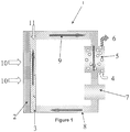
- FIG. 1 there is shown the cathode side of fuel cell 1 in accordance with the invention comprising a polymer electrolyte membrane 2 separating an anode (not shown) from cathode 3,
- Cathode 3 comprises in this diagram reticulated carbon and is therefore porous.
- other cathodic materials such as platinum may be used.
- Polymer electrolyte membrane 2 comprises cation selective National 112 membrane through which protons generated by the (optionally catalytic) oxidation of fuel gas (in this case hydrogen) in the anode chamber pass in operation of the cell. Electrons generated at the anode by the oxidation of fuel gas flow in an electrical circuit (not shown) and are returned to cathode 3.
- Fuel gas in this case hydrogen
- the oxidant in this case air
- Cathode gas reaction chamber 5 the catalyst reoxidation zone
- exhaust 6 through which the by-products of the fuel cell reaction (eg water and heat) can be discharged.
- a catholyte solution comprising the oxidised form of the polyoxometallate redox catalyst is supplied in operation of the cell from catholyte reservoir 7 into the cathode inlet channel 8.
- the catholyte passes into reticulated carbon cathode 3, which is situated adjacent membrane 2.
- the polyoxometallate catalyst is reduced and is then returned to cathode gas reaction chamber 5 via cathode outlet channel 9.
- Catholyte solutions were prepared i) Na 4 H 3 PMo 8 V 4 O 40 ; ii) NaH 6 PMo 8 V 4 O 40 ; iii) KH 6 PMo 8 V 4 O 40 ; iv) Na 0.25 K 0.25 H 6.8 P 1.1 Mo 8 V 4 O 40.4 ; v) K 0.5 H 9.5 P 2 Mo 8 V 4 O 44 , All solutions were made to a concentration of 0.3M.
- catholyte formulations were subjected to a protocol utilising the same test conditions.
- the anode was run flow through with a hydrogen flow rate of 1 L min-1 with the back pressure set to the half-way point between the catholyte in and out pressure.
- Catholyte flow through the cathode was set to a flow rate 150 m! min -1 .
- the catholytes were tested first at 80°C ambient pressure before increasing the pressure applied to regenerator vessel to 3 bar absolute and repeating tests at 80°C with the increased pressure. Tests were then repeated at 100°C and 110°C while continuing to apply 3 bar absolute pressure, before cooling and removing pressure and complete the sequence at 100°C at ambient pressure. Regeneration occurs in the regenerator vessel where air is bubbled into the catholyte through a stainless steel sparge at 3 L min-1.
- I-V curves and constant current operation at 1500 mA cm-2 were recorded for each catholyte at each temperature/pressure combination.
- I-V curves give a good indication of cell performance but however are at a fixed catholyte redox state and so do not take regeneration of the catholyte into account as there is sufficient catholyte volume (650 mL) in the reservoir to complete the polarisation curve in a single pass.
- Constant current operation will also take into account the changing redox state the catholyte and what can be sustained for a given current density, dependant on the rate of regeneration of the catholyte.
- performance improves when pressurising the system i.e. the voltage achieved under load at 80°C, 3 bar absolute is always higher than that achieved with the 80°C ambient data. This is from both increased regeneration capability and from the increased hydrogen pressure required to balance the differential pressures across the cell.
- the voltage achieved at 1500mA cm-2 with Na 4 H 3 PMo 8 V 4 O 40 (the comparative example) is almost the same at 80°C 3 bar absolute as it is at 110°C 3 bar absolute, showing very little temperature dependency.
- the voltage difference achieved when increasing the temperature in this way is significant, with increases between 60-136mV witnessed for the different formulations.
- Figure 2 shows steady-state fuel cell data for a standard catholyte solution, Na 4 H 3 PMo 8 V 4 O 40 , and the effects on performance of increased temperature, pressure, as well as temperature and pressure combined (110°C data omitted because data is unobtainable at that temperature under ambient pressure and there is no noticeable benefit over 100°C with pressure of 2 barG).
- the continuous decline in cell voltage at 100°C / ambient pressure did not abate over time and test was abandoned abruptly.
- the steady-state data shows a significant loss of performance from increasing operating temperature from 80°C to 100°C and beyond due to the solubility oxygen at these temperatures limiting reaction rates.
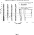
- Fuel cell performance of the standard (comparative) catholyte measured at 80°C and ambient pressure demonstrates superior current densities when compared against catholytes of the present invention, polarisation curve Figure 3 and steady state Figure 6 and Figure 7 .
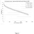
- the standard catholyte does demonstrate an improvement in cell performance with application of elevated temperature and pressure, Figure 4 .
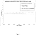
- further comparison between the standard catholyte and those of the present invention at ETP shows a reversal in the order of the best performing system, Figure 5 , Figure 8 and Figure 9 .
- Figure 5 shows how previously poor performing catholytes are now preferred at various current densities (for example see 500 mA/cm2 and 1000 mA/cm2) under ETP.
Landscapes
- Chemical & Material Sciences (AREA)
- Chemical Kinetics & Catalysis (AREA)
- Electrochemistry (AREA)
- General Chemical & Material Sciences (AREA)
- Life Sciences & Earth Sciences (AREA)
- Engineering & Computer Science (AREA)
- Manufacturing & Machinery (AREA)
- Sustainable Development (AREA)
- Sustainable Energy (AREA)
- Inorganic Chemistry (AREA)
- Fuel Cell (AREA)
- Inert Electrodes (AREA)
Description
- The present invention relates to fuel cells for use at elevated temperatures and pressures (ETP), in particular to indirect or redox fuel cells which have applications in microfuel cells for electronic and portable electronic components, and also in larger fuel cells for the automotive industry. The invention also relates to certain catholyte solutions for use in such fuel cells and the use of the cells themselves.
- Fuel cells have been known for portable applications such as automotive and portable electronics technology for very many years, although it is only in recent years that fuel cells have become of serious practical consideration. In its simplest form, a fuel cell is an electrochemical energy conversion device that converts fuel and oxidant into reaction product(s), producing electricity and heat in the process. In one example of such a cell, hydrogen is used as fuel, air or oxygen as an oxidant and the product of the reaction is water. The gases are fed respectively into catalysing, diffusion-type electrodes separated by a solid or liquid electrolyte which carries electrically charged particles between the two electrodes. In an indirect or redox fuel cell, the oxidant (and/or fuel in some cases) is not reacted directly at the electrode but instead reacts with the reduced form (oxidized form for fuel) of a redox couple to oxidise it and this oxidised species is fed to the cathode.
- An acknowledged problem concerning electrochemical fuel cells is that the theoretical potential of a given electrode reaction under defined conditions can be calculated but never completely attained. Imperfections in the system inevitably result in a loss of potential to some level below the theoretical potential attainable from any given reaction. Previous attempts to reduce such imperfections include the selection of catholyte additives which undergo oxidation-reduction reactions in the catholyte solution. For example,
US-A-3294588 discloses the use of quinones and dyes in this capacity. Another redox couple which has been tried is the vanadate/vanadyl couple, as disclosed inUS-A-3279949 . - Several types of proton exchange membrane fuel cells exist. For example, in
US 4396687 a fuel cell is disclosed which comprises regenerable anolyte and catholyte solutions. The anolyte solution is one which is reduced from an oxidised state to a reduced state by exposure of the anolyte solution to hydrogen. According toUS 4396687 , preferred anolyte solutions are tungstosilicic acid (H4SiW12O40) or tungstophosphoric acid (H3PW12O40) in the presence of a catalyst. - The preferred catholyte solution of
US 4396687 is one which is re-oxidised from a reduced state to an oxidized state by direct exposure of the catholyte solution to oxygen. The catholyte ofUS 4396687 includes a mediator component comprising a solution of VOSO4. The mediator functions as an electron sink which is reduced from an oxidation state of V(v) to V(IV). The catholyte also includes a catalyst for regenerating the mediator to its oxidised state, (VO2)2SO4. The catalyst present in the catholyte ofUS 4396687 is a polyoxometailate (POM) solution, namely H5PMo12V2O40. - Besides
US 4396687 , a number of other attempts to use oxometallate catalysts have been made. For example, inUS 5298343 , cathode systems comprising solid metal catalysts, oxometallates and metallic acids, such as molybdic acid are disclosed. - In addition,
WO 96/31912 - The basic structure of the fuel cells used with the present invention is disclosed in
EP1866997 . The fuel cells disclosed herein comprise an anode and a cathode separated by an ion selective polymer electrolyte membrane, the cathode comprising a cathodic material and a proton-conducting polymeric material; means for supplying a fuel to the anode region of the cell; means for supplying an oxidant to the cathode region of the cell; means for providing an electrical circuit between the anode and the cathode; a non-volatile redox couple in solution in flowing fluid communication with the cathode, the redox couple being at least partially reduced at the cathode in operation of the cell, and at least partially re-generated by reaction with the oxidant after such reduction at the cathode. The examples disclose that the catholyte is maintained at 50°C. -
EP1999811 discloses the redox fuel cells as used in the present invention, in combination with a polyoxometallate. This application discloses fuel cells that comprise an anode and a cathode separated by an ion selective polymer electrolyte membrane; means for supplying a fuel to the anode region of the cell; means for supplying an oxidant to the cathode region of the cell; means for providing an electrical circuit between the anode and the cathode; a non-volatile catholyte solution flowing in fluid communication with the cathode, the catholyte solution comprising a polyoxometallate redox couple being at least partially reduced at the cathode in operation of the cell, and at least partially re-generated by reaction with the oxidant after such reduction at the cathode, the catholyte solution comprising at least about 0.075M of the said polyoxometallate. - Zhizhina, E. G.; Simonova, M. V.; Odyakov, V. F.; Matveev, K. I. Applied Catalysis A: General 2007, 319, 91-97 discloses an increase in rate of redox potential of polyoxometallates at increased temperatures (100, 120, 130, 140, 150, 180°C) under a PO2 of 4 atm for chemical synthesis applications. The paper then goes on to state that "increasing temperature, rate and depth of regeneration of any HPA by dioxygen highly grow". However, the same paper also indicates that temperatures above 140°C and preferably above 180°C are beneficial. The aqueous polyoxometallate solutions disclosed herein are complex equilibrium systems containing different anions and cations.
- Odyakov, V. F.; Zhizhina, E. G.; Maksimovskaya, R. I. Applied Catalysis A: General 2008, 342, 126-130 discloses that the regeneration of the polyoxometallate materials above requires "harder conditions" of 150-170°C and PO2 of 2-4 atm, Zhizhina, E. G.; Odyakov, V. F. Applied Catalysis A: General 2009, 358, 254-258 describes a temperature of 150-160°C being required for the re-oxidation of the polyoxometallate catalyst to proceed efficiently. Further, the regeneration conditions for the polyoxometallate catalyst used are a temperature of 170°C and a PO2 of 4 atm.
- Our own
PCT/GB2013/051675 WO2009/040577 describes the use of a CaH4PMo9V3O40 polyoxometallate solution at a temperature of 82°C. - Certain prior art fuel cells all suffer from one or more of the following disadvantages: they are inefficient; they are expensive and/or expensive to assemble; they use expensive and/or environmentally unfriendly materials; they yield inadequate and/or insufficiently maintainable current densities and/or cell potentials; they are too large in their construction; they produce unwanted by-products and/or pollutants and/or noxious materials; and they have not found practical, commercial utility in portable applications such as automotive and portable electronics. With respect to our prior disclosures of POM systems, we seek to improve cell performance and identify new classes of POM systems and optimal operating conditions with respect to them to provide enhanced fuel cell systems.
- It is an object of the present invention to overcome or ameliorate one or more of the aforesaid disadvantages and/or achieve one or more of those goals.
- Accordingly, the present invention provides a redox fuel cell, as defined in the appended claims, comprising an anode and a cathode separated by an ion selective polymer electrolyte membrane; means for supplying a fuel to the anode region of the cell; means for supplying an oxidant to the cathode region of the cell; means for providing an electrical circuit between the anode and the cathode; a non-volatile catholyte solution flowing in fluid communication with the cathode, the catholyte solution comprising a polyoxometallate redox couple being at least partially reduced at the cathode in operation of the cell, and at least partially re-generated by reaction with the oxidant in a regeneration zone after such reduction at the cathode, the catholyte solution further comprising one or more vanadium species that result from the speciation of the polyoxometallate at an elevated temperature and/or pressure, wherein the polyoxometallate is represented by the formula:
Xa[ZbMcOd]
wherein: - X is selected from hydrogen, alkali metals, alkaline earth metals, ammonium, transition metal ions and combinations of two or more thereof;
- Z is selected from B, P, S, As, Si, Ge, Ni, Rh, Sn, Al, Cu, I, Br, F, Fe, Co, Cr, Zn, H2, Te, Mn and Se and combinations of two or more thereof;
- M comprises vanadium and optionally one or more of Mo, W, Nb, Ta, Mn, Fe, Co, Cr, Ni, Zn Rh, Ru, Tl, Al, Ga, In and other metals selected from the 1st, 2nd and 3rd transition metal series and the lanthanide series and combinations of two or more thereof;
- a is a number of X necessary to charge balance the [ZbMcOd] anion;
- b is from 0 to 20;
- c is from 1 to 40;
- d is from 1 to 180; and wherein
- X includes an amount of a non-hydrogen cation and the molar ratio of the non-hydrogen cation to vanadium is more than 0 and less than 1.
- Conventional thinking was that the optimum temperature for operation was 80°C, as performance was thought to decrease at higher temperatures, due to the decrease of oxygen solubility to zero as the boiling point of the catholyte is approached. However, increasing the temperature and pressure causes speciation of the polyoxometallate species, which increases the regeneration rate of the polyoxometallate. By speciation, it is meant that the vanadium species at one point was part of a polyoxometallate structure. This causes improvements in steady state performance as the catholyte is less reduced under the same load. This also increases the redox potential of the polyoxometallate, which results from a dynamic equilibrium between oxidation (occurring via regeneration) and reduction (occurring at the fuel cell electrode).
- Increasing the temperature of the fuel cell is thought to have various advantages, such as reducing the catholyte viscosity, increasing ionic conductivity in the catholyte, increasing ionic conductivity in the membrane and increasing diffusion rates for all species. Increased pressure is thought to increase the maximum concentration of dissolved oxygen, thereby improving oxidation rates.
- It was surprisingly found that the use of polyoxometallate species that contain non-hydrogen cations in low amounts resulted in an improved performance at increased temperatures and pressures. It was previously known that these polyoxometallates had a relatively poor performance in standard fuel cells. However, a dramatic improvement in performance is seen when used in the fuel cells of the present invention. Further, such polyoxometallates were found in many cases to demonstrate a better performance than other known polyoxometallate species in fuel cells of the present invention.
- By low amounts of non-hydrogen cations, it is meant that the molar ratio of the non-hydrogen cation to vanadium is more than 0 and less than 1. Preferably, the molar ratio of the non-hydrogen cation to vanadium is more than 0 and 0.75 or less, even more preferably more than 0 and 0.5 or less, and most preferably more than 0 and 0.25 or less.
- Optionally, there may be more than one type of non-hydrogen cation in the polyoxometallate, i.e. X may comprise more than one type of non-hydrogen cation. In this case, the total molar ratio of all of the non-hydrogen cations to vanadium may be more than 0 and less than 1 and more preferably more than 0 and 0.75 or less, even more preferably more than 0 and 0.5 or less, and most preferably more than 0 and 0.25 or less. Alternatively or as well, the molar ratio of each type of non-hydrogen cation to vanadium may preferably be more than 0 and less than 1 and more preferably more than 0 and 0.75 or less, even more preferably more than 0 and 0.5 or less, and most preferably more than 0 and 0.25 or less.
- Preferred ranges for b are from more than 0 to 10, more preferably from 1 to 5 and most preferably from 1.1 to 5.
- Preferred ranges for c are from 5 to 20, more preferably from 10 to 18, and most preferably 12.
- Preferred ranges for d are from 30 to 70, more preferably 34 to 62, and most preferably 40 to 50.
- The values for a, b, c and d are not necessarily integers.
- Phosphorus is particularly preferred for Z.
- A combination of vanadium and either molybdenum or tungsten is particularly preferred for M. The molar ratio of molybdenum or tungsten to vanadium is preferably 2:1.
- Preferably, the polyoxometallate contains from 2 to 10 vanadium centres.
- A combination of hydrogen and an alkali metal and/or alkaline earth metal is particularly preferred for X. One such preferred combination is hydrogen and sodium.
- Specific examples of polyoxometallates for use in the present invention include KH6PV4Mo8O40, NaH6PV4Mo8O40 and K0.5H9.5P2V4Mo8O44. Preferably, the speciation of the polyoxometaliate occurs in situ.
- The elevated temperature is above 80°C and even more preferably above 90°C, 100°C or 110°C, However, certain membranes used in the fuel cell of the present invention may become damaged at above 120°C. The elevated pressure is above ambient pressure. More preferably, the elevated pressure is above 0.5 barG, above 0.75 barG, above 1 barG, above 1.25barG or above 1.5 barG. Elevated pressures of from about 1.5barG to about 2.5barG, for example from around 1,75barG to about 2.25barG, for example around 2 barG pressure are preferred. The elevated pressure is also preferably below 2.5 barG pressure. BarG pressure means guage pressure and is defined as the pressure above ambient (atmospheric) pressure. In the invention both elevated temperature and pressure are used. This provides further benefits as the increase in pressure allows for a greater increase in temperature than would otherwise be possible, as the catholyte temperature is limited by its boiling point. The elevated temperature is therefore preferably below the boiling point for the catholyte solution.
- The elevated temperature is preferably in the regeneration zone and/or in the cathode/anode region of the cell. More preferably, the elevated temperature is in the regeneration zone. Further, the elevated pressure is preferably in the regeneration zone and/or in the cathode/anode region of the ceil. More preferably, the elevated pressure is in the regeneration zone.
- The cell is maintained in operation thereof (in the regeneration zone and/or the cathode/anode region as mentioned above) at elevated temperature and pressure, as defined hereinabove.
- The concentration of the polyoxometallate in the catholyte solution is preferably at least about 0.075M or 0.08M, more preferably at least about 0.1M, still more preferably at least about 0.125M and most preferably at least about 0.15M,
- In one preferred embodiment of the invention, the ion selective PEM is a cation selective membrane which is selective in favour of protons versus other cations,
- The cation selective polymer electrolyte membrane may be formed from any suitable material, but preferably comprises a polymeric substrate having cation exchange capability. Suitable examples include fluororesin-type ion exchange resins and non-fluororesin-type ion exchange resins. Fluororesin-type ion exchange resins include perfluorocarboxylic acid resins, perfluorosulfonic acid resins and the like. Perfluorosulfonic acid resins are preferred, for example "Nafion" (Du Pont Inc.), "Flemion" (Asahi Gas Ltd), "Aciplex" (Asahi Kasei Inc) and the like. Non-fluororesin-type ion exchange resins include polyvinyl alcohols, polyalkylene oxides, styrene-divinylbenzene ion exchange resins and the like, and metal salts thereof. Preferred non-fluororesin-type ion exchange resins include polyalkylene oxide-alkali metal salt complexes. These are obtainable by polymerizing an ethylene oxide oligomer in the presence of lithium chlorate or another alkali metal salt, for example. Other examples include phenolsulphonic acid, polystyrene sulphonic, polytriflurostyrene sulphonic, sulphonated trifluorostyrene, sulphonated copolymers based on α,β,β triflurostyrene monomer and radiation-grafted membranes. Non-fluorinated membranes include sulphonated poly(phenylquinoxalines), poly (2,6 diphenyl-4-phenylene oxide), poly(arylether sulphone), poly(2,6-diphenylenol), acid-doped polybenzimidazole, sulphonated polyimides, styrene/ethyiene-butadiene/styrene triblock copolymers, partially sulphonated polyarylene ether sulphone, partially sulphonated polyether ether ketone (PEEK) and polybenzyl suphonic acid siloxane (PBSS).
- The proton exchange membrane fuel cell of the present invention may work in the following way:
- a) H+ ions are formed at an anode situated adjacent to a proton exchange membrane;
- b) the catholyte with its redox couple in an oxidised state is supplied to a cathode situated oppositely adjacent to the proton exchange membrane;
- c) the catholyte is allowed to become reduced upon contact with the cathode concomitantly with H+ ions passing through the membrane to balance charge;
- d) the catholyte may be passed from the cathode to a reoxidation zone wherein the catholyte is reoxidised; and
- e) the catholyte may then be passed from the reoxidation zone to the catholyte reservoir.
- In a preferred embodiment, the catholyte is supplied from a catholyte reservoir.
- The cell may be cyclic and the catholyte can be repeatedly oxidised and reduced without having to be replaced.
- The fuel cell of the invention may comprise a reformer configured to convert available fuel precursor such as LPG, LNG, gasoline or low molecular weight alcohols into a fuel gas (eg hydrogen) through a steam reforming reaction. The cell may then comprise a fuel gas supply device configured to supply the reformed fuel gas to the anode chamber
- It may be desirable in certain applications of the cell to provide a fuel humidifier configured to humidify the fuel, eg hydrogen. The cell may then comprise a fuel supply device configured to supply the humidified fuel to the anode chamber.
- An electricity loading device configured to allow the fuel cell to provide electric power may also be provided in association with the fuel cell of the invention.
- Preferred fuels include hydrogen; low molecular weight alcohols, aldehydes and carboxylic acids; sugars and biofuels as well as LPGLNG or gasoline.
- Preferred oxidants include air, oxygen and peroxides
- The anode in the redox fuel cell of the invention may for example be a hydrogen gas anode or a direct methanol anode; other low molecular weight alcohols such as ethanol, propanol, dipropylene glycol; ethylene glycol; aldehydes formed from these; and acid species such as formic acid, ethanoic acid etc. In addition, the anode may be formed from a bio-fuel cell type system where a bacterial species consumes a fuel and either produces a mediator which is oxidized at the electrode, or the bacteria themselves are adsorbed at the electrode and directly donate electrons to the anode.
- The cathode in the redox fuel cell of the invention may comprise as cathodic material carbon, gold, platinum, nickel or a metal oxide species. However, it is preferable that expensive cathodic materials are avoided and therefore preferred cathodic materials include carbon, nickel and metal oxide. One preferable material for the cathodes is reticulated vitreous carbon or carbon fibre based electrodes such as carbon felt. Another is nickel foam. The cathodic material may be constructed from a fine dispersion of particulate cathodic material, the particulate dispersion being held together by a suitable adhesive, or by a proton conducting polymeric material. The cathode is designed to create maximum flow of catholyte solution to the cathode surface. Thus it may consist of shaped flow regulators or a three dimensional electrode; the liquid flow may be managed in a flow-by arrangement where there is a liquid channel adjacent to the electrode, or in the case of the three dimensional electrode, where the liquid is forced to flow through the electrode. It is intended that the surface of the electrode is also the electrocatalyst, but it may be beneficial to adhere the electrocatalyst in the form of deposited particles on the surface of the electrode.
- The redox couple flowing in solution in the cathode chamber in operation of the cell is used in the invention as a catalyst for the reduction of oxygen in the regeneration chamber, in accordance with the following (wherein Sp is the redox couple species).
O2 + 4Spred + 4H+ → 2H2O + 4Spox
- The palyoxometaiiate redox couple, as well as any other ancillary redox couple, utilised in the fuel cell of the invention should be non-volatile and is preferably soluble in aqueous solvent. Preferred redox couples should react with the oxidant at a rate effective to generate a useful current in the electrical circuit of the fuel cell and react with the oxidant such that water is the ultimate end product of the reaction.
- The fuel cell of the invention preferably requires the presence of at least about 0.075M of a polyoxometallate species in the catholyte solution. However, in some circumstances it may also be possible to include other redox couples in the catholyte solution in addition to the polyoxometallate species. There are many suitable examples of such ancillary redox couples, including ligated transition metal complexes and other polyoxometallate species. Specific examples of suitable transition metals ions which can form such complexes include manganese in oxidation states II - V, iron I-IV, copper I-III, cobalt I-III, nickel I-III, chromium (II-VII), titanium II-IV, tungsten IV-VI, vanadium II - V and molybdenum II-VI. Ligands can contain carbon, hydrogen, oxygen, nitrogen, sulphur, halides and/or phosphorus, Ligands may be chelating complexes such as Fe/EDTA and Mn/EDTA, NTA and 2-hydroxyethylenediaminetriacetic acid, or non-chelating such as cyanide. The catholyte solution of the present invention may also be substantially free from any ancilliary redox species other than the vanadium species..
- The fuel cell of the invention may operate straightforwardly with a redox couple catalysing in operation of the fuel cell the reduction of oxidant in the cathode chamber. However, in some cases, and with some redox couples, it may be necessary and/or desirable to incorporate a catalytic mediator in the cathode chamber.
- Also provided is a catholyte solution for use in a redox fuel ceil as outlined above.
- Another aspect of the present invention provides the use of a redox fuel cell, as outlined above, wherein during operation, all or part of the fuel cell is maintained at an elevated temperature and/or pressure. The elevated temperature is above 80°C and is more preferably above 90°C, 100°C or 110°C. However, the elevated temperature is preferably no more than 120°C. The elevated pressure is above ambient pressure, and more preferably above 0.5 barG, above 0.75 barG, above 1 barG, above 1,25barG or above 1.5 barG. Elevated pressures of from about 1.5barG to about 2.5barG, for example from around 1.75barG to about 2.25barG, for example around 2 barG pressure are preferred. The elevated pressure is also preferably below 2.5 barG. Both an elevated temperature and pressure (as defined herein) is used.
- The elevated temperature may be in the regeneration zone and/or in the cathode/anode region of the cell. Preferably, the elevated temperature is in the regeneration zone. Further, the elevated pressure may be in the regeneration zone and/or in the cathode/anode region of the cell. Preferably, the elevated pressure is in the regeneration zone.
- Also provided is a use of a polyoxometa!late in a fuel cell operating at elevated temperatures and/or pressures, wherein the poiyoxometallate is as defined above.
- Various aspects of the present invention will now be more particularly described with reference to the following Figures which illustrate an embodiment of the present invention and Examples demonstrating it:
-
Figure 1 illustrates a schematic view of the cathode compartment of a fuel cell in accordance with the present invention; -
Figure 2 shows the steady-state fuel cell performance of standard (comparative) POM Na4H3PV4Mo8O40 with variability in operating temperature, pressure, as well as temperature and pressure; -
Figure 3 shows polarisation curves of example catholytes (in accordance with the invention) at 500 mAlcm2; 80°C; ambient pressure. The standard (comparative) catholyte (Na4H3PV4Mo8O40) shows preferred performance under such standard operating conditions. -
Figure 4 shows polarisation curves of the standard (comparative) catholyte Na4H3PV4Mo8O40 [0.30M], demonstrating a modest and unsurprising improvement in cell performance as a result of an increase in operating temperature and pressure. -
Figure 5 shows polarisation curves of example catholyte solutions (in accordance with the invention) at 500 mA/s, 110°C, 2 barG pressure. Performance appears to siginificantly favour catholytes of the present invention under conditions described as elevated temperature and pressure. The performance reversal with respect to the comparative catholyte is surprising for the catholytes of the present invention. -
Figure 6 shows steady-state fuel cell performance of various catholytes in accordance with the invention vs a standard (comparative) catholyte at 1500 mA/cm2, 80°C, ambient pressure. Performance of the standard (comparative) catholyte exceeds those of the present invention under these standard conditions. -
Figure 7 shows a close up view of part of the data fromFigure 6 , showing steady state fuel cell performance of catholytes at 1500 mA/cm2, 80°C, ambient pressure. Performance of the standard (comparative) catholyte exceeds those of the present invention under these standard conditions. -
Figure 8 shows steady-state fuel cell performance of various catholytes in accordance with the invention vs a standard (comparative) catholyte at 1500 mA/cm2, 110°C, 2 barG pressure. Performance improvements of the standard (comparative) catholyte are minimal compared to the type of catholytes investigated in the present invention. -
Figure 9 shows a close up view of part of the date fromFigure 8 , showing steady state fuel cell performance of catholytes at 1500 mA/cm2, 110°C, 2 barG. Performance improvements of the catholytes of the present invention are capable of demonstrating superior steady-state performance in addition to the improvement in polarisation curves,Figure 4 , compared to standard catholytes of the prior art, with the application of elevated temperature and pressure. - Referring to
Figure 1 , there is shown the cathode side of fuel cell 1 in accordance with the invention comprising apolymer electrolyte membrane 2 separating an anode (not shown) fromcathode 3,Cathode 3 comprises in this diagram reticulated carbon and is therefore porous. However, other cathodic materials such as platinum may be used.Polymer electrolyte membrane 2 comprises cation selective Nation 112 membrane through which protons generated by the (optionally catalytic) oxidation of fuel gas (in this case hydrogen) in the anode chamber pass in operation of the cell. Electrons generated at the anode by the oxidation of fuel gas flow in an electrical circuit (not shown) and are returned tocathode 3. Fuel gas (in this case hydrogen) is supplied to the fuel gas passage of the anode chamber (not shown), while the oxidant (in this case air) is supplied to oxidant inlet 4 of cathodegas reaction chamber 5. Cathode gas reaction chamber 5 (the catalyst reoxidation zone) is provided with exhaust 6, through which the by-products of the fuel cell reaction (eg water and heat) can be discharged. - A catholyte solution comprising the oxidised form of the polyoxometallate redox catalyst is supplied in operation of the cell from
catholyte reservoir 7 into thecathode inlet channel 8. The catholyte passes intoreticulated carbon cathode 3, which is situatedadjacent membrane 2. As the catholyte passes throughcathode 3, the polyoxometallate catalyst is reduced and is then returned to cathodegas reaction chamber 5 viacathode outlet channel 9. - Due to the advantageous composition of the catholyte of the present invention, reoxidation of the catalyst occurs very rapidly, which allows the fuel cell to produce a higher sustainable current than with catholytes of the prior art.
- Catholyte solutions were prepared i) Na4H3PMo8V4O40; ii) NaH6PMo8V4O40; iii) KH6PMo8V4O40; iv) Na0.25K0.25H6.8P1.1Mo8V4O40.4; v) K0.5H9.5P2Mo8V4O44, All solutions were made to a concentration of 0.3M.
- Under conditions of elevated temperature and/or pressure i) Na4H3PMo8V4O40 is comparative and the other catholyte solutions are all in accordance with the invention.
- Each formulation was tested with a new 25cm2 active area single cell containing a carbon felt electrode at the cathode, a commercially available reinforced 25 µm thick PFSA membrane which is only catalyst coated on the anode side and a gas diffusion layer with a microporous layer at the anode, nominally 300 µm thick. All cells were subjected to leak and short circuit tests prior to commencement of testing.
- All catholyte formulations were subjected to a protocol utilising the same test conditions. The anode was run flow through with a hydrogen flow rate of 1 L min-1 with the back pressure set to the half-way point between the catholyte in and out pressure. Catholyte flow through the cathode was set to a flow rate 150 m! min-1. The catholytes were tested first at 80°C ambient pressure before increasing the pressure applied to regenerator vessel to 3 bar absolute and repeating tests at 80°C with the increased pressure. Tests were then repeated at 100°C and 110°C while continuing to apply 3 bar absolute pressure, before cooling and removing pressure and complete the sequence at 100°C at ambient pressure. Regeneration occurs in the regenerator vessel where air is bubbled into the catholyte through a stainless steel sparge at 3 L min-1.
- I-V curves and constant current operation at 1500 mA cm-2 were recorded for each catholyte at each temperature/pressure combination. I-V curves give a good indication of cell performance but however are at a fixed catholyte redox state and so do not take regeneration of the catholyte into account as there is sufficient catholyte volume (650 mL) in the reservoir to complete the polarisation curve in a single pass. Constant current operation will also take into account the changing redox state the catholyte and what can be sustained for a given current density, dependant on the rate of regeneration of the catholyte.
- In all examples, performance improves when pressurising the system i.e. the voltage achieved under load at 80°C, 3 bar absolute is always higher than that achieved with the 80°C ambient data. This is from both increased regeneration capability and from the increased hydrogen pressure required to balance the differential pressures across the cell. Where the catholytes behave differently is on addition of temperature, the voltage achieved at 1500mA cm-2 with Na4H3PMo8V4O40 (the comparative example) is almost the same at 80°
C 3 bar absolute as it is at 110°C 3 bar absolute, showing very little temperature dependency. However for all other solutions the voltage difference achieved when increasing the temperature in this way is significant, with increases between 60-136mV witnessed for the different formulations. -
Figure 2 shows steady-state fuel cell data for a standard catholyte solution, Na4H3PMo8V4O40, and the effects on performance of increased temperature, pressure, as well as temperature and pressure combined (110°C data omitted because data is unobtainable at that temperature under ambient pressure and there is no noticeable benefit over 100°C with pressure of 2 barG). The continuous decline in cell voltage at 100°C / ambient pressure did not abate over time and test was abandoned abruptly. The steady-state data shows a significant loss of performance from increasing operating temperature from 80°C to 100°C and beyond due to the solubility oxygen at these temperatures limiting reaction rates. The detrimental effect of increasing temperature can be overcome by application of increased pressure; however, the best performing catholyte under standard conditions (i.e not at elevated temperature and pressure; but at 80°C and ambient pressure) shows an almost negligible improvement in performance (+33 mV at 110°C; 2 barG) as a result of the application of ETP,Figure 2 and Table 1, - Fuel cell performance of the standard (comparative) catholyte measured at 80°C and ambient pressure demonstrates superior current densities when compared against catholytes of the present invention, polarisation curve
Figure 3 and steady stateFigure 6 andFigure 7 . The standard catholyte does demonstrate an improvement in cell performance with application of elevated temperature and pressure,Figure 4 . However, further comparison between the standard catholyte and those of the present invention at ETP shows a reversal in the order of the best performing system,Figure 5 ,Figure 8 andFigure 9 .Figure 5 shows how previously poor performing catholytes are now preferred at various current densities (for example see 500 mA/cm2 and 1000 mA/cm2) under ETP. This behaviour is further exemplified in steady-state fuel cell performance with catholytes of the present invention showing a more significant improvement in performance to standard catholyte solution which are a direct result of speciation effects of the catholytes of the present invention when utilised in a fuel cell with elevated temperature and pressure, data supplied in brackets Table 1.Table 1: Steady state cell voltage achieved under various operating conditions with catholytes of the present invention compared against the standard performing catholyte. Catholyte Formulation Temp (°C) Pressure (barG) Steady-State Cell Voltage (V) - with ETP performance improvement in brackets Na4H3PV4Mo8O40 80 0 0.377 Na4H3PV4Mo8O40 100 0 0.202 Na4H3PV4Mo8O40 80 2 0.417 Na4H3PV4Mo8O40 100 2 0.417 Na4H3PV4Mo8O40 110 2 0.410 (+0.033V) NaH8PV4Mo8O40 80 0 0.293 NaH6PV4Mo8O40 110 2 0.399 (+0.106 V) KH6PV4Mo8O40 80 0 0.277 KH6PV4Mo8O40 110 2 0.458 (+0.181 V) Na0.25K0.25H6.8P1.1V4Mo8O40.4 80 0 0.158 Na0.25K0.25H6.8P1.1V4Mo8O40.4 110 2 0.419 (+0.261 V) K0.5H9.5P2V4Mo8O44 80 0 0.180 K0.5H9.5P2V4Mo8O44 110 2 0.412 (+0,232 V) - These data demonstrate that whilst increasing the temperature and pressure of operation produces a marginal improvement in a standard prior art POM catholyte, the magnitude of that improvement is very much formulation dependant, and is much greater and surprisingly so for the catholyte systems under the conditions as stipulated in the present invention which include vanadium and an amount of a non-hydrogen cation, and wherein the molar ratio of the non-hydrogen cation to vanadium is more than 0 and less than 1.
Claims (15)
- A redox fuel cell comprising an anode and a cathode separated by an ion selective polymer electrolyte membrane; means for supplying a fuel to the anode region of the cell; means for supplying an oxidant to the cathode region of the cell; means for providing an electrical circuit between the anode and the cathode; a non-volatile catholyte solution flowing in fluid communication with the cathode, the catholyte solution comprising a polyoxometallate redox couple being at least partially reduced at the cathode in operation of the cell, and at least partially re-generated by reaction with the oxidant in a regeneration zone after such reduction at the cathode, the catholyte solution further comprising one or more vanadium species that result from the speciation of the polyoxometallate at a temperature above 80°C and a pressure above ambient pressure, wherein the polyoxometallate is represented by the formula:
Xa[ZbMcOd]
wherein:X is selected from hydrogen, alkali metals, alkaline earth metals, ammonium, transition metal ions and combinations of two or more thereof;Z is selected from B, P, S, As, Si, Ge, Ni, Rh, Sn, Al, Cu, I, Br, F, Fe, Co, Cr, Zn, H2, Te, Mn and Se and combinations of two or more thereof;M comprises vanadium and optionally one or more of Mo, W, Nb, Ta, Mn, Fe, Co, Cr, Ni, Zn Rh, Ru, Tl, Al, Ga, In and other metals selected from the 1st, 2nd and 3rd transition metal series and the lanthanide series and combinations of two or more thereof;a is a number of X necessary to charge balance the [ZbMcOd] anion;b is from 0 to 20;c is from 1 to 40;d is from 1 to 180; and whereinX includes an amount of a non-hydrogen cation and the molar ratio of the non-hydrogen cation to vanadium is more than 0 and less than 1. - The redox fuel cell according to Claim 1 wherein the molar ratio of the non-hydrogen cation to vanadium is less than 0.75, less than 0.5 or 0.25 or less, and/or optionally
wherein:b is from 1 to 5;c is from 5 to 20;d is from 30 to 70; and/orZ consists of phosphorus. - The redox fuel cell according to Claim 1 or 2 wherein M consists of vanadium and either molybdenum or tungsten, and optionallywherein the molar ratio of molybdenum or tungsten to vanadium is 2:1, and/or optionallycontaining from 2 to 10 vanadium centres in the polyoxometallate, and/or optionallywherein X comprises a combination of hydrogen and alkali metal and/or alkaline earth metal ions.
- The redox fuel cell according to any preceding claim wherein X comprises more than one type of non-hydrogen cation, and optionallywherein the total molar ratio of all of the non-hydrogen cations to vanadium is more than 0 and less than 1, or optionallywherein the molar ratio of each of the non-hydrogen cations to vanadium is more than 0 and less than 1.
- The redox fuel cell according to any preceding claim wherein the polyoxometallate isKH6PV4Mo8O40;NaH6PV4Mo8O40;K0.5H9.5P2V4Mo8O44; orNa0.25K0.25H6.8P1.1V4Mo8O40.4
- The redox fuel cell according to any preceding claim wherein the speciation of the polyoxometallate occurs in situ, and/or optionallywherein the temperature is above 90°C, 100°C or 110°C, and/or optionallywherein the temperature is no more than 120°C, and/or optionally wherein the temperature is below the boiling point for the catholyte solution, and/or optionallywherein the cell is maintained in operation at the temperature in the regeneration zone and/or in the cathode/anode region of the cell, preferably in the regeneration zone.
- The redox fuel cell according to any preceding claim wherein the pressure is above 0.5 barG, above 0.75 barG, above 1 barG, above 1.25 barG or above 1.5 barG, or from 1.5 barG to 2.5 barG or from 1.75 barG to 2.25 barG, or around 2 barG, and/or
optionally
wherein the cell is maintained in operation at the pressure in the regeneration zone and/or in the cathode/anode region of the cell, preferably in the regeneration zone. - The redox fuel cell according to any preceding claim wherein the catholyte solution comprises at least one ancillary redox species, and optionally,wherein the ancillary redox species is selected from ligated transition metal complexes, further polyoxometallate species, and combinations thereof, and optionallywherein the transition metal(s) in the transition metal complexes are selected from manganese in oxidation states II - V, iron I-IV, copper I-III, cobalt I-III, nickel I-III, chromium (II-VII), titanium II-IV, tungsten IV-VI, vanadium II - V and molybdenum II-VI.
- The redox fuel cell according to any one of Claims 1 to 7 wherein the catholyte solution is substantially free from any ancillary redox species, other than the vanadium species.
- A catholyte solution for use in a redox fuel cell according to any one of Claims 1 to 9.
- Use of a fuel cell according to any one of Claims 1 to 9 wherein all or part of the fuel cell is maintained during operation at a temperature above 80°C and a pressure above ambient pressure.
- Use according to Claim 11 wherein the temperature is above 90°C or above 100°C or above 110°C, and/or optionallywherein the temperature is no more than 120°C, and/or optionallywherein the temperature is maintained in the regeneration zone and/or in the cathode/anode region of the cell, preferably in the regeneration zone.
- The use according to Claim 11 or 12 wherein the pressure is above 0.5 barG, above 0.75 barG, above 1 barG, above 1.25 barG or above 1.5 barG, or from 1.5 barG to 2.5 barG or from 1.75 barG to 2 25 barG, or 2 barG, and/or optionally wherein the pressure is maintained in the regeneration zone and/or in the cathode/anode region of the cell, preferably in the regeneration zone.
- Use of a polyoxometallate in a fuel cell operating at elevated temperatures and/or pressures, wherein the polyoxometallate is as defined in any one of Claims 1 to 5.
- An automotive system, electronic device or combined heat and power (chp) system incorporating the fuel cell of any one of claims 1 to 9.
Applications Claiming Priority (2)
| Application Number | Priority Date | Filing Date | Title |
|---|---|---|---|
| GB1311295.8A GB2515511A (en) | 2013-06-25 | 2013-06-25 | Polyoxometallates for use at elevated temperatures and pressures |
| PCT/GB2014/051945 WO2014207465A1 (en) | 2013-06-25 | 2014-06-25 | Polyoxometallates for use at elevated temperatures and pressures |
Publications (2)
| Publication Number | Publication Date |
|---|---|
| EP3014688A1 EP3014688A1 (en) | 2016-05-04 |
| EP3014688B1 true EP3014688B1 (en) | 2019-02-27 |
Family
ID=48998934
Family Applications (1)
| Application Number | Title | Priority Date | Filing Date |
|---|---|---|---|
| EP14735653.9A Not-in-force EP3014688B1 (en) | 2013-06-25 | 2014-06-25 | Polyoxometallates for use at elevated temperatures and pressures |
Country Status (4)
| Country | Link |
|---|---|
| US (1) | US10468703B2 (en) |
| EP (1) | EP3014688B1 (en) |
| GB (1) | GB2515511A (en) |
| WO (1) | WO2014207465A1 (en) |
Families Citing this family (1)
| Publication number | Priority date | Publication date | Assignee | Title |
|---|---|---|---|---|
| GB2549708B (en) * | 2016-04-21 | 2019-01-02 | Siemens Ag | A reduction-oxidation flow battery |
Family Cites Families (8)
| Publication number | Priority date | Publication date | Assignee | Title |
|---|---|---|---|---|
| US20060024539A1 (en) * | 2004-07-29 | 2006-02-02 | Dumesic James A | Catalytic method to remove CO and utilize its energy content in CO-containing streams |
| IN266777B (en) * | 2006-03-24 | 2015-06-01 | Acal Energy Ltd | |
| GB0608079D0 (en) * | 2006-04-25 | 2006-05-31 | Acal Energy Ltd | Fuel cells |
| GB0718349D0 (en) * | 2007-09-20 | 2007-10-31 | Acal Energy Ltd | Fuel cells |
| GB0718577D0 (en) * | 2007-09-24 | 2007-10-31 | Acal Energy Ltd | Fuel cells |
| BR112012020301A2 (en) * | 2010-03-02 | 2016-04-26 | Acal Energy Ltd | device for generating fine bubbles, method for manufacturing a device for generating fine bubbles, method for generating fine bubbles, catholyte regeneration system, and use of the device |
| US8574534B2 (en) * | 2010-03-18 | 2013-11-05 | Ut-Battelle, Llc | Carbon films produced from ionic liquid carbon precursors |
| US8137831B1 (en) * | 2011-06-27 | 2012-03-20 | Primus Power Corporation | Electrolyte flow configuration for a metal-halogen flow battery |
-
2013
- 2013-06-25 GB GB1311295.8A patent/GB2515511A/en not_active Withdrawn
-
2014
- 2014-06-25 EP EP14735653.9A patent/EP3014688B1/en not_active Not-in-force
- 2014-06-25 US US14/900,537 patent/US10468703B2/en active Active
- 2014-06-25 WO PCT/GB2014/051945 patent/WO2014207465A1/en not_active Ceased
Non-Patent Citations (1)
| Title |
|---|
| None * |
Also Published As
| Publication number | Publication date |
|---|---|
| US10468703B2 (en) | 2019-11-05 |
| WO2014207465A1 (en) | 2014-12-31 |
| GB2515511A (en) | 2014-12-31 |
| GB201311295D0 (en) | 2013-08-14 |
| US20160156059A1 (en) | 2016-06-02 |
| EP3014688A1 (en) | 2016-05-04 |
Similar Documents
| Publication | Publication Date | Title |
|---|---|---|
| US9005828B2 (en) | Redox fuel cells with a catholyte solution containing a polyoxometallate | |
| EP2193568B1 (en) | Redox fuel cell | |
| JP5913364B2 (en) | Renewable fuel cell with catholyte containing polyoxometalate and vanadium (IV) compound | |
| JP7040805B2 (en) | Redox fuel cell and its use | |
| JP2018081918A (en) | Indirect redox fuel cell including tungsten polyoxometalate containing catholyte | |
| US10468703B2 (en) | Polyozometallates for use at elevated temperatures and pressures |
Legal Events
| Date | Code | Title | Description |
|---|---|---|---|
| PUAI | Public reference made under article 153(3) epc to a published international application that has entered the european phase |
Free format text: ORIGINAL CODE: 0009012 |
|
| 17P | Request for examination filed |
Effective date: 20160106 |
|
| AK | Designated contracting states |
Kind code of ref document: A1 Designated state(s): AL AT BE BG CH CY CZ DE DK EE ES FI FR GB GR HR HU IE IS IT LI LT LU LV MC MK MT NL NO PL PT RO RS SE SI SK SM TR |
|
| AX | Request for extension of the european patent |
Extension state: BA ME |
|
| DAX | Request for extension of the european patent (deleted) | ||
| 19U | Interruption of proceedings before grant |
Effective date: 20170308 |
|
| 19W | Proceedings resumed before grant after interruption of proceedings |
Effective date: 20180601 |
|
| RAP1 | Party data changed (applicant data changed or rights of an application transferred) |
Owner name: UNIVERSITY OF CHESTER |
|
| RIC1 | Information provided on ipc code assigned before grant |
Ipc: H01M 8/04186 20160101ALI20180719BHEP Ipc: H01M 8/1018 20160101ALN20180719BHEP Ipc: H01M 8/18 20060101AFI20180719BHEP |
|
| GRAP | Despatch of communication of intention to grant a patent |
Free format text: ORIGINAL CODE: EPIDOSNIGR1 |
|
| STAA | Information on the status of an ep patent application or granted ep patent |
Free format text: STATUS: GRANT OF PATENT IS INTENDED |
|
| INTG | Intention to grant announced |
Effective date: 20180917 |
|
| RIN1 | Information on inventor provided before grant (corrected) |
Inventor name: ROCHESTER, DAVID LEE Inventor name: CREETH, ANDREW Inventor name: HERBERT, MATTHEW ALEXANDER |
|
| GRAS | Grant fee paid |
Free format text: ORIGINAL CODE: EPIDOSNIGR3 |
|
| GRAA | (expected) grant |
Free format text: ORIGINAL CODE: 0009210 |
|
| STAA | Information on the status of an ep patent application or granted ep patent |
Free format text: STATUS: THE PATENT HAS BEEN GRANTED |
|
| AK | Designated contracting states |
Kind code of ref document: B1 Designated state(s): AL AT BE BG CH CY CZ DE DK EE ES FI FR GB GR HR HU IE IS IT LI LT LU LV MC MK MT NL NO PL PT RO RS SE SI SK SM TR |
|
| REG | Reference to a national code |
Ref country code: GB Ref legal event code: FG4D |
|
| REG | Reference to a national code |
Ref country code: CH Ref legal event code: EP |
|
| REG | Reference to a national code |
Ref country code: AT Ref legal event code: REF Ref document number: 1102662 Country of ref document: AT Kind code of ref document: T Effective date: 20190315 |
|
| REG | Reference to a national code |
Ref country code: IE Ref legal event code: FG4D |
|
| REG | Reference to a national code |
Ref country code: DE Ref legal event code: R096 Ref document number: 602014041810 Country of ref document: DE |
|
| REG | Reference to a national code |
Ref country code: NL Ref legal event code: MP Effective date: 20190227 |
|
| REG | Reference to a national code |
Ref country code: LT Ref legal event code: MG4D |
|
| PG25 | Lapsed in a contracting state [announced via postgrant information from national office to epo] |
Ref country code: NO Free format text: LAPSE BECAUSE OF FAILURE TO SUBMIT A TRANSLATION OF THE DESCRIPTION OR TO PAY THE FEE WITHIN THE PRESCRIBED TIME-LIMIT Effective date: 20190527 Ref country code: FI Free format text: LAPSE BECAUSE OF FAILURE TO SUBMIT A TRANSLATION OF THE DESCRIPTION OR TO PAY THE FEE WITHIN THE PRESCRIBED TIME-LIMIT Effective date: 20190227 Ref country code: LT Free format text: LAPSE BECAUSE OF FAILURE TO SUBMIT A TRANSLATION OF THE DESCRIPTION OR TO PAY THE FEE WITHIN THE PRESCRIBED TIME-LIMIT Effective date: 20190227 Ref country code: SE Free format text: LAPSE BECAUSE OF FAILURE TO SUBMIT A TRANSLATION OF THE DESCRIPTION OR TO PAY THE FEE WITHIN THE PRESCRIBED TIME-LIMIT Effective date: 20190227 Ref country code: PT Free format text: LAPSE BECAUSE OF FAILURE TO SUBMIT A TRANSLATION OF THE DESCRIPTION OR TO PAY THE FEE WITHIN THE PRESCRIBED TIME-LIMIT Effective date: 20190627 Ref country code: NL Free format text: LAPSE BECAUSE OF FAILURE TO SUBMIT A TRANSLATION OF THE DESCRIPTION OR TO PAY THE FEE WITHIN THE PRESCRIBED TIME-LIMIT Effective date: 20190227 |
|
| PG25 | Lapsed in a contracting state [announced via postgrant information from national office to epo] |
Ref country code: RS Free format text: LAPSE BECAUSE OF FAILURE TO SUBMIT A TRANSLATION OF THE DESCRIPTION OR TO PAY THE FEE WITHIN THE PRESCRIBED TIME-LIMIT Effective date: 20190227 Ref country code: BG Free format text: LAPSE BECAUSE OF FAILURE TO SUBMIT A TRANSLATION OF THE DESCRIPTION OR TO PAY THE FEE WITHIN THE PRESCRIBED TIME-LIMIT Effective date: 20190527 Ref country code: HR Free format text: LAPSE BECAUSE OF FAILURE TO SUBMIT A TRANSLATION OF THE DESCRIPTION OR TO PAY THE FEE WITHIN THE PRESCRIBED TIME-LIMIT Effective date: 20190227 Ref country code: GR Free format text: LAPSE BECAUSE OF FAILURE TO SUBMIT A TRANSLATION OF THE DESCRIPTION OR TO PAY THE FEE WITHIN THE PRESCRIBED TIME-LIMIT Effective date: 20190528 Ref country code: IS Free format text: LAPSE BECAUSE OF FAILURE TO SUBMIT A TRANSLATION OF THE DESCRIPTION OR TO PAY THE FEE WITHIN THE PRESCRIBED TIME-LIMIT Effective date: 20190627 Ref country code: LV Free format text: LAPSE BECAUSE OF FAILURE TO SUBMIT A TRANSLATION OF THE DESCRIPTION OR TO PAY THE FEE WITHIN THE PRESCRIBED TIME-LIMIT Effective date: 20190227 |
|
| REG | Reference to a national code |
Ref country code: AT Ref legal event code: MK05 Ref document number: 1102662 Country of ref document: AT Kind code of ref document: T Effective date: 20190227 |
|
| PG25 | Lapsed in a contracting state [announced via postgrant information from national office to epo] |
Ref country code: AL Free format text: LAPSE BECAUSE OF FAILURE TO SUBMIT A TRANSLATION OF THE DESCRIPTION OR TO PAY THE FEE WITHIN THE PRESCRIBED TIME-LIMIT Effective date: 20190227 Ref country code: EE Free format text: LAPSE BECAUSE OF FAILURE TO SUBMIT A TRANSLATION OF THE DESCRIPTION OR TO PAY THE FEE WITHIN THE PRESCRIBED TIME-LIMIT Effective date: 20190227 Ref country code: DK Free format text: LAPSE BECAUSE OF FAILURE TO SUBMIT A TRANSLATION OF THE DESCRIPTION OR TO PAY THE FEE WITHIN THE PRESCRIBED TIME-LIMIT Effective date: 20190227 Ref country code: RO Free format text: LAPSE BECAUSE OF FAILURE TO SUBMIT A TRANSLATION OF THE DESCRIPTION OR TO PAY THE FEE WITHIN THE PRESCRIBED TIME-LIMIT Effective date: 20190227 Ref country code: IT Free format text: LAPSE BECAUSE OF FAILURE TO SUBMIT A TRANSLATION OF THE DESCRIPTION OR TO PAY THE FEE WITHIN THE PRESCRIBED TIME-LIMIT Effective date: 20190227 Ref country code: CZ Free format text: LAPSE BECAUSE OF FAILURE TO SUBMIT A TRANSLATION OF THE DESCRIPTION OR TO PAY THE FEE WITHIN THE PRESCRIBED TIME-LIMIT Effective date: 20190227 Ref country code: SK Free format text: LAPSE BECAUSE OF FAILURE TO SUBMIT A TRANSLATION OF THE DESCRIPTION OR TO PAY THE FEE WITHIN THE PRESCRIBED TIME-LIMIT Effective date: 20190227 Ref country code: ES Free format text: LAPSE BECAUSE OF FAILURE TO SUBMIT A TRANSLATION OF THE DESCRIPTION OR TO PAY THE FEE WITHIN THE PRESCRIBED TIME-LIMIT Effective date: 20190227 |
|
| REG | Reference to a national code |
Ref country code: DE Ref legal event code: R097 Ref document number: 602014041810 Country of ref document: DE |
|
| PG25 | Lapsed in a contracting state [announced via postgrant information from national office to epo] |
Ref country code: SM Free format text: LAPSE BECAUSE OF FAILURE TO SUBMIT A TRANSLATION OF THE DESCRIPTION OR TO PAY THE FEE WITHIN THE PRESCRIBED TIME-LIMIT Effective date: 20190227 Ref country code: PL Free format text: LAPSE BECAUSE OF FAILURE TO SUBMIT A TRANSLATION OF THE DESCRIPTION OR TO PAY THE FEE WITHIN THE PRESCRIBED TIME-LIMIT Effective date: 20190227 |
|
| PG25 | Lapsed in a contracting state [announced via postgrant information from national office to epo] |
Ref country code: AT Free format text: LAPSE BECAUSE OF FAILURE TO SUBMIT A TRANSLATION OF THE DESCRIPTION OR TO PAY THE FEE WITHIN THE PRESCRIBED TIME-LIMIT Effective date: 20190227 |
|
| PLBE | No opposition filed within time limit |
Free format text: ORIGINAL CODE: 0009261 |
|
| STAA | Information on the status of an ep patent application or granted ep patent |
Free format text: STATUS: NO OPPOSITION FILED WITHIN TIME LIMIT |
|
| PG25 | Lapsed in a contracting state [announced via postgrant information from national office to epo] |
Ref country code: MC Free format text: LAPSE BECAUSE OF FAILURE TO SUBMIT A TRANSLATION OF THE DESCRIPTION OR TO PAY THE FEE WITHIN THE PRESCRIBED TIME-LIMIT Effective date: 20190227 |
|
| REG | Reference to a national code |
Ref country code: CH Ref legal event code: PL |
|
| 26N | No opposition filed |
Effective date: 20191128 |
|
| PG25 | Lapsed in a contracting state [announced via postgrant information from national office to epo] |
Ref country code: SI Free format text: LAPSE BECAUSE OF FAILURE TO SUBMIT A TRANSLATION OF THE DESCRIPTION OR TO PAY THE FEE WITHIN THE PRESCRIBED TIME-LIMIT Effective date: 20190227 |
|
| REG | Reference to a national code |
Ref country code: BE Ref legal event code: MM Effective date: 20190630 |
|
| PG25 | Lapsed in a contracting state [announced via postgrant information from national office to epo] |
Ref country code: TR Free format text: LAPSE BECAUSE OF FAILURE TO SUBMIT A TRANSLATION OF THE DESCRIPTION OR TO PAY THE FEE WITHIN THE PRESCRIBED TIME-LIMIT Effective date: 20190227 |
|
| PG25 | Lapsed in a contracting state [announced via postgrant information from national office to epo] |
Ref country code: IE Free format text: LAPSE BECAUSE OF NON-PAYMENT OF DUE FEES Effective date: 20190625 |
|
| PG25 | Lapsed in a contracting state [announced via postgrant information from national office to epo] |
Ref country code: LI Free format text: LAPSE BECAUSE OF NON-PAYMENT OF DUE FEES Effective date: 20190630 Ref country code: BE Free format text: LAPSE BECAUSE OF NON-PAYMENT OF DUE FEES Effective date: 20190630 Ref country code: LU Free format text: LAPSE BECAUSE OF NON-PAYMENT OF DUE FEES Effective date: 20190625 Ref country code: CH Free format text: LAPSE BECAUSE OF NON-PAYMENT OF DUE FEES Effective date: 20190630 |
|
| PG25 | Lapsed in a contracting state [announced via postgrant information from national office to epo] |
Ref country code: CY Free format text: LAPSE BECAUSE OF FAILURE TO SUBMIT A TRANSLATION OF THE DESCRIPTION OR TO PAY THE FEE WITHIN THE PRESCRIBED TIME-LIMIT Effective date: 20190227 |
|
| PG25 | Lapsed in a contracting state [announced via postgrant information from national office to epo] |
Ref country code: MT Free format text: LAPSE BECAUSE OF FAILURE TO SUBMIT A TRANSLATION OF THE DESCRIPTION OR TO PAY THE FEE WITHIN THE PRESCRIBED TIME-LIMIT Effective date: 20190227 Ref country code: HU Free format text: LAPSE BECAUSE OF FAILURE TO SUBMIT A TRANSLATION OF THE DESCRIPTION OR TO PAY THE FEE WITHIN THE PRESCRIBED TIME-LIMIT; INVALID AB INITIO Effective date: 20140625 |
|
| PGFP | Annual fee paid to national office [announced via postgrant information from national office to epo] |
Ref country code: GB Payment date: 20211118 Year of fee payment: 8 Ref country code: DE Payment date: 20211124 Year of fee payment: 8 Ref country code: FR Payment date: 20211119 Year of fee payment: 8 |
|
| PG25 | Lapsed in a contracting state [announced via postgrant information from national office to epo] |
Ref country code: MK Free format text: LAPSE BECAUSE OF FAILURE TO SUBMIT A TRANSLATION OF THE DESCRIPTION OR TO PAY THE FEE WITHIN THE PRESCRIBED TIME-LIMIT Effective date: 20190227 |
|
| REG | Reference to a national code |
Ref country code: DE Ref legal event code: R119 Ref document number: 602014041810 Country of ref document: DE |
|
| GBPC | Gb: european patent ceased through non-payment of renewal fee |
Effective date: 20220625 |
|
| PG25 | Lapsed in a contracting state [announced via postgrant information from national office to epo] |
Ref country code: FR Free format text: LAPSE BECAUSE OF NON-PAYMENT OF DUE FEES Effective date: 20220630 |
|
| PG25 | Lapsed in a contracting state [announced via postgrant information from national office to epo] |
Ref country code: GB Free format text: LAPSE BECAUSE OF NON-PAYMENT OF DUE FEES Effective date: 20220625 Ref country code: DE Free format text: LAPSE BECAUSE OF NON-PAYMENT OF DUE FEES Effective date: 20230103 |