EP3014326B1 - Optical electrical hybrid cable - Google Patents
Optical electrical hybrid cable Download PDFInfo
- Publication number
- EP3014326B1 EP3014326B1 EP14739324.3A EP14739324A EP3014326B1 EP 3014326 B1 EP3014326 B1 EP 3014326B1 EP 14739324 A EP14739324 A EP 14739324A EP 3014326 B1 EP3014326 B1 EP 3014326B1
- Authority
- EP
- European Patent Office
- Prior art keywords
- conductive
- main body
- hybrid cable
- body portion
- pairs
- Prior art date
- Legal status (The legal status is an assumption and is not a legal conclusion. Google has not performed a legal analysis and makes no representation as to the accuracy of the status listed.)
- Active
Links
Images


Classifications
-
- G—PHYSICS
- G02—OPTICS
- G02B—OPTICAL ELEMENTS, SYSTEMS OR APPARATUS
- G02B6/00—Light guides; Structural details of arrangements comprising light guides and other optical elements, e.g. couplings
- G02B6/44—Mechanical structures for providing tensile strength and external protection for fibres, e.g. optical transmission cables
- G02B6/4401—Optical cables
- G02B6/4415—Cables for special applications
- G02B6/4416—Heterogeneous cables
-
- G—PHYSICS
- G02—OPTICS
- G02B—OPTICAL ELEMENTS, SYSTEMS OR APPARATUS
- G02B6/00—Light guides; Structural details of arrangements comprising light guides and other optical elements, e.g. couplings
- G02B6/44—Mechanical structures for providing tensile strength and external protection for fibres, e.g. optical transmission cables
- G02B6/4439—Auxiliary devices
- G02B6/4471—Terminating devices ; Cable clamps
- G02B6/44715—Fan-out devices
-
- H—ELECTRICITY
- H01—ELECTRIC ELEMENTS
- H01B—CABLES; CONDUCTORS; INSULATORS; SELECTION OF MATERIALS FOR THEIR CONDUCTIVE, INSULATING OR DIELECTRIC PROPERTIES
- H01B11/00—Communication cables or conductors
- H01B11/22—Cables including at least one electrical conductor together with optical fibres
-
- H—ELECTRICITY
- H01—ELECTRIC ELEMENTS
- H01B—CABLES; CONDUCTORS; INSULATORS; SELECTION OF MATERIALS FOR THEIR CONDUCTIVE, INSULATING OR DIELECTRIC PROPERTIES
- H01B13/00—Apparatus or processes specially adapted for manufacturing conductors or cables
- H01B13/016—Apparatus or processes specially adapted for manufacturing conductors or cables for manufacturing co-axial cables
-
- H—ELECTRICITY
- H01—ELECTRIC ELEMENTS
- H01B—CABLES; CONDUCTORS; INSULATORS; SELECTION OF MATERIALS FOR THEIR CONDUCTIVE, INSULATING OR DIELECTRIC PROPERTIES
- H01B9/00—Power cables
- H01B9/005—Power cables including optical transmission elements
-
- Y—GENERAL TAGGING OF NEW TECHNOLOGICAL DEVELOPMENTS; GENERAL TAGGING OF CROSS-SECTIONAL TECHNOLOGIES SPANNING OVER SEVERAL SECTIONS OF THE IPC; TECHNICAL SUBJECTS COVERED BY FORMER USPC CROSS-REFERENCE ART COLLECTIONS [XRACs] AND DIGESTS
- Y10—TECHNICAL SUBJECTS COVERED BY FORMER USPC
- Y10T—TECHNICAL SUBJECTS COVERED BY FORMER US CLASSIFICATION
- Y10T29/00—Metal working
- Y10T29/49—Method of mechanical manufacture
- Y10T29/49002—Electrical device making
- Y10T29/49117—Conductor or circuit manufacturing
- Y10T29/49123—Co-axial cable
Definitions
- hybrid cables include a plurality of telecommunication fiber-optic cables and a plurality of electrical power cables within a single outer cable jacket.
- Such hybrid cables may be used as feeder cables in cellular systems to connect base stations (BTSs/NodeBs/eNodeBs) to transceivers or remote radio heads (RRHs), thereby providing power to RRHs and supporting radio frequency (RF) signal transmissions to and from RRHs.
- BTSs/NodeBs/eNodeBs base stations
- RRHs remote radio heads
- FIG. 1 shows a conventional hybrid cable 1.
- the cable 1 includes a main body portion 1a and a termination portion 1b adjacent to the main body portion 1a at an end of the hybrid cable 1.
- the termination portion 1b may be used to connect the hybrid cable 1 to a transceiver or RRH (not shown), for example.
- Another termination portion (not shown) may be provided at an opposite end (not shown) of the hybrid cable 1 for connecting the hybrid cable 1 to a base station, for example.
- the hybrid cable 1 includes a plurality of fiber-optic cable pairs 10 including a first fiber-optic cable 12 and a second fiber-optic cable 14, and a plurality of DC power cable pairs 20 including a first power cable 22 of a first polarity and a second power cable 24 of a second polarity.
- the fiber-optic cable pairs 10 and the power cable pairs 30 are disposed within a main jacket 2.
- the plurality of fiber-optic cables 10 are further retained within a fiber-optic cable jacket or channel 6 inside of the main jacket 2.
- An armor member 4 is disposed within the main jacket 2 throughout the main body portion 1a, and surrounds the fiber-optic cable jacket or channel 6 and the power cable pairs 20.
- the termination portion 1b includes a transition section T adjacent to the main body portion 1a that provides a protective transition region between the main body portion 1a and the termination portion 1b.
- the armor member 4 terminates part way through the transition section T.
- the fiber-optic cable pairs 10 and the power cable pairs 20 extend axially beyond the armor member 4 from the area at which the armor member 4 terminates.
- a first, main break-out boot 30 may be attached to the outer jacket 2 at an end of the main body portion 1a of the hybrid cable 1, and may cover the armor member 4, the fiber-optic cable pairs 10 and the power cable pairs 20 at the transition section T.
- the main break-out boot 30 defines one or more openings 32 through which the fiber-optic cable pairs 10 and the power cable pairs 20 extend outside of the main jacket 2, the armor member 4 and the main break-out boot 30 in the termination portion 1b of the hybrid cable 1.
- the power cable pairs 20 extend separately from each other at the termination portion 1b of the hybrid cable 1.
- a second, fiber-optic cable break-out boot 40 may be attached to an end of the fiber-optic cable jacket 6 at the termination portion 1b, outside of the opening(s) 32 of the main break-out boot 30.
- the second break-out boot 40 may include one or more openings 42 through which the fiber-optic cable pairs 10 extend separately from each other outside of the fiber-optic cable jacket or channel 6.
- a fiber-optic connector 50 may be attached to the end of each fiber-optic cable10 at the end portion 1b of the hybrid cable 1 for connecting each fiber-optic cable pair 10 to a RRH.
- Each of the power cable pairs 20 may be connected to a 'RRH by a respective power cable connector (not shown) at the end portion 1b of the hybrid cable 1. Additional shielding and grounding components (not shown) may be added to each of the power cable pairs 20 at the termination portion 1b of the hybrid cable 1.
- the additional shielding added to each of the power cable pairs 20 at the termination portion 1 of the hybrid cable 1 presents a challenge with regard to joining the armor member 4 to the additional shielding to maintain full shielding and grounding throughout the hybrid cable 1.
- One existing solution to this problem is to use power cable pairs 20 that are individually shielded throughout their entire lengths.
- providing such full-length shielding is expensive and adds substantial weight to the hybrid cable 1, increases the size (diameter) of the hybrid cable 1, and adds significant expense to manufacturing the hybrid cable 1.
- US4,775,212 relates to a cable for transmitting light signals and electrical signals.
- steel wires are added to strengthen the cable.
- the invention utilizes the steel wires or any other electrically conductive wires to couple electrical signals or to provide power to remote devices attached to a central station.
- US 5,315,063 discloses a ground connector for grounding a small diameter cable enclosed by an exposed shield employs a collapsible tube formed by a strip of material wound in a spiral shape. A braided connector engages the shield and connects with a ground lead.
- WO2013/165831 A1 which is part of the prior art according to Article 54(3) EPC discloses a hybrid cable assembly which includes a hybrid cable, tether tubes, and an overmold. The hybrid cable includes both electrical-conductor and fiber-optic elements. Grounding wires connect shielding of the tethers and are coupled to the armor of the hybrid cable.
- the disclosure is directed at an improved hybrid cable that can be used, for example, in cellular telecommunication systems to connect base stations (BTSs/NodeBs/eNodeBs) to transceivers or remote radio heads (RRHs).
- the disclosed hybrid cable includes an improved construction for shielding power cables in a termination portion of the hybrid cable, and grounding shielding components in the termination portion of the hybrid cable.
- the disclosure further provides a method of constructing the hybrid cable.
- the hybrid cable includes the features of claim 1.
- a method of constructing a hybrid cable according to claim 9 is provided.
- the hybrid cable may be used for connecting a remote radio head (RRH) to a base station (BTS/NodeB/eNodeB) in a cellular telecommunication network, for example.
- RRH remote radio head
- BTS/NodeB/eNodeB base station
- hybrid cables according to the disclosure may be used for connecting equipment or devices other than RRHs and base stations, and may further be used in applications other cellular telecommunication networks.
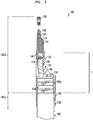
- FIGS. 2 and 3 show a hybrid cable 100.
- FIG. 2 shows details related to fiber-optic cable components of the hybrid cable 100
- FIG. 3 shows details related to power cable components of the hybrid cable 100.
- the cable 100 may include a main body portion 100a and a termination portion 100b at an end of the hybrid cable 100.
- the termination portion 100b may be used to connect the hybrid cable 100 to a RRH (not shown), for example.
- Another termination portion (not shown) may be provided at an opposite end (not shown) of the hybrid cable 100 for connecting the hybrid cable 100 to a base station, for example.
- the hybrid cable 100 may include a plurality of fiber-optic cable pairs 110 ( FIG. 2 ) and a plurality of DC power cable pairs 120 ( FIG. 3 ).
- each of the fiber-optic cable pairs 110 may include a first telecommunication fiber-optic cable 112 and a second telecommunication fiber-optic cable 114.
- each of the power cable pairs 120 may include a first electrical power cable 122 of a first polarity and a second electrical power cable 124 of a second polarity.
- the first and second power cables 122, 124 may be constructed of copper wire, for example.
- the hybrid cable 100 may include six fiber-optic cable pairs 110 and five power cable pairs 120. However, other quantities of fiber-optic cable pairs and power cable pairs are possible.
- the fiber-optic cable pairs 110 and the power cable pairs 120 may be disposed within a weatherproof main, outer jacket 102 and a tubular, conductive armor member 104 in the main body portion 100a of the hybrid cable 100. More specifically, the main jacket 102 may be disposed around the armor member 4, which may be disposed around the fiber-optic cable pairs 110 and the power cable pairs 120.
- the main jacket 102 may be constructed of a non-conductive, flexible material, such as a rubber, polymer, polyester or nylon, for example.
- the armor member 104 may be constructed of corrugated aluminum or another conductive material with a desirable combination of rigidity and flexibility.
- the armor member 104 may provide structural protection to the fiber-optic cables 112, 114 and the power cables 122, 124, and may additionally provide shielding and grounding to the power cables 122, 124.
- the main jacket 102 and the armor member 104 may extend throughout the entire main body portion 100a.
- the fiber-optic cable pairs 110 may be further retained within a fiber-optic cable jacket or channel 106 inside of the armor member 104.
- the fiber-optic cable jacket or channel 106 may be constructed of a non-conductive plastic material, for example.
- the termination portion 100b may include a transition section T immediately adjacent to the main body portion 100a that provides a protective transition region between the main body portion 100a and the termination portion 100b.
- the armor member 104 may extend axially beyond the outer jacket 102 into the transition section T and may terminate part way through the transition section T.
- the fiber-optic cable pairs 110 ( FIG. 2 ) and the power cable pairs 120 ( FIG. 3 ) may extend axially beyond the armor member 104 in the transition section T. As shown in FIG. 2 , the fiber-optic cable pairs 110 may remain within the fiber-optic cable jacket 106 within the transition section T.
- a portion of the fiber-optic cable jacket 106 in the transition section T may be wrapped with a high-temperature tape 136, which in turn may be covered by a securing sleeve or boot 137.
- the securing sleeve or boot 137 may be constructed of a rubber or plastic material, such as flame-retardant polyolefin with adhesive, for example.
- a first, main break-out boot 130 may be attached to the outer jacket 102 at an end of the main body portion 1a of the hybrid cable 1, and may cover the armor member 104, the fiber-optic cable pairs 110 and the power cable pairs 120 at the transition section T.
- a securing sleeve or boot 108 may be disposed over the end of the outer jacket 102 at the end of the main body portion 100a for receiving the main break-out boot 130.
- the securing sleeve or boot 108 may be constructed of a rubber or plastic material, such as flame-retardant polyolefin with adhesive, for example.
- the securing sleeve or boot 108 may cover the armor member 104 in the transition section T.
- the main break-out boot 130 may be fitted onto the securing sleeve or boot 108, and may be retained thereon by an interference fit, adhesive, and/or crimping or clamping means, for example.
- the main break-out boot 130 may include a first port 132 that receives the fiber-optic cable pairs 110, and a plurality of second ports 134, each of which receives one of the power cable pairs 120.
- the main break-out boot may include five, second ports 134.
- the ports 132, 134 may be hollow tubular members.
- the main break-out boot 130 may be constructed of a non-conductive material such as a plastic or rubber material, for example.
- the fiber-optic cable pairs 110 contained within the high-temperature tape 136 and the securing sleeve or boot 137, may extend through the first port 132.
- the tape 136 and the securing sleeve or boot 137 may terminate at or near the exit of the port 132.
- the fiber-optic cable pairs 110 may break out, or extend outside of the main jacket 102, the armor member 104 and the main break-out boot 130 in the termination portion 100b.
- a second, fiber-optic cable break-out boot 140 may be attached to the first port 132 of the main break-out boot 130.
- the second break-out boot 140 may be constructed of a non-conductive material such as a rubber or plastic, for example.
- the second break-out boot 140 may include one or more ports 142 that receive a respective fiber-optic cable pair 110.
- a boot or sleeve 146 may be connected to each port 142 for guiding a respective fiber-optic cable pair 110 as the fiber-optic cable pair 110 exits the port 142.
- the second break-out boot may include six ports 142.
- the fiber-optic cable pairs 110 may break out, or extend separately from respective ports 142 and sleeves 146, and may then be secured to respective fiber-optic connectors 150 for connecting the fiber-optic cable pairs 110 to a RRH, for example.
- each power cable pair 120 may extend through a respective second port 134 of the main break-out boot 130.
- a shielded tube assembly 160 is secured around each power cable pair 120 from a desired area within the transition section T throughout a remainder of the termination portion 100b.
- a segment of the shielded tube assembly 160 may be secured within the second port 134 by an interference or friction fit, for example.
- the shielded tube assembly 160 may include a hollow support tube 162 disposed around the power cable pair 120, a first conductive shielding member 164 disposed around and contacting the support tube 162, a second conductive shielding member 166 disposed around and contacting the first conductive shielding member 164 and a shielded tube assembly jacket 168 disposed around the second conductive shielding member 166.
- the support tube 162 may be constructed of plastic
- the first conductive shielding member 164 may be constructed of aluminum
- the second conductive shielding member 166 may be constructed of tin copper.
- the first conductive shielding member 164 may be constructed of aluminum foil that is wrapped around the support tube 162, and the second conductive shielding member 166 may be constructed of a tin copper braid that is wrapped around the first conductive shielding member 164.
- the hollow support tube 162 is constructed of a conductive material such as aluminum and may form a first conductive shielding member (eliminating the need for a separate first conducting member 164), and the second conductive shielding member 166 may be disposed immediately around the support tube 162.
- the shielded tube assembly jacket 168 may be constructed of rubber, plastic, nylon, polyester or a polymer material, for example.
- the jacket 168 may have a smooth or corrugated surface. According to a preferred embodiment, the jacket 168 may be corrugated to provide a greater bending radius.
- the second conductive shielding member 166 may include a portion 166a extending beyond the support tube 162, the first conductive shielding member 164 and the shielded tube assembly jacket 168 inside the main break-out boot 130.
- the power cable pair 120 may extend through a hole or opening 167 in a sidewall of the portion 166a of the second conductive shielding member 166, and may thereafter extend through a space 166b within the sidewall and inside the support tube 162.
- the portion 166a of the second conductive shielding member 166 may extend alongside the armor member 104 within the securing sleeve or boot 108.
- the portion 166a may be retained in contact with the armor member 104 by one or more conductive fastening members 170 in order to provide continuous electrical shielding and grounding to the power cables 122, 124 throughout the hybrid cable 100.
- the conductive fastening members 170 may be stainless steel bale wires, for example.
- the bale wires 170 may be tightly twisted down to clamp the second conductive shielding member 166 against the armor member 104 such that the bale wires and the second conductive shielding member 166 contact the armor member 104.
- the second conductive shielding member 166 may thereby be secured to the armor member 104, and between the first conductive shielding member 164 and the jacket 168.
- a boot or sleeve 180 may be connected to each port 134 for guiding a respective power cable pair 120.
- the boot or sleeve 180 may be constructed of a non-conductive material, such as a rubber or plastic material, for example.
- the power cable pairs 120 may break out, or extend separately from each other through the respective ports 134 and boots 180 in the termination portion 100b, while being retained within their respective shielded tube assemblies 160.
- the power cable pairs 120 still contained within shielded tube assemblies 160, may then be secured to respective power cable connectors 190 for connecting the power cable pairs 120 to a RRH, for example.
- the hybrid cable 100 may be constructed by a simple, cost-effective method. Generally speaking, the hybrid cable 100 may be constructed by: arranging the armor member 104 to extend in the main body portion 100a; arranging the outer jacket 102 around the armor member 104 in the main body portion 100a; arranging the fiber-optic cable pairs 110 to extend within the armor member 104 and the outer jacket 102 throughout the main body portion 100a, and to extend outside of the armor member 104 and the outer jacket 102 in the termination portion 100b; arranging the power cables pairs 120 to extend within the armor member 104 and the outer jacket 102 throughout the main body portion 100a, and to extend outside of the armor member 104 and the outer jacket 102 in the termination portion 100b; and arranging each shielded tube assembly 160 in the termination portion 100b by attaching each shielded tube assembly 160 to its respective power cable pair 120 to electrically shield the respective power cable pair 120; and electrically grounding each shielded tube assembly 160 to the armor member 104.
- Each shielded tube assembly 160 may attached to its respective power cable pair 120 by: arranging the support tube 162 around the respective power cable pair 120; arranging the first conductive shielding member 164 around the support tube 162; arranging the second conductive shielding member 166 around the first conductive shielding member 164; and arranging the jacket 168 around the second conductive shielding member 166.
- the components 162, 164, 166, 168 of the shielded tube assembly 160 may optionally be fully assembled together prior to arranging the support tube 162 around the respective power cable pair 120.
- the power cable pair 120 may be inserted through the hole 167 in the sidewall of the second conductive shielding member 166 prior to arranging the support tube 162 around the power cable pair 120.
- the disclosed hybrid cable 100 provides effective protection of the fiber optic cables 112, 114 and the power cables 122, 124 from environmental and physical damage, continuous shielding of the power cables 122, 124 and effective grounding of the shielded tube assemblies. Moreover, the features of the cable 100 can be provided without substantially increasing the size/diameter, weight or cost of conventional hybrid cables.
Landscapes
- Physics & Mathematics (AREA)
- General Physics & Mathematics (AREA)
- Optics & Photonics (AREA)
- Engineering & Computer Science (AREA)
- Manufacturing & Machinery (AREA)
- Communication Cables (AREA)
- Insulated Conductors (AREA)
Description
- Known hybrid cables include a plurality of telecommunication fiber-optic cables and a plurality of electrical power cables within a single outer cable jacket. Such hybrid cables may be used as feeder cables in cellular systems to connect base stations (BTSs/NodeBs/eNodeBs) to transceivers or remote radio heads (RRHs), thereby providing power to RRHs and supporting radio frequency (RF) signal transmissions to and from RRHs.
-
FIG. 1 shows a conventional hybrid cable 1. The cable 1 includes amain body portion 1a and atermination portion 1b adjacent to themain body portion 1a at an end of the hybrid cable 1. Thetermination portion 1b may be used to connect the hybrid cable 1 to a transceiver or RRH (not shown), for example. Another termination portion (not shown) may be provided at an opposite end (not shown) of the hybrid cable 1 for connecting the hybrid cable 1 to a base station, for example. - Continuing with reference to
FIG. 1 , the hybrid cable 1 includes a plurality of fiber-optic cable pairs 10 including a first fiber-optic cable 12 and a second fiber-optic cable 14, and a plurality of DCpower cable pairs 20 including afirst power cable 22 of a first polarity and asecond power cable 24 of a second polarity. At themain body portion 1a of the hybrid cable 1, the fiber-optic cable pairs 10 and thepower cable pairs 30 are disposed within amain jacket 2. The plurality of fiber-optic cables 10 are further retained within a fiber-optic cable jacket orchannel 6 inside of themain jacket 2. Anarmor member 4 is disposed within themain jacket 2 throughout themain body portion 1a, and surrounds the fiber-optic cable jacket orchannel 6 and thepower cable pairs 20. - The
termination portion 1b includes a transition section T adjacent to themain body portion 1a that provides a protective transition region between themain body portion 1a and thetermination portion 1b. Thearmor member 4 terminates part way through the transition section T. The fiber-optic cable pairs 10 and thepower cable pairs 20 extend axially beyond thearmor member 4 from the area at which thearmor member 4 terminates. A first, main break-out boot 30 may be attached to theouter jacket 2 at an end of themain body portion 1a of the hybrid cable 1, and may cover thearmor member 4, the fiber-optic cable pairs 10 and thepower cable pairs 20 at the transition section T. The main break-out boot 30 defines one ormore openings 32 through which the fiber-optic cable pairs 10 and thepower cable pairs 20 extend outside of themain jacket 2, thearmor member 4 and the main break-outboot 30 in thetermination portion 1b of the hybrid cable 1. The power cable pairs 20 extend separately from each other at thetermination portion 1b of the hybrid cable 1. A second, fiber-optic cable break-out boot 40 may be attached to an end of the fiber-optic cable jacket 6 at thetermination portion 1b, outside of the opening(s) 32 of the main break-outboot 30. The second break-out boot 40 may include one or more openings 42 through which the fiber-optic cable pairs 10 extend separately from each other outside of the fiber-optic cable jacket orchannel 6. - A fiber-
optic connector 50 may be attached to the end of each fiber-optic cable10 at theend portion 1b of the hybrid cable 1 for connecting each fiber-optic cable pair 10 to a RRH. Each of thepower cable pairs 20 may be connected to a 'RRH by a respective power cable connector (not shown) at theend portion 1b of the hybrid cable 1. Additional shielding and grounding components (not shown) may be added to each of thepower cable pairs 20 at thetermination portion 1b of the hybrid cable 1. - The additional shielding added to each of the
power cable pairs 20 at the termination portion 1 of the hybrid cable 1 presents a challenge with regard to joining thearmor member 4 to the additional shielding to maintain full shielding and grounding throughout the hybrid cable 1. One existing solution to this problem is to usepower cable pairs 20 that are individually shielded throughout their entire lengths. However, providing such full-length shielding is expensive and adds substantial weight to the hybrid cable 1, increases the size (diameter) of the hybrid cable 1, and adds significant expense to manufacturing the hybrid cable 1. - An alternative existing solution to the problem of joining the
armor member 4 to the additional shielding in thetermination portion 1b is to bond shielding components in thetermination portion 1b to thearmor member 4 through welded connections. However, this solution requires welding of dissimilar metals and subjects the heat-sensitive fiber-optic cables 12, 14 to a high amount of heat. - In view of the above, it is desirable to provide an optical electrical hybrid cable that provides effective shielding and grounding of power cables where the power cables extend outside of a main jacket of the hybrid cable. It is further desirable to provide such a hybrid cable using a minimum amount of additional shielding material in order to minimize the size, weight and cost of the hybrid cable.
US4,775,212 relates to a cable for transmitting light signals and electrical signals. In optical fiber cables steel wires are added to strengthen the cable. The invention utilizes the steel wires or any other electrically conductive wires to couple electrical signals or to provide power to remote devices attached to a central station. -
US 5,315,063 discloses a ground connector for grounding a small diameter cable enclosed by an exposed shield employs a collapsible tube formed by a strip of material wound in a spiral shape. A braided connector engages the shield and connects with a ground lead.WO2013/165831 A1 which is part of the prior art according to Article 54(3) EPC discloses a hybrid cable assembly which includes a hybrid cable, tether tubes, and an overmold. The hybrid cable includes both electrical-conductor and fiber-optic elements. Grounding wires connect shielding of the tethers and are coupled to the armor of the hybrid cable. - The disclosure is directed at an improved hybrid cable that can be used, for example, in cellular telecommunication systems to connect base stations (BTSs/NodeBs/eNodeBs) to transceivers or remote radio heads (RRHs). The disclosed hybrid cable includes an improved construction for shielding power cables in a termination portion of the hybrid cable, and grounding shielding components in the termination portion of the hybrid cable. The disclosure further provides a method of constructing the hybrid cable.
- According to an embodiment of the invention, the hybrid cable includes the features of claim 1.
- According to another embodiment, a method of constructing a hybrid cable according to claim 9 is provided.
- Additional features and advantages of the invention will be apparent to those skilled in the art based on the following detailed description and appended drawings.
-
-
FIG. 1 shows an exploded, partial cross-sectional view of a conventional hybrid cable. -
FIGS. 2 and3 show exploded, partial cross-sectional views of a hybrid cable according to an embodiment of the invention, withFIG. 2 providing a detailed view of fiber-optic cable components of the hybrid cable andFIG. 3 providing a detailed view of power cable components of the hybrid cable. -
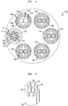
FIG. 4 is a top cross-sectional view of the hybrid cable, at a cross-section taken through fiber-optic cables and the power cables near an exit region of a main break-out boot of the hybrid cable. -
FIG. 5 is a perspective view of the main break-out boot. -
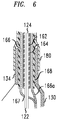
FIG. 6 shows a shielding and grounding assembly for the power cables at a termination region of the hybrid cable. - The following description discloses an exemplary hybrid cable. The hybrid cable may be used for connecting a remote radio head (RRH) to a base station (BTS/NodeB/eNodeB) in a cellular telecommunication network, for example. However, it should be understood that the cable described herein merely represents an exemplary embodiment of the invention, and that variations of the specific embodiment are possible within the scope of the invention. Furthermore, hybrid cables according to the disclosure may be used for connecting equipment or devices other than RRHs and base stations, and may further be used in applications other cellular telecommunication networks.
- It is noted that, throughout the following description and appended drawings, the same reference numerals and characters refer to the same elements, features and structures.
-
FIGS. 2 and3 show ahybrid cable 100.FIG. 2 shows details related to fiber-optic cable components of thehybrid cable 100, whileFIG. 3 shows details related to power cable components of thehybrid cable 100. As shown inFIGS. 2 and3 , thecable 100 may include a main body portion 100a and a termination portion 100b at an end of thehybrid cable 100. The termination portion 100b may be used to connect thehybrid cable 100 to a RRH (not shown), for example. Another termination portion (not shown) may be provided at an opposite end (not shown) of thehybrid cable 100 for connecting thehybrid cable 100 to a base station, for example. - The
hybrid cable 100 may include a plurality of fiber-optic cable pairs 110 (FIG. 2 ) and a plurality of DC power cable pairs 120 (FIG. 3 ). As illustrated inFIG. 2 , each of the fiber-optic cable pairs 110 may include a first telecommunication fiber-optic cable 112 and a second telecommunication fiber-optic cable 114. As illustrated inFIG. 3 , each of thepower cable pairs 120 may include a firstelectrical power cable 122 of a first polarity and a secondelectrical power cable 124 of a second polarity. The first andsecond power cables hybrid cable 100 may include six fiber-optic cable pairs 110 and five power cable pairs 120. However, other quantities of fiber-optic cable pairs and power cable pairs are possible. - Referring to
FIGS. 2 and3 , the fiber-optic cable pairs 110 and the power cable pairs 120 may be disposed within a weatherproof main,outer jacket 102 and a tubular,conductive armor member 104 in the main body portion 100a of thehybrid cable 100. More specifically, themain jacket 102 may be disposed around thearmor member 4, which may be disposed around the fiber-optic cable pairs 110 and the power cable pairs 120. Themain jacket 102 may be constructed of a non-conductive, flexible material, such as a rubber, polymer, polyester or nylon, for example. Thearmor member 104 may be constructed of corrugated aluminum or another conductive material with a desirable combination of rigidity and flexibility. Thearmor member 104 may provide structural protection to the fiber-optic cables power cables power cables main jacket 102 and thearmor member 104 may extend throughout the entire main body portion 100a. - As shown in
FIG. 2 , the fiber-optic cable pairs 110 may be further retained within a fiber-optic cable jacket orchannel 106 inside of thearmor member 104. The fiber-optic cable jacket orchannel 106 may be constructed of a non-conductive plastic material, for example. - Continuing with reference to
FIGS. 2 and3 , the termination portion 100b may include a transition section T immediately adjacent to the main body portion 100a that provides a protective transition region between the main body portion 100a and the termination portion 100b. Thearmor member 104 may extend axially beyond theouter jacket 102 into the transition section T and may terminate part way through the transition section T. The fiber-optic cable pairs 110 (FIG. 2 ) and the power cable pairs 120 (FIG. 3 ) may extend axially beyond thearmor member 104 in the transition section T. As shown inFIG. 2 , the fiber-optic cable pairs 110 may remain within the fiber-optic cable jacket 106 within the transition section T. A portion of the fiber-optic cable jacket 106 in the transition section T may be wrapped with a high-temperature tape 136, which in turn may be covered by a securing sleeve orboot 137. The securing sleeve or boot 137 may be constructed of a rubber or plastic material, such as flame-retardant polyolefin with adhesive, for example. - A first, main break-out
boot 130 may be attached to theouter jacket 102 at an end of themain body portion 1a of the hybrid cable 1, and may cover thearmor member 104, the fiber-optic cable pairs 110 and the power cable pairs 120 at the transition section T. A securing sleeve or boot 108 may be disposed over the end of theouter jacket 102 at the end of the main body portion 100a for receiving the main break-outboot 130. The securing sleeve or boot 108 may be constructed of a rubber or plastic material, such as flame-retardant polyolefin with adhesive, for example. The securing sleeve or boot 108 may cover thearmor member 104 in the transition section T. The main break-outboot 130 may be fitted onto the securing sleeve orboot 108, and may be retained thereon by an interference fit, adhesive, and/or crimping or clamping means, for example. - As shown in
FIGS. 4 and 5 , the main break-outboot 130 may include afirst port 132 that receives the fiber-optic cable pairs 110, and a plurality ofsecond ports 134, each of which receives one of the power cable pairs 120. In the disclosed embodiment including five power cable pairs, the main break-out boot may include five,second ports 134. According to one embodiment, theports boot 130 may be constructed of a non-conductive material such as a plastic or rubber material, for example. - Turning back to
FIG. 2 , the fiber-optic cable pairs 110, contained within the high-temperature tape 136 and the securing sleeve orboot 137, may extend through thefirst port 132. Thetape 136 and the securing sleeve or boot 137 may terminate at or near the exit of theport 132. Upon exiting thefirst port 132, the fiber-optic cable pairs 110 may break out, or extend outside of themain jacket 102, thearmor member 104 and the main break-outboot 130 in the termination portion 100b. - A second, fiber-optic cable break-out
boot 140 may be attached to thefirst port 132 of the main break-outboot 130. The second break-outboot 140 may be constructed of a non-conductive material such as a rubber or plastic, for example. The second break-outboot 140 may include one ormore ports 142 that receive a respective fiber-optic cable pair 110. A boot orsleeve 146 may be connected to eachport 142 for guiding a respective fiber-optic cable pair 110 as the fiber-optic cable pair 110 exits theport 142. In an embodiment including six fiber-optic cable pairs 110, the second break-out boot may include sixports 142. The fiber-optic cable pairs 110 may break out, or extend separately fromrespective ports 142 andsleeves 146, and may then be secured to respective fiber-optic connectors 150 for connecting the fiber-optic cable pairs 110 to a RRH, for example. - Turning to
FIGS. 3 and4 , eachpower cable pair 120 may extend through a respectivesecond port 134 of the main break-outboot 130. As best shown inFIGS. 3 and6 , a shieldedtube assembly 160 is secured around eachpower cable pair 120 from a desired area within the transition section T throughout a remainder of the termination portion 100b. A segment of the shieldedtube assembly 160 may be secured within thesecond port 134 by an interference or friction fit, for example. - Referring to
FIGS. 3 and6 , the shieldedtube assembly 160 may include ahollow support tube 162 disposed around thepower cable pair 120, a first conductive shieldingmember 164 disposed around and contacting thesupport tube 162, a second conductive shieldingmember 166 disposed around and contacting the first conductive shieldingmember 164 and a shieldedtube assembly jacket 168 disposed around the second conductive shieldingmember 166. Thesupport tube 162 may be constructed of plastic, the first conductive shieldingmember 164 may be constructed of aluminum and the second conductive shieldingmember 166 may be constructed of tin copper. The first conductive shieldingmember 164 may be constructed of aluminum foil that is wrapped around thesupport tube 162, and the second conductive shieldingmember 166 may be constructed of a tin copper braid that is wrapped around the first conductive shieldingmember 164. According to the invention, thehollow support tube 162 is constructed of a conductive material such as aluminum and may form a first conductive shielding member (eliminating the need for a separate first conducting member 164), and the second conductive shieldingmember 166 may be disposed immediately around thesupport tube 162. The shieldedtube assembly jacket 168 may be constructed of rubber, plastic, nylon, polyester or a polymer material, for example. Thejacket 168 may have a smooth or corrugated surface. According to a preferred embodiment, thejacket 168 may be corrugated to provide a greater bending radius. Although exemplary materials and constructions are provided herein for the shieldedtube assembly 160, other materials and constructions are possible. - Still referring to
FIGS. 3 and6 , the second conductive shieldingmember 166 may include aportion 166a extending beyond thesupport tube 162, the first conductive shieldingmember 164 and the shieldedtube assembly jacket 168 inside the main break-outboot 130. Thepower cable pair 120 may extend through a hole or opening 167 in a sidewall of theportion 166a of the second conductive shieldingmember 166, and may thereafter extend through a space 166b within the sidewall and inside thesupport tube 162. Theportion 166a of the second conductive shieldingmember 166 may extend alongside thearmor member 104 within the securing sleeve orboot 108. Theportion 166a may be retained in contact with thearmor member 104 by one or moreconductive fastening members 170 in order to provide continuous electrical shielding and grounding to thepower cables hybrid cable 100. Theconductive fastening members 170 may be stainless steel bale wires, for example. Thebale wires 170 may be tightly twisted down to clamp the second conductive shieldingmember 166 against thearmor member 104 such that the bale wires and the second conductive shieldingmember 166 contact thearmor member 104. The second conductive shieldingmember 166 may thereby be secured to thearmor member 104, and between the first conductive shieldingmember 164 and thejacket 168. - Continuing with reference to
FIGS. 3 and6 , a boot orsleeve 180 may be connected to eachport 134 for guiding a respectivepower cable pair 120. The boot orsleeve 180 may be constructed of a non-conductive material, such as a rubber or plastic material, for example. The power cable pairs 120 may break out, or extend separately from each other through therespective ports 134 andboots 180 in the termination portion 100b, while being retained within their respective shieldedtube assemblies 160. The power cable pairs 120, still contained within shieldedtube assemblies 160, may then be secured to respective power cable connectors 190 for connecting the power cable pairs 120 to a RRH, for example. - The
hybrid cable 100 may be constructed by a simple, cost-effective method. Generally speaking, thehybrid cable 100 may be constructed by: arranging thearmor member 104 to extend in the main body portion 100a; arranging theouter jacket 102 around thearmor member 104 in the main body portion 100a; arranging the fiber-optic cable pairs 110 to extend within thearmor member 104 and theouter jacket 102 throughout the main body portion 100a, and to extend outside of thearmor member 104 and theouter jacket 102 in the termination portion 100b; arranging the power cables pairs 120 to extend within thearmor member 104 and theouter jacket 102 throughout the main body portion 100a, and to extend outside of thearmor member 104 and theouter jacket 102 in the termination portion 100b; and arranging each shieldedtube assembly 160 in the termination portion 100b by attaching each shieldedtube assembly 160 to its respectivepower cable pair 120 to electrically shield the respectivepower cable pair 120; and electrically grounding each shieldedtube assembly 160 to thearmor member 104. - Each shielded
tube assembly 160 may attached to its respectivepower cable pair 120 by: arranging thesupport tube 162 around the respectivepower cable pair 120; arranging the first conductive shieldingmember 164 around thesupport tube 162; arranging the second conductive shieldingmember 166 around the first conductive shieldingmember 164; and arranging thejacket 168 around the second conductive shieldingmember 166. Thecomponents tube assembly 160 may optionally be fully assembled together prior to arranging thesupport tube 162 around the respectivepower cable pair 120. Thepower cable pair 120 may be inserted through thehole 167 in the sidewall of the second conductive shieldingmember 166 prior to arranging thesupport tube 162 around thepower cable pair 120. - The disclosed
hybrid cable 100 provides effective protection of thefiber optic cables power cables power cables cable 100 can be provided without substantially increasing the size/diameter, weight or cost of conventional hybrid cables. - It should be understood that the disclosure merely provides exemplary embodiments of the invention. One of ordinary skill in the art will appreciate that changes and variations to the disclosed components, features and methods can be made without departing from the scope of the invention as set forth in the appended claims.
Claims (9)
- A hybrid cable (100), comprising:a main body portion (100a);a termination portion (100b) adjacent to the main body portion (100a) at an end of the hybrid cable for connecting the hybrid cable to a device;a conductive armor member (104) extending in the main body portion (100a);an outer jacket (102) disposed around the conductive armor member (104) in the main body portion (100a);
one or more pairs of fiber-optic cables (112, 114) configured to transmit RF signals, the one or more pairs of fiber-optic cables (112, 114) extending within the conductive armor member (104) and the outer jacket throughout (102) the main body portion, and extending outside of the conductive armor member (104) and the outer jacket (102) in the termination portion;one or more pairs of power cables (122, 124) configured to transmit power signals, the one or more pairs of power cables extending within the conductive armor member (104) and the outer jacket (102) throughout the main body portion(100a), and extending outside of the conductive armor member (104) and the outer jacket (102) in the termination portion (100b);one or more shielded tube assemblies (160) in the termination portion (100b), each shielded tube assembly (160) being attached to a respective pair of power cables (122, 124), and each assembly comprising:an inner conductive support tube (162) that is disposed around the respective pair of power cables (122, 124) and,a conductive shielding member (166) disposed around the inner conductive support tube (162) to electrically shield the support tube (162) and respective power cables (122, 124), the conductive shielding member (166) contacting the armor member (104) to provide grounding for the shielded tube assembly (160). - The hybrid cable of claim 1, wherein each shielded tube assembly (160) comprises:
a jacket member (168) disposed around the conductive shielding member (166). - The hybrid cable (100) of claim 1, wherein the conductive shielding member (166) comprises a braid.
- The hybrid cable (100) of claim 1, wherein:the conductive shielding member (166) comprises a braid; andthe braid is attached to the armor member (104) by at least one conductive wire (170) wrapped around the braid and the armor member, thereby electrically grounding the shielded tube assembly (160).
- The hybrid cable (100) of claim 1, wherein the respective pair of power cables (122, 124) extends through a hole in a sidewall of the conductive shielding member (166), and thereafter extends through a space within the sidewall and into the support tube (162).
- The hybrid cable (100) of claim 1, wherein the conductive support tube (162) is constructed of aluminum and the conductive shielding member (166) is constructed of tin copper.
- The hybrid cable (100) of claim 6, wherein the conductive shielding member (166) comprises a tin copper braid.
- The hybrid cable (100) of claim 1, comprising a boot (108) attached to an end of the outer jacket (102) and disposed around the one or more pairs of fiber-optic cables and the one or more pairs of power cables in a section of the termination portion (100b) immediately adjacent to the main body portion (100a), wherein a segment of each shielded tube assembly is secured in a respective port of the boot (108).
- A method of constructing a hybrid cable, the method comprising:arranging a conductive armor member to extend in a main body portion;arranging an outer jacket around the conductive armor member in the main body portion;arranging one or more pairs of fiber-optic cables to extend within the conductive armor member and the outer jacket throughout the main body portion, and to extend outside of the conductive armor member and the outer jacket in a termination portion of the hybrid cable adjacent to the main body portion;arranging one or more pairs of power cables to extend within the conductive armor member and the outer jacket throughout the main body portion, and to extend outside of the conductive armor member and the outer jacket in the termination portion;arranging one or more shielded tube assemblies in the termination portion by attaching each shielded tube assembly to a respective pair of power cables to electrically shield the respective pair of power cables, each shield tube assembly (160) comprising an inner conductive support tube (162) disposed around the respective pair of power cables (122, 124) and a conductive shielding member (166) disposed around the inner conductive support tube (162), the conductive shielding member (166) extending into the main body portion; andelectrically grounding each shielded tube assembly (160) to the armor member (104) by contacting the conductive shielding member (166) to the armor member (104).
Applications Claiming Priority (2)
| Application Number | Priority Date | Filing Date | Title |
|---|---|---|---|
| US13/931,060 US9299482B2 (en) | 2013-06-28 | 2013-06-28 | Optical electrical hybrid cable |
| PCT/US2014/043761 WO2014209932A1 (en) | 2013-06-28 | 2014-06-24 | Optical electrical hybrid cable |
Publications (2)
| Publication Number | Publication Date |
|---|---|
| EP3014326A1 EP3014326A1 (en) | 2016-05-04 |
| EP3014326B1 true EP3014326B1 (en) | 2019-07-24 |
Family
ID=51179182
Family Applications (1)
| Application Number | Title | Priority Date | Filing Date |
|---|---|---|---|
| EP14739324.3A Active EP3014326B1 (en) | 2013-06-28 | 2014-06-24 | Optical electrical hybrid cable |
Country Status (5)
| Country | Link |
|---|---|
| US (1) | US9299482B2 (en) |
| EP (1) | EP3014326B1 (en) |
| JP (1) | JP6118463B2 (en) |
| CN (1) | CN105492950B (en) |
| WO (1) | WO2014209932A1 (en) |
Families Citing this family (5)
| Publication number | Priority date | Publication date | Assignee | Title |
|---|---|---|---|---|
| EP3510433A1 (en) | 2016-09-06 | 2019-07-17 | CommScope Technologies LLC | Hybrid cable transition assembly |
| CN108400446B (en) * | 2017-02-04 | 2021-05-04 | 中兴通讯股份有限公司 | Photoelectric composite cable |
| TWM572585U (en) * | 2018-09-20 | 2019-01-01 | 大昱光電股份有限公司 | Soft lighting cable |
| CN113838603B (en) * | 2020-06-24 | 2023-05-16 | 华为技术有限公司 | Photoelectric composite cable and communication system |
| CN112505860A (en) * | 2020-12-02 | 2021-03-16 | 中天射频电缆有限公司 | Photoelectric hybrid cable with branching structure and branching method of photoelectric hybrid cable body |
Citations (1)
| Publication number | Priority date | Publication date | Assignee | Title |
|---|---|---|---|---|
| DE202007010626U1 (en) * | 2007-07-31 | 2007-11-08 | Friebe, Michael, Dipl.-Ing. Dr. | Data-energy hybrid cable for use in MRI |
Family Cites Families (11)
| Publication number | Priority date | Publication date | Assignee | Title |
|---|---|---|---|---|
| US4775212A (en) | 1984-03-05 | 1988-10-04 | Honeywell, Inc. | Optical fiber cable |
| US5315063A (en) | 1992-09-10 | 1994-05-24 | Electric Motion Company, Inc. | Ground connector |
| US6169251B1 (en) * | 1997-03-31 | 2001-01-02 | The Whitaker Corporation | Quad cable |
| US6479607B1 (en) * | 2000-11-10 | 2002-11-12 | Henry Milan | Tinted polyvinyl chloride composition and a method for its manufacture and use in a cable |
| US7432446B2 (en) * | 2005-09-28 | 2008-10-07 | Symbol Technologies, Inc. | Coiled electronic article surveillance (EAS) cable |
| US8944411B2 (en) * | 2008-08-29 | 2015-02-03 | Corning Cable Systems Llc | Pulling grip assembly for a fiber optic assembly |
| US8440909B2 (en) * | 2010-07-01 | 2013-05-14 | General Cable Technologies Corporation | Data cable with free stripping water blocking material |
| BR112013008105A2 (en) * | 2010-09-21 | 2016-08-09 | Huber+Suhner Ag | Environmentally sealed cable break assemblies |
| US8842954B2 (en) * | 2012-05-02 | 2014-09-23 | Corning Cable Systems Llc | Cable assembly |
| US9530544B2 (en) * | 2012-11-19 | 2016-12-27 | Commscope Technologies Llc | Shielded electrical conductor furcation assembly |
| US20140140671A1 (en) * | 2012-11-19 | 2014-05-22 | Andrew Llc | Optical fiber / electrical composite cable assembly with sealed breakout kit |
-
2013
- 2013-06-28 US US13/931,060 patent/US9299482B2/en active Active
-
2014
- 2014-06-24 CN CN201480036540.3A patent/CN105492950B/en active Active
- 2014-06-24 WO PCT/US2014/043761 patent/WO2014209932A1/en not_active Ceased
- 2014-06-24 JP JP2016523842A patent/JP6118463B2/en active Active
- 2014-06-24 EP EP14739324.3A patent/EP3014326B1/en active Active
Patent Citations (1)
| Publication number | Priority date | Publication date | Assignee | Title |
|---|---|---|---|---|
| DE202007010626U1 (en) * | 2007-07-31 | 2007-11-08 | Friebe, Michael, Dipl.-Ing. Dr. | Data-energy hybrid cable for use in MRI |
Also Published As
| Publication number | Publication date |
|---|---|
| WO2014209932A1 (en) | 2014-12-31 |
| US9299482B2 (en) | 2016-03-29 |
| US20150003794A1 (en) | 2015-01-01 |
| JP6118463B2 (en) | 2017-04-19 |
| CN105492950B (en) | 2019-12-27 |
| CN105492950A (en) | 2016-04-13 |
| JP2016532255A (en) | 2016-10-13 |
| EP3014326A1 (en) | 2016-05-04 |
Similar Documents
| Publication | Publication Date | Title |
|---|---|---|
| US9679681B2 (en) | Hybrid cable including fiber-optic and electrical-conductor elements | |
| US9299482B2 (en) | Optical electrical hybrid cable | |
| US9069151B2 (en) | Composite cable breakout assembly | |
| US8433165B2 (en) | Optical-electrical hybrid transmission cable | |
| US8948557B2 (en) | Universal remote radio unit fiber optic cable assembly | |
| CN104813211B (en) | Shield electric conductor furcation assemblies | |
| JP5935518B2 (en) | Multi-core cable and method for arranging the same | |
| US20140048302A1 (en) | Differential signal transmission cable and multi-core cable | |
| US20190172611A1 (en) | Differential signal cable assembly | |
| US20180052293A1 (en) | Hybrid conduit system | |
| US20140140669A1 (en) | Rugged furcation tube | |
| TW201401670A (en) | Direct attach cable interface assembly and manufacturing method and direct attach cable interface device thereof | |
| US10700448B2 (en) | Holding structure with insulation cap and insulation cap | |
| KR20150078265A (en) | Optical fiber and power line composite cable | |
| US10234634B2 (en) | Flexible device for distributing hybrid cable and transitioning from trunk cable to jumper cable | |
| US20190140402A1 (en) | Jumper cable with capacitive power enhancement and/or overvoltage protection | |
| GB1592192A (en) | Electric cables | |
| KR102547076B1 (en) | Terminal Connection Structure For Optical Fiber and Power Line Composite Cable | |
| CN112114407A (en) | Improved fiber and power transition design | |
| KR20190076932A (en) | Optical fiber and power line composite cable | |
| CN210667906U (en) | Cable structure, coaxial cable and mobile terminal | |
| AU2017237914B2 (en) | Assembly for distributing trunk cable to furcated cable | |
| CN112217036A (en) | Coaxial cable assembly | |
| US10310203B2 (en) | Grounding structure of optical fiber cable | |
| CN118737560B (en) | A photoelectric composite cable for tethered drones |
Legal Events
| Date | Code | Title | Description |
|---|---|---|---|
| PUAI | Public reference made under article 153(3) epc to a published international application that has entered the european phase |
Free format text: ORIGINAL CODE: 0009012 |
|
| 17P | Request for examination filed |
Effective date: 20160128 |
|
| AK | Designated contracting states |
Kind code of ref document: A1 Designated state(s): AL AT BE BG CH CY CZ DE DK EE ES FI FR GB GR HR HU IE IS IT LI LT LU LV MC MK MT NL NO PL PT RO RS SE SI SK SM TR |
|
| AX | Request for extension of the european patent |
Extension state: BA ME |
|
| DAX | Request for extension of the european patent (deleted) | ||
| GRAP | Despatch of communication of intention to grant a patent |
Free format text: ORIGINAL CODE: EPIDOSNIGR1 |
|
| STAA | Information on the status of an ep patent application or granted ep patent |
Free format text: STATUS: GRANT OF PATENT IS INTENDED |
|
| INTG | Intention to grant announced |
Effective date: 20190110 |
|
| GRAS | Grant fee paid |
Free format text: ORIGINAL CODE: EPIDOSNIGR3 |
|
| GRAA | (expected) grant |
Free format text: ORIGINAL CODE: 0009210 |
|
| STAA | Information on the status of an ep patent application or granted ep patent |
Free format text: STATUS: THE PATENT HAS BEEN GRANTED |
|
| AK | Designated contracting states |
Kind code of ref document: B1 Designated state(s): AL AT BE BG CH CY CZ DE DK EE ES FI FR GB GR HR HU IE IS IT LI LT LU LV MC MK MT NL NO PL PT RO RS SE SI SK SM TR |
|
| REG | Reference to a national code |
Ref country code: GB Ref legal event code: FG4D |
|
| REG | Reference to a national code |
Ref country code: CH Ref legal event code: EP |
|
| REG | Reference to a national code |
Ref country code: DE Ref legal event code: R096 Ref document number: 602014050467 Country of ref document: DE |
|
| REG | Reference to a national code |
Ref country code: AT Ref legal event code: REF Ref document number: 1158868 Country of ref document: AT Kind code of ref document: T Effective date: 20190815 |
|
| REG | Reference to a national code |
Ref country code: IE Ref legal event code: FG4D |
|
| REG | Reference to a national code |
Ref country code: NL Ref legal event code: MP Effective date: 20190724 |
|
| REG | Reference to a national code |
Ref country code: LT Ref legal event code: MG4D |
|
| REG | Reference to a national code |
Ref country code: AT Ref legal event code: MK05 Ref document number: 1158868 Country of ref document: AT Kind code of ref document: T Effective date: 20190724 |
|
| PG25 | Lapsed in a contracting state [announced via postgrant information from national office to epo] |
Ref country code: NO Free format text: LAPSE BECAUSE OF FAILURE TO SUBMIT A TRANSLATION OF THE DESCRIPTION OR TO PAY THE FEE WITHIN THE PRESCRIBED TIME-LIMIT Effective date: 20191024 Ref country code: PT Free format text: LAPSE BECAUSE OF FAILURE TO SUBMIT A TRANSLATION OF THE DESCRIPTION OR TO PAY THE FEE WITHIN THE PRESCRIBED TIME-LIMIT Effective date: 20191125 Ref country code: AT Free format text: LAPSE BECAUSE OF FAILURE TO SUBMIT A TRANSLATION OF THE DESCRIPTION OR TO PAY THE FEE WITHIN THE PRESCRIBED TIME-LIMIT Effective date: 20190724 Ref country code: NL Free format text: LAPSE BECAUSE OF FAILURE TO SUBMIT A TRANSLATION OF THE DESCRIPTION OR TO PAY THE FEE WITHIN THE PRESCRIBED TIME-LIMIT Effective date: 20190724 Ref country code: BG Free format text: LAPSE BECAUSE OF FAILURE TO SUBMIT A TRANSLATION OF THE DESCRIPTION OR TO PAY THE FEE WITHIN THE PRESCRIBED TIME-LIMIT Effective date: 20191024 Ref country code: FI Free format text: LAPSE BECAUSE OF FAILURE TO SUBMIT A TRANSLATION OF THE DESCRIPTION OR TO PAY THE FEE WITHIN THE PRESCRIBED TIME-LIMIT Effective date: 20190724 Ref country code: LT Free format text: LAPSE BECAUSE OF FAILURE TO SUBMIT A TRANSLATION OF THE DESCRIPTION OR TO PAY THE FEE WITHIN THE PRESCRIBED TIME-LIMIT Effective date: 20190724 Ref country code: HR Free format text: LAPSE BECAUSE OF FAILURE TO SUBMIT A TRANSLATION OF THE DESCRIPTION OR TO PAY THE FEE WITHIN THE PRESCRIBED TIME-LIMIT Effective date: 20190724 Ref country code: SE Free format text: LAPSE BECAUSE OF FAILURE TO SUBMIT A TRANSLATION OF THE DESCRIPTION OR TO PAY THE FEE WITHIN THE PRESCRIBED TIME-LIMIT Effective date: 20190724 |
|
| PG25 | Lapsed in a contracting state [announced via postgrant information from national office to epo] |
Ref country code: AL Free format text: LAPSE BECAUSE OF FAILURE TO SUBMIT A TRANSLATION OF THE DESCRIPTION OR TO PAY THE FEE WITHIN THE PRESCRIBED TIME-LIMIT Effective date: 20190724 Ref country code: ES Free format text: LAPSE BECAUSE OF FAILURE TO SUBMIT A TRANSLATION OF THE DESCRIPTION OR TO PAY THE FEE WITHIN THE PRESCRIBED TIME-LIMIT Effective date: 20190724 Ref country code: LV Free format text: LAPSE BECAUSE OF FAILURE TO SUBMIT A TRANSLATION OF THE DESCRIPTION OR TO PAY THE FEE WITHIN THE PRESCRIBED TIME-LIMIT Effective date: 20190724 Ref country code: IS Free format text: LAPSE BECAUSE OF FAILURE TO SUBMIT A TRANSLATION OF THE DESCRIPTION OR TO PAY THE FEE WITHIN THE PRESCRIBED TIME-LIMIT Effective date: 20191124 Ref country code: GR Free format text: LAPSE BECAUSE OF FAILURE TO SUBMIT A TRANSLATION OF THE DESCRIPTION OR TO PAY THE FEE WITHIN THE PRESCRIBED TIME-LIMIT Effective date: 20191025 Ref country code: RS Free format text: LAPSE BECAUSE OF FAILURE TO SUBMIT A TRANSLATION OF THE DESCRIPTION OR TO PAY THE FEE WITHIN THE PRESCRIBED TIME-LIMIT Effective date: 20190724 |
|
| PG25 | Lapsed in a contracting state [announced via postgrant information from national office to epo] |
Ref country code: TR Free format text: LAPSE BECAUSE OF FAILURE TO SUBMIT A TRANSLATION OF THE DESCRIPTION OR TO PAY THE FEE WITHIN THE PRESCRIBED TIME-LIMIT Effective date: 20190724 |
|
| PG25 | Lapsed in a contracting state [announced via postgrant information from national office to epo] |
Ref country code: IT Free format text: LAPSE BECAUSE OF FAILURE TO SUBMIT A TRANSLATION OF THE DESCRIPTION OR TO PAY THE FEE WITHIN THE PRESCRIBED TIME-LIMIT Effective date: 20190724 Ref country code: DK Free format text: LAPSE BECAUSE OF FAILURE TO SUBMIT A TRANSLATION OF THE DESCRIPTION OR TO PAY THE FEE WITHIN THE PRESCRIBED TIME-LIMIT Effective date: 20190724 Ref country code: EE Free format text: LAPSE BECAUSE OF FAILURE TO SUBMIT A TRANSLATION OF THE DESCRIPTION OR TO PAY THE FEE WITHIN THE PRESCRIBED TIME-LIMIT Effective date: 20190724 Ref country code: PL Free format text: LAPSE BECAUSE OF FAILURE TO SUBMIT A TRANSLATION OF THE DESCRIPTION OR TO PAY THE FEE WITHIN THE PRESCRIBED TIME-LIMIT Effective date: 20190724 Ref country code: RO Free format text: LAPSE BECAUSE OF FAILURE TO SUBMIT A TRANSLATION OF THE DESCRIPTION OR TO PAY THE FEE WITHIN THE PRESCRIBED TIME-LIMIT Effective date: 20190724 |
|
| PG25 | Lapsed in a contracting state [announced via postgrant information from national office to epo] |
Ref country code: CZ Free format text: LAPSE BECAUSE OF FAILURE TO SUBMIT A TRANSLATION OF THE DESCRIPTION OR TO PAY THE FEE WITHIN THE PRESCRIBED TIME-LIMIT Effective date: 20190724 Ref country code: SK Free format text: LAPSE BECAUSE OF FAILURE TO SUBMIT A TRANSLATION OF THE DESCRIPTION OR TO PAY THE FEE WITHIN THE PRESCRIBED TIME-LIMIT Effective date: 20190724 Ref country code: IS Free format text: LAPSE BECAUSE OF FAILURE TO SUBMIT A TRANSLATION OF THE DESCRIPTION OR TO PAY THE FEE WITHIN THE PRESCRIBED TIME-LIMIT Effective date: 20200224 Ref country code: SM Free format text: LAPSE BECAUSE OF FAILURE TO SUBMIT A TRANSLATION OF THE DESCRIPTION OR TO PAY THE FEE WITHIN THE PRESCRIBED TIME-LIMIT Effective date: 20190724 |
|
| REG | Reference to a national code |
Ref country code: DE Ref legal event code: R097 Ref document number: 602014050467 Country of ref document: DE |
|
| PLBE | No opposition filed within time limit |
Free format text: ORIGINAL CODE: 0009261 |
|
| STAA | Information on the status of an ep patent application or granted ep patent |
Free format text: STATUS: NO OPPOSITION FILED WITHIN TIME LIMIT |
|
| PG2D | Information on lapse in contracting state deleted |
Ref country code: IS |
|
| 26N | No opposition filed |
Effective date: 20200603 |
|
| PG25 | Lapsed in a contracting state [announced via postgrant information from national office to epo] |
Ref country code: SI Free format text: LAPSE BECAUSE OF FAILURE TO SUBMIT A TRANSLATION OF THE DESCRIPTION OR TO PAY THE FEE WITHIN THE PRESCRIBED TIME-LIMIT Effective date: 20190724 |
|
| PG25 | Lapsed in a contracting state [announced via postgrant information from national office to epo] |
Ref country code: MC Free format text: LAPSE BECAUSE OF FAILURE TO SUBMIT A TRANSLATION OF THE DESCRIPTION OR TO PAY THE FEE WITHIN THE PRESCRIBED TIME-LIMIT Effective date: 20190724 |
|
| REG | Reference to a national code |
Ref country code: CH Ref legal event code: PL |
|
| PG25 | Lapsed in a contracting state [announced via postgrant information from national office to epo] |
Ref country code: LU Free format text: LAPSE BECAUSE OF NON-PAYMENT OF DUE FEES Effective date: 20200624 |
|
| REG | Reference to a national code |
Ref country code: BE Ref legal event code: MM Effective date: 20200630 |
|
| PG25 | Lapsed in a contracting state [announced via postgrant information from national office to epo] |
Ref country code: CH Free format text: LAPSE BECAUSE OF NON-PAYMENT OF DUE FEES Effective date: 20200630 Ref country code: IE Free format text: LAPSE BECAUSE OF NON-PAYMENT OF DUE FEES Effective date: 20200624 Ref country code: LI Free format text: LAPSE BECAUSE OF NON-PAYMENT OF DUE FEES Effective date: 20200630 |
|
| PG25 | Lapsed in a contracting state [announced via postgrant information from national office to epo] |
Ref country code: BE Free format text: LAPSE BECAUSE OF NON-PAYMENT OF DUE FEES Effective date: 20200630 |
|
| PG25 | Lapsed in a contracting state [announced via postgrant information from national office to epo] |
Ref country code: MT Free format text: LAPSE BECAUSE OF FAILURE TO SUBMIT A TRANSLATION OF THE DESCRIPTION OR TO PAY THE FEE WITHIN THE PRESCRIBED TIME-LIMIT Effective date: 20190724 Ref country code: CY Free format text: LAPSE BECAUSE OF FAILURE TO SUBMIT A TRANSLATION OF THE DESCRIPTION OR TO PAY THE FEE WITHIN THE PRESCRIBED TIME-LIMIT Effective date: 20190724 |
|
| PG25 | Lapsed in a contracting state [announced via postgrant information from national office to epo] |
Ref country code: MK Free format text: LAPSE BECAUSE OF FAILURE TO SUBMIT A TRANSLATION OF THE DESCRIPTION OR TO PAY THE FEE WITHIN THE PRESCRIBED TIME-LIMIT Effective date: 20190724 |
|
| REG | Reference to a national code |
Ref country code: DE Ref legal event code: R081 Ref document number: 602014050467 Country of ref document: DE Owner name: RADIO FREQUENCY SYSTEMS GESELLSCHAFT MIT BESCH, DE Free format text: FORMER OWNER: ALCATEL-LUCENT SHANGHAI BELL CO., LTD., SHANGHAI, CN |
|
| REG | Reference to a national code |
Ref country code: GB Ref legal event code: 732E Free format text: REGISTERED BETWEEN 20250417 AND 20250423 |
|
| PGFP | Annual fee paid to national office [announced via postgrant information from national office to epo] |
Ref country code: GB Payment date: 20250617 Year of fee payment: 12 |
|
| PGFP | Annual fee paid to national office [announced via postgrant information from national office to epo] |
Ref country code: FR Payment date: 20250623 Year of fee payment: 12 |
|
| PGFP | Annual fee paid to national office [announced via postgrant information from national office to epo] |
Ref country code: DE Payment date: 20250815 Year of fee payment: 12 |