EP3014124B1 - Servo pump control system and method - Google Patents
Servo pump control system and method Download PDFInfo
- Publication number
- EP3014124B1 EP3014124B1 EP14818733.9A EP14818733A EP3014124B1 EP 3014124 B1 EP3014124 B1 EP 3014124B1 EP 14818733 A EP14818733 A EP 14818733A EP 3014124 B1 EP3014124 B1 EP 3014124B1
- Authority
- EP
- European Patent Office
- Prior art keywords
- electric motor
- pump
- elastic modulus
- rotation speed
- output pressure
- Prior art date
- Legal status (The legal status is an assumption and is not a legal conclusion. Google has not performed a legal analysis and makes no representation as to the accuracy of the status listed.)
- Active
Links
Images


Classifications
-
- F—MECHANICAL ENGINEERING; LIGHTING; HEATING; WEAPONS; BLASTING
- F04—POSITIVE - DISPLACEMENT MACHINES FOR LIQUIDS; PUMPS FOR LIQUIDS OR ELASTIC FLUIDS
- F04B—POSITIVE-DISPLACEMENT MACHINES FOR LIQUIDS; PUMPS
- F04B49/00—Control, e.g. of pump delivery, or pump pressure of, or safety measures for, machines, pumps, or pumping installations, not otherwise provided for, or of interest apart from, groups F04B1/00 - F04B47/00
- F04B49/06—Control using electricity
-
- F—MECHANICAL ENGINEERING; LIGHTING; HEATING; WEAPONS; BLASTING
- F04—POSITIVE - DISPLACEMENT MACHINES FOR LIQUIDS; PUMPS FOR LIQUIDS OR ELASTIC FLUIDS
- F04B—POSITIVE-DISPLACEMENT MACHINES FOR LIQUIDS; PUMPS
- F04B49/00—Control, e.g. of pump delivery, or pump pressure of, or safety measures for, machines, pumps, or pumping installations, not otherwise provided for, or of interest apart from, groups F04B1/00 - F04B47/00
- F04B49/06—Control using electricity
- F04B49/065—Control using electricity and making use of computers
-
- F—MECHANICAL ENGINEERING; LIGHTING; HEATING; WEAPONS; BLASTING
- F04—POSITIVE - DISPLACEMENT MACHINES FOR LIQUIDS; PUMPS FOR LIQUIDS OR ELASTIC FLUIDS
- F04B—POSITIVE-DISPLACEMENT MACHINES FOR LIQUIDS; PUMPS
- F04B17/00—Pumps characterised by combination with, or adaptation to, specific driving engines or motors
- F04B17/03—Pumps characterised by combination with, or adaptation to, specific driving engines or motors driven by electric motors
-
- F—MECHANICAL ENGINEERING; LIGHTING; HEATING; WEAPONS; BLASTING
- F04—POSITIVE - DISPLACEMENT MACHINES FOR LIQUIDS; PUMPS FOR LIQUIDS OR ELASTIC FLUIDS
- F04B—POSITIVE-DISPLACEMENT MACHINES FOR LIQUIDS; PUMPS
- F04B19/00—Machines or pumps having pertinent characteristics not provided for in, or of interest apart from, groups F04B1/00 - F04B17/00
- F04B19/20—Other positive-displacement pumps
- F04B19/22—Other positive-displacement pumps of reciprocating-piston type
-
- F—MECHANICAL ENGINEERING; LIGHTING; HEATING; WEAPONS; BLASTING
- F04—POSITIVE - DISPLACEMENT MACHINES FOR LIQUIDS; PUMPS FOR LIQUIDS OR ELASTIC FLUIDS
- F04B—POSITIVE-DISPLACEMENT MACHINES FOR LIQUIDS; PUMPS
- F04B51/00—Testing machines, pumps, or pumping installations
Definitions
- This invention relates to servo pump control, particularly to a servo pump control system and method.
- CN 201 792 464 U discloses a control system of a servo motor.
- CN 202 742 592 U discloses a servo control system.
- some problems and system limitations exist due to poor controller design coming from lack of thorough understanding of both the hydraulic and electric motor end of the whole electro-hydraulic system.. Key limitations include: there is no auto-commissioning function available for the whole servo pump system; therefore, a try-and-error method needs to be used to manually adjust control parameters continuously, which is a very time-consuming process, increasing labor costs and downtime costs, and meanwhile, it is usually difficult to obtain a good control performance.
- a servo pump control system as defined by the subject-matter of claim 1.
- the servo pump control system and method according to embodiments of the present invention are capable of automatically commissioning parameters of the pressure controller without any manual adjustment, thus saving time, labor costs and downtime costs.
- Fig. 1 it illustrates a servo pump control system 100 according to an embodiment of the present invention.
- the servo pump control system 100 is for controlling a physical system including an electric motor, a pump and a load.
- the dotted box of Fig. 1 shows a physical system model110.
- the physical system model 110 can be simplified as a double integration system, having a feedback of physical states from the output pressure to the load torque. Specifically, a torque T e from the control system is divided by the inertia J of the electric motor and then is converted into the rotation speed ⁇ of the electric motor via an integration 1 s ; the rotation speed ⁇ is multiplied by the elastic modulus K f of the pump and load, to be converted into a derivative p' of the output pressure of the pump; the derivative p' is converted into the output pressure p of the pump via an integration 1 s ; the product T d of the output pressure multiplied by a parameter K T , acting as a disturbance to the torque, is fed back to the input end of the physical system.
- the servo pump control system 100 comprises a pressure controller 101 configured to receive a first control signal, and directly or indirectly provide a second control signal to the electric motor; and the pressure controller 101 further configured to automatically commission at least one parameter without any manual adjustment.
- the first control signal may be a pressure command signal P* set by a user
- the second control signal may be a torque control signal T e
- the pressure controller 101 may further comprise a torque controller (not shown) to provide a torque control signal to the electric motor.
- the torque controller may also be considered outside the pressure controller.
- the design of the torque controller depends only on the electric motor model, so it may be an existing torque controller, and its parameters may be determined at the production time and do not need to be adjusted during the system operation.
- the pressure controller 101 may be any appropriate type of controllers known in the art, such as, a PID controller. However, different from an existing pressure controller, at least one parameter of the pressure controller 101 according to an embodiment of the present invention is automatically commissioned without any manual adjustment, which thus saving time, labor costs etc.
- the automatically commissioning at least one parameter comprises automatically commissioning at least one parameter of the pressure controller 101 based on a received elastic modulus K f of the physical model, for example, automatically commissioning a parameter of a PIC controller included in the pressure controller 101 based on a received elastic modulus K f of the physical model.
- the elastic modulus K f reflects dynamic physical properties of the hydraulic system, thus, commissioning a parameter(s) of the pressure controller 101 based on the elastic modulus K f can make the pressure controller 101 better adapt to a specific hydraulic system and hydraulic application and maintain a good control performance under varying system operation conditions.
- the pressure controller 101 may include a PID controller and a torque controller, and the output of the PID controller after being divided by the elastic modulus K f , is provided to the torque controller as its input. Furthermore, only as an example, the output pressure of the pump from a pressure sensor after being multiplied by the parameter K T is also provided to the torque controller as part of its input. In addition, the output pressure of the pump from the pressure sensor may also be provided to the PID controller as part of its input. It should be pointed out that the description above is only exemplary, rather than limitations to the present invention.
- the pressure controller 101 may commission its parameters with the elastic modulus K f in various other ways, provided only that the use of the elastic modulus K f can make the operation of the controller 101 well reflect the dynamic physical properties of the physical system.
- the elastic modulus K f is automatically identified by the system.
- the servo pump control system 100 further comprises the following optional modules: a speed controller 102 configured to receive a constant speed command, and directly or indirectly provide a third control signal to the electric motor so that the electric motor rotates with a constant speed; and an elastic modulus identification module 103 configured to identify the elastic modulus based on the rotation speed of the electric motor and the output pressure of the pump.
- the speed controller 102 may be any existing or newly developed speed controller, which can make the electric motor rotate with a constant speed after receiving a constant speed command. Furthermore, design of the speed controller 102 depends only on the electric motor model, so its parameters may be determined at the production time of the system and do not need to be adjusted during the system operation.
- the elastic modulus identification module 103 is capable of identifying the elastic modulus K f based on the rotation speed of the electric motor under control of the speed controller 102 and the output pressure of the pump.
- the rotation speed of the electric motor may come from a speed sensor installed at the electric motor or directly come from a speed command.
- the output pressure of the pump may come from a pressure sensor installed at the output end of the pump.
- the pump After the speed controller 102 receives a constant speed command ⁇ , the pump is driven by the electric motor to rotate with a constant speed, and the output pressure of the pump remains constant (working state I) at the beginning of each working cycle of the hydraulic cylinder until the hydraulic cylinder comes to the end. At this time, the constant speed control continues to be applied and the output pressure of the pump will rise linearly with the position of the cylinder (working state II).
- the working state II is a state when the liquid in the hydraulic cylinder is pressed to the end by the piston and the gap in the hydraulic cylinder disappear so that the pressure starts to rise linearly with the position of the piston, and this state may also be called a stable working state.
- Fig. 2 illustrates a graph of the output pressure of the pump varying with time.
- the servo pump control system according to an embodiment of the present invention is described above by referring to the figures. It should be pointed out that the description above is only exemplary, not limitation to the present invention. In other embodiments of the present invention, the system may have more, less or different modules, and the including, connecting and functional relations among these modules may be different from that described and illustrated.
- a servo pump control method may be performed by the servo pump control system described above.
- the above description may be referred to in order to know about the method in more detail.
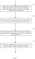
- Fig. 3 illustrates a servo pump control method according to an embodiment of the present invention. As shown by the figure, the method comprises the following steps:
- the automatically commissioning at least one parameter comprises automatically commissioning at least one parameter based on a received elastic modulus of the physical model.
- the method further comprises the following steps:
- the rotation speed of the electric motor comes from a speed sensor or a speed command
- the output pressure of the pump comes from a pressure sensor
- the rotation speed of the electric motor and the output pressure of the pump are respectively the rotation speed of the electric motor and the output pressure of the pump when the pump works in a stable condition, in which the first derivative of the output pressure of the pump has a linear relation with the rotation speed of the electric motor.
- the automatically commissioning at least one parameter based on a received elastic modulus of the physical model comprises automatically commissioning the parameters of a PID controller based on a received elastic modulus of the physical model.
- the servo pump control method is described above by referring to the figures.
- the method may have more, less or different steps, and the including, sequential and functional relations among these steps may be different from that described and illustrated in the present invention.
Landscapes
- Engineering & Computer Science (AREA)
- Mechanical Engineering (AREA)
- General Engineering & Computer Science (AREA)
- Computer Hardware Design (AREA)
- Control Of Positive-Displacement Pumps (AREA)
- Feedback Control In General (AREA)
Description
- This invention relates to servo pump control, particularly to a servo pump control system and method.
-
CN 201 792 464 U discloses a control system of a servo motor.CN 202 742 592 U discloses a servo control system. In current servo pump systems, some problems and system limitations exist due to poor controller design coming from lack of thorough understanding of both the hydraulic and electric motor end of the whole electro-hydraulic system.. Key limitations include: there is no auto-commissioning function available for the whole servo pump system; therefore, a try-and-error method needs to be used to manually adjust control parameters continuously, which is a very time-consuming process, increasing labor costs and downtime costs, and meanwhile, it is usually difficult to obtain a good control performance. - Therefore, a solution of servo pump control that can overcome the defects above is needed in the field.
- In one aspect of the present invention, there is provided a servo pump control system as defined by the subject-matter of claim 1.
- In another aspect of the present invention, there is provided a servo pump control method as defined by the subject-matter of claim 7.
- The servo pump control system and method according to embodiments of the present invention are capable of automatically commissioning parameters of the pressure controller without any manual adjustment, thus saving time, labor costs and downtime costs.
-
-
Fig. 1 illustrates a servo pump control system according to an embodiment of the present invention. -
Fig. 2 illustrates a graph of the output pressure of the pump varying with time. -
Fig. 3 illustrates a servo pump control method according to an embodiment of the present invention. - Embodiments of the present invention are described below by referring to the figures. Numerous details are described below so that those skilled in the art can comprehensively understand and realize the present invention. However, it is apparent to those skilled in the art that the realization of the present invention may not include some of the details. In addition, it should be understood that the present invention is not limited to the described specific embodiments. On the contrary, it is contemplated that the present invention can be realized using any combination of the features and elements described below, no matter whether the features and elements relate to different embodiments or not. Therefore, the following aspects, features, embodiments and advantages are only for illustration, and should not be taken as elements of or limitations to the claims, unless explicitly stated otherwise in the claims.
- Now referring to
Fig. 1 , it illustrates a servopump control system 100 according to an embodiment of the present invention. The servopump control system 100 is for controlling a physical system including an electric motor, a pump and a load. - The dotted box of
Fig. 1 shows a physical system model110. As shown in the figure, thephysical system model 110 can be simplified as a double integration system, having a feedback of physical states from the output pressure to the load torque. Specifically, a torque Te from the control system is divided by the inertia J of the electric motor and then is converted into the rotation speed ω of the electric motor via an integration

- Referring to
Fig. 1 , the servopump control system 100 according to an embodiment of the present invention comprises apressure controller 101 configured to receive a first control signal, and directly or indirectly provide a second control signal to the electric motor; and thepressure controller 101 further configured to automatically commission at least one parameter without any manual adjustment. - The first control signal may be a pressure command signal P* set by a user, and the second control signal may be a torque control signal Te. The
pressure controller 101 may further comprise a torque controller (not shown) to provide a torque control signal to the electric motor. Of course, the torque controller may also be considered outside the pressure controller. The design of the torque controller depends only on the electric motor model, so it may be an existing torque controller, and its parameters may be determined at the production time and do not need to be adjusted during the system operation. - The
pressure controller 101 may be any appropriate type of controllers known in the art, such as, a PID controller. However, different from an existing pressure controller, at least one parameter of thepressure controller 101 according to an embodiment of the present invention is automatically commissioned without any manual adjustment, which thus saving time, labor costs etc. - According to an embodiment of the present invention, the automatically commissioning at least one parameter comprises automatically commissioning at least one parameter of the
pressure controller 101 based on a received elastic modulus Kf of the physical model, for example, automatically commissioning a parameter of a PIC controller included in thepressure controller 101 based on a received elastic modulus Kf of the physical model. The elastic modulus Kf reflects dynamic physical properties of the hydraulic system, thus, commissioning a parameter(s) of thepressure controller 101 based on the elastic modulus Kf can make thepressure controller 101 better adapt to a specific hydraulic system and hydraulic application and maintain a good control performance under varying system operation conditions. - Only as an example, the
pressure controller 101 may include a PID controller and a torque controller, and the output of the PID controller after being divided by the elastic modulus Kf, is provided to the torque controller as its input. Furthermore, only as an example, the output pressure of the pump from a pressure sensor after being multiplied by the parameter KT is also provided to the torque controller as part of its input. In addition, the output pressure of the pump from the pressure sensor may also be provided to the PID controller as part of its input. It should be pointed out that the description above is only exemplary, rather than limitations to the present invention. Thepressure controller 101 may commission its parameters with the elastic modulus Kf in various other ways, provided only that the use of the elastic modulus Kf can make the operation of thecontroller 101 well reflect the dynamic physical properties of the physical system. - According to an embodiment of the present invention, the elastic modulus Kf, is automatically identified by the system. To this end, the servo
pump control system 100 further comprises the following optional modules: aspeed controller 102 configured to receive a constant speed command, and directly or indirectly provide a third control signal to the electric motor so that the electric motor rotates with a constant speed; and an elasticmodulus identification module 103 configured to identify the elastic modulus based on the rotation speed of the electric motor and the output pressure of the pump. - The
speed controller 102 may be any existing or newly developed speed controller, which can make the electric motor rotate with a constant speed after receiving a constant speed command. Furthermore, design of thespeed controller 102 depends only on the electric motor model, so its parameters may be determined at the production time of the system and do not need to be adjusted during the system operation. The elasticmodulus identification module 103 is capable of identifying the elastic modulus Kf based on the rotation speed of the electric motor under control of thespeed controller 102 and the output pressure of the pump. The rotation speed of the electric motor may come from a speed sensor installed at the electric motor or directly come from a speed command. The output pressure of the pump may come from a pressure sensor installed at the output end of the pump. - After the
speed controller 102 receives a constant speed command ω, the pump is driven by the electric motor to rotate with a constant speed, and the output pressure of the pump remains constant (working state I) at the beginning of each working cycle of the hydraulic cylinder until the hydraulic cylinder comes to the end. At this time, the constant speed control continues to be applied and the output pressure of the pump will rise linearly with the position of the cylinder (working state II). The working state II is a state when the liquid in the hydraulic cylinder is pressed to the end by the piston and the gap in the hydraulic cylinder disappear so that the pressure starts to rise linearly with the position of the piston, and this state may also be called a stable working state.Fig. 2 illustrates a graph of the output pressure of the pump varying with time. According to an embodiment of the present invention, the elasticmodulus identification module 103 identifies the elastic modulus Kf as a ratio of the slope of the rising pressure to the rotation speed of the electric motor, i.e., the ratio of the first derivative of the output pressure of the pump (i.e. the tangent of α inFig. 2 ) to the rotation speed of the electric motor, as shown in the following equation:
- In addition, the parameter KT may also be identified as a ratio of a torque command received by the physical system to the output pressure of the pump, as shown in the following equation:

- The servo pump control system according to an embodiment of the present invention is described above by referring to the figures. It should be pointed out that the description above is only exemplary, not limitation to the present invention. In other embodiments of the present invention, the system may have more, less or different modules, and the including, connecting and functional relations among these modules may be different from that described and illustrated.
- In another aspect of the present invention, there is further provided a servo pump control method. The method may be performed by the servo pump control system described above. To be concise, some contents repetitive with the above description are omitted from the following description. Therefore, the above description may be referred to in order to know about the method in more detail.
-
Fig. 3 illustrates a servo pump control method according to an embodiment of the present invention. As shown by the figure, the method comprises the following steps: -
step 303, receiving a first control signal and directly or indirectly providing a second control signal to the electric motor by a pressure controller; and - at
step 304, automatically commissioning at least one parameter by the pressure controller without any manual adjustment. - According to an embodiment of the present invention, the automatically commissioning at least one parameter comprises automatically commissioning at least one parameter based on a received elastic modulus of the physical model.
- According to an embodiment of the present invention, the method further comprises the following steps:
- at
step 301, receiving a constant speed command and directly or indirectly providing a third control signal to the electric motor by a speed controller so that the electric motor rotates with a constant speed; and - at
step 302, identifying the elastic modulus based on the rotation speed of the electric motor and the output pressure of the pump. - According to an embodiment of the present invention, the identifying the elastic modulus comprises calculating the elastic modulus according to the following equation:

- According to an embodiment of the present invention, the rotation speed of the electric motor comes from a speed sensor or a speed command, and the output pressure of the pump comes from a pressure sensor.
- According to an embodiment of the present invention, the rotation speed of the electric motor and the output pressure of the pump are respectively the rotation speed of the electric motor and the output pressure of the pump when the pump works in a stable condition, in which the first derivative of the output pressure of the pump has a linear relation with the rotation speed of the electric motor.
- According to an embodiment of the present invention, the automatically commissioning at least one parameter based on a received elastic modulus of the physical model comprises automatically commissioning the parameters of a PID controller based on a received elastic modulus of the physical model.
- The servo pump control method according to embodiments of the present invention is described above by referring to the figures. In other embodiments of the present invention, the method may have more, less or different steps, and the including, sequential and functional relations among these steps may be different from that described and illustrated in the present invention.
Claims (12)
- A servo pump control system (100) configured to control a physical system including an electric motor, a pump and a load, wherein the control is based on a physical model (110), said servo pump control system (100) comprising:a pressure controller (101) configured to receive a first control signal, and directly or indirectly provide a second control signal to the electric motor; andthe pressure controller further configured to automatically commission at least one parameter without any manual adjustment, wherein the automatically commissioning at least one parameter comprises automatically commissioning at least one parameter based on a received elastic modulus of the physical model.
- The servo pump control system according to claim 1, further comprising:a speed controller (102) configured to receive a constant speed command, and directly or indirectly provide a third control signal to the electric motor so that the electric motor rotates with a constant speed; andan elastic modulus identification module (103) configured to identify the elastic modulus based on the rotation speed of the electric motor and the output pressure of the pump.
- The servo pump control system according to claim 2, wherein the elastic modulus identification module (103) is further configured to calculate the elastic modulus according to the following equation:

- The servo pump control system according to claim 2 or 3, wherein the rotation speed of the electric motor comes from a speed sensor or a speed command, and the output pressure of the pump comes from a pressure sensor.
- The servo pump control system according to claim 2 or 3, wherein the rotation speed of the electric motor and the output pressure of the pump are respectively the rotation speed of the electric motor and the output pressure of the pump when the pump works in a stable condition, in which the first derivative of the output pressure of the pump has a linear relation with the rotation speed of the electric motor.
- The servo pump control system according to claim 1, wherein the automatically commissioning at least one parameter based on a received elastic modulus of the physical model comprises automatically commissioning the parameters of a PID controller based on a received elastic modulus of the physical model.
- A servo pump control method for controlling a physical system including an electric motor, a pump and a load, said servo pump control method comprising:basing the control on a physical model (110),receiving a first control signal and directly or indirectly providing a second control signal to the electric motor by a pressure controller (101); andautomatically commissioning at least one parameter by the pressure controller without any manual adjustment, wherein the automatically commissioning at least one parameter comprises automatically commissioning at least one parameter based on a received elastic modulus of the physical model.
- The servo pump control method according to claim 7, further comprising:receiving a constant speed command and directly or indirectly providing a third control signal to the electric motor by a speed controller (102) so that the electric motor rotates with a constant speed; andidentifying the elastic modulus based on the rotation speed of the electric motor and the output pressure of the pump.
- The servo pump control method according to claim 8, wherein the identifying the elastic modulus comprises calculating the elastic modulus according to the following equation:

- The servo pump control method according to claim 8 or 9, wherein the rotation speed of the electric motor comes from a speed sensor or a speed command, and the output pressure of the pump comes from a pressure sensor.
- The servo pump control method according to claim 8 or 9, wherein the rotation speed of the electric motor and the output pressure of the pump are respectively the rotation speed of the electric motor and the output pressure of the pump when the pump works in a stable condition, in which the first derivative of the output pressure of the pump has a linear relation with the rotation speed of the electric motor.
- The servo pump control method according to claim 7, wherein the automatically commissioning at least one parameter based on a received elastic modulus of the physical model comprises automatically commissioning the parameters of a PID controller based on a received elastic modulus of the physical model.
Applications Claiming Priority (2)
| Application Number | Priority Date | Filing Date | Title |
|---|---|---|---|
| CN201310267723.3A CN104251245B (en) | 2013-06-28 | 2013-06-28 | Servopump controls system and method |
| PCT/CN2014/080980 WO2014206342A1 (en) | 2013-06-28 | 2014-06-27 | Servo pump control system and method |
Publications (3)
| Publication Number | Publication Date |
|---|---|
| EP3014124A1 EP3014124A1 (en) | 2016-05-04 |
| EP3014124A4 EP3014124A4 (en) | 2017-03-08 |
| EP3014124B1 true EP3014124B1 (en) | 2021-05-05 |
Family
ID=52141105
Family Applications (1)
| Application Number | Title | Priority Date | Filing Date |
|---|---|---|---|
| EP14818733.9A Active EP3014124B1 (en) | 2013-06-28 | 2014-06-27 | Servo pump control system and method |
Country Status (4)
| Country | Link |
|---|---|
| US (1) | US10458403B2 (en) |
| EP (1) | EP3014124B1 (en) |
| CN (1) | CN104251245B (en) |
| WO (1) | WO2014206342A1 (en) |
Families Citing this family (1)
| Publication number | Priority date | Publication date | Assignee | Title |
|---|---|---|---|---|
| CN111396400B (en) * | 2020-01-12 | 2022-04-29 | 福建工程学院 | A soft-measurement method for hydraulic cylinder velocity and displacement of a variable-speed single-pump-controlled cylinder closed system under four-quadrant operating conditions |
Family Cites Families (16)
| Publication number | Priority date | Publication date | Assignee | Title |
|---|---|---|---|---|
| US3911677A (en) * | 1971-12-28 | 1975-10-14 | British Industrial Plastics | Injection moulding machines |
| US5899578A (en) * | 1995-12-25 | 1999-05-04 | Sony Corporation | Digital signal processor, processing method, digital signal recording/playback device and digital signal playback method |
| US5971714A (en) * | 1996-05-29 | 1999-10-26 | Graco Inc | Electronic CAM compensation of pressure change of servo controlled pumps |
| US20050084387A1 (en) * | 2003-10-15 | 2005-04-21 | Sauer-Danfoss Inc. | Control system for hydrostatic pump |
| CN101349893B (en) * | 2007-07-18 | 2011-03-16 | 太极光控制软件(北京)有限公司 | Forecast control device of adaptive model |
| CN101737379B (en) * | 2008-11-21 | 2012-08-29 | 鸿富锦精密工业(深圳)有限公司 | Speed-pressure control device for hydraulic equipment |
| JP5395713B2 (en) * | 2010-01-05 | 2014-01-22 | 日立オートモティブシステムズ株式会社 | Vane pump |
| CN102195557B (en) * | 2010-03-12 | 2013-01-23 | 时代新纪元科技集团有限公司 | Pump motor control method and device |
| CN102001167B (en) | 2010-09-07 | 2013-07-24 | 华南理工大学 | Plunger pump type hydraulic injection moulding machine system driven by servo motor and control method thereof |
| CN201792464U (en) * | 2010-09-07 | 2011-04-13 | 华南理工大学 | Control system of servo motor actuating plunger pump type hydraulic injection machine |
| CN202062695U (en) * | 2010-12-30 | 2011-12-07 | 南通国谊锻压机床有限公司 | Hydraulic-machine servo-pump control system |
| KR101294478B1 (en) * | 2011-08-01 | 2013-08-07 | 미쓰비시덴키 가부시키가이샤 | Control device and control method for injection molding machine |
| KR20140099480A (en) * | 2011-11-11 | 2014-08-12 | 애디슨맥키 인크. | Servo motor controlled hydraulic pump unit for tube end forming equipment |
| CN102734277B (en) * | 2012-07-04 | 2015-06-10 | 宁波巴斯顿机械科技有限公司 | High-accuracy and high-efficiency intelligent closed loop servo pump control system |
| CN202742592U (en) * | 2012-07-25 | 2013-02-20 | 宁波千普机械制造有限公司 | Servo control system of rubber injection molding vulcanizing machine |
| CN202805719U (en) * | 2012-08-21 | 2013-03-20 | 武汉华夏精冲技术有限公司 | Fine blanking machine alternating current servo fluid power system |
-
2013
- 2013-06-28 CN CN201310267723.3A patent/CN104251245B/en active Active
-
2014
- 2014-06-27 WO PCT/CN2014/080980 patent/WO2014206342A1/en not_active Ceased
- 2014-06-27 EP EP14818733.9A patent/EP3014124B1/en active Active
- 2014-06-27 US US14/900,044 patent/US10458403B2/en active Active
Also Published As
| Publication number | Publication date |
|---|---|
| US20170268499A1 (en) | 2017-09-21 |
| EP3014124A4 (en) | 2017-03-08 |
| EP3014124A1 (en) | 2016-05-04 |
| CN104251245B (en) | 2016-12-28 |
| US10458403B2 (en) | 2019-10-29 |
| CN104251245A (en) | 2014-12-31 |
| WO2014206342A1 (en) | 2014-12-31 |
Similar Documents
| Publication | Publication Date | Title |
|---|---|---|
| EP2889433B1 (en) | System and method of controlling vehicle of construction equipment | |
| CN103185002A (en) | Electric pump system | |
| CN103334973B (en) | The controlling method of a kind of multi-hydraulic-cylinder synchro system and multi-hydraulic-cylinder synchro system | |
| CN107387599A (en) | The half hitch chalaza self-learning method of wet dual-clutch automatic transmission | |
| US10391729B2 (en) | Servo press, control method, and program | |
| EP2192309B1 (en) | Method and control circuit for regulating a supply of pressure fluid for a hydraulic actuator | |
| CN103163822A (en) | Electronic cam control device and method | |
| CN105269571A (en) | Robot control system having stop function | |
| CN100576116C (en) | Adjustment Method of Parameter Adjustment System of DC Motor Speed PID Control | |
| CN102672926A (en) | Molten gel back pressure control system and method for electrically controlled injection molding machine | |
| JP6233351B2 (en) | Motor control device, motor control method, and motor control program | |
| US10458403B2 (en) | Servo pump control system and method | |
| CN103157851B (en) | Flying shear control system and method | |
| CN203281784U (en) | Flow control system of forging hydraulic press | |
| US11353843B2 (en) | Automatic evaluation of a machine behaviour | |
| CN202626597U (en) | Position adjusting device for servo actuator | |
| EP3173163A1 (en) | Method for controlling or regulating a motion of a tool, hydraulic system, draw cushion press and control device | |
| CN110965607A (en) | Excavator engine control method and system | |
| EP4299904B1 (en) | Method for controlling variable-speed fluid pumps | |
| CN117889215A (en) | Clutch control method, device, controller, vehicle and computer-readable storage medium | |
| CN106194461A (en) | The acquisition methods of engine speed modification method, system and corrected parameter, system | |
| JP5129363B2 (en) | Motor control device | |
| CN113844281B (en) | Rotation speed synchronous control method and device, electronic equipment and storage medium | |
| CN114380007B (en) | Control method, device, equipment and storage medium of sand conveying system | |
| KR101188419B1 (en) | Servo Motor System for Accurately Controlling Torque |
Legal Events
| Date | Code | Title | Description |
|---|---|---|---|
| PUAI | Public reference made under article 153(3) epc to a published international application that has entered the european phase |
Free format text: ORIGINAL CODE: 0009012 |
|
| 17P | Request for examination filed |
Effective date: 20151214 |
|
| AK | Designated contracting states |
Kind code of ref document: A1 Designated state(s): AL AT BE BG CH CY CZ DE DK EE ES FI FR GB GR HR HU IE IS IT LI LT LU LV MC MK MT NL NO PL PT RO RS SE SI SK SM TR |
|
| AX | Request for extension of the european patent |
Extension state: BA ME |
|
| RIN1 | Information on inventor provided before grant (corrected) |
Inventor name: CHENG, XIAOMENG Inventor name: CHEN, YILUN |
|
| DAX | Request for extension of the european patent (deleted) | ||
| A4 | Supplementary search report drawn up and despatched |
Effective date: 20170206 |
|
| RIC1 | Information provided on ipc code assigned before grant |
Ipc: F04B 49/06 20060101AFI20170131BHEP Ipc: F15B 21/08 20060101ALI20170131BHEP Ipc: F04B 17/03 20060101ALI20170131BHEP |
|
| STAA | Information on the status of an ep patent application or granted ep patent |
Free format text: STATUS: EXAMINATION IS IN PROGRESS |
|
| 17Q | First examination report despatched |
Effective date: 20200305 |
|
| RAP1 | Party data changed (applicant data changed or rights of an application transferred) |
Owner name: EATON INTELLIGENT POWER LIMITED |
|
| GRAP | Despatch of communication of intention to grant a patent |
Free format text: ORIGINAL CODE: EPIDOSNIGR1 |
|
| STAA | Information on the status of an ep patent application or granted ep patent |
Free format text: STATUS: GRANT OF PATENT IS INTENDED |
|
| INTG | Intention to grant announced |
Effective date: 20210225 |
|
| GRAS | Grant fee paid |
Free format text: ORIGINAL CODE: EPIDOSNIGR3 |
|
| GRAA | (expected) grant |
Free format text: ORIGINAL CODE: 0009210 |
|
| STAA | Information on the status of an ep patent application or granted ep patent |
Free format text: STATUS: THE PATENT HAS BEEN GRANTED |
|
| AK | Designated contracting states |
Kind code of ref document: B1 Designated state(s): AL AT BE BG CH CY CZ DE DK EE ES FI FR GB GR HR HU IE IS IT LI LT LU LV MC MK MT NL NO PL PT RO RS SE SI SK SM TR |
|
| REG | Reference to a national code |
Ref country code: GB Ref legal event code: FG4D |
|
| REG | Reference to a national code |
Ref country code: CH Ref legal event code: EP |
|
| REG | Reference to a national code |
Ref country code: AT Ref legal event code: REF Ref document number: 1390137 Country of ref document: AT Kind code of ref document: T Effective date: 20210515 |
|
| REG | Reference to a national code |
Ref country code: IE Ref legal event code: FG4D |
|
| REG | Reference to a national code |
Ref country code: DE Ref legal event code: R096 Ref document number: 602014077256 Country of ref document: DE |
|
| REG | Reference to a national code |
Ref country code: LT Ref legal event code: MG9D |
|
| REG | Reference to a national code |
Ref country code: AT Ref legal event code: MK05 Ref document number: 1390137 Country of ref document: AT Kind code of ref document: T Effective date: 20210505 |
|
| PG25 | Lapsed in a contracting state [announced via postgrant information from national office to epo] |
Ref country code: HR Free format text: LAPSE BECAUSE OF FAILURE TO SUBMIT A TRANSLATION OF THE DESCRIPTION OR TO PAY THE FEE WITHIN THE PRESCRIBED TIME-LIMIT Effective date: 20210505 Ref country code: LT Free format text: LAPSE BECAUSE OF FAILURE TO SUBMIT A TRANSLATION OF THE DESCRIPTION OR TO PAY THE FEE WITHIN THE PRESCRIBED TIME-LIMIT Effective date: 20210505 Ref country code: FI Free format text: LAPSE BECAUSE OF FAILURE TO SUBMIT A TRANSLATION OF THE DESCRIPTION OR TO PAY THE FEE WITHIN THE PRESCRIBED TIME-LIMIT Effective date: 20210505 Ref country code: BG Free format text: LAPSE BECAUSE OF FAILURE TO SUBMIT A TRANSLATION OF THE DESCRIPTION OR TO PAY THE FEE WITHIN THE PRESCRIBED TIME-LIMIT Effective date: 20210805 Ref country code: AT Free format text: LAPSE BECAUSE OF FAILURE TO SUBMIT A TRANSLATION OF THE DESCRIPTION OR TO PAY THE FEE WITHIN THE PRESCRIBED TIME-LIMIT Effective date: 20210505 |
|
| PG25 | Lapsed in a contracting state [announced via postgrant information from national office to epo] |
Ref country code: PT Free format text: LAPSE BECAUSE OF FAILURE TO SUBMIT A TRANSLATION OF THE DESCRIPTION OR TO PAY THE FEE WITHIN THE PRESCRIBED TIME-LIMIT Effective date: 20210906 Ref country code: PL Free format text: LAPSE BECAUSE OF FAILURE TO SUBMIT A TRANSLATION OF THE DESCRIPTION OR TO PAY THE FEE WITHIN THE PRESCRIBED TIME-LIMIT Effective date: 20210505 Ref country code: NO Free format text: LAPSE BECAUSE OF FAILURE TO SUBMIT A TRANSLATION OF THE DESCRIPTION OR TO PAY THE FEE WITHIN THE PRESCRIBED TIME-LIMIT Effective date: 20210805 Ref country code: ES Free format text: LAPSE BECAUSE OF FAILURE TO SUBMIT A TRANSLATION OF THE DESCRIPTION OR TO PAY THE FEE WITHIN THE PRESCRIBED TIME-LIMIT Effective date: 20210505 Ref country code: RS Free format text: LAPSE BECAUSE OF FAILURE TO SUBMIT A TRANSLATION OF THE DESCRIPTION OR TO PAY THE FEE WITHIN THE PRESCRIBED TIME-LIMIT Effective date: 20210505 Ref country code: SE Free format text: LAPSE BECAUSE OF FAILURE TO SUBMIT A TRANSLATION OF THE DESCRIPTION OR TO PAY THE FEE WITHIN THE PRESCRIBED TIME-LIMIT Effective date: 20210505 Ref country code: IS Free format text: LAPSE BECAUSE OF FAILURE TO SUBMIT A TRANSLATION OF THE DESCRIPTION OR TO PAY THE FEE WITHIN THE PRESCRIBED TIME-LIMIT Effective date: 20210905 Ref country code: GR Free format text: LAPSE BECAUSE OF FAILURE TO SUBMIT A TRANSLATION OF THE DESCRIPTION OR TO PAY THE FEE WITHIN THE PRESCRIBED TIME-LIMIT Effective date: 20210806 Ref country code: LV Free format text: LAPSE BECAUSE OF FAILURE TO SUBMIT A TRANSLATION OF THE DESCRIPTION OR TO PAY THE FEE WITHIN THE PRESCRIBED TIME-LIMIT Effective date: 20210505 |
|
| REG | Reference to a national code |
Ref country code: NL Ref legal event code: MP Effective date: 20210505 |
|
| PG25 | Lapsed in a contracting state [announced via postgrant information from national office to epo] |
Ref country code: NL Free format text: LAPSE BECAUSE OF FAILURE TO SUBMIT A TRANSLATION OF THE DESCRIPTION OR TO PAY THE FEE WITHIN THE PRESCRIBED TIME-LIMIT Effective date: 20210505 |
|
| REG | Reference to a national code |
Ref country code: GB Ref legal event code: 732E Free format text: REGISTERED BETWEEN 20211210 AND 20211215 |
|
| REG | Reference to a national code |
Ref country code: DE Ref legal event code: R081 Ref document number: 602014077256 Country of ref document: DE Owner name: DANFOSS A/S, DK Free format text: FORMER OWNER: EATON INTELLIGENT POWER LIMITED, DUBLIN, IE Ref country code: DE Ref legal event code: R081 Ref document number: 602014077256 Country of ref document: DE Owner name: DANFOSS POWER SOLUTIONS II TECHNOLOGY A/S, DK Free format text: FORMER OWNER: EATON INTELLIGENT POWER LIMITED, DUBLIN, IE |
|
| PG25 | Lapsed in a contracting state [announced via postgrant information from national office to epo] |
Ref country code: DK Free format text: LAPSE BECAUSE OF FAILURE TO SUBMIT A TRANSLATION OF THE DESCRIPTION OR TO PAY THE FEE WITHIN THE PRESCRIBED TIME-LIMIT Effective date: 20210505 Ref country code: CZ Free format text: LAPSE BECAUSE OF FAILURE TO SUBMIT A TRANSLATION OF THE DESCRIPTION OR TO PAY THE FEE WITHIN THE PRESCRIBED TIME-LIMIT Effective date: 20210505 Ref country code: EE Free format text: LAPSE BECAUSE OF FAILURE TO SUBMIT A TRANSLATION OF THE DESCRIPTION OR TO PAY THE FEE WITHIN THE PRESCRIBED TIME-LIMIT Effective date: 20210505 Ref country code: SK Free format text: LAPSE BECAUSE OF FAILURE TO SUBMIT A TRANSLATION OF THE DESCRIPTION OR TO PAY THE FEE WITHIN THE PRESCRIBED TIME-LIMIT Effective date: 20210505 Ref country code: SM Free format text: LAPSE BECAUSE OF FAILURE TO SUBMIT A TRANSLATION OF THE DESCRIPTION OR TO PAY THE FEE WITHIN THE PRESCRIBED TIME-LIMIT Effective date: 20210505 Ref country code: RO Free format text: LAPSE BECAUSE OF FAILURE TO SUBMIT A TRANSLATION OF THE DESCRIPTION OR TO PAY THE FEE WITHIN THE PRESCRIBED TIME-LIMIT Effective date: 20210505 |
|
| REG | Reference to a national code |
Ref country code: CH Ref legal event code: PL |
|
| REG | Reference to a national code |
Ref country code: DE Ref legal event code: R097 Ref document number: 602014077256 Country of ref document: DE |
|
| REG | Reference to a national code |
Ref country code: BE Ref legal event code: MM Effective date: 20210630 |
|
| PLBE | No opposition filed within time limit |
Free format text: ORIGINAL CODE: 0009261 |
|
| STAA | Information on the status of an ep patent application or granted ep patent |
Free format text: STATUS: NO OPPOSITION FILED WITHIN TIME LIMIT |
|
| PG25 | Lapsed in a contracting state [announced via postgrant information from national office to epo] |
Ref country code: MC Free format text: LAPSE BECAUSE OF FAILURE TO SUBMIT A TRANSLATION OF THE DESCRIPTION OR TO PAY THE FEE WITHIN THE PRESCRIBED TIME-LIMIT Effective date: 20210505 Ref country code: LU Free format text: LAPSE BECAUSE OF NON-PAYMENT OF DUE FEES Effective date: 20210627 |
|
| 26N | No opposition filed |
Effective date: 20220208 |
|
| PG25 | Lapsed in a contracting state [announced via postgrant information from national office to epo] |
Ref country code: LI Free format text: LAPSE BECAUSE OF NON-PAYMENT OF DUE FEES Effective date: 20210630 Ref country code: IE Free format text: LAPSE BECAUSE OF NON-PAYMENT OF DUE FEES Effective date: 20210627 Ref country code: CH Free format text: LAPSE BECAUSE OF NON-PAYMENT OF DUE FEES Effective date: 20210630 |
|
| PG25 | Lapsed in a contracting state [announced via postgrant information from national office to epo] |
Ref country code: IS Free format text: LAPSE BECAUSE OF FAILURE TO SUBMIT A TRANSLATION OF THE DESCRIPTION OR TO PAY THE FEE WITHIN THE PRESCRIBED TIME-LIMIT Effective date: 20210905 Ref country code: AL Free format text: LAPSE BECAUSE OF FAILURE TO SUBMIT A TRANSLATION OF THE DESCRIPTION OR TO PAY THE FEE WITHIN THE PRESCRIBED TIME-LIMIT Effective date: 20210505 |
|
| PG25 | Lapsed in a contracting state [announced via postgrant information from national office to epo] |
Ref country code: IT Free format text: LAPSE BECAUSE OF FAILURE TO SUBMIT A TRANSLATION OF THE DESCRIPTION OR TO PAY THE FEE WITHIN THE PRESCRIBED TIME-LIMIT Effective date: 20210505 Ref country code: BE Free format text: LAPSE BECAUSE OF NON-PAYMENT OF DUE FEES Effective date: 20210630 |
|
| PG25 | Lapsed in a contracting state [announced via postgrant information from national office to epo] |
Ref country code: HU Free format text: LAPSE BECAUSE OF FAILURE TO SUBMIT A TRANSLATION OF THE DESCRIPTION OR TO PAY THE FEE WITHIN THE PRESCRIBED TIME-LIMIT; INVALID AB INITIO Effective date: 20140627 |
|
| PG25 | Lapsed in a contracting state [announced via postgrant information from national office to epo] |
Ref country code: CY Free format text: LAPSE BECAUSE OF FAILURE TO SUBMIT A TRANSLATION OF THE DESCRIPTION OR TO PAY THE FEE WITHIN THE PRESCRIBED TIME-LIMIT Effective date: 20210505 |
|
| P01 | Opt-out of the competence of the unified patent court (upc) registered |
Effective date: 20230617 |
|
| PG25 | Lapsed in a contracting state [announced via postgrant information from national office to epo] |
Ref country code: MK Free format text: LAPSE BECAUSE OF FAILURE TO SUBMIT A TRANSLATION OF THE DESCRIPTION OR TO PAY THE FEE WITHIN THE PRESCRIBED TIME-LIMIT Effective date: 20210505 |
|
| PG25 | Lapsed in a contracting state [announced via postgrant information from national office to epo] |
Ref country code: TR Free format text: LAPSE BECAUSE OF FAILURE TO SUBMIT A TRANSLATION OF THE DESCRIPTION OR TO PAY THE FEE WITHIN THE PRESCRIBED TIME-LIMIT Effective date: 20210505 |
|
| PGFP | Annual fee paid to national office [announced via postgrant information from national office to epo] |
Ref country code: GB Payment date: 20240509 Year of fee payment: 11 |
|
| PGFP | Annual fee paid to national office [announced via postgrant information from national office to epo] |
Ref country code: DE Payment date: 20240507 Year of fee payment: 11 |
|
| PGFP | Annual fee paid to national office [announced via postgrant information from national office to epo] |
Ref country code: FR Payment date: 20240524 Year of fee payment: 11 |
|
| PG25 | Lapsed in a contracting state [announced via postgrant information from national office to epo] |
Ref country code: MT Free format text: LAPSE BECAUSE OF FAILURE TO SUBMIT A TRANSLATION OF THE DESCRIPTION OR TO PAY THE FEE WITHIN THE PRESCRIBED TIME-LIMIT Effective date: 20210505 |
|
| REG | Reference to a national code |
Ref country code: DE Ref legal event code: R081 Ref document number: 602014077256 Country of ref document: DE Owner name: DANFOSS A/S, DK Free format text: FORMER OWNER: DANFOSS POWER SOLUTIONS II TECHNOLOGY A/S, NORDBORG, DK |
|
| REG | Reference to a national code |
Ref country code: DE Ref legal event code: R119 Ref document number: 602014077256 Country of ref document: DE |
|
| GBPC | Gb: european patent ceased through non-payment of renewal fee |
Effective date: 20250627 |
|
| PG25 | Lapsed in a contracting state [announced via postgrant information from national office to epo] |
Ref country code: GB Free format text: LAPSE BECAUSE OF NON-PAYMENT OF DUE FEES Effective date: 20250627 |
|
| PG25 | Lapsed in a contracting state [announced via postgrant information from national office to epo] |
Ref country code: DE Free format text: LAPSE BECAUSE OF NON-PAYMENT OF DUE FEES Effective date: 20260101 |
|
| PG25 | Lapsed in a contracting state [announced via postgrant information from national office to epo] |
Ref country code: FR Free format text: LAPSE BECAUSE OF NON-PAYMENT OF DUE FEES Effective date: 20250630 |