EP3013071A1 - Speaker device - Google Patents
Speaker device Download PDFInfo
- Publication number
- EP3013071A1 EP3013071A1 EP14801780.9A EP14801780A EP3013071A1 EP 3013071 A1 EP3013071 A1 EP 3013071A1 EP 14801780 A EP14801780 A EP 14801780A EP 3013071 A1 EP3013071 A1 EP 3013071A1
- Authority
- EP
- European Patent Office
- Prior art keywords
- frequency range
- speaker
- signal
- speaker unit
- sound
- Prior art date
- Legal status (The legal status is an assumption and is not a legal conclusion. Google has not performed a legal analysis and makes no representation as to the accuracy of the status listed.)
- Granted
Links
Images





Classifications
-
- H—ELECTRICITY
- H04—ELECTRIC COMMUNICATION TECHNIQUE
- H04R—LOUDSPEAKERS, MICROPHONES, GRAMOPHONE PICK-UPS OR LIKE ACOUSTIC ELECTROMECHANICAL TRANSDUCERS; ELECTRIC HEARING AIDS; PUBLIC ADDRESS SYSTEMS
- H04R1/00—Details of transducers, loudspeakers or microphones
- H04R1/02—Casings; Cabinets ; Supports therefor; Mountings therein
-
- H—ELECTRICITY
- H04—ELECTRIC COMMUNICATION TECHNIQUE
- H04R—LOUDSPEAKERS, MICROPHONES, GRAMOPHONE PICK-UPS OR LIKE ACOUSTIC ELECTROMECHANICAL TRANSDUCERS; ELECTRIC HEARING AIDS; PUBLIC ADDRESS SYSTEMS
- H04R1/00—Details of transducers, loudspeakers or microphones
- H04R1/20—Arrangements for obtaining desired frequency or directional characteristics
- H04R1/22—Arrangements for obtaining desired frequency or directional characteristics for obtaining desired frequency characteristic only
- H04R1/26—Spatial arrangements of separate transducers responsive to two or more frequency ranges
-
- H—ELECTRICITY
- H04—ELECTRIC COMMUNICATION TECHNIQUE
- H04R—LOUDSPEAKERS, MICROPHONES, GRAMOPHONE PICK-UPS OR LIKE ACOUSTIC ELECTROMECHANICAL TRANSDUCERS; ELECTRIC HEARING AIDS; PUBLIC ADDRESS SYSTEMS
- H04R1/00—Details of transducers, loudspeakers or microphones
- H04R1/20—Arrangements for obtaining desired frequency or directional characteristics
- H04R1/32—Arrangements for obtaining desired frequency or directional characteristics for obtaining desired directional characteristic only
- H04R1/34—Arrangements for obtaining desired frequency or directional characteristics for obtaining desired directional characteristic only by using a single transducer with sound reflecting, diffracting, directing or guiding means
- H04R1/345—Arrangements for obtaining desired frequency or directional characteristics for obtaining desired directional characteristic only by using a single transducer with sound reflecting, diffracting, directing or guiding means for loudspeakers
-
- H—ELECTRICITY
- H04—ELECTRIC COMMUNICATION TECHNIQUE
- H04R—LOUDSPEAKERS, MICROPHONES, GRAMOPHONE PICK-UPS OR LIKE ACOUSTIC ELECTROMECHANICAL TRANSDUCERS; ELECTRIC HEARING AIDS; PUBLIC ADDRESS SYSTEMS
- H04R3/00—Circuits for transducers
- H04R3/12—Circuits for transducers for distributing signals to two or more loudspeakers
- H04R3/14—Cross-over networks
Definitions
- the present invention relates to a speaker device configured to cause a sound to be reflected off a wall surface of a room and propagate.
- a speaker device including: an elongated housing shaped like a quadrangular prism and standing upright; and a plurality of speaker units provided on all respective four side surfaces of the housing (see Patent Document 1, for example).
- This speaker device delays and adjusts the timing at which each of the speaker units outputs an audio signal, to output a sound beam as a sound wave with directivity.
- This speaker device outputs the sound beams toward a floor and a ceiling of a room to cause the sound beams to be reflected a plurality of times, and accordingly indirect sounds reach a listener from many directions. This configuration achieves an effect in which the listener does not feel an accurate position of the speaker device.
- Speaker devices described below are known as conventional speaker devices.
- the speaker device disclosed in Patent Document 1 is placed in, e.g., a corner of a room, and a sound is emitted from a speaker unit facing walls of the corner, the emitted sound becomes unclear because the sound is muffled in the middle frequency range in the corner of the room.
- the plurality of speaker units are as described above provided on all the respective four side surfaces of the housing in the speaker device disclosed in Patent Document 1. Thus, the side surfaces cannot be decorated, thereby limiting a design of the housing.
- the object of the present invention is to provide a speaker device with sound clarity which is maintained even when a sound is reflected off a wall surface and with high flexibility in design of a housing.
- a speaker device includes: a housing having a back surface formed with an opening, and an upper surface formed with an opening; at least one first speaker unit disposed in the opening of the back surface; at least one second speaker unit disposed in the opening of the upper surface; and an electronic circuit configured to supply a sound signal to the at least one first speaker unit and supply, to the at least one second speaker unit, a partial signal in frequencies of a part of a frequency range of the sound signal.
- the speaker device according to the present invention is placed near a wall of a room, for example.
- a sound emitted from the first speaker unit provided near the back surface is reflected off a wall surface so as to propagate to the room. Even if some frequencies of the emitted sound are attenuated by the reflection, and thereby the sound is muffled, the frequencies can be compensated by the second speaker unit oriented upward.
- the speaker device may further include a reflector disposed on an upper side of the at least one second speaker unit and configured to reflect a sound emitted from the at least one second speaker unit, toward a front side of the housing.
- the electronic circuit may be configured to supply, to the at least one second speaker unit, a signal in frequencies of a middle frequency range of the frequency range of the sound signal.
- the housing may be divided into a plurality of layers at least including: an upper layer box having the opening of the upper surface and accommodating the at least one second speaker unit; a middle layer box having the opening of the back surface and accommodating the at least one first speaker unit; and a lower layer box accommodating the electronic circuit.
- the speaker device may be configured such that the at least one first speaker unit includes a plurality of speaker units to each of which a sound signal of corresponding at least one of a plurality of channels is to be supplied, and the electronic circuit is configured to supply, to the at least one second speaker unit, a signal obtained by extracting the partial signal from the sound signal in each of the plurality of channels and synthesizing the extracted signals.
- the speaker device may further include: a first filter configured to take at least a signal in frequencies of a middle frequency range containing a human voice, out of an audible frequency range of the sound signal; and a second filter configured to take a signal in frequencies of each of a low frequency range and a high frequency range, out of the audible frequency range of the sound signal, wherein the signal in the frequencies of each of the low frequency range and the high frequency range is different from the signal in the frequencies of the middle frequency range, wherein the signal output from the first filter is output to the at least one second speaker unit, and wherein the signal output from the second filter is output to the at least one first speaker unit.
- the speaker device may be configured such that the at least one second speaker unit is a middle-frequency-range speaker with a reduced sound emission characteristic of the low frequency range, and the first filter is a low-pass filter configured to take a signal in frequencies of a frequency range which is less than or equal to the middle frequency range, and the frequencies of the frequency range which is less than or equal to the middle frequency range contains frequencies of the low frequency range.
- the at least one second speaker unit is a middle-frequency-range speaker with a reduced sound emission characteristic of the low frequency range
- the first filter is a low-pass filter configured to take a signal in frequencies of a frequency range which is less than or equal to the middle frequency range, and the frequencies of the frequency range which is less than or equal to the middle frequency range contains frequencies of the low frequency range.
- the speaker device may be configured such that the sound signal is a stereo signal in right and left channels, each of right and left first speaker units as the at least one first speaker unit is configured such that a signal in a corresponding one of the left and right channels is input to said each of right and left first speaker units, and a signal obtained by synthesizing the right and left channels is input to one second speaker unit as the at least one second speaker unit.
- Figs. 1(A)-1(C) are external views of a speaker device according to an embodiment of the present invention.
- Fig. 1(A) is a front elevational view of the speaker device
- Fig. 1(B) is a right side view thereof
- Fig. 1(C) is a rear view thereof.
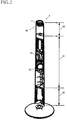
- Fig. 2 is a view illustrating an internal structure of the speaker device.
- Fig. 3 is a rear view of the speaker device, with a speaker grille removed.
- a speaker device 1 includes: a housing 11 for accommodating a plurality of speakers; a base 14 shaped like a round board and provided on a floor surface to support the housing 11; and a pillow 13 shaped like a rod and connecting the housing 11 and the base 14 to each other.
- the housing 11 is supported by the pillow 13 and the base 14 and provided upright in a vertical direction.
- the housing 11 is shaped like a substantially quadrangular prism which slightly tapers in width toward an upper end thereof. That is, the housing 11 has a quadrangular-pyramidal trapezoid shape (a shape obtained by horizontally cutting out a vertex portion or a head portion from a quadrangular pyramid in a plane parallel with a bottom surface of the pyramid), accurately.
- the angle of inclination of a side surface of the housing 11 with respect to the vertical line is 2%.
- the speaker device 1 is installed in a state in which an edge line portion 19 interposed between two side surfaces of the speaker device 1 is located on a front side (a user side).
- the front direction of the speaker device is referred to as a front direction
- the back direction is referred to as a rear direction
- a right and left direction is defined based on a state in which the speaker device 1 is viewed from a user located on a front side.
- the speaker units are oriented not in the front direction but in the rear direction.
- a speaker grille 12 is provided on a back portion of the housing 11.
- the speaker grille 12 need not be provided on a front portion of the speaker device 1, and decorative LEDs 16 are provided on the edge line portion 19 of the front surface of the housing 11.
- the interior of the housing 11 is divided by two partition plates into three spaces in the up and down direction.
- the three spaces include: an upper space as a middle-frequency-range speaker box 30 for accommodating a speaker unit 20; a central space as a stereo speaker box 31 for accommodating speaker units 21, 22; and a lower space as a circuit box 32 for accommodating an electronic circuit 15.
- the stereo speaker box 31 is open in its back surface, and a baffle board 24 is provided in this opening.
- This baffle board 24 is not flat but curved in the right and left direction so as to match the quadrangular prism shape of the housing 11.
- the speaker units 21, 22 are mounted on the baffle board 24, and a bass reflex port 23 is formed in the baffle board 24.
- the speaker unit 21 is a speaker unit for a right channel and mounted so as to be oriented in an obliquely right and rear direction.
- the speaker unit 22 is a speaker unit for a left channel and mounted so as to be oriented in an obliquely left and rear direction.
- the bass reflex port 23 is formed so as to communicate with the interior of the stereo speaker box 31 via a duct.
- the baffle board 24 is covered with the speaker grille 12.
- the speaker grille 12 is formed of a metal mesh and is substantially flush with the housing 11.
- An upper surface of the speaker box 30 for a middle frequency range has an opening in which the speaker unit 20 is mounted so as to be oriented upward.
- a head piece 10 is provided on the upper side of the speaker unit 20 such that sounds emitted from the speaker unit 20 are reflected off the head piece 10 in the front direction.
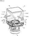
- Fig. 4 is a perspective view of the head piece.
- the head piece 10 includes: a main body 101, as an upper portion, having a sound emission opening 110; a top board 102 disposed on an upper surface of the main body 101; and a skirt 106 as a lower portion.
- the main body 101 is shaped substantially like a cube.
- a bottom board 103 of the head piece 10 has a round opening 103A at its central portion. The diameter of the opening 103A is substantially equal to that of the speaker unit 20.
- a reflector 105 (105A, 105B) is formed in the main body 101.
- This reflector 105 is constituted by two triangle surfaces each connecting between (a) a vertex 105C located at a lower end of sides interposed between two side surfaces 113, 114 serving as a back board 104 and (b) a corresponding one of upper sides of two side surfaces 111, 112 serving as the cutout or the sound emission opening 110. Since the main body 101 is shaped substantially like a cube, each of the left and right surfaces 105A, 105B of the reflector 105 forms an angle of about 45 degrees with respect to a horizontal plane such as the bottom board 103.
- a sound emitting surface of the speaker unit 20 is disposed under the head piece 10 so as to be oriented upward vertically while sharing the central axis with the head piece 10. Also, each surface of the reflector 105 of the head piece 10 faces the sound emitting surface of the speaker unit 20, and the angle of inclination of each surface of the reflector 105 is about 45 degrees.
- a sound emitted upward from the speaker unit 20 is reflected off the reflector 105 and propagates so as to spread in front right and left directions.
- the sound can be reflected off the reflector 105 and propagate so as to spread in the front right and left directions from front portions of the side surfaces of the housing 11 with little loss.
- Fig. 5 is a plan view illustrating an example of an installation position of the speaker device 1.
- the speaker device 1 is installed at, e.g., a corner of a room in a state in which a back portion of the speaker device 1 faces a wall. Since the LEDs 16 are provided decoratively on the front portion of the speaker device 1 without the speaker units and the speaker grille, the speaker device 1 functions also as a decorative interior unlike common speaker devices.
- sounds are emitted from the speaker units 22, 21 for the respective left and right channels. Since the speaker units 21, 22 are oriented in the back direction (i.e., so as to face the wall), the sounds emitted from the speaker units 21, 22 for the respective left and right channels are reflected off a wall surface and propagate in the front direction (i.e., toward a central portion of the room). Sounds in a high frequency range among the sounds emitted from the speaker units 21, 22 travel straight when compared to sounds in the other frequency ranges, and accordingly the sounds emitted from the speaker units 21, 22 are well reflected off the wall.
- a middle frequency range contains human speaking voices and human singing voices, and when sounds in the middle frequency range are reflected off the wall surface, the sounds are attenuated greatly and thereby muffled, resulting in lowered clarity.
- the speaker device 1 extracts components of the middle frequency range from sounds in the left and right channels and emits sounds in the middle frequency range from the speaker unit 20.
- the speaker unit 20 is oriented upward, the emitted sounds in the middle frequency range are well propagated frontward by the head piece 10 provided on the upper side of the speaker unit 20. As a result, the user can clearly listen to the sounds in the low through high frequency ranges without discomfort.
- the electronic circuit 15 is disposed in the circuit box 32 of the housing 11.
- Fig. 6 is a block diagram illustrating a main portion of the electronic circuit 15.
- the electronic circuit 15 includes a controller 50, a signal processor 51, an audio amplifier 52, an input selector 53, a Bluetooth (registered trademark) communication circuit 54, a cable connector 55, and an LED lighting circuit 56.
- the controller 50 is constituted by a microcomputer.
- a light receiving circuit 40 is connected to the controller 50, and this light receiving circuit 40 receives an infrared signal transmitted from an infrared remote control, not shown.
- the light receiving circuit 40 converts the received infrared signal to an electronic signal and inputs it to the controller 50.
- the controller 50 selects an input signal in the input selector 53, adjusts sound quality in the signal processor 51, adjusts a sound volume in the audio amplifier 52, turns on and off the Bluetooth communication circuit 54, sets a password, and controls illumination of the LEDs 16, for example.
- the signal processor 51 adjusts sound quality of an audio signal (a two-channel stereo signal) input from the input selector 53. Also, the signal processor 51 extracts components in the middle frequency range, from signals in the right and left channels, and synthesizes the extracted components to output the obtained signal as an audio signal in a third channel. That is, the signal processor 51 functionally includes band-pass filters 66, 67 and a mixer 68.
- the audio amplifier 52 functionally includes amplifier circuits 64, 65, 69 for three channels which respectively amplify audio signals in the left channel, the right channel, and the middle frequency range.
- the amplifier circuit 64 amplifies a sound signal in the left channel to output it to the speaker 22.
- the amplifier circuit 65 amplifies a sound signal in the right channel to output it to the speaker 21.
- the band-pass filter 66 extracts sound signals in the middle frequency range (e.g., from 100 Hz to 7 kHz) from those in the left channel to output the extracted signals to the mixer 68.
- the band-pass filter 67 extracts sound signals in the middle frequency range from those in the right channel to output the extracted signals to the mixer 68.
- the mixer 68 synthesizes the input sound signals in the middle frequency range in the left channel and the input sound signals in the middle frequency range in the right channel to output the synthesized signals to the amplifier 69.
- the amplifier 69 amplifies the synthesized signals in the middle frequency range to output them to the speaker unit 20. Accordingly, the speaker unit 20 emits the sounds in the middle frequency range in the left and right channels.
- no speaker unit or no speaker grille is provided on the front surface of the housing 11, resulting in increase in flexibility in design for the front surface.
- the middle frequency range to be extracted by the band-pass filter 66 is a frequency range which generally ranges from 100 Hz to 7 kHz, but the middle frequency range is not limited to this frequency range.
- the middle frequency range may be a portion of the frequency range which ranges from 100 Hz to 7 kHz.
- the frequency range to be extracted by the band-pass filter 66 is not limited to the middle frequency range. Even in the case where the speaker unit 20 emits sounds in a range different from the middle frequency range, an effect corresponding to the range can be obtained.
- the speaker units 21, 22 provided on the back surface emit sounds in all the frequency ranges in the present embodiment
- the speaker units 21, 22 can emit sounds based on signals from which frequency range components to be emitted from the speaker unit 20 oriented upward are removed.
- the number of speaker units 21, 22 are provided on the back surface in the above-described embodiment, the number of speaker units is not limited to two. Also, the number of channels of sounds to be emitted is not limited to two channels and may be a single channel (mono), for example.
- the shape of the housing 11 of the speaker device 1 is not limited to the quadrangular-pyramidal trapezoid shape and may be a column shape such as a conical trapezoid shape, a circular cylindrical shape, and a prism shape.
- Each of the speaker units 21, 22 corresponds to a first speaker unit.
- the speaker unit 20 corresponds to a second speaker unit.
- the elements in the present embodiment may be modified, without departing from the spirit of the present invention.
- Common two-way speaker devices are constituted by a speaker unit for middle and low frequency ranges and a speaker unit for a high frequency range (see Patent Document 2, for example).
- sounds in the low frequency range and sounds in the middle frequency range are emitted from the same speaker unit.
- the sounds in the low frequency range and the sounds in the middle frequency range are amplified by the same audio amplifier.
- the middle frequency range is also boosted slightly due to this adjustment, making it difficult to execute control in a state in which the frequency ranges are completely separated from each other.
- the middle frequency range is also boosted due to the effects of the low frequency range, a heavy load is imposed on the audio amplifier, unfortunately.
- the speaker can be provided on the back surface for a design of the front surface.
- a speaker device including: an elongated housing shaped like a quadrangular prism and standing upright; and a plurality of speaker units provided on all respective four side surfaces of the housing (see Patent Document 1, for example).
- This speaker device delays and adjusts the timing at which each of the speaker units outputs an audio signal, to output a sound beam as a sound wave with directivity.
- This speaker device outputs the sound beams toward a floor and a ceiling of a room to cause the sound beams to be reflected a plurality of times, and accordingly indirect sounds reach a listener from many directions. This configuration achieves an effect in which the listener does not feel an accurate position of the speaker device.
- the speaker device disclosed in Patent Document 1 is placed in, e.g., a corner of a room, and a sound is emitted from a speaker unit facing walls of the corner, the emitted sound becomes unclear because the sound is muffled in the middle frequency range in the corner of the room.
- the plurality of speaker units are as described above provided on all the respective four side surfaces of the housing in the speaker device disclosed in Patent Document 1. Thus, the side surfaces cannot be decorated, thereby limiting a design of the housing.
- the second through fourth embodiments are developed to provide a speaker device with (i) improved controllability of sound quality of a two-way speaker device, (ii) clarity which is maintained even when a sound is reflected off a wall surface, and (iii) high flexibility in design of a housing.
- Figs. 7-9 are views for explaining the second embodiment of the present invention.
- Fig. 7 is a block diagram illustrating the speaker device
- Fig. 8 is a view illustrating characteristics of filters
- Fig. 9 illustrates a stereo configuration using two speaker devices.
- the speaker device 500 includes a full-range speaker unit 510 for emitting sounds in the low frequency range and the high frequency range, and a midrange speaker unit 511 for emitting sounds in the middle frequency range.
- the middle frequency range is principally a frequency range which covers human voices and ranges from 100 Hz to 7000 Hz, for example. It is noted that the middle frequency range is not limited to this range.
- the middle frequency range may be a frequency range for a telephone network which ranges from 300 Hz to 3400 Hz.
- the high frequency range is a frequency range higher than the middle frequency range.
- the low frequency range is a frequency range lower than the middle frequency range.
- a lower limit frequency of the middle frequency range will be referred to as "FL"
- an upper limit frequency of the middle frequency range as "FH”.
- the speaker device 500 includes an audio-signal input portion 512, a signal processor 501, a speaker driving portion 502, and speaker units 510, 511.
- the signal processor 501 includes low-pass filters 520, 527, a high-pass filter 521, gain adjusters 523, 524, 528, and an adder 525.
- the speaker driving portion 502 includes amplifiers 526, 529.
- the audio-signal input portion 512 inputs an audio signal and supplies it to the low-pass filters 520, 527 and the high-pass filter 521.
- the low-pass filter 527 passes signals with a frequency lower than or equal to an upper limit frequency FH of the middle frequency range.
- Fig. 8(A) illustrates a frequency response of the low-pass filter 527.
- a gain of an audio signal having passed through the low-pass filter 527 is adjusted by the gain adjuster 528 and amplified by the amplifier 529, and then the audio signal is supplied to the speaker unit 511.
- the audio signal output from the low-pass filter 527 contains components of the low frequency range.
- the speaker unit 511 is for the midrange and cannot emit sounds in the low frequency range as indicated by the broken line in Fig. 8(A) .
- the sound emitted from the speaker unit 511 is such a sound in the middle frequency range that the filter response in Fig. 8(A) is corrected by the broken line.
- the low-pass filter 527 may be a band-pass filter for the middle frequency range.
- the gain adjuster 528 may be included in the low-pass filter 527.
- the low-pass filter 520 passes signals with a frequency lower than or equal to a lower limit frequency FL of the middle frequency range.
- Fig. 8(B) illustrates a frequency response of the low-pass filter 520.
- the curve LPF on the left side indicates a response of the low-pass filter 520.
- a gain of an audio signal in the low frequency range which has passed through the low-pass filter 520 is adjusted by the gain adjuster 523, and then the audio signal is input to the adder 525.
- the high-pass filter 521 passes signals with a frequency higher than or equal to the upper limit frequency FH of the middle frequency range.
- Fig. 8(B) illustrates frequency response of the high-pass filter.
- the curve HPF on the right side indicates a response of the high-pass filter 521.
- a gain of an audio signal in the high frequency range which has passed through the high-pass filter 521 is adjusted by the gain adjuster 524, and then the audio signal is input to the adder 525.
- the adder 525 synthesizes the audio signal in the low frequency range and the audio signal in the high frequency range by adding them together.
- This synthesized audio signal is amplified by the amplifier 526 and supplied to the speaker unit 510.
- the gain adjusters 523, 524 may be included respectively in the low-pass filter 520 and the high-pass filter 521.
- the signal in the component of the low frequency range and the signal in the component of the high frequency range are amplified by the same amplifier, and sounds based on these signals are emitted from the same speaker unit 510, and the signal in the component of the middle frequency range is amplified by the amplifier different from that used for amplifying the signal in the component of the low frequency range, and a sound based on the signal in the component of the middle frequency range is emitted from the speaker unit different from that used for emitting a sound based on the signal in the component of the low frequency range.
- This configuration enables the two-way speaker device to separate the high frequency range, the middle frequency range, and the low frequency range from each other, facilitating independent gain adjustment.
- the speaker unit 510 may be provided on a back surface of the device in this embodiment.
- Fig. 9 is a view illustrating a stereo configuration using two speaker devices 500 each illustrated in Fig. 7 .
- This stereo speaker system includes a speaker device 500L for the left channel and a speaker device 500R for the right channel.
- Fig. 10 is a view illustrating an integral-type stereo speaker device 505 according to a third embodiment of the present invention. This speaker device 505 is configured using a range separation method of the two-way speaker illustrated in Figs. 7-9 .
- the speaker device 505 in Fig. 10 includes: a speaker unit 511C for the middle frequency range which is provided on a front surface of the speaker device 505; and full-range speaker units 510L, 510R (for the left and right channels) provided on a back surface of the speaker device 505.
- the speaker unit 511C, for the middle frequency range, provided on the front surface is oriented frontward but may be oriented in another direction.
- the speaker device may be configured such that the speaker unit is oriented upward, and a reflector may be provided for reflecting emitted sound wave in the front direction.
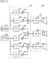
- Fig. 11 is a block diagram illustrating the speaker device 505 illustrated in Fig. 10 .
- the signal processor 501 includes low-pass filters 520L, 520R, 527L, 527R, high-pass filters 521L, 521R, gain adjusters 523L, 523R, 524L, 524R, 528L, 528R, and adders 525L, 525R, 530C.
- the speaker driving portion 502 includes amplifiers 526L, 526R, 529C.
- a left-channel audio-signal input portion 512L inputs an audio signal in the left channel and supplies it to the low-pass filters 520L, 527L and the high-pass filter 521L.
- the low-pass filter 520L passes signals with a frequency lower than or equal to the lower limit frequency FL of the middle frequency range.
- a gain of an audio signal in the low frequency range which has passed through the low-pass filter 520L is adjusted by the gain adjuster 523L, and then the audio signal is input to the adder 525L.
- the high-pass filter 521L passes signals with a frequency higher than or equal to the upper limit frequency FH of the middle frequency range.
- a gain of an audio signal in the high frequency range which has passed through the high-pass filter 521L is adjusted by the gain adjuster 524L, and then the audio signal is input to the adder 525L.
- the adder 525L synthesizes the audio signal in the low frequency range and the audio signal in the high frequency range in the left channel by adding them together.
- This synthesized audio signal is amplified by the amplifier 526L and supplied to the speaker unit 510L.
- the gain adjusters 523L, 524L may be included respectively in the low-pass filter 520L and the high-pass filter 521L.
- a right-channel audio-signal input portion 512R inputs an audio signal in the right channel and supplies it to the low-pass filters 520R, 527R and the high-pass filter 521R.
- the low-pass filter 520R passes signals with a frequency lower than or equal to the lower limit frequency FL of the middle frequency range.
- a gain of an audio signal in the low frequency range which has passed through the low-pass filter 520R is adjusted by the gain adjuster 523R, and then the audio signal is input to the adder 525R.
- the high-pass filter 521R passes signals with a frequency higher than or equal to the upper limit frequency FH of the middle frequency range.
- a gain of an audio signal in the high frequency range which has passed through the high-pass filter 521R is adjusted by the gain adjuster 524R, and then the audio signal is input to the adder 525R.
- the adder 525R synthesizes the audio signal in the low frequency range and the audio signal in the high frequency range in the right channel by adding them together. This synthesized audio signal is amplified by the amplifier 526R and supplied to the speaker unit 510R. It is noted that the gain adjusters 523R, 524R may be included respectively in the low-pass filter 520R and the high-pass filter 521R.
- the low-pass filter 527L for the left channel passes signals with a frequency lower than or equal to the upper limit frequency FH of the middle frequency range.
- a gain of an audio signal having passed through the low-pass filter 527L is adjusted by the gain adjuster 528L, and then the audio signal is input to the adder 530C.
- the low-pass filter 527R for the right channel passes signals with a frequency lower than or equal to the upper limit frequency FH of the middle frequency range.
- a gain of an audio signal having passed through the low-pass filter 527R is adjusted by the gain adjuster 528R, and then the audio signal is input to the adder 530C.
- the adder 530C synthesizes the audio signals in the middle frequency range in the left and right channels by adding them together.
- This synthesized audio signal is amplified by the amplifier 529C and supplied to the speaker unit 511C. It is noted that the gain adjusters 528L, 528R may be included respectively in the low-pass filter 527L and the low-pass filter 527R.
- the audio signal output from the low-pass filters 527L, 527R contains components of the low frequency range, but the speaker unit 511C for the midrange speaker unit cannot emit sounds in the low frequency range.
- the sound emitted from the speaker unit 511C is such a sound in the middle frequency range that the filter response in Fig. 8(A) is corrected by the broken line.
- the low-pass filters 527L, 527R may be a band-pass filter for the middle frequency range.
- This integral stereo speaker illustrated in Figs. 10 and 11 is configured such that the single speaker unit 511C provided on the front surface emits the sound obtained by synthesizing the sounds in the middle frequency range in the left and right channels, and the two speaker units 510L, 510R provided on the back surface emit the sounds in the low frequency range and the high frequency range, separately in the respective left and right channels.
- this speaker device achieves the following effects in addition to those achieved by the speaker device illustrated in Figs. 7-9 .
- Only one small speaker unit is provided on the front surface, or no speaker is provided on the front surface in the case where the speaker unit is oriented upward, resulting in improvement in design of the front surface.
- a large speaker unit can be provided on the back surface, making it possible to emit low sounds of high quality without deterioration of design of the front surface.
- the sounds in the high frequency range are emitted from the two speaker units provided on the back surface, resulting in generation of a right and left stereo feeling using reflection against walls.
- the speaker unit provided on the front surface emits the sounds in the middle frequency range such as human voices, resulting in clear audibility without muffled sounds.
- the one speaker unit 511C for the middle frequency range is provided on the front surface in the embodiment illustrated in Figs. 10 and 11 .
- middle-frequency-range speaker units for the respective left and right channels may be provided on the front surface.
- This speaker device 301 is shaped such that the speaker device 505 illustrated in Figs. 10 and 11 is modified so as to be elongated vertically, and the speaker unit 511C provided on the front surface is modified so as to be provided on the upper side of a housing and oriented upward.
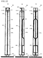
- Figs. 12(A)-12(C) are external views of the speaker device 301.
- Fig. 12(A) is a front elevational view of the speaker device 301
- Fig. 12(B) is a right side view thereof
- Fig. 12(C) is a rear view thereof.
- the speaker device 301 includes: a housing 311 for accommodating a plurality of speakers; a base 314 shaped like a round board and provided on a floor surface to support the housing 311; and a pillow 313 shaped like a rod and connecting the housing 311 and the base 314 to each other.
- the housing 311 is supported by the pillow 313 and the base 314 and provided upright in the vertical direction.
- the housing 311 is shaped like a substantially quadrangular prism which slightly tapers in width toward an upper end thereof. That is, the housing 311 has a quadrangular-pyramidal trapezoid shape (a shape obtained by horizontally cutting out a vertex portion or a head portion from a quadrangular pyramid in a plane parallel with a bottom surface of the pyramid), accurately.
- the angle of inclination of a side surface of the housing 311 with respect to the vertical line is 2%.
- the speaker device 301 is installed in a state in which an edge line portion 319 interposed between two side surfaces of the speaker device 301 is located on a front side (a user side).
- the front direction of the speaker device is referred to as a front direction
- the back direction is referred to as a rear direction
- a right and left direction is defined based on a state in which the speaker device 301 is viewed from a user located on a front side.
- the speaker units 510L, 510R are provided so as to be oriented in the rear direction.
- a speaker grille 312 is provided on a back portion of the housing 311. As a result, the speaker grille 312 need not be provided on a front portion of the speaker device 301.
- the interior of the housing 311 is divided by two partition plates into three spaces in the up and down direction.
- the three spaces include: an upper space as a middle-frequency-range speaker box 330 for accommodating the speaker unit 511C; a central space as a stereo speaker box 331 for accommodating the speaker units 510L, 510R; and a lower space as a circuit box 332 for accommodating an electronic circuit 315.
- An upper surface of the middle-frequency-range speaker box 330 has an opening in which the speaker unit 511C is mounted so as to be oriented upward.
- a head piece 310 is provided on the upper side of the speaker unit 511C such that sounds emitted from the speaker unit 511C are reflected off the head piece 310 in the front direction.
- the head piece 310 in the fourth embodiment has the same construction as that of the head piece 10 illustrated in Fig. 4 .
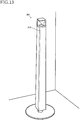
- Fig. 13 is a view illustrating an example of an installation position of the speaker device 301.
- the speaker device 301 is installed at, e.g., a corner of a room in a state in which a back portion of the speaker device 301 faces a wall. Since no speaker units or no speaker grille is provided on the front portion of the speaker device 301, the speaker device 301 functions also as a decorative interior unlike common speaker devices.
- sounds are emitted from the speaker units 510L, 510R for the respective left and right channels. Since the speaker units 510L, 510R are oriented in the back direction (i.e., so as to face the wall), the sounds emitted from the speaker units 510L, 510R for the respective left and right channels are reflected off a wall surface and propagate in the front direction (i.e., toward a central portion of the room).
- Sounds in the high frequency range among the sounds emitted from the speaker units 510L, 510R travel straight when compared to sounds in the other frequency ranges, and accordingly the sounds emitted from the speaker units 510L, 510R are well reflected off the wall, whereby a listener feels a stereo feeling. Since sounds in the low frequency range are emitted with a small amount of spatial impression in audibility, even when the listener listens to the sounds as if the sounds are made near the wall surface, the user (the listener) feels little discomfort.
- the middle frequency range contains human speaking voices and human singing voices, and when sounds in the middle frequency range are reflected off the wall surface, the sounds are attenuated greatly and thereby muffled, resulting in lowered clarity.
- the speaker device 301 extracts components of the middle frequency range from sounds in the left and right channels and emits sounds in the middle frequency range from the speaker unit 511C oriented upward.
- the speaker unit 511C is oriented upward, the emitted sounds in the middle frequency range are well propagated frontward by the head piece 310 provided on the upper side of the speaker unit 511C.
- the user can clearly listen to the sounds in the low through high frequency ranges without discomfort.
- the electronic circuit 315 is disposed in the circuit box 332 of the housing 311.
- Fig. 14 is a block diagram illustrating a main portion of the electronic circuit 315.
- the electronic circuit 315 includes a controller 350, the signal processor 501, an audio amplifier 502, an input selector 353, a Bluetooth (registered trademark) communication circuit 354, and a cable connector 355.
- the controller 350 is constituted by a microcomputer.
- a light receiving circuit 340 is connected to the controller 350, and this light receiving circuit 340 receives an infrared signal transmitted from an infrared remote control, not shown.
- the light receiving circuit 340 converts the received infrared signal to an electronic signal and inputs it to the controller 350.
- the controller 350 selects an input signal in the input selector 353, adjusts sound quality in the signal processor 351, adjusts a sound volume in the audio amplifier 352, turns on and off the Bluetooth communication circuit 354, and sets a password, for example.
- the signal processor 501 is similar in configuration to the signal processor illustrated in Fig. 11 . That is, the signal processor 501 adjusts sound quality of an audio signal (a two-channel stereo signal) input from the input selector 353. Also, the signal processor 501 extracts components in the middle frequency range, from signals in the right and left channels, and synthesizes the extracted components to output the obtained signal as an audio signal in a third channel (i.e., a center channel).
- the speaker driving portion 502 is similar in configuration to the speaker driving portion illustrated in Fig. 11 . That is, the speaker driving portion 502 includes amplifiers 526L, 526R and an amplifier 529 for three channels which respectively amplify audio signals in the left channel, the right channel, and the middle frequency range. The speaker driving portion 502 outputs each of the amplified signals to a corresponding one of the speaker units 510L, 510R and the speaker unit 511C.
- no speaker unit or no speaker grille is provided on the front surface of the housing 311, resulting in increase in flexibility in design for the front surface. Also, sounds in adjacent frequency ranges are not emitted from one speaker unit, enabling gain adjustment for the high frequency range, the middle frequency range, and the low frequency range independently of each other.
- the shape of the housing 311 of the speaker device 301 is not limited to the quadrangular-pyramidal trapezoid shape and may be a column shape such as a conical trapezoid shape, a circular cylindrical shape, and a prism shape.
- the elements in the present embodiment may be modified, without departing from the spirit of the present invention.
- the speaker unit 511C emits the sounds upward in the fourth embodiment, but the present invention is not limited to this construction.
- the speaker unit 511C may be configured to emit the sounds frontward as in the second and third embodiments.
- the speaker device 301 may include: a first filter configured to take at least a signal in a component of the middle frequency range containing a human voice, out of an audible frequency range of the sound signal; a second filter configured to take, out of the audible frequency range of the sound signal, a signal in a component of the low frequency range and a signal in a component of the high frequency range, other than the signal in the component of the middle frequency range; a second speaker unit configured to emit the signal output from the first filter and a first speaker unit configured to emit the signal output from the second filter.
- Speaker Device 10: Head Piece, 11: Housing, 15: Electronic Circuit, 20, 21, 22: Speaker Unit, 30: Middle-frequency-range Speaker Box, 31: Stereo Speaker Box, 32: Circuit Box, 105: Reflector, 301, 500, 505: Speaker Device, 310: Head Piece, 311: Housing, 315: Electronic Circuit, 320, 321, 322: Speaker Unit, 330: Middle-frequency-range Speaker Box, 331: Stereo Speaker Box, 332: Circuit Box, 501: Signal Processor, 502: Speaker Driving Portion
Landscapes
- Health & Medical Sciences (AREA)
- Otolaryngology (AREA)
- Physics & Mathematics (AREA)
- Engineering & Computer Science (AREA)
- Acoustics & Sound (AREA)
- Signal Processing (AREA)
- Stereophonic System (AREA)
- Circuit For Audible Band Transducer (AREA)
Abstract
Description
- The present invention relates to a speaker device configured to cause a sound to be reflected off a wall surface of a room and propagate.
- There is conventionally disclosed an invention of a speaker device including: an elongated housing shaped like a quadrangular prism and standing upright; and a plurality of speaker units provided on all respective four side surfaces of the housing (see
Patent Document 1, for example). This speaker device delays and adjusts the timing at which each of the speaker units outputs an audio signal, to output a sound beam as a sound wave with directivity. This speaker device outputs the sound beams toward a floor and a ceiling of a room to cause the sound beams to be reflected a plurality of times, and accordingly indirect sounds reach a listener from many directions. This configuration achieves an effect in which the listener does not feel an accurate position of the speaker device. Speaker devices described below are known as conventional speaker devices. -
- Patent Document 1:
Japanese Patent Application Publication No. 2007-37058 - Patent Document 2:
Japanese Patent Application Publication No. 11-055780 - In the case where the speaker device disclosed in
Patent Document 1 is placed in, e.g., a corner of a room, and a sound is emitted from a speaker unit facing walls of the corner, the emitted sound becomes unclear because the sound is muffled in the middle frequency range in the corner of the room. Also, the plurality of speaker units are as described above provided on all the respective four side surfaces of the housing in the speaker device disclosed inPatent Document 1. Thus, the side surfaces cannot be decorated, thereby limiting a design of the housing. - Therefore, the object of the present invention is to provide a speaker device with sound clarity which is maintained even when a sound is reflected off a wall surface and with high flexibility in design of a housing.
- A speaker device according to the present invention includes: a housing having a back surface formed with an opening, and an upper surface formed with an opening; at least one first speaker unit disposed in the opening of the back surface; at least one second speaker unit disposed in the opening of the upper surface; and an electronic circuit configured to supply a sound signal to the at least one first speaker unit and supply, to the at least one second speaker unit, a partial signal in frequencies of a part of a frequency range of the sound signal.
- The speaker device according to the present invention is placed near a wall of a room, for example. A sound emitted from the first speaker unit provided near the back surface is reflected off a wall surface so as to propagate to the room. Even if some frequencies of the emitted sound are attenuated by the reflection, and thereby the sound is muffled, the frequencies can be compensated by the second speaker unit oriented upward.
- As another form of the present invention, the speaker device may further include a reflector disposed on an upper side of the at least one second speaker unit and configured to reflect a sound emitted from the at least one second speaker unit, toward a front side of the housing.
- The electronic circuit may be configured to supply, to the at least one second speaker unit, a signal in frequencies of a middle frequency range of the frequency range of the sound signal.
- The housing may be divided into a plurality of layers at least including: an upper layer box having the opening of the upper surface and accommodating the at least one second speaker unit; a middle layer box having the opening of the back surface and accommodating the at least one first speaker unit; and a lower layer box accommodating the electronic circuit.
- The speaker device may be configured such that the at least one first speaker unit includes a plurality of speaker units to each of which a sound signal of corresponding at least one of a plurality of channels is to be supplied, and the electronic circuit is configured to supply, to the at least one second speaker unit, a signal obtained by extracting the partial signal from the sound signal in each of the plurality of channels and synthesizing the extracted signals.
- The speaker device according to the present invention may further include: a first filter configured to take at least a signal in frequencies of a middle frequency range containing a human voice, out of an audible frequency range of the sound signal; and a second filter configured to take a signal in frequencies of each of a low frequency range and a high frequency range, out of the audible frequency range of the sound signal, wherein the signal in the frequencies of each of the low frequency range and the high frequency range is different from the signal in the frequencies of the middle frequency range, wherein the signal output from the first filter is output to the at least one second speaker unit, and wherein the signal output from the second filter is output to the at least one first speaker unit.
- The speaker device may be configured such that the at least one second speaker unit is a middle-frequency-range speaker with a reduced sound emission characteristic of the low frequency range, and the first filter is a low-pass filter configured to take a signal in frequencies of a frequency range which is less than or equal to the middle frequency range, and the frequencies of the frequency range which is less than or equal to the middle frequency range contains frequencies of the low frequency range.
- The speaker device may be configured such that the sound signal is a stereo signal in right and left channels, each of right and left first speaker units as the at least one first speaker unit is configured such that a signal in a corresponding one of the left and right channels is input to said each of right and left first speaker units, and a signal obtained by synthesizing the right and left channels is input to one second speaker unit as the at least one second speaker unit.
- According to the present invention, it is possible to achieve clarity of emitted sounds even in the case where no speaker unit is provided on the front surface to increase flexibility in design of the housing.
-
-
Figs. 1(A) through 1(C) are external views of a speaker device according to a first embodiment of the present invention. -
Fig. 2 is a view illustrating an internal structure of the speaker device. -
Fig. 3 is a rear view of the speaker device, with a speaker grille removed. -
Fig. 4 is a perspective view of a head piece provided on an upper end of the speaker device. -
Fig. 5 is a plan view illustrating an example of an installation position of the speaker device. -
Fig. 6 is a block diagram illustrating an electronic circuit of the speaker device. -
Fig. 7 is a block diagram illustrating a speaker device according to a second embodiment of the present invention. -
Figs. 8(A) and 8(B) are views illustrating characteristics of filters provided on the speaker device according to the second embodiment. -
Fig. 9 is an external view of the speaker device according to the second embodiment in a stereo configuration. -
Fig. 10 is a view illustrating a structure of a speaker device according to a third embodiment of the present invention. -
Fig. 11 is a block diagram illustrating the speaker device according to the third embodiment. -
Fig. 12(A) through 12(C) are external views of the speaker device according to the third embodiment of the present invention. -
Fig. 13 is a view illustrating an example of an installation position of a speaker device according to a fourth embodiment. -
Fig. 14 is a block diagram illustrating an electronic circuit of the speaker device according to the fourth embodiment. - Hereinafter, there will be described speaker devices according to embodiments of the present invention by reference to the drawings.
Figs. 1(A)-1(C) are external views of a speaker device according to an embodiment of the present invention.Fig. 1(A) is a front elevational view of the speaker device,Fig. 1(B) is a right side view thereof, andFig. 1(C) is a rear view thereof.Fig. 2 is a view illustrating an internal structure of the speaker device.Fig. 3 is a rear view of the speaker device, with a speaker grille removed. - A
speaker device 1 according to the embodiment of the present invention includes: ahousing 11 for accommodating a plurality of speakers; abase 14 shaped like a round board and provided on a floor surface to support thehousing 11; and apillow 13 shaped like a rod and connecting thehousing 11 and thebase 14 to each other. Thehousing 11 is supported by thepillow 13 and thebase 14 and provided upright in a vertical direction. - The
housing 11 is shaped like a substantially quadrangular prism which slightly tapers in width toward an upper end thereof. That is, thehousing 11 has a quadrangular-pyramidal trapezoid shape (a shape obtained by horizontally cutting out a vertex portion or a head portion from a quadrangular pyramid in a plane parallel with a bottom surface of the pyramid), accurately. The angle of inclination of a side surface of thehousing 11 with respect to the vertical line is 2%. Thespeaker device 1 is installed in a state in which anedge line portion 19 interposed between two side surfaces of thespeaker device 1 is located on a front side (a user side). In the following explanation, the front direction of the speaker device is referred to as a front direction, and the back direction is referred to as a rear direction. Also, a right and left direction is defined based on a state in which thespeaker device 1 is viewed from a user located on a front side. - In this
speaker device 1, the speaker units are oriented not in the front direction but in the rear direction. Thus, as illustrated inFigs. 1 (B) and 1 (C) , aspeaker grille 12 is provided on a back portion of thehousing 11. As a result, thespeaker grille 12 need not be provided on a front portion of thespeaker device 1, anddecorative LEDs 16 are provided on theedge line portion 19 of the front surface of thehousing 11. - The interior of the
housing 11 is divided by two partition plates into three spaces in the up and down direction. The three spaces include: an upper space as a middle-frequency-range speaker box 30 for accommodating aspeaker unit 20; a central space as astereo speaker box 31 for accommodatingspeaker units circuit box 32 for accommodating an electronic circuit 15. - As illustrated in
Figs. 2 and3 , thestereo speaker box 31 is open in its back surface, and abaffle board 24 is provided in this opening. Thisbaffle board 24 is not flat but curved in the right and left direction so as to match the quadrangular prism shape of thehousing 11. Thespeaker units baffle board 24, and abass reflex port 23 is formed in thebaffle board 24. Thespeaker unit 21 is a speaker unit for a right channel and mounted so as to be oriented in an obliquely right and rear direction. Thespeaker unit 22 is a speaker unit for a left channel and mounted so as to be oriented in an obliquely left and rear direction. Thebass reflex port 23 is formed so as to communicate with the interior of thestereo speaker box 31 via a duct. Thebaffle board 24 is covered with thespeaker grille 12. As illustrated inFig. 1(B) , thespeaker grille 12 is formed of a metal mesh and is substantially flush with thehousing 11. - An upper surface of the
speaker box 30 for a middle frequency range has an opening in which thespeaker unit 20 is mounted so as to be oriented upward. Ahead piece 10 is provided on the upper side of thespeaker unit 20 such that sounds emitted from thespeaker unit 20 are reflected off thehead piece 10 in the front direction. -
Fig. 4 is a perspective view of the head piece. Thehead piece 10 includes: amain body 101, as an upper portion, having asound emission opening 110; atop board 102 disposed on an upper surface of themain body 101; and askirt 106 as a lower portion. Themain body 101 is shaped substantially like a cube. Abottom board 103 of thehead piece 10 has around opening 103A at its central portion. The diameter of theopening 103A is substantially equal to that of thespeaker unit 20. - A reflector 105 (105A, 105B) is formed in the
main body 101. This reflector 105 is constituted by two triangle surfaces each connecting between (a) avertex 105C located at a lower end of sides interposed between twoside surfaces back board 104 and (b) a corresponding one of upper sides of twoside surfaces sound emission opening 110. Since themain body 101 is shaped substantially like a cube, each of the left andright surfaces bottom board 103. - A sound emitting surface of the
speaker unit 20 is disposed under thehead piece 10 so as to be oriented upward vertically while sharing the central axis with thehead piece 10. Also, each surface of the reflector 105 of thehead piece 10 faces the sound emitting surface of thespeaker unit 20, and the angle of inclination of each surface of the reflector 105 is about 45 degrees. Thus, as indicated byarrows 201 inFig. 4 , a sound emitted upward from thespeaker unit 20 is reflected off the reflector 105 and propagates so as to spread in front right and left directions. With this construction, even when the sound is emitted upward from thespeaker unit 20, the sound can be reflected off the reflector 105 and propagate so as to spread in the front right and left directions from front portions of the side surfaces of thehousing 11 with little loss. -
Fig. 5 is a plan view illustrating an example of an installation position of thespeaker device 1. Thespeaker device 1 is installed at, e.g., a corner of a room in a state in which a back portion of thespeaker device 1 faces a wall. Since theLEDs 16 are provided decoratively on the front portion of thespeaker device 1 without the speaker units and the speaker grille, thespeaker device 1 functions also as a decorative interior unlike common speaker devices. - When a sound signal is input to the
speaker device 1, sounds are emitted from thespeaker units speaker units speaker units speaker units speaker units speaker device 1 extracts components of the middle frequency range from sounds in the left and right channels and emits sounds in the middle frequency range from thespeaker unit 20. Although thespeaker unit 20 is oriented upward, the emitted sounds in the middle frequency range are well propagated frontward by thehead piece 10 provided on the upper side of thespeaker unit 20. As a result, the user can clearly listen to the sounds in the low through high frequency ranges without discomfort. - The electronic circuit 15 is disposed in the
circuit box 32 of thehousing 11.Fig. 6 is a block diagram illustrating a main portion of the electronic circuit 15. The electronic circuit 15 includes acontroller 50, asignal processor 51, an audio amplifier 52, aninput selector 53, a Bluetooth (registered trademark)communication circuit 54, acable connector 55, and anLED lighting circuit 56. - The
controller 50 is constituted by a microcomputer. Alight receiving circuit 40 is connected to thecontroller 50, and thislight receiving circuit 40 receives an infrared signal transmitted from an infrared remote control, not shown. Thelight receiving circuit 40 converts the received infrared signal to an electronic signal and inputs it to thecontroller 50. Based on the signals received from thelight receiving circuit 40, thecontroller 50 selects an input signal in theinput selector 53, adjusts sound quality in thesignal processor 51, adjusts a sound volume in the audio amplifier 52, turns on and off theBluetooth communication circuit 54, sets a password, and controls illumination of theLEDs 16, for example. - The
signal processor 51 adjusts sound quality of an audio signal (a two-channel stereo signal) input from theinput selector 53. Also, thesignal processor 51 extracts components in the middle frequency range, from signals in the right and left channels, and synthesizes the extracted components to output the obtained signal as an audio signal in a third channel. That is, thesignal processor 51 functionally includes band-pass filters mixer 68. The audio amplifier 52 functionally includesamplifier circuits amplifier circuit 64 amplifies a sound signal in the left channel to output it to thespeaker 22. Theamplifier circuit 65 amplifies a sound signal in the right channel to output it to thespeaker 21. - The band-
pass filter 66 extracts sound signals in the middle frequency range (e.g., from 100 Hz to 7 kHz) from those in the left channel to output the extracted signals to themixer 68. Likewise, the band-pass filter 67 extracts sound signals in the middle frequency range from those in the right channel to output the extracted signals to themixer 68. Themixer 68 synthesizes the input sound signals in the middle frequency range in the left channel and the input sound signals in the middle frequency range in the right channel to output the synthesized signals to theamplifier 69. Theamplifier 69 amplifies the synthesized signals in the middle frequency range to output them to thespeaker unit 20. Accordingly, thespeaker unit 20 emits the sounds in the middle frequency range in the left and right channels. - As illustrated in
Fig. 5 , in the case where thespeaker device 1 is placed in a state in which its back surface faces the wall of the room, the sounds emitted from thespeaker units speaker unit 20, the sounds in the left and right channels echo clearly in all the frequency ranges. - Also, no speaker unit or no speaker grille is provided on the front surface of the
housing 11, resulting in increase in flexibility in design for the front surface. - The middle frequency range to be extracted by the band-
pass filter 66 is a frequency range which generally ranges from 100 Hz to 7 kHz, but the middle frequency range is not limited to this frequency range. The middle frequency range may be a portion of the frequency range which ranges from 100 Hz to 7 kHz. Also, the frequency range to be extracted by the band-pass filter 66 is not limited to the middle frequency range. Even in the case where thespeaker unit 20 emits sounds in a range different from the middle frequency range, an effect corresponding to the range can be obtained. - While the
speaker units speaker units speaker unit 20 oriented upward are removed. - While the two
speaker units - It is noted that the shape of the
housing 11 of thespeaker device 1 is not limited to the quadrangular-pyramidal trapezoid shape and may be a column shape such as a conical trapezoid shape, a circular cylindrical shape, and a prism shape. - Each of the
speaker units speaker unit 20 corresponds to a second speaker unit. The elements in the present embodiment may be modified, without departing from the spirit of the present invention. - There will be next explained second through fourth embodiments. It is noted that the same reference numerals as used in the first embodiment are used to designate the corresponding elements of the second through fourth embodiments, and an explanation of which is dispensed with. Here, the second through fourth embodiments are created based on the following findings.
- Common two-way speaker devices are constituted by a speaker unit for middle and low frequency ranges and a speaker unit for a high frequency range (see Patent Document 2, for example). In these speaker devices, sounds in the low frequency range and sounds in the middle frequency range are emitted from the same speaker unit. Also, even in the case where different audio amplifiers are provided for different frequency ranges, the sounds in the low frequency range and the sounds in the middle frequency range are amplified by the same audio amplifier. Thus, in the case where a sound quality is adjusted by, e.g., boosting the low frequency range, the middle frequency range is also boosted slightly due to this adjustment, making it difficult to execute control in a state in which the frequency ranges are completely separated from each other. Also, if the middle frequency range is also boosted due to the effects of the low frequency range, a heavy load is imposed on the audio amplifier, unfortunately.
- Incidentally, the speaker can be provided on the back surface for a design of the front surface. For example, there is disclosed an invention of a speaker device including: an elongated housing shaped like a quadrangular prism and standing upright; and a plurality of speaker units provided on all respective four side surfaces of the housing (see
Patent Document 1, for example). This speaker device delays and adjusts the timing at which each of the speaker units outputs an audio signal, to output a sound beam as a sound wave with directivity. This speaker device outputs the sound beams toward a floor and a ceiling of a room to cause the sound beams to be reflected a plurality of times, and accordingly indirect sounds reach a listener from many directions. This configuration achieves an effect in which the listener does not feel an accurate position of the speaker device. - In the case where the speaker device disclosed in
Patent Document 1 is placed in, e.g., a corner of a room, and a sound is emitted from a speaker unit facing walls of the corner, the emitted sound becomes unclear because the sound is muffled in the middle frequency range in the corner of the room. Also, the plurality of speaker units are as described above provided on all the respective four side surfaces of the housing in the speaker device disclosed inPatent Document 1. Thus, the side surfaces cannot be decorated, thereby limiting a design of the housing. - Therefore, the second through fourth embodiments are developed to provide a speaker device with (i) improved controllability of sound quality of a two-way speaker device, (ii) clarity which is maintained even when a sound is reflected off a wall surface, and (iii) high flexibility in design of a housing.
- There will be explained a speaker device according to the second embodiment of the present invention with reference to figures.
Figs. 7-9 are views for explaining the second embodiment of the present invention.Fig. 7 is a block diagram illustrating the speaker device,Fig. 8 is a view illustrating characteristics of filters, andFig. 9 illustrates a stereo configuration using two speaker devices. - The
speaker device 500 includes a full-range speaker unit 510 for emitting sounds in the low frequency range and the high frequency range, and amidrange speaker unit 511 for emitting sounds in the middle frequency range. The middle frequency range is principally a frequency range which covers human voices and ranges from 100 Hz to 7000 Hz, for example. It is noted that the middle frequency range is not limited to this range. For example, the middle frequency range may be a frequency range for a telephone network which ranges from 300 Hz to 3400 Hz. The high frequency range is a frequency range higher than the middle frequency range. The low frequency range is a frequency range lower than the middle frequency range. Hereinafter, a lower limit frequency of the middle frequency range will be referred to as "FL", and an upper limit frequency of the middle frequency range as "FH". - In the block diagram in
Fig. 7 , thespeaker device 500 includes an audio-signal input portion 512, asignal processor 501, aspeaker driving portion 502, andspeaker units signal processor 501 includes low-pass filters pass filter 521, gainadjusters adder 525. Thespeaker driving portion 502 includesamplifiers - The audio-
signal input portion 512 inputs an audio signal and supplies it to the low-pass filters pass filter 521. The low-pass filter 527 passes signals with a frequency lower than or equal to an upper limit frequency FH of the middle frequency range.Fig. 8(A) illustrates a frequency response of the low-pass filter 527. A gain of an audio signal having passed through the low-pass filter 527 is adjusted by thegain adjuster 528 and amplified by theamplifier 529, and then the audio signal is supplied to thespeaker unit 511. The audio signal output from the low-pass filter 527 contains components of the low frequency range. Although this signal is to be supplied to thespeaker unit 511, thespeaker unit 511 is for the midrange and cannot emit sounds in the low frequency range as indicated by the broken line inFig. 8(A) . Thus, the sound emitted from thespeaker unit 511 is such a sound in the middle frequency range that the filter response inFig. 8(A) is corrected by the broken line. It is noted that the low-pass filter 527 may be a band-pass filter for the middle frequency range. Thegain adjuster 528 may be included in the low-pass filter 527. - The low-
pass filter 520 passes signals with a frequency lower than or equal to a lower limit frequency FL of the middle frequency range.Fig. 8(B) illustrates a frequency response of the low-pass filter 520. The curve LPF on the left side indicates a response of the low-pass filter 520. A gain of an audio signal in the low frequency range which has passed through the low-pass filter 520 is adjusted by thegain adjuster 523, and then the audio signal is input to theadder 525. The high-pass filter 521 passes signals with a frequency higher than or equal to the upper limit frequency FH of the middle frequency range.Fig. 8(B) illustrates frequency response of the high-pass filter. The curve HPF on the right side indicates a response of the high-pass filter 521. A gain of an audio signal in the high frequency range which has passed through the high-pass filter 521 is adjusted by thegain adjuster 524, and then the audio signal is input to theadder 525. Theadder 525 synthesizes the audio signal in the low frequency range and the audio signal in the high frequency range by adding them together. This synthesized audio signal is amplified by theamplifier 526 and supplied to thespeaker unit 510. It is noted that thegain adjusters pass filter 520 and the high-pass filter 521. - As described above, the signal in the component of the low frequency range and the signal in the component of the high frequency range are amplified by the same amplifier, and sounds based on these signals are emitted from the
same speaker unit 510, and the signal in the component of the middle frequency range is amplified by the amplifier different from that used for amplifying the signal in the component of the low frequency range, and a sound based on the signal in the component of the middle frequency range is emitted from the speaker unit different from that used for emitting a sound based on the signal in the component of the low frequency range. This configuration enables the two-way speaker device to separate the high frequency range, the middle frequency range, and the low frequency range from each other, facilitating independent gain adjustment. Also, in conventional speaker devices with frequency bands separated into a band for high sounds and a band for middle and low sounds, in the case where the low frequency range is boosted, for example, a gain of the middle frequency range is increased due to the boost of the low frequency range, a sound quality of the middle frequency range is changed, and a burden is placed on an amplifier for amplifying the middle and low sounds. In thespeaker device 500 illustrated inFigs. 7-9 , however, even when the low frequency range is boosted, the middle frequency range is not affected, so that the sound quality is not changed, and no burden is placed on the speaker unit. - It is noted that the
speaker unit 510 may be provided on a back surface of the device in this embodiment. -
Fig. 9 is a view illustrating a stereo configuration using twospeaker devices 500 each illustrated inFig. 7 . This stereo speaker system includes aspeaker device 500L for the left channel and aspeaker device 500R for the right channel.Fig. 10 is a view illustrating an integral-typestereo speaker device 505 according to a third embodiment of the present invention. Thisspeaker device 505 is configured using a range separation method of the two-way speaker illustrated inFigs. 7-9 . - The
speaker device 505 inFig. 10 includes: aspeaker unit 511C for the middle frequency range which is provided on a front surface of thespeaker device 505; and full-range speaker units speaker device 505. InFig. 10 , thespeaker unit 511C, for the middle frequency range, provided on the front surface is oriented frontward but may be oriented in another direction. For example, the speaker device may be configured such that the speaker unit is oriented upward, and a reflector may be provided for reflecting emitted sound wave in the front direction. -
Fig. 11 is a block diagram illustrating thespeaker device 505 illustrated inFig. 10 . As illustrated in this block diagram, thesignal processor 501 includes low-pass filters pass filters adjusters adders speaker driving portion 502 includesamplifiers - A left-channel audio-
signal input portion 512L inputs an audio signal in the left channel and supplies it to the low-pass filters pass filter 521L. The low-pass filter 520L passes signals with a frequency lower than or equal to the lower limit frequency FL of the middle frequency range. A gain of an audio signal in the low frequency range which has passed through the low-pass filter 520L is adjusted by thegain adjuster 523L, and then the audio signal is input to theadder 525L. The high-pass filter 521L passes signals with a frequency higher than or equal to the upper limit frequency FH of the middle frequency range. A gain of an audio signal in the high frequency range which has passed through the high-pass filter 521L is adjusted by thegain adjuster 524L, and then the audio signal is input to theadder 525L. Theadder 525L synthesizes the audio signal in the low frequency range and the audio signal in the high frequency range in the left channel by adding them together. This synthesized audio signal is amplified by theamplifier 526L and supplied to thespeaker unit 510L. It is noted that thegain adjusters pass filter 520L and the high-pass filter 521L. - A right-channel audio-
signal input portion 512R inputs an audio signal in the right channel and supplies it to the low-pass filters 520R, 527R and the high-pass filter 521R. - The low-pass filter 520R passes signals with a frequency lower than or equal to the lower limit frequency FL of the middle frequency range. A gain of an audio signal in the low frequency range which has passed through the low-pass filter 520R is adjusted by the gain adjuster 523R, and then the audio signal is input to the
adder 525R. The high-pass filter 521R passes signals with a frequency higher than or equal to the upper limit frequency FH of the middle frequency range. A gain of an audio signal in the high frequency range which has passed through the high-pass filter 521R is adjusted by thegain adjuster 524R, and then the audio signal is input to theadder 525R. Theadder 525R synthesizes the audio signal in the low frequency range and the audio signal in the high frequency range in the right channel by adding them together. This synthesized audio signal is amplified by theamplifier 526R and supplied to thespeaker unit 510R. It is noted that thegain adjusters 523R, 524R may be included respectively in the low-pass filter 520R and the high-pass filter 521R. - The low-
pass filter 527L for the left channel passes signals with a frequency lower than or equal to the upper limit frequency FH of the middle frequency range. A gain of an audio signal having passed through the low-pass filter 527L is adjusted by thegain adjuster 528L, and then the audio signal is input to the adder 530C. The low-pass filter 527R for the right channel passes signals with a frequency lower than or equal to the upper limit frequency FH of the middle frequency range. A gain of an audio signal having passed through the low-pass filter 527R is adjusted by thegain adjuster 528R, and then the audio signal is input to the adder 530C. The adder 530C synthesizes the audio signals in the middle frequency range in the left and right channels by adding them together. This synthesized audio signal is amplified by theamplifier 529C and supplied to thespeaker unit 511C. It is noted that thegain adjusters pass filter 527L and the low-pass filter 527R. - The audio signal output from the low-
pass filters speaker unit 511C for the midrange speaker unit cannot emit sounds in the low frequency range. Thus, the sound emitted from thespeaker unit 511C is such a sound in the middle frequency range that the filter response inFig. 8(A) is corrected by the broken line. It is noted that the low-pass filters - This integral stereo speaker illustrated in
Figs. 10 and11 is configured such that thesingle speaker unit 511C provided on the front surface emits the sound obtained by synthesizing the sounds in the middle frequency range in the left and right channels, and the twospeaker units Figs. 7-9 . - Only one small speaker unit is provided on the front surface, or no speaker is provided on the front surface in the case where the speaker unit is oriented upward, resulting in improvement in design of the front surface.
- A large speaker unit can be provided on the back surface, making it possible to emit low sounds of high quality without deterioration of design of the front surface.
- The sounds in the high frequency range are emitted from the two speaker units provided on the back surface, resulting in generation of a right and left stereo feeling using reflection against walls.
- The speaker unit provided on the front surface emits the sounds in the middle frequency range such as human voices, resulting in clear audibility without muffled sounds.
- It is noted that the one
speaker unit 511C for the middle frequency range is provided on the front surface in the embodiment illustrated inFigs. 10 and11 . In the case where a stereo feeling in the middle frequency range is to be emphasized, for example, middle-frequency-range speaker units for the respective left and right channels may be provided on the front surface. - There will be next explained a speaker device according to a fourth embodiment of the present invention with reference to drawings. This
speaker device 301 is shaped such that thespeaker device 505 illustrated inFigs. 10 and11 is modified so as to be elongated vertically, and thespeaker unit 511C provided on the front surface is modified so as to be provided on the upper side of a housing and oriented upward.Figs. 12(A)-12(C) are external views of thespeaker device 301.Fig. 12(A) is a front elevational view of thespeaker device 301,Fig. 12(B) is a right side view thereof, andFig. 12(C) is a rear view thereof. - The
speaker device 301 includes: ahousing 311 for accommodating a plurality of speakers; a base 314 shaped like a round board and provided on a floor surface to support thehousing 311; and apillow 313 shaped like a rod and connecting thehousing 311 and the base 314 to each other. Thehousing 311 is supported by thepillow 313 and thebase 314 and provided upright in the vertical direction. - The
housing 311 is shaped like a substantially quadrangular prism which slightly tapers in width toward an upper end thereof. That is, thehousing 311 has a quadrangular-pyramidal trapezoid shape (a shape obtained by horizontally cutting out a vertex portion or a head portion from a quadrangular pyramid in a plane parallel with a bottom surface of the pyramid), accurately. The angle of inclination of a side surface of thehousing 311 with respect to the vertical line is 2%. Thespeaker device 301 is installed in a state in which anedge line portion 319 interposed between two side surfaces of thespeaker device 301 is located on a front side (a user side). In the following explanation, the front direction of the speaker device is referred to as a front direction, and the back direction is referred to as a rear direction. Also, a right and left direction is defined based on a state in which thespeaker device 301 is viewed from a user located on a front side. - In this
speaker device 301, as illustrated inFigs. 12(B) and 12(C) , thespeaker units speaker grille 312 is provided on a back portion of thehousing 311. As a result, thespeaker grille 312 need not be provided on a front portion of thespeaker device 301. - The interior of the
housing 311 is divided by two partition plates into three spaces in the up and down direction. The three spaces include: an upper space as a middle-frequency-range speaker box 330 for accommodating thespeaker unit 511C; a central space as astereo speaker box 331 for accommodating thespeaker units circuit box 332 for accommodating anelectronic circuit 315. - An upper surface of the middle-frequency-
range speaker box 330 has an opening in which thespeaker unit 511C is mounted so as to be oriented upward. Ahead piece 310 is provided on the upper side of thespeaker unit 511C such that sounds emitted from thespeaker unit 511C are reflected off thehead piece 310 in the front direction. - It is noted that the
head piece 310 in the fourth embodiment has the same construction as that of thehead piece 10 illustrated inFig. 4 . -
Fig. 13 is a view illustrating an example of an installation position of thespeaker device 301. Thespeaker device 301 is installed at, e.g., a corner of a room in a state in which a back portion of thespeaker device 301 faces a wall. Since no speaker units or no speaker grille is provided on the front portion of thespeaker device 301, thespeaker device 301 functions also as a decorative interior unlike common speaker devices. - When a sound signal is input to the
speaker device 301, sounds are emitted from thespeaker units speaker units speaker units speaker units speaker units speaker device 301 extracts components of the middle frequency range from sounds in the left and right channels and emits sounds in the middle frequency range from thespeaker unit 511C oriented upward. Although thespeaker unit 511C is oriented upward, the emitted sounds in the middle frequency range are well propagated frontward by thehead piece 310 provided on the upper side of thespeaker unit 511C. As a result, the user can clearly listen to the sounds in the low through high frequency ranges without discomfort. - The
electronic circuit 315 is disposed in thecircuit box 332 of thehousing 311.Fig. 14 is a block diagram illustrating a main portion of theelectronic circuit 315. Theelectronic circuit 315 includes acontroller 350, thesignal processor 501, anaudio amplifier 502, aninput selector 353, a Bluetooth (registered trademark)communication circuit 354, and acable connector 355. - The
controller 350 is constituted by a microcomputer. Alight receiving circuit 340 is connected to thecontroller 350, and thislight receiving circuit 340 receives an infrared signal transmitted from an infrared remote control, not shown. Thelight receiving circuit 340 converts the received infrared signal to an electronic signal and inputs it to thecontroller 350. Based on the signals received from thelight receiving circuit 340, thecontroller 350 selects an input signal in theinput selector 353, adjusts sound quality in the signal processor 351, adjusts a sound volume in the audio amplifier 352, turns on and off theBluetooth communication circuit 354, and sets a password, for example. - The
signal processor 501 is similar in configuration to the signal processor illustrated inFig. 11 . That is, thesignal processor 501 adjusts sound quality of an audio signal (a two-channel stereo signal) input from theinput selector 353. Also, thesignal processor 501 extracts components in the middle frequency range, from signals in the right and left channels, and synthesizes the extracted components to output the obtained signal as an audio signal in a third channel (i.e., a center channel). Thespeaker driving portion 502 is similar in configuration to the speaker driving portion illustrated inFig. 11 . That is, thespeaker driving portion 502 includesamplifiers amplifier 529 for three channels which respectively amplify audio signals in the left channel, the right channel, and the middle frequency range. Thespeaker driving portion 502 outputs each of the amplified signals to a corresponding one of thespeaker units speaker unit 511C. - As illustrated in
Fig. 13 , in the case where thespeaker device 301 is placed in a state in which its back surface faces the wall of the room, the sounds emitted from thespeaker units speaker unit 511C. Thus, sounds in the left and right channels echo clearly in all the frequency ranges with spatial impression. Also, no speaker unit or no speaker grille is provided on the front surface of thehousing 311, resulting in increase in flexibility in design for the front surface. Also, sounds in adjacent frequency ranges are not emitted from one speaker unit, enabling gain adjustment for the high frequency range, the middle frequency range, and the low frequency range independently of each other. - It is noted that the shape of the
housing 311 of thespeaker device 301 is not limited to the quadrangular-pyramidal trapezoid shape and may be a column shape such as a conical trapezoid shape, a circular cylindrical shape, and a prism shape. The elements in the present embodiment may be modified, without departing from the spirit of the present invention. Thespeaker unit 511C emits the sounds upward in the fourth embodiment, but the present invention is not limited to this construction. For example, thespeaker unit 511C may be configured to emit the sounds frontward as in the second and third embodiments. That is, thespeaker device 301 may include: a first filter configured to take at least a signal in a component of the middle frequency range containing a human voice, out of an audible frequency range of the sound signal; a second filter configured to take, out of the audible frequency range of the sound signal, a signal in a component of the low frequency range and a signal in a component of the high frequency range, other than the signal in the component of the middle frequency range; a second speaker unit configured to emit the signal output from the first filter and a first speaker unit configured to emit the signal output from the second filter. - 1: Speaker Device, 10: Head Piece, 11: Housing, 15: Electronic Circuit, 20, 21, 22: Speaker Unit, 30: Middle-frequency-range Speaker Box, 31: Stereo Speaker Box, 32: Circuit Box, 105: Reflector, 301, 500, 505: Speaker Device, 310: Head Piece, 311: Housing, 315: Electronic Circuit, 320, 321, 322: Speaker Unit, 330: Middle-frequency-range Speaker Box, 331: Stereo Speaker Box, 332: Circuit Box, 501: Signal Processor, 502: Speaker Driving Portion
Claims (8)
- A speaker device, comprising:a housing comprising a back surface formed with an opening, and an upper surface formed with an opening;at least one first speaker unit disposed in the opening of the back surface;at least one second speaker unit disposed in the opening of the upper surface; andan electronic circuit configured to supply a sound signal to the at least one first speaker unit and supply, to the at least one second speaker unit, a partial signal in frequencies of a part of a frequency range of the sound signal.
- The speaker device according to claim 1, further comprising a reflector disposed on an upper side of the at least one second speaker unit and configured to reflect a sound emitted from the at least one second speaker unit, toward a front side of the housing.
- The speaker device according to claim 1 or 2, wherein the electronic circuit is configured to supply, to the at least one second speaker unit, a signal in frequencies of a middle frequency range of the frequency range of the sound signal.
- The speaker device according to any one of claims 1 through 3, wherein the housing is divided into a plurality of layers at least comprising: an upper layer box comprising the opening of the upper surface and accommodating the at least one second speaker unit; a middle layer box comprising the opening of the back surface and accommodating the at least one first speaker unit; and a lower layer box accommodating the electronic circuit.
- The speaker device according to any one of claims 1 through 4,
wherein the at least one first speaker unit comprises a plurality of speaker units to each of which a sound signal of corresponding at least one of a plurality of channels is to be supplied, and
wherein the electronic circuit is configured to supply, to the at least one second speaker unit, a signal obtained by extracting the partial signal from the sound signal in each of the plurality of channels and synthesizing the extracted signals. - The speaker device according to any one of claims 1 through 5, further comprising:a first filter configured to take at least a signal in frequencies of a middle frequency range containing a human voice, out of an audible frequency range of the sound signal; anda second filter configured to take a signal in frequencies of each of a low frequency range and a high frequency range, out of the audible frequency range of the sound signal, wherein the signal in the frequencies of each of the low frequency range and the high frequency range is different from the signal in the frequencies of the middle frequency range,wherein the signal output from the first filter is output to the at least one second speaker unit, andwherein the signal output from the second filter is output to the at least one first speaker unit.
- The speaker device according to claim 6,
wherein the at least one second speaker unit is a middle-frequency-range speaker with a reduced sound emission characteristic of the low frequency range, and
wherein the first filter is a low-pass filter configured to take a signal in frequencies of a frequency range which is less than or equal to the middle frequency range, and the frequencies of the frequency range which is less than or equal to the middle frequency range contains frequencies of the low frequency range. - The speaker device according to claim 6 or 7,
wherein the sound signal is a stereo signal in right and left channels,
wherein each of right and left first speaker units as the at least one first speaker unit is configured such that a signal in a corresponding one of the left and right channels is input to said each of right and left first speaker units, and
wherein a signal obtained by synthesizing the right and left channels is input to one second speaker unit as the at least one second speaker unit.
Applications Claiming Priority (3)
| Application Number | Priority Date | Filing Date | Title |
|---|---|---|---|
| JP2013107885A JP6004188B2 (en) | 2013-05-22 | 2013-05-22 | Speaker device |
| JP2013157284A JP6090039B2 (en) | 2013-07-30 | 2013-07-30 | Speaker device |
| PCT/JP2014/062946 WO2014188952A1 (en) | 2013-05-22 | 2014-05-15 | Speaker device |
Publications (3)
| Publication Number | Publication Date |
|---|---|
| EP3013071A1 true EP3013071A1 (en) | 2016-04-27 |
| EP3013071A4 EP3013071A4 (en) | 2017-04-26 |
| EP3013071B1 EP3013071B1 (en) | 2019-11-27 |
Family
ID=51933511
Family Applications (1)
| Application Number | Title | Priority Date | Filing Date |
|---|---|---|---|
| EP14801780.9A Active EP3013071B1 (en) | 2013-05-22 | 2014-05-15 | Speaker device |
Country Status (3)
| Country | Link |
|---|---|
| EP (1) | EP3013071B1 (en) |
| CN (1) | CN105230043B (en) |
| WO (1) | WO2014188952A1 (en) |
Cited By (1)
| Publication number | Priority date | Publication date | Assignee | Title |
|---|---|---|---|---|
| WO2021147614A1 (en) * | 2020-01-20 | 2021-07-29 | 惠州市东翔电子科技有限公司 | Loudspeaker light-emitting structure and control method and system therefor |
Family Cites Families (18)
| Publication number | Priority date | Publication date | Assignee | Title |
|---|---|---|---|---|
| DE2941692A1 (en) * | 1979-10-15 | 1981-04-30 | Matteo Torino Martinez | Loudspeaker circuit with treble loudspeaker pointing at ceiling - has middle frequency and complete frequency loudspeakers radiating horizontally at different heights |
| US4348552A (en) * | 1980-06-09 | 1982-09-07 | Siccone Ralph R | Direct/reflecting speaker system and triangular shaped enclosure |
| JPS6121917Y2 (en) * | 1981-03-04 | 1986-07-01 | ||
| DE3201455C2 (en) * | 1982-01-19 | 1985-09-19 | Dieter 7447 Aichtal Wagner | Speaker box |
| JPH0698392A (en) * | 1991-03-28 | 1994-04-08 | Nippon Columbia Co Ltd | Acoustic device |
| JP3281181B2 (en) * | 1994-06-27 | 2002-05-13 | 松下電器産業株式会社 | Speaker system for sound field reproduction |
| US5533129A (en) * | 1994-08-24 | 1996-07-02 | Gefvert; Herbert I. | Multi-dimensional sound reproduction system |
| US6257365B1 (en) * | 1996-08-30 | 2001-07-10 | Mediaphile Av Technologies, Inc. | Cone reflector/coupler speaker system and method |
| JPH1155780A (en) | 1997-07-31 | 1999-02-26 | Sony Corp | Speaker device |
| JP3954935B2 (en) * | 2002-08-30 | 2007-08-08 | フォスター電機株式会社 | Speaker system for video equipment |
| CN2749206Y (en) * | 2004-11-03 | 2005-12-28 | 广州君悦电子有限公司 | Ultrathin wideband loudspeaker |
| JP2007037058A (en) | 2005-07-29 | 2007-02-08 | Sony Corp | Speaker device |
| US7606377B2 (en) * | 2006-05-12 | 2009-10-20 | Cirrus Logic, Inc. | Method and system for surround sound beam-forming using vertically displaced drivers |
| JP2009213103A (en) * | 2008-03-03 | 2009-09-17 | Kimio Hachiro | Acoustic device with illumination function |
| CN201518537U (en) * | 2009-09-25 | 2010-06-30 | 向凌云 | Widely-radiated sound field three-frequency-division stereo loudspeaker |
| KR101681780B1 (en) * | 2010-08-12 | 2016-12-01 | 엘지전자 주식회사 | Speaker system |
| CN102325290B (en) * | 2011-09-16 | 2015-06-24 | 康佳集团股份有限公司 | Sound box with omnibearing sound field |
| EP2991367B1 (en) * | 2013-04-24 | 2020-02-19 | Yamaha Corporation | Speaker device and head piece |
-
2014
- 2014-05-15 WO PCT/JP2014/062946 patent/WO2014188952A1/en not_active Ceased
- 2014-05-15 EP EP14801780.9A patent/EP3013071B1/en active Active
- 2014-05-15 CN CN201480029228.1A patent/CN105230043B/en active Active
Non-Patent Citations (1)
| Title |
|---|
| See references of WO2014188952A1 * |
Cited By (1)
| Publication number | Priority date | Publication date | Assignee | Title |
|---|---|---|---|---|
| WO2021147614A1 (en) * | 2020-01-20 | 2021-07-29 | 惠州市东翔电子科技有限公司 | Loudspeaker light-emitting structure and control method and system therefor |
Also Published As
| Publication number | Publication date |
|---|---|
| CN105230043A (en) | 2016-01-06 |
| EP3013071A4 (en) | 2017-04-26 |
| CN105230043B (en) | 2018-06-15 |
| WO2014188952A1 (en) | 2014-11-27 |
| EP3013071B1 (en) | 2019-11-27 |
Similar Documents
| Publication | Publication Date | Title |
|---|---|---|
| CN1647579B (en) | Loudspeaker with shaped sound field | |
| CN101536539B (en) | Speaker system | |
| CN104641659B (en) | Loudspeaker apparatus and acoustic signal processing method | |
| CN101288338B (en) | Audio playback method and device using line array speaker unit | |
| CN113630710B (en) | Stereo and filter control for multi-speaker devices | |
| US8014545B2 (en) | Ceiling or wall-mounted loudspeaker system with anti-diffraction wave launch device | |
| US10448190B2 (en) | Loudspeaker device or system with controlled sound fields | |
| US20250274709A1 (en) | Loudspeaker system with overhead sound image generating elevation module and method and apparatus for direct signal cancellation | |
| US9838789B2 (en) | Honeycomb speaker system | |
| CN105144744B (en) | Loudspeaker units and end pieces | |
| JP5215299B2 (en) | Speaker system having at least two speaker devices and one unit for processing audio content signals | |
| US7676049B2 (en) | Reconfigurable audio-video surround sound receiver (AVR) and method | |
| JP2014074909A (en) | Sound device | |
| EP3013071B1 (en) | Speaker device | |
| JP6287191B2 (en) | Speaker device | |
| CN107925839A (en) | Method for playing sound in reflection environment, especially in listening room | |
| WO2015025858A1 (en) | Speaker device and audio signal processing method | |
| JP6090066B2 (en) | Speaker device, audio playback system, and program | |
| JP6090039B2 (en) | Speaker device | |
| JP2011155500A (en) | Monitor control apparatus and acoustic system | |
| JP6004188B2 (en) | Speaker device | |
| JP2008270909A (en) | Sound playback device | |
| KR100756049B1 (en) | Sound playback method and device for audio equipment | |
| JP2014236350A (en) | Speaker device | |
| JP2014230120A (en) | Speaker device |
Legal Events
| Date | Code | Title | Description |
|---|---|---|---|
| PUAI | Public reference made under article 153(3) epc to a published international application that has entered the european phase |
Free format text: ORIGINAL CODE: 0009012 |
|
| 17P | Request for examination filed |
Effective date: 20151123 |
|
| AK | Designated contracting states |
Kind code of ref document: A1 Designated state(s): AL AT BE BG CH CY CZ DE DK EE ES FI FR GB GR HR HU IE IS IT LI LT LU LV MC MK MT NL NO PL PT RO RS SE SI SK SM TR |
|
| AX | Request for extension of the european patent |
Extension state: BA ME |
|
| DAX | Request for extension of the european patent (deleted) | ||
| RIC1 | Information provided on ipc code assigned before grant |
Ipc: H04S 5/02 20060101ALI20170301BHEP Ipc: H04R 3/14 20060101ALI20170301BHEP Ipc: H04R 1/26 20060101AFI20170301BHEP Ipc: H04S 1/00 20060101ALI20170301BHEP Ipc: H04R 5/02 20060101ALI20170301BHEP Ipc: H04R 1/02 20060101ALI20170301BHEP Ipc: H04R 1/34 20060101ALI20170301BHEP |
|
| A4 | Supplementary search report drawn up and despatched |
Effective date: 20170309 |
|
| RA4 | Supplementary search report drawn up and despatched (corrected) |
Effective date: 20170324 |
|
| STAA | Information on the status of an ep patent application or granted ep patent |
Free format text: STATUS: EXAMINATION IS IN PROGRESS |
|
| 17Q | First examination report despatched |
Effective date: 20180815 |
|
| GRAP | Despatch of communication of intention to grant a patent |
Free format text: ORIGINAL CODE: EPIDOSNIGR1 |
|
| STAA | Information on the status of an ep patent application or granted ep patent |
Free format text: STATUS: GRANT OF PATENT IS INTENDED |
|
| INTG | Intention to grant announced |
Effective date: 20190710 |
|
| GRAS | Grant fee paid |
Free format text: ORIGINAL CODE: EPIDOSNIGR3 |
|
| GRAA | (expected) grant |
Free format text: ORIGINAL CODE: 0009210 |
|
| STAA | Information on the status of an ep patent application or granted ep patent |
Free format text: STATUS: THE PATENT HAS BEEN GRANTED |
|
| AK | Designated contracting states |
Kind code of ref document: B1 Designated state(s): AL AT BE BG CH CY CZ DE DK EE ES FI FR GB GR HR HU IE IS IT LI LT LU LV MC MK MT NL NO PL PT RO RS SE SI SK SM TR |
|
| REG | Reference to a national code |
Ref country code: GB Ref legal event code: FG4D |
|
| REG | Reference to a national code |
Ref country code: CH Ref legal event code: EP |
|
| REG | Reference to a national code |
Ref country code: AT Ref legal event code: REF Ref document number: 1208074 Country of ref document: AT Kind code of ref document: T Effective date: 20191215 |
|
| REG | Reference to a national code |
Ref country code: DE Ref legal event code: R096 Ref document number: 602014057564 Country of ref document: DE |
|
| REG | Reference to a national code |
Ref country code: IE Ref legal event code: FG4D |
|
| REG | Reference to a national code |
Ref country code: NL Ref legal event code: MP Effective date: 20191127 |
|
| REG | Reference to a national code |
Ref country code: LT Ref legal event code: MG4D |
|
| PG25 | Lapsed in a contracting state [announced via postgrant information from national office to epo] |
Ref country code: SE Free format text: LAPSE BECAUSE OF FAILURE TO SUBMIT A TRANSLATION OF THE DESCRIPTION OR TO PAY THE FEE WITHIN THE PRESCRIBED TIME-LIMIT Effective date: 20191127 Ref country code: NL Free format text: LAPSE BECAUSE OF FAILURE TO SUBMIT A TRANSLATION OF THE DESCRIPTION OR TO PAY THE FEE WITHIN THE PRESCRIBED TIME-LIMIT Effective date: 20191127 Ref country code: LT Free format text: LAPSE BECAUSE OF FAILURE TO SUBMIT A TRANSLATION OF THE DESCRIPTION OR TO PAY THE FEE WITHIN THE PRESCRIBED TIME-LIMIT Effective date: 20191127 Ref country code: BG Free format text: LAPSE BECAUSE OF FAILURE TO SUBMIT A TRANSLATION OF THE DESCRIPTION OR TO PAY THE FEE WITHIN THE PRESCRIBED TIME-LIMIT Effective date: 20200227 Ref country code: LV Free format text: LAPSE BECAUSE OF FAILURE TO SUBMIT A TRANSLATION OF THE DESCRIPTION OR TO PAY THE FEE WITHIN THE PRESCRIBED TIME-LIMIT Effective date: 20191127 Ref country code: GR Free format text: LAPSE BECAUSE OF FAILURE TO SUBMIT A TRANSLATION OF THE DESCRIPTION OR TO PAY THE FEE WITHIN THE PRESCRIBED TIME-LIMIT Effective date: 20200228 Ref country code: NO Free format text: LAPSE BECAUSE OF FAILURE TO SUBMIT A TRANSLATION OF THE DESCRIPTION OR TO PAY THE FEE WITHIN THE PRESCRIBED TIME-LIMIT Effective date: 20200227 Ref country code: FI Free format text: LAPSE BECAUSE OF FAILURE TO SUBMIT A TRANSLATION OF THE DESCRIPTION OR TO PAY THE FEE WITHIN THE PRESCRIBED TIME-LIMIT Effective date: 20191127 |
|
| PG25 | Lapsed in a contracting state [announced via postgrant information from national office to epo] |
Ref country code: HR Free format text: LAPSE BECAUSE OF FAILURE TO SUBMIT A TRANSLATION OF THE DESCRIPTION OR TO PAY THE FEE WITHIN THE PRESCRIBED TIME-LIMIT Effective date: 20191127 Ref country code: RS Free format text: LAPSE BECAUSE OF FAILURE TO SUBMIT A TRANSLATION OF THE DESCRIPTION OR TO PAY THE FEE WITHIN THE PRESCRIBED TIME-LIMIT Effective date: 20191127 Ref country code: IS Free format text: LAPSE BECAUSE OF FAILURE TO SUBMIT A TRANSLATION OF THE DESCRIPTION OR TO PAY THE FEE WITHIN THE PRESCRIBED TIME-LIMIT Effective date: 20200327 |
|
| PG25 | Lapsed in a contracting state [announced via postgrant information from national office to epo] |
Ref country code: AL Free format text: LAPSE BECAUSE OF FAILURE TO SUBMIT A TRANSLATION OF THE DESCRIPTION OR TO PAY THE FEE WITHIN THE PRESCRIBED TIME-LIMIT Effective date: 20191127 |
|
| PG25 | Lapsed in a contracting state [announced via postgrant information from national office to epo] |
Ref country code: CZ Free format text: LAPSE BECAUSE OF FAILURE TO SUBMIT A TRANSLATION OF THE DESCRIPTION OR TO PAY THE FEE WITHIN THE PRESCRIBED TIME-LIMIT Effective date: 20191127 Ref country code: RO Free format text: LAPSE BECAUSE OF FAILURE TO SUBMIT A TRANSLATION OF THE DESCRIPTION OR TO PAY THE FEE WITHIN THE PRESCRIBED TIME-LIMIT Effective date: 20191127 Ref country code: DK Free format text: LAPSE BECAUSE OF FAILURE TO SUBMIT A TRANSLATION OF THE DESCRIPTION OR TO PAY THE FEE WITHIN THE PRESCRIBED TIME-LIMIT Effective date: 20191127 Ref country code: EE Free format text: LAPSE BECAUSE OF FAILURE TO SUBMIT A TRANSLATION OF THE DESCRIPTION OR TO PAY THE FEE WITHIN THE PRESCRIBED TIME-LIMIT Effective date: 20191127 Ref country code: PT Free format text: LAPSE BECAUSE OF FAILURE TO SUBMIT A TRANSLATION OF THE DESCRIPTION OR TO PAY THE FEE WITHIN THE PRESCRIBED TIME-LIMIT Effective date: 20200419 Ref country code: ES Free format text: LAPSE BECAUSE OF FAILURE TO SUBMIT A TRANSLATION OF THE DESCRIPTION OR TO PAY THE FEE WITHIN THE PRESCRIBED TIME-LIMIT Effective date: 20191127 |
|
| REG | Reference to a national code |
Ref country code: DE Ref legal event code: R097 Ref document number: 602014057564 Country of ref document: DE |
|
| PG25 | Lapsed in a contracting state [announced via postgrant information from national office to epo] |
Ref country code: SK Free format text: LAPSE BECAUSE OF FAILURE TO SUBMIT A TRANSLATION OF THE DESCRIPTION OR TO PAY THE FEE WITHIN THE PRESCRIBED TIME-LIMIT Effective date: 20191127 Ref country code: SM Free format text: LAPSE BECAUSE OF FAILURE TO SUBMIT A TRANSLATION OF THE DESCRIPTION OR TO PAY THE FEE WITHIN THE PRESCRIBED TIME-LIMIT Effective date: 20191127 |
|
| REG | Reference to a national code |
Ref country code: AT Ref legal event code: MK05 Ref document number: 1208074 Country of ref document: AT Kind code of ref document: T Effective date: 20191127 |
|
| PLBE | No opposition filed within time limit |
Free format text: ORIGINAL CODE: 0009261 |
|
| STAA | Information on the status of an ep patent application or granted ep patent |
Free format text: STATUS: NO OPPOSITION FILED WITHIN TIME LIMIT |
|
| 26N | No opposition filed |
Effective date: 20200828 |
|
| PG25 | Lapsed in a contracting state [announced via postgrant information from national office to epo] |
Ref country code: AT Free format text: LAPSE BECAUSE OF FAILURE TO SUBMIT A TRANSLATION OF THE DESCRIPTION OR TO PAY THE FEE WITHIN THE PRESCRIBED TIME-LIMIT Effective date: 20191127 Ref country code: PL Free format text: LAPSE BECAUSE OF FAILURE TO SUBMIT A TRANSLATION OF THE DESCRIPTION OR TO PAY THE FEE WITHIN THE PRESCRIBED TIME-LIMIT Effective date: 20191127 Ref country code: SI Free format text: LAPSE BECAUSE OF FAILURE TO SUBMIT A TRANSLATION OF THE DESCRIPTION OR TO PAY THE FEE WITHIN THE PRESCRIBED TIME-LIMIT Effective date: 20191127 |
|
| PG25 | Lapsed in a contracting state [announced via postgrant information from national office to epo] |
Ref country code: CH Free format text: LAPSE BECAUSE OF NON-PAYMENT OF DUE FEES Effective date: 20200531 Ref country code: IT Free format text: LAPSE BECAUSE OF FAILURE TO SUBMIT A TRANSLATION OF THE DESCRIPTION OR TO PAY THE FEE WITHIN THE PRESCRIBED TIME-LIMIT Effective date: 20191127 Ref country code: MC Free format text: LAPSE BECAUSE OF FAILURE TO SUBMIT A TRANSLATION OF THE DESCRIPTION OR TO PAY THE FEE WITHIN THE PRESCRIBED TIME-LIMIT Effective date: 20191127 Ref country code: LI Free format text: LAPSE BECAUSE OF NON-PAYMENT OF DUE FEES Effective date: 20200531 |
|
| REG | Reference to a national code |
Ref country code: BE Ref legal event code: MM Effective date: 20200531 |
|
| GBPC | Gb: european patent ceased through non-payment of renewal fee |
Effective date: 20200515 |
|
| PG25 | Lapsed in a contracting state [announced via postgrant information from national office to epo] |
Ref country code: LU Free format text: LAPSE BECAUSE OF NON-PAYMENT OF DUE FEES Effective date: 20200515 |
|
| PG25 | Lapsed in a contracting state [announced via postgrant information from national office to epo] |
Ref country code: FR Free format text: LAPSE BECAUSE OF NON-PAYMENT OF DUE FEES Effective date: 20200531 Ref country code: IE Free format text: LAPSE BECAUSE OF NON-PAYMENT OF DUE FEES Effective date: 20200515 Ref country code: GB Free format text: LAPSE BECAUSE OF NON-PAYMENT OF DUE FEES Effective date: 20200515 |
|
| PG25 | Lapsed in a contracting state [announced via postgrant information from national office to epo] |
Ref country code: BE Free format text: LAPSE BECAUSE OF NON-PAYMENT OF DUE FEES Effective date: 20200531 |
|
| PG25 | Lapsed in a contracting state [announced via postgrant information from national office to epo] |
Ref country code: TR Free format text: LAPSE BECAUSE OF FAILURE TO SUBMIT A TRANSLATION OF THE DESCRIPTION OR TO PAY THE FEE WITHIN THE PRESCRIBED TIME-LIMIT Effective date: 20191127 Ref country code: MT Free format text: LAPSE BECAUSE OF FAILURE TO SUBMIT A TRANSLATION OF THE DESCRIPTION OR TO PAY THE FEE WITHIN THE PRESCRIBED TIME-LIMIT Effective date: 20191127 Ref country code: CY Free format text: LAPSE BECAUSE OF FAILURE TO SUBMIT A TRANSLATION OF THE DESCRIPTION OR TO PAY THE FEE WITHIN THE PRESCRIBED TIME-LIMIT Effective date: 20191127 |
|
| PG25 | Lapsed in a contracting state [announced via postgrant information from national office to epo] |
Ref country code: MK Free format text: LAPSE BECAUSE OF FAILURE TO SUBMIT A TRANSLATION OF THE DESCRIPTION OR TO PAY THE FEE WITHIN THE PRESCRIBED TIME-LIMIT Effective date: 20191127 |
|
| PGFP | Annual fee paid to national office [announced via postgrant information from national office to epo] |
Ref country code: DE Payment date: 20230519 Year of fee payment: 10 |
|
| REG | Reference to a national code |
Ref country code: DE Ref legal event code: R119 Ref document number: 602014057564 Country of ref document: DE |
|
| PG25 | Lapsed in a contracting state [announced via postgrant information from national office to epo] |
Ref country code: DE Free format text: LAPSE BECAUSE OF NON-PAYMENT OF DUE FEES Effective date: 20251202 |