EP3013029A1 - Data conversation unit and method for data conversation and display device having data conversation unit - Google Patents
Data conversation unit and method for data conversation and display device having data conversation unit Download PDFInfo
- Publication number
- EP3013029A1 EP3013029A1 EP15190692.2A EP15190692A EP3013029A1 EP 3013029 A1 EP3013029 A1 EP 3013029A1 EP 15190692 A EP15190692 A EP 15190692A EP 3013029 A1 EP3013029 A1 EP 3013029A1
- Authority
- EP
- European Patent Office
- Prior art keywords
- pixel data
- brightness
- color
- rgb
- sub
- Prior art date
- Legal status (The legal status is an assumption and is not a legal conclusion. Google has not performed a legal analysis and makes no representation as to the accuracy of the status listed.)
- Granted
Links
Images


Classifications
-
- G—PHYSICS
- G09—EDUCATION; CRYPTOGRAPHY; DISPLAY; ADVERTISING; SEALS
- G09G—ARRANGEMENTS OR CIRCUITS FOR CONTROL OF INDICATING DEVICES USING STATIC MEANS TO PRESENT VARIABLE INFORMATION
- G09G3/00—Control arrangements or circuits, of interest only in connection with visual indicators other than cathode-ray tubes
- G09G3/20—Control arrangements or circuits, of interest only in connection with visual indicators other than cathode-ray tubes for presentation of an assembly of a number of characters, e.g. a page, by composing the assembly by combination of individual elements arranged in a matrix no fixed position being assigned to or needed to be assigned to the individual characters or partial characters
- G09G3/2007—Display of intermediate tones
- G09G3/2074—Display of intermediate tones using sub-pixels
-
- G—PHYSICS
- G09—EDUCATION; CRYPTOGRAPHY; DISPLAY; ADVERTISING; SEALS
- G09G—ARRANGEMENTS OR CIRCUITS FOR CONTROL OF INDICATING DEVICES USING STATIC MEANS TO PRESENT VARIABLE INFORMATION
- G09G5/00—Control arrangements or circuits for visual indicators common to cathode-ray tube indicators and other visual indicators
- G09G5/02—Control arrangements or circuits for visual indicators common to cathode-ray tube indicators and other visual indicators characterised by the way in which colour is displayed
- G09G5/024—Control arrangements or circuits for visual indicators common to cathode-ray tube indicators and other visual indicators characterised by the way in which colour is displayed using colour registers, e.g. to control background, foreground, surface filling
-
- G—PHYSICS
- G06—COMPUTING OR CALCULATING; COUNTING
- G06T—IMAGE DATA PROCESSING OR GENERATION, IN GENERAL
- G06T5/00—Image enhancement or restoration
- G06T5/90—Dynamic range modification of images or parts thereof
- G06T5/92—Dynamic range modification of images or parts thereof based on global image properties
-
- G—PHYSICS
- G09—EDUCATION; CRYPTOGRAPHY; DISPLAY; ADVERTISING; SEALS
- G09G—ARRANGEMENTS OR CIRCUITS FOR CONTROL OF INDICATING DEVICES USING STATIC MEANS TO PRESENT VARIABLE INFORMATION
- G09G3/00—Control arrangements or circuits, of interest only in connection with visual indicators other than cathode-ray tubes
- G09G3/20—Control arrangements or circuits, of interest only in connection with visual indicators other than cathode-ray tubes for presentation of an assembly of a number of characters, e.g. a page, by composing the assembly by combination of individual elements arranged in a matrix no fixed position being assigned to or needed to be assigned to the individual characters or partial characters
- G09G3/2003—Display of colours
-
- H—ELECTRICITY
- H04—ELECTRIC COMMUNICATION TECHNIQUE
- H04N—PICTORIAL COMMUNICATION, e.g. TELEVISION
- H04N23/00—Cameras or camera modules comprising electronic image sensors; Control thereof
- H04N23/80—Camera processing pipelines; Components thereof
- H04N23/82—Camera processing pipelines; Components thereof for controlling camera response irrespective of the scene brightness, e.g. gamma correction
-
- H—ELECTRICITY
- H04—ELECTRIC COMMUNICATION TECHNIQUE
- H04N—PICTORIAL COMMUNICATION, e.g. TELEVISION
- H04N23/00—Cameras or camera modules comprising electronic image sensors; Control thereof
- H04N23/80—Camera processing pipelines; Components thereof
- H04N23/84—Camera processing pipelines; Components thereof for processing colour signals
- H04N23/86—Camera processing pipelines; Components thereof for processing colour signals for controlling the colour saturation of colour signals, e.g. automatic chroma control circuits
-
- H—ELECTRICITY
- H04—ELECTRIC COMMUNICATION TECHNIQUE
- H04N—PICTORIAL COMMUNICATION, e.g. TELEVISION
- H04N5/00—Details of television systems
- H04N5/14—Picture signal circuitry for video frequency region
- H04N5/20—Circuitry for controlling amplitude response
-
- G—PHYSICS
- G09—EDUCATION; CRYPTOGRAPHY; DISPLAY; ADVERTISING; SEALS
- G09G—ARRANGEMENTS OR CIRCUITS FOR CONTROL OF INDICATING DEVICES USING STATIC MEANS TO PRESENT VARIABLE INFORMATION
- G09G2300/00—Aspects of the constitution of display devices
- G09G2300/04—Structural and physical details of display devices
- G09G2300/0439—Pixel structures
- G09G2300/0452—Details of colour pixel setup, e.g. pixel composed of a red, a blue and two green components
-
- G—PHYSICS
- G09—EDUCATION; CRYPTOGRAPHY; DISPLAY; ADVERTISING; SEALS
- G09G—ARRANGEMENTS OR CIRCUITS FOR CONTROL OF INDICATING DEVICES USING STATIC MEANS TO PRESENT VARIABLE INFORMATION
- G09G2320/00—Control of display operating conditions
- G09G2320/02—Improving the quality of display appearance
- G09G2320/0233—Improving the luminance or brightness uniformity across the screen
-
- G—PHYSICS
- G09—EDUCATION; CRYPTOGRAPHY; DISPLAY; ADVERTISING; SEALS
- G09G—ARRANGEMENTS OR CIRCUITS FOR CONTROL OF INDICATING DEVICES USING STATIC MEANS TO PRESENT VARIABLE INFORMATION
- G09G2320/00—Control of display operating conditions
- G09G2320/02—Improving the quality of display appearance
- G09G2320/0271—Adjustment of the gradation levels within the range of the gradation scale, e.g. by redistribution or clipping
-
- G—PHYSICS
- G09—EDUCATION; CRYPTOGRAPHY; DISPLAY; ADVERTISING; SEALS
- G09G—ARRANGEMENTS OR CIRCUITS FOR CONTROL OF INDICATING DEVICES USING STATIC MEANS TO PRESENT VARIABLE INFORMATION
- G09G2320/00—Control of display operating conditions
- G09G2320/06—Adjustment of display parameters
- G09G2320/066—Adjustment of display parameters for control of contrast
-
- G—PHYSICS
- G09—EDUCATION; CRYPTOGRAPHY; DISPLAY; ADVERTISING; SEALS
- G09G—ARRANGEMENTS OR CIRCUITS FOR CONTROL OF INDICATING DEVICES USING STATIC MEANS TO PRESENT VARIABLE INFORMATION
- G09G2320/00—Control of display operating conditions
- G09G2320/06—Adjustment of display parameters
- G09G2320/0673—Adjustment of display parameters for control of gamma adjustment, e.g. selecting another gamma curve
-
- G—PHYSICS
- G09—EDUCATION; CRYPTOGRAPHY; DISPLAY; ADVERTISING; SEALS
- G09G—ARRANGEMENTS OR CIRCUITS FOR CONTROL OF INDICATING DEVICES USING STATIC MEANS TO PRESENT VARIABLE INFORMATION
- G09G2330/00—Aspects of power supply; Aspects of display protection and defect management
- G09G2330/02—Details of power systems and of start or stop of display operation
- G09G2330/021—Power management, e.g. power saving
-
- G—PHYSICS
- G09—EDUCATION; CRYPTOGRAPHY; DISPLAY; ADVERTISING; SEALS
- G09G—ARRANGEMENTS OR CIRCUITS FOR CONTROL OF INDICATING DEVICES USING STATIC MEANS TO PRESENT VARIABLE INFORMATION
- G09G2340/00—Aspects of display data processing
- G09G2340/06—Colour space transformation
-
- G—PHYSICS
- G09—EDUCATION; CRYPTOGRAPHY; DISPLAY; ADVERTISING; SEALS
- G09G—ARRANGEMENTS OR CIRCUITS FOR CONTROL OF INDICATING DEVICES USING STATIC MEANS TO PRESENT VARIABLE INFORMATION
- G09G2360/00—Aspects of the architecture of display systems
- G09G2360/16—Calculation or use of calculated indices related to luminance levels in display data
-
- G—PHYSICS
- G09—EDUCATION; CRYPTOGRAPHY; DISPLAY; ADVERTISING; SEALS
- G09G—ARRANGEMENTS OR CIRCUITS FOR CONTROL OF INDICATING DEVICES USING STATIC MEANS TO PRESENT VARIABLE INFORMATION
- G09G3/00—Control arrangements or circuits, of interest only in connection with visual indicators other than cathode-ray tubes
- G09G3/20—Control arrangements or circuits, of interest only in connection with visual indicators other than cathode-ray tubes for presentation of an assembly of a number of characters, e.g. a page, by composing the assembly by combination of individual elements arranged in a matrix no fixed position being assigned to or needed to be assigned to the individual characters or partial characters
- G09G3/22—Control arrangements or circuits, of interest only in connection with visual indicators other than cathode-ray tubes for presentation of an assembly of a number of characters, e.g. a page, by composing the assembly by combination of individual elements arranged in a matrix no fixed position being assigned to or needed to be assigned to the individual characters or partial characters using controlled light sources
- G09G3/30—Control arrangements or circuits, of interest only in connection with visual indicators other than cathode-ray tubes for presentation of an assembly of a number of characters, e.g. a page, by composing the assembly by combination of individual elements arranged in a matrix no fixed position being assigned to or needed to be assigned to the individual characters or partial characters using controlled light sources using electroluminescent panels
- G09G3/32—Control arrangements or circuits, of interest only in connection with visual indicators other than cathode-ray tubes for presentation of an assembly of a number of characters, e.g. a page, by composing the assembly by combination of individual elements arranged in a matrix no fixed position being assigned to or needed to be assigned to the individual characters or partial characters using controlled light sources using electroluminescent panels semiconductive, e.g. using light-emitting diodes [LED]
- G09G3/3208—Control arrangements or circuits, of interest only in connection with visual indicators other than cathode-ray tubes for presentation of an assembly of a number of characters, e.g. a page, by composing the assembly by combination of individual elements arranged in a matrix no fixed position being assigned to or needed to be assigned to the individual characters or partial characters using controlled light sources using electroluminescent panels semiconductive, e.g. using light-emitting diodes [LED] organic, e.g. using organic light-emitting diodes [OLED]
-
- G—PHYSICS
- G09—EDUCATION; CRYPTOGRAPHY; DISPLAY; ADVERTISING; SEALS
- G09G—ARRANGEMENTS OR CIRCUITS FOR CONTROL OF INDICATING DEVICES USING STATIC MEANS TO PRESENT VARIABLE INFORMATION
- G09G3/00—Control arrangements or circuits, of interest only in connection with visual indicators other than cathode-ray tubes
- G09G3/20—Control arrangements or circuits, of interest only in connection with visual indicators other than cathode-ray tubes for presentation of an assembly of a number of characters, e.g. a page, by composing the assembly by combination of individual elements arranged in a matrix no fixed position being assigned to or needed to be assigned to the individual characters or partial characters
- G09G3/34—Control arrangements or circuits, of interest only in connection with visual indicators other than cathode-ray tubes for presentation of an assembly of a number of characters, e.g. a page, by composing the assembly by combination of individual elements arranged in a matrix no fixed position being assigned to or needed to be assigned to the individual characters or partial characters by control of light from an independent source
- G09G3/36—Control arrangements or circuits, of interest only in connection with visual indicators other than cathode-ray tubes for presentation of an assembly of a number of characters, e.g. a page, by composing the assembly by combination of individual elements arranged in a matrix no fixed position being assigned to or needed to be assigned to the individual characters or partial characters by control of light from an independent source using liquid crystals
- G09G3/3607—Control arrangements or circuits, of interest only in connection with visual indicators other than cathode-ray tubes for presentation of an assembly of a number of characters, e.g. a page, by composing the assembly by combination of individual elements arranged in a matrix no fixed position being assigned to or needed to be assigned to the individual characters or partial characters by control of light from an independent source using liquid crystals for displaying colours or for displaying grey scales with a specific pixel layout, e.g. using sub-pixels
-
- G—PHYSICS
- G09—EDUCATION; CRYPTOGRAPHY; DISPLAY; ADVERTISING; SEALS
- G09G—ARRANGEMENTS OR CIRCUITS FOR CONTROL OF INDICATING DEVICES USING STATIC MEANS TO PRESENT VARIABLE INFORMATION
- G09G5/00—Control arrangements or circuits for visual indicators common to cathode-ray tube indicators and other visual indicators
- G09G5/10—Intensity circuits
Definitions
- the present application relates to data conversion unit and method for converting image data and a display device having a data conversion unit.
- Display devices can display various types of image data which are captured by a still photo or digital video camera, obtained from a still photo archive, generated through software application, or received through one of broadcast or streaming medium.
- the display devices can be integrated with a variety of electrical appliances.
- the display devices can be integrated with desktop computers, laptop computers, computer workstations, personal digital assistants, mobile device such as mobile phones, wireless communication devices, multimedia devices, exclusive viewing stations such as cameras and television receivers.
- the display devices can be combined with the other electrical appliances.
- the display devices can be applied to a variety of electrical appliances.
- Such display devices can include liquid crystal display (LCD) devices, cathode ray tube (CRT) display devices, plasma display devices, projection display devices, organic light emitting diode display devices and so on.
- the display devices are being developed to realize high image quality and reduce power consumption through increment of brightness.
- the display device not only displays a color image using three primary colors including red, green and blue colors but also realizes peak brightness using the red, green and blue colors.
- the white color must depend on the red, green and blue colors.
- a multi-frame HDR (high dynamic range) imaging technology is employed for realize the high dynamic range.
- the multi-frame HDR imaging technology must require complex operations. Due to this, the multi-frame HDR imaging technology must increase memory capacity and cost thereof.
- embodiments of the present application are directed to data conversion unit and method for conversion of data and a display device that substantially obviate one or more of problems due to the limitations and disadvantages of the related art.
- the embodiments relate to provide data conversion unit and method and a display device which are adapted to increase brightness by adding white pixel data.
- the embodiments relate to provide data conversion unit, a method and a display device which are adapted to independently control brightness of white data signal.
- the embodiments relate to provide data conversion unit, method and a display device which are adapted to realize a high contrast ratio without increasing brightness of backlight.
- a data conversion unit can include: a transformation portion configured to transform R (red), G (green) and B (blue) sub-pixel data signals of input image data into R, G, B and W (white) sub-pixel data signals; and a brightness reinforcement portion configured to reinforce brightness of the transformed W sub-pixel data signal based on distribution of color pixel data signals of the input image data in accordance with brightness.
- the data conversion unit can further include a RGB reinforcement portion configured to selectively perform saturation reinforcement for the transformed RGB sub-pixel data signals according to a color attribute pattern of each color pixel data signal of the input image data.
- the brightness reinforcement portion can include: a brightness distribution determiner configured to determine the distribution of the color pixel data signals of the input image data in accordance with the brightness using the RGB sub-pixel data signals of the input image data; a tone mapping curve generator configured to generate a tone mapping curve in accordance with the determined resultant of the brightness distribution determiner; and a brightness adjuster configured to adjust the brightness of the W sub-pixel data signal on the basis of the tone mapping curve generated in the tone mapping curve generator.
- the brightness distribution determiner can divide the color pixel data signals of the input image date into first through nth color pixel data signal groups, which are opposite to first through nth gray scale level ranges, according to their brightness using a brightness distribution of pixel data signals of the input image data, and determine whether anyone of the first through nth color pixel data signal groups corresponds to a maximum pixel data signal group including a largest number of color pixel data signals.
- the "n" can be a natural number of at least 2.
- the data conversion unit can allow the brightness of the gray scale level range opposite to the maximum pixel data signal group is adjusted by the generated tone mapping curve.
- the RGB reinforcement portion included in the data conversion unit can include: a color attribute pattern analyzer configured to analyze the color attribute pattern for each of color pixel data signals of the input image data; a saturation gain generator configured to selectively generate different saturation gain values according to the analyzed resultant of the color attribute pattern analyzer; and a RGB adjuster configured to adjust the RGB sub-pixel data signals using the selectively generated saturation gain value.
- the saturation gain generator can include: a first saturation gain generator selectively driven according to the analyzed resultant of the color attribute pattern analyzer and configured to generate a variable saturation gain value; and a second saturation gain generator driven alternately with the first saturation gain generator according to the analyzed resultant of the color attribute pattern analyzer and configured to generate a fixed saturation gain value.
- the data conversion unit can allow the first saturation gain generator to be driven when it is determined on the basis of the analyzed resultant of the color attribute pattern analyzer that the color pixel data signal corresponds to a chromatic color. Also, the data conversion unit can enable the second saturation gain generator to be driven when it is determined on the basis of the analyzed resultant of the color attribute pattern analyzer that the color pixel data signal corresponds to an achromatic color.
- the data conversion unit can allow the variable saturation gain value to be varied along gray scale values of the RGB sub-pixel data signals of the input image data.
- the data conversion unit can further include a de-gamma portion configured to perform a de-gamma treatment for the RGB sub-pixel data signals of the image data which are applied to the RGB-RGBW transformation portion.
- the data conversion unit can include a rending portion configured to a rending treatment for the brightness-reinforced W sub-pixel data signal, which is applied from the brightness reinforcement portion, and the saturation-reinforced RGB sub-pixel data signals applied from the RGB reinforcement portion.
- a data conversion method can include: transforming R (red), G (green) and B (blue) sub-pixel data signals of input image data into R, G, B and W (white) sub-pixel data signals; analyzing the number of color pixel data signals, which each include the RGB sub-pixel data signals, in accordance with brightness on the basis of the RGB sub-pixel data signals of the input image data and generating a histogram; and reinforcing brightness of the transformed W sub-pixel data signal based on the histogram.
- the data conversion method further comprises: dividing the color pixel data signals of the input image date into first through nth color pixel data signal groups, which are opposite to first through nth gray scale level ranges, according to their brightness on the basis of the histogram; detecting a maximum color pixel data signal group, which includes a largest number of color pixel data signals, among the first through nth color pixel data signal groups; setting a tone mapping curve which is used to adjust brightness of the gray scale level range opposite to the maximum color pixel data signal group; and adjusting the brightness of the W sub-pixel data signal according to the set tone mapping curve, wherein "n" is a natural number of at least 2.
- the data conversion method can further include: analyzing a color attribute pattern for each of color pixel data signals of the input image data; setting one of different saturation gain values according to the analyzed color attribute pattern; and performing a saturation adjustment for the transformed RGB sub-pixel data signals using the set saturation gain value.
- the data conversion method can allow the different saturation gain values to include a variable saturation gain value and a fixed saturation gain value.
- variable saturation gain value can be varied along gray scale values of the RGB sub-pixel data signals of the input image data.
- the data conversion method can allow the variable saturation gain value to be set when it is determined on the basis of the analyzed color attribute pattern that the color pixel data signal corresponds to a chromatic color. Also, the data conversion method can enable the fixed saturation gain value to be set when it is determined on the basis of the analyzed color attribute pattern that the color pixel data signal corresponds to an achromatic color.
- a display device comprising a display panel, a data driver, a gate driver and a data conversion unit is described above.
- Color pixel data signal includes R (red), G (green) and B (blue) sub-pixel data signals.
- Image data includes color pixel data signals which are continuously arranged in a row or a line.
- image data includes R, G and B sub-pixel data signals which are arranged repeatedly and alternately with one another.
- RGB data signals mean that R, G and B sub-pixel data signals are arranged repeatedly and alternately with one another.
- RGBW data signals represent the R, G, B and W sub-pixel data signals are arranged repeatedly and alternately with one another.
- Fig. 1 is a block diagram showing a data conversion unit according to an embodiment of the present disclosure.
- a data conversion unit 100 can receive red (hereinafter, “R”), green (hereinafter, “G”) and blue (hereinafter, “B”) data signals, convert the R, G and B data signals into R, G, B and white (hereinafter, “W”) data signals. Also, the data conversion unit 100 can reinforce saturations of the R, G and B data signals and brightness of the W data signal and output the reinforced R, G, B and W data signals.
- R red
- G green
- B blue
- W white
- the data conversion unit 100 can include a de-gamma portion 110, a histogram analyzer 120, a RGB to RGBW (hereinafter, "RGB-RGBW") transformation portion 130, a RGB reinforcement portion 140, a brightness reinforcement portion 150 and a rendering portion 160, as shown in Fig. 1 .
- RGB-RGBW RGB to RGBW
- the de-gamma portion 110 can receive RGB data signals for images and perform a de-gamma treatment for the input RGB data signals in a frame unit. Also, the de-gamma portion 110 can perform a bit-stretch treatment for the de-gamma-treated RGB data signals. More specifically, the de-gamma portion 110 compensates for gamma errors, which would result in display errors on a display panel, through the de-gamma treatment. As such, the de-gamma-treated RGB signals allows the display panel to have a linear optical property. Also, the de-gamma portion 110 can increase the de-gamma-treated RGB data signals in the number of bits through the bit stretch treatment.
- Such a de-gamma portion 110 can simultaneously perform the de-gamma treatment and the bit stretch treatment using a de-gamma LUT (look-up-table).
- the histogram analyzer 120 receives the de-gamma-treated RGB data signals from the de-gamma portion 110. Also, the histogram analyzer 120 can analyze information involved in the de-gamma-treated RGB data signals. The analyzed information obtained from the RGB data signals is necessary to reinforce brightness of the W data signal. Such analyzed information can be realized as a histogram which includes contrast differences between bright and dark patterns (or sites) within the respective image, a distribution of brightness values within the respective image or others. In detail, the histogram can be defined as an aggregate which includes the number of pixels for each brightness value within a single image. Actually, the histogram can provide pixel distributions for gray scale levels of 0-255 within a single image.
- Such a histogram analyzer 120 can analyze distributions of pixels within a single image in accordance with brightness on the basis of the input RGB data signals. Moreover, the histogram analyzer 120 can provide histograms (i.e., RGB histograms) for each of the RGB components based on the received RGB data signals.
- histograms i.e., RGB histograms
- the RGB-RGBW transformation portion 130 converts the RGB data signals, which are may be supplied from the de-gamma portion 110 into RGBW data signals. However the de-gamma portion 110 is optional.
- the RGBW data signals obtained by the RGB-RGBW transformation portion 130 are used to drive a display panel including RGBW sub-pixels.
- the RGB-RGBW transformation portion 130 can add a W data signal using RGB data components, which are based on measured or estimated values having the same brightness and color coordinate as a W data component, and perform subtractions of the RGB data components from the (de-gamma)-treated RGB data signals.
- the RGB-RGBW transformation portion 130 can generate the W data signal by extracting one of a common gray scale value, which is represented by equation 1, and a minimum gray scale value, which is represented by equation 2, from the (de-gamma)-treated RGB data signal. Also, the RGB-RGBW transformation portion 130 can generate secondary RGB data signals by subtracting the W data signal from each of the (de-gamma)-treated RGB data signals.
- W Com R G B
- W Min R G B
- the RGB-RGBW transformation portion 130 can convert R, G and B data signals into four color data signal, which include R, G, B and W data signals, using data conversion methods which are based on properties of each sub-pixel such as a brightness property of the sub-pixel and a driving property of the sub-pixel.
- the RGB-RGBW transformation portion 130 can convert the RGB data signals into the RGBW data signals using data conversion methods.
- the (de-gamma)-treated RGB data signals being input to the RGB-RGBW transformation portion 130 will be referred to as "primary RGB data signals” and the RGB data signals of the RGBW data signals being output from the RGB-RGBW transformation portion 130 will be referred to as "transformed RGB data signals”.
- the RGB reinforcement portion 140 receives the primary RGB data signals from the de-gamma portion 110 and analyzes saturation components of the primary RGB signals. Also, the RGB reinforcement portion 140 receives the transformed RGB data signals RGB(t) of the RGBW data signals, which are generated in the RGB-RGBW transformation portion 130, and reinforce the saturation of the transformed RGB data signals RGB(t) among the RGBW data signals on the basis of the analyzed saturation components.
- the saturation means a hue quantity in an arbitrary color or a color purity which is varied along the progression from a white color to a gray color. As such, the saturation of a color can become higher as the color is close to a light spectrum which is mixed with any one of white and black colors.
- the RGB reinforcement portion 140 can distinguish on the basis of the primary RGB data signals whether an image is close to an achromatic color or a chromatic color. If the image is close to the achromatic color, the RGB reinforcement portion 140 can reinforce the saturations of the transformed RGB data signals RGB(t).
- the achromatic color means a color which includes only intensity without any hue and saturation, and the chromatic color means every color with the exception of the achromatic colors.
- the RGB reinforcement portion 140 can transform the primary RGB data signals into a HIS (hue-intensity-saturation) color model. Also, the RGB reinforcement portion 140 can differently reinforce the saturations of the transformed RGB data signals RGB(t) on the basis of the HIS color model.
- HIS high-intensity-saturation
- Such a HIS color model is based on (or derived from) the human color perception model. As such, the HIS color model allows hue, saturation and intensity to be distinguished.
- the brightness reinforcement portion 150 receives the W data signal among the RGBW data signals which are generated in the RGB-RGBW transformation portion 130. Also, the brightness reinforcement portion 150 can reinforce the brightness of the W data signal on the basis of the analyzed histogram which is applied from the histogram analyzer 120.
- the rending portion 160 can combine the reinforced RGB data signals, which are applied from the RGB reinforcement portion 140, with the reinforced W data signal which is applied from the brightness reinforcement portion 150. As such, reinforced RGBW data signals can be output from the rendering portion 160. Also, the rendering portion 160 can correct contour, color, shadow, position and so on, in order to enhance reality of an image.
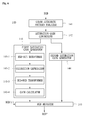
- Fig. 2 is a flow chart illustrating operation procedure of a white conversion portion of Fig. 1 .
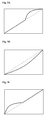
- Figs. 3A through 3C are graphs illustrating examples of tone mapping curves.
- image data including the primary RGB data signal is input to the histogram analyzer 120 and the RGB-RGBW transformation portion 130 (step S1).
- the histogram analyzer 120 analyzes the distribution of pixel data signals of the image data in accordance with brightness.
- the RGB-RGBW transformation portion 130 transforms the primary RGB data signals into the RGBW data signals (Step S3).
- the brightness reinforcement portion 150 can reinforce (or emphasize) the brightness of the W data signal by performing steps S4 through S6. More specifically, the brightness reinforcement portion 150 can determine based on the analyzed information, which includes the distribution of the pixel data signals, whether the image data corresponds to any one of low, middle and high brightness histograms (Step S4).
- the brightness reinforcement portion 150 can select any one of tone mapping curves on the basis of the determined histogram (Step S5). Finally, the brightness reinforcement portion 150 can adjust the brightness of the W data signal, which is applied from the RGB-RGBW transformation portion 130, according to the selected tone mapping curve (Step S6).
- the low brightness histogram means that the number of pixel data signals having dark (or low) brightness has the highest value in the input image data. In other words, the low brightness histogram represents that the number of pixel data signals having brightness close to the lowest gray scale level (for example, "0") becomes the highest value in the image data.
- the high brightness histogram means that the number of pixel data signals having bright (or high) brightness has the highest value in the input image data. In other words, the high brightness histogram represents that the number of pixel data signals having brightness close to the highest gray scale level (for example, "255") becomes the highest value in the image data.
- the middle brightness histogram means that the number of pixel data signals having middle brightness is the highest value in the input image data. In other words, the middle brightness histogram represents that the number of pixel data signals having brightness of the middle gray scale level range is the highest value in the input image data.
- the step S5 can include sub-steps S5-1 through S5-3.
- a tone mapping curve as shown in Fig. 3A can be selected (Sub-step S5-1).
- the low brightness of the input image data can be reinforced through the step S6.
- the contrast range (or contrast ratio) of the input image data can be enhanced.
- another tone mapping curve as shown in Fig. 3B can be selected (Sub-step S5-2) when it is determined in the step S4 that the input image data has the middle brightness histogram. As such, the middle brightness of the input image data can be reinforced through the step S6.
- the contrast range of the input image data can be enhanced.
- still another tone mapping curve as shown in Fig. 3C can be selected (Sub-step S5-3) when it is determined in the step S4 that the input image data has the high brightness histogram.
- the high brightness of the input image data can be reinforced through the step S6.
- the contrast range of the input image data can be enhanced.
- the tone mapping curves shown in Figs. 3A through 3C are used for adjusting the brightness range (or ratio), but the present disclosure is not limited to this. In other words, a variety of tone mapping curves can be used according to degree or width of adjustment of contrast range (or ratio).
- the brightness reinforcement portion 150 adjusts the brightness of the W data signal, which is output from the RGB-RGBW transformation portion 130, according to the selected tone mapping curve. As such, the contrast range (or ratio) of the input image data can be adjusted (or enhanced).
- Fig. 4 is a detailed block diagram showing an example of the brightness reinforcement portion in Fig. 1 .
- the brightness reinforcement portion 150 can include a brightness distribution determiner 151, a tone mapping curve generator 152 and a brightness adjuster 153.
- the brightness distribution determiner 151 can determine a degree of brightness, at which the largest number of color pixel data signals are positioned, on the basis of the analyzed information applied from the histogram analyzer 120.
- the brightness can be defined into n degrees.
- the "n" is an integer of at least 2.
- the distribution of color pixel data signals can be distinguished into n pixel data groups. If the "n" is 3, the color pixel data signals can be grouped into first through third pixel data groups.
- the first pixel data group includes the color pixel data signals positioned in a first brightness level (or value) range
- the second pixel data group includes the color pixel data signals positioned in a second brightness level range
- the third pixel data group includes the color pixel data signals positioned in a third brightness level range.
- the first through third brightness level ranges can be established by dividing a full brightness level range of 0 through 255 without overlapping with one another.
- the color pixel data signals included in the input image data can be divided (or grouped) into the first pixel data group having the first brightness level range of 0 ⁇ a first gray scale level, the second pixel data group having the second brightness level range, which is more than the first brightness level but less than a second brightness level, and the third pixel data group having the third brightness level range of the second brightness level ⁇ 255.
- the brightness distribution determiner 151 can determine whether a maximum pixel data group including a greatest number of color pixel data signals corresponds to anyone of the first through third pixel data groups.
- the first gray scale level is more than "0" but less than the second gray scale level
- the second gray scale level is less than "255".
- the tone mapping curve generator 152 can generate a tone mapping curve in accordance with the determined resultant of the brightness distribution determiner 151.
- the tone mapping curve generated in the tone mapping curve generator 152 can be used to adjust the brightnesses of the color pixel data signals (i.e., W sub-pixel data signals) which have the brightness levels corresponding to the maximum pixel data group.
- the Brightness reinforcement portion 150 can include a memory 154.
- the memory 154 can store a variety of tone mapping curves which includes three mapping curves shown in Figs. 3A through 3C .
- the tone mapping curve generator 152 can read the memory 154 and select anyone of the stored tone mapping curves.
- the tone mapping curve generator 152 can read-out a tone mapping curve, which corresponds to the determined resultant of the brightness distribution determiner 151, from the memory 154.
- the brightness adjuster 153 can adjust the brightness of the W data signal (i.e., the W sub-pixel data signals) on the basis of the tone mapping curve which is generated in (or selected by) the tone mapping curve generator 152. Also, the brightness adjuster 153 can output an adjusted W data signal (or adjusted W sub-pixel data signals). In this manner, the generated or selected tone mapping curve can change along degrees of the brightness of the input image data, i.e. the distribution of color pixel data signals in accordance with low, middle and high brightness level ranges. As such, an image with a high contrast range (or ratio) can be realized by the adjusted W data signal (or the adjusted W sub-pixel data signals).
- the data conversion unit 100 can be applied to an LCD device.
- the LCD device can adjust the contrast range of the W data signal corresponding to a brightness component.
- the LCD device can display an image of a high contrast ratio without increasing the luminosity of a backlight.
- the LCD device can reduce power consumption.
- Fig. 5 is a flowchart illustrating an operation procedure of the RGB reinforcement portion shown in Fig. 1 .
- the RGB reinforcement portion 140 analyzes a color attribute pattern for each color pixel data signal of the input image data using the primary RGB data signals.
- the analyzed resultant of the color attribute pattern for one color pixel data signal (hereinafter, "respective color pixel data signal') can be obtained by sequentially performing a color attribute analysis for the respective (corresponding) color pixel data signal and 8 color pixel data signals two-dimensionally adjacent thereto.
- the 8 color pixel data signals P (j-1)(k-1) , P j(k-1) , P (j+1)(k-1) , P (j-1)k , P (j+1)k , P (j-1)(k+1) , P j(k+1) and P (j+1)(k+1) adjacent to the respective color pixel data signal Pjk can be opposite to (j-1)(k-1), j(k-1), (j+1)(k-1), (j-1)k, (j+1)k, (j-1)(k+1), j(k+1) and (j+1)(k+1) color pixels.
- the RGB reinforcement portion 140 checks gray scale values of primary RGB sub-pixel data signals for the color pixel data signal and selects the largest sub-pixel data signal and the smallest sub-pixel data signal (Step S11). Also, the RGB reinforcement portion 140 multiplies the smallest sub-pixel data signal by a color attribution coefficient "a" and determines whether the multiplied value is larger or smaller than the largest sub-pixel data signal. If the multiplied value is smaller than the largest sub-pixel data signal, the RGB reinforcement portion 140 counts up a pixel number Xjk by "1" (Step S12).
- the RGB reinforcement portion 140 counts down (or decreases) the pixel number Xjk by "1" (Step S13).
- the RGB reinforcement portion 140 determines on the basis of the counted pixel number Xjk whether the respective color pixel data signal Pjk corresponds to anyone of chromatic or achromatic colors (Step S14). If the counted pixel number Xjk is larger than "0", the RGB reinforcement portion 140 determines that the respective color pixel data signal Pjk corresponds to the chromatic color.
- the RGB reinforcement portion 140 determines that the respective color pixel data signal Pjk corresponds to the achromatic color.
- the color attribution coefficient "a” is a previously set value.
- the color attribution coefficient "a” can be set to "1.5” but it is not limited to this. In other words, the color attribution coefficient "a” can be varied along conditions discriminating between the chromatic and achromatic colors.
- the RGB reinforcement portion 140 sets all the RGB gain values of the respective color pixel data signal to '1' (Step S 15).
- the RGB reinforcement portion 140 calculates variable RGB gain values in accordance with the gray scale values of the primary RGB sub-pixel data signals by performing steps S16 through S19.
- the RGB reinforcement portion 140 transforms the primary RGB sub-pixel data signals of the respective color pixel data signal into hue, intensity and saturation values (Step S16).
- the RGB reinforcement portion 140 multiplies the transformed saturation component by a saturation emphasis coefficient "b" (Step S17).
- the RGB reinforcement portion 140 inverse-transforms the hue value, the intensity value and the multiplied saturation value into R, G and B sub-pixel data signals RGB' (Step S18).
- the RGB reinforcement portion 140 sets the variable RGB gain values of the transformed RGB sub-pixel data signals RGB(t) by dividing each of the inverse-transformed R, G and B sub-pixel data signals by each of the primary R, G and B sub-pixel data signals (Step S19).
- the R gain value can be set to a ratio of "the inverse-transformed R sub-pixel data signal R' / the primary R sub-pixel data signal R”.
- the G gain value can be set to a ratio of "the inverse-transformed G sub-pixel data signal G'/ the primary G sub-pixel data signal G”.
- the B gain value can be set to a ratio of "the inverse-transformed B sub-pixel data signal B' / the primary B sub-pixel data signal B".
- the saturation emphasis coefficient "b” is a previously set value.
- the saturation emphasis coefficient "b” can be set to "1.1” but it is not limited to this.
- the saturation emphasis coefficient "b” can be varied along a degree of reinforcement of the saturation component.
- the RGB reinforcement portion 140 can reinforce the transformed R, G and B sub-pixel data signals RGB(t) using the gain values which are set in the step S15 or S 19 (Step S20).
- the reinforced R, G and B sub-pixel data signals RGB" are applied to the rendering portion 160.
- the RGB reinforcement portion 140 divides the color pixel data signals of the input image data into the chromatic and achromatic colors and performs the saturation reinforcement only for the color pixel data signals corresponding to the chromatic color. As such, the saturation of the image can be efficiently enhanced.
- Fig. 6 is a detailed block diagram showing an example of the RGB reinforcement portion in Fig. 1 .
- the RGB reinforcement portion 140 can include a color attribute pattern analyzer 141, a saturation gain controller 142, a first saturation gain generator 143, a second saturation gain generator 144 and a RGB adjuster 145.
- the first saturation gain generator 143 can include a RGB-to-HIS (hereinafter, 'RGB-HIS') transformer 143-1, a saturation emphasizer 143-2, a HIS-to-RGB (hereinafter, 'HIS-RGB') transformer 143-3 and a gain calculator 143-4.
- the color attribute pattern analyzer 141 analyzes a color attribute pattern for each color pixel data signal of the input image data using the primary RGB data signals. Also, the color attribute pattern analyzer 141 applies an analyzed resultant of the color attribute pattern for each color pixel data signal to the saturation gain controller 142.
- the analyzed resultant of the color attribute pattern for one color pixel data signal (hereinafter, “respective color pixel data signal”) can be obtained by sequentially performing a color attribute analysis for the respective (corresponding) color pixel data signal and 8 color pixel data signals two-dimensionally adjacent thereto.
- the 8 color pixel data signals P (j-1)(k-1), Pj(k-1), P (j+1)(k-1) , P (j-1)k , P (j+1)k , P (j-1)(k+1) , P j(k+1) and P (j+1)(k+1) adjacent to the respective color pixel data signal Pjk can be opposite to ((j-1)(k-1))th, (j(k-1))th, ((j+1)(k-1))th, ((j-1)k)th, ((j+1)k)th, ((j-1)(k+1))th, (j(k+1))th and ((j+1)(k+1))th color pixels.
- the color attribute pattern analyzer 141 checks gray scale values of primary RGB sub-pixel data signals for the color pixel data signal and selects the largest sub-pixel data signal and the smallest sub-pixel data signal. Also, the color attribute pattern analyzer 141 multiplies the smallest sub-pixel data signal by a color attribution coefficient "a" and determines whether the multiplied value is larger or smaller than the largest sub-pixel data signal. If the multiplied value is smaller than the largest sub-pixel data signal, the color attribute pattern analyzer 141 counts up a pixel number Xjk by "1".
- the color attribute pattern analyzer 141 counts down (or decreases) the pixel number Xjk by "1".
- the color attribute pattern analyzer 141 supplies the saturation gain controller 142 with the counted pixel number Xjk which is used as an analyzed resultant of the color attribute pattern for one color pixel data signal.
- the saturation gain controller 142 determines on the basis of the counted pixel number Xjk, which is applied from the color attribute pattern analyzer 141, whether the respective color pixel data signal Pjk corresponds to anyone of chromatic or achromatic colors. If the counted pixel number Xjk is larger than "0" (i.e., a positive number), the saturation gain controller 142 determines that the respective color pixel data signal Pjk corresponds to the chromatic color. On the contrary, when the counted pixel number Xjk is smaller than "0" (i.e., a negative number), the saturation gain controller 142 determines that the respective color pixel data signal Pjk corresponds to the achromatic color.
- the saturation gain controller 142 can drive the first saturation gain generator 143. On the contrary, when the respective color pixel data signal Pjk corresponds to the achromatic color, the saturation gain controller 142 can drive the second saturation gain generator 144.
- the first saturation gain generator 143 can be selectively driven by the saturation gain controller 142. Such a first saturation gain generator 143 can generate variable gain values of the transformed RGB data signals according to the primary RGB data signals.
- the RGB-HIS transformer 143-1 transforms the primary RGB sub-pixel data signals Rjk, Gjk and Bjk of the respective color pixel data signal Pjk into hue, intensity and saturation values.
- the saturation emphasizer 143-2 can emphasize the transformed saturation value, which is applied from the RGB-HIS transformer 143-1, by multiplying the transformed saturation value by a previously set saturation emphasis coefficient 'b'.
- the HIS-RGB transformer 143-3 inverse-transforms the hue and intensity values from the RGB-HIS transformer 143-1 and the emphasized saturation value (or the multiplied value) from the saturation emphasizer 143-3 into RGB sub-pixel data signals Rjk', Gjk' and Bjk'.
- the gain calculator 143-4 divides each of the inverse-transformed RGB sub-pixel data signals Rjk', Gjk' and Bjk', which are applied from the HIS-RGB transformer 143-3, by each of the primary RGB sub-pixel data signals Rjk, Gjk and Bjk.
- the gain calculator 143-4 can obtains an R gain value Gain Rjk of "Rjk'/Rjk", a G gain value Gain Gjk of "Gjk'/Gjk” and a B gain value Gain Bjk of "Bjk'/Bjk” with respect to the respective color pixel data signal Pjk.
- the second saturation gain generator 144 can be selectively driven by the saturation gain controller 142.
- the second saturation gain generator 144 can generate fixed R, G and B gain values Gain R , Gain G and Gain B which are previously set to a constant value regardless of the color pixel data signals. All the fixed R, G and B gain values can be set to "1", but the present disclosure is not limited to this.
- the RGB adjuster 145 can reinforce the transformed RGB data signals RGB(t) of the input image data using either the variable RGB gain values, which are applied from the gain calculator 143-4 of the first saturation gain generator 143, or the fixed RGB gain values which are applied from the second saturation gain generator 144.
- the RGB adjuster 145 adjusts (or reinforces) the transformed RGB sub-pixel data signals RGB(t) for each color pixel data signal using the variable RGB gain values which are varied along the color pixel data signals and applied from the gain calculator 143-4.
- the RGB adjuster 145 adjusts (or reinforces) the transformed RGB sub-pixel data signals RGB(t) for each color pixel data signal using the fixed RGB gain values which are applied from the second saturation gain generator 144, when the second saturation gain generator 144 is driven instead of the first saturation gain generator 143.
- the RGB adjuster 145 either increases the gray scale values of the transformed RGB sub-pixel data signals RGB(t) or outputs the transformed RGB sub-pixel data signals RGB(t) as they are, on the basis of the analyzed color attribute pattern. As such, only the transformed RGB data signals corresponding to the chromatic color can be reinforced with the exception of the transformed RGB data signals RGB(t) corresponding to the achromatic color.
- the RGB reinforcement portion 140 can perform the saturation reinforcement only for the chromatic color pixel data signal with the exception of the achromatic color pixel data signals.
- the reinforced RGB data signals RGB" are applied from the RGB adjuster 145 of the RGB reinforcement portion 140 to the rendering portion 160 shown in Fig. 1 .
- the data conversion unit 100 and method according to embodiments of the present disclosure can adjust the contrast ratio of the input image data by independently controlling the W data signal. As such, complex operations can be simplified and memory capacity can be reduced.
- the data conversion unit 100 and method according to embodiments of the present disclosure can analyze the brightness distribution of the color pixel data signals of the input image data, select or generate the tone mapping curve in accordance with the analyzed brightness distribution, and applies the selected or generated tone mapping curve to the W data signal. Therefore, a high contrast ratio can be realized.
- the data conversion unit 100 and method can analyze the color attribute pattern of each color pixel data signal of the input image data, set different emphasis ratios to the color pixel data signals of the input image data, and reinforce the color pixel data signals using the different emphasis ratios. In accordance with, the deterioration of the saturation of the input image data can be prevented, and furthermore image quality can be enhanced.
- the data conversion unit 100 can be applied an LCD device for adjusting the brightness of the W data signal without increasing the luminosity of the backlight. As such, difficulty in increasing brightness due to transmittance of a liquid crystal material can be solved. Also, the LCD device with the data conversion unit 100 can display a high brightness image.
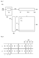
- Fig. 7 is a block diagram showing a display device with a data conversion unit according to an embodiment of the present disclosure.
- Fig. 8 is a planar view showing arrangement of sub-pixels.
- the display device can include a display panel 200, a data driver 300, a gate driver 400 and a timing controller 500.
- the timing controller 500 can include a data conversion unit 100.
- the data conversion unit 100 can be included in the display device in such a manner as to be separate from the timing controller 500.
- the data conversion unit 100 can be built into the timing controller 500, or separated from the timing controller 500. Although it is explained that the data conversion unit 100 is applied to the display device 600, it is not limited to this. Alternatively, the data conversion unit 100 can be applied to wireless communication devices such as mobile wireless handsets, display modules of digital and video cameras, digital multimedia players, personal digital assistants (PDAs), video game consoles, video display devices and exclusive viewing stations such as television receivers.
- wireless communication devices such as mobile wireless handsets, display modules of digital and video cameras, digital multimedia players, personal digital assistants (PDAs), video game consoles, video display devices and exclusive viewing stations such as television receivers.
- the display panel 200 includes a plurality of gate lines GL1 ⁇ GLn and a plurality of data lines DL1 ⁇ DLm. Also, the display panel 200 includes sub-pixels Pix formed in respective regions which is defined by the pluralities of gate lines GL1 ⁇ GLn and data lines DL1 ⁇ DLm.
- the gate driver 400 replies to gate control signals GCS applied from the timing controller 500, and supplies a plurality of scan signals SP to the plurality of gate lines GL1 ⁇ GLn, respectively.
- the plurality of scan signals SP can sequentially enable the plurality of gate lines GL1 ⁇ GLn in one horizontal synchronous signal interval.
- Such a gate driver 400 can be configured with a plurality of gate IC (Integrated circuit) chips.
- the data driver 300 can reply to data control signals DCS applied from the timing controller 500 and generate data voltages whenever anyone among the plurality of gate lines GL1 ⁇ GLn is enabled.
- the data voltages generated in the data driver 300 are applied to the plurality of data lines DL1 ⁇ DLm on the display panel 200.
- the timing controller 500 can generate the gate control signals GCS and the data control signals DCS using a various control signals which are applied from an external system (not shown) such as a graphic module of a computer system or an image demodulation module of a television receiver.
- the gate control signals GCS are used to control the gate driver 400 and the data control signals DCS are used to control the data driver 300.
- the sub-pixels Pix on the display panel 200 can be used to display R, G, B and W colors.
- the color sub-pixels can be arranged as shown in Fig. 8 .
- the color sub-pixels can be repeatedly arranged on an odd-numbered horizontal line k in order of a W sub-pixel 101, an R sub-pixel 102, a G sub-pixel 103 and a B sub-pixel 104.
- the color sub-pixels can be repeatedly arranged on an even-numbered horizontal line k+1 in order of a G sub-pixel 103, a B sub-pixel 104, a W sub-pixel 101 and an R sub-pixel 102.
- the color sub-pixels on the odd-numbered horizontal line k and the respective (or same) color sub-pixels on the even-numbered horizontal line k+1 can be arranged along a vertical direction in a zigzag pattern not a line (or row).
- two W sub-pixels 101 can be positioned at an intersection of a jth vertical line and the odd-numbered horizontal line k and another intersection of a (j+1)th vertical line and the even-numbered horizontal line k+1.
- one of two same color sub-pixels i.e., two R, G, B or W sub-pixels
- an arbitrary vertical line for example, jth vertical line
- the other one is disposed on a different vertical line (for example, (j-2 or J+2)th vertical line) which is shifted from the arbitrary vertical line by two sub-pixels in a lateral direction.
- Such zigzaged sub-pixel arrangement which allows same color sub-pixels on the odd-numbered line k and the even-numbered horizontal line k+1 to be shifted from each other by the distance (or length) of two sub-pixels, can prevent the appearance of straight lines unless linear sub-pixel arrangement allowing same color sub-pixels to be arranged in a vertical direction.
- the sub-pixel Pix includes a thin film transistor TFT connected to one of the gate lines GL1 ⁇ GLn and one of the data lines DL1 ⁇ DLm and a pixel electrode connected to the thin film transistor.
- the thin film transistor TFT transfers a data voltage on one of the data lines DL1 ⁇ DLm to a liquid crystal cell (or the pixel electrode) in response to a scan signal SP from one of the gate lines GL1 ⁇ GLn.
- the thin film transistor TFT includes a gate electrode connected to one of the gate lines GL1 ⁇ GLn, a source electrode connected to one of the data lines DL1 ⁇ DLm, and a drain electrode connected to the pixel electrode of the liquid crystal cell.
- a storage capacitor for maintaining the voltage of the liquid crystal cell is formed on a lower glass substrate of the display panel 200.
- color filters and a black matrix can be formed on an upper glass substrate of the display panel 200. The color filter is formed opposite to a pixel region in which the thin film transistor TFT is formed. The black matrix rims the color filters and shields the gate lines GL1 ⁇ GLN, the data lines DL1 ⁇ DLm, the thin film transistor and so one.
- Such color filters allow the sub-pixels to be distinguished in R, G, B and W sub-pixels.
- the liquid crystal cells included in the R, G, B and W sub-pixels can be used to display R, G, B and W colors, respectively.
- an organic light emitting diode display panel can be used.
- the R, G, B and W sub-pixels can each include an organic light emitting diode.
- Such R, G, B and W sub-pixels can output respective color lights by emitting the respective organic light emitting diodes.
- the organic light emitting diode display panel can display an image.
- the organic light emitting diode can be formed in either a structure including a hole transport layer, an organic emission layer and an electron transport layer or another structure including a hole injection layer, a hole transport layer, an organic emission layer, an electron transport layer and an electron injection layer.
- a functional layer for enhancing light emission efficiency and life span of the organic emission layer can be additionally included in the organic light emitting diode.
Landscapes
- Engineering & Computer Science (AREA)
- Multimedia (AREA)
- Signal Processing (AREA)
- Physics & Mathematics (AREA)
- General Physics & Mathematics (AREA)
- Theoretical Computer Science (AREA)
- Computer Hardware Design (AREA)
- Color Image Communication Systems (AREA)
- Image Processing (AREA)
- Facsimile Image Signal Circuits (AREA)
- Processing Of Color Television Signals (AREA)
- Control Of Indicators Other Than Cathode Ray Tubes (AREA)
Abstract
Description
- The present application claims priority under 35 U.S.C. § 119(a) of
Korean Patent Application No. 10-2014-0144503 filed on October 23, 2014 - The present application relates to data conversion unit and method for converting image data and a display device having a data conversion unit.
- Display devices can display various types of image data which are captured by a still photo or digital video camera, obtained from a still photo archive, generated through software application, or received through one of broadcast or streaming medium. The display devices can be integrated with a variety of electrical appliances. For example, the display devices can be integrated with desktop computers, laptop computers, computer workstations, personal digital assistants, mobile device such as mobile phones, wireless communication devices, multimedia devices, exclusive viewing stations such as cameras and television receivers. Also, the display devices can be combined with the other electrical appliances. In other words, the display devices can be applied to a variety of electrical appliances. Such display devices can include liquid crystal display (LCD) devices, cathode ray tube (CRT) display devices, plasma display devices, projection display devices, organic light emitting diode display devices and so on.
- Recently, the display devices are being developed to realize high image quality and reduce power consumption through increment of brightness. Meanwhile, the display device not only displays a color image using three primary colors including red, green and blue colors but also realizes peak brightness using the red, green and blue colors. In other words, the white color must depend on the red, green and blue colors. As such, it is difficult for desired brightness of the white color to control brightness of the red, green and blue colors. Particularly, it is more difficult for the LCD display device to increase brightness due to transmittance of liquid crystal.
- Moreover, a multi-frame HDR (high dynamic range) imaging technology is employed for realize the high dynamic range. However, the multi-frame HDR imaging technology must require complex operations. Due to this, the multi-frame HDR imaging technology must increase memory capacity and cost thereof.
- Accordingly, embodiments of the present application are directed to data conversion unit and method for conversion of data and a display device that substantially obviate one or more of problems due to the limitations and disadvantages of the related art.
- The embodiments relate to provide data conversion unit and method and a display device which are adapted to increase brightness by adding white pixel data.
- Also, the embodiments relate to provide data conversion unit, a method and a display device which are adapted to independently control brightness of white data signal.
- Moreover, the embodiments relate to provide data conversion unit, method and a display device which are adapted to realize a high contrast ratio without increasing brightness of backlight.
- Additional features and advantages of the embodiments will be set forth in the description which follows, and in part will be apparent from the description, or may be learned by practice of the embodiments. The advantages of the embodiments will be realized and attained by the structure particularly pointed out in the written description and claims hereof as well as the appended drawings.
- A data conversion unit according to an aspect of the present embodiment can include: a transformation portion configured to transform R (red), G (green) and B (blue) sub-pixel data signals of input image data into R, G, B and W (white) sub-pixel data signals; and a brightness reinforcement portion configured to reinforce brightness of the transformed W sub-pixel data signal based on distribution of color pixel data signals of the input image data in accordance with brightness.
- The data conversion unit according to an aspect of the present embodiment can further include a RGB reinforcement portion configured to selectively perform saturation reinforcement for the transformed RGB sub-pixel data signals according to a color attribute pattern of each color pixel data signal of the input image data.
- In the data conversion unit according to an aspect of the present embodiment, the brightness reinforcement portion can include: a brightness distribution determiner configured to determine the distribution of the color pixel data signals of the input image data in accordance with the brightness using the RGB sub-pixel data signals of the input image data; a tone mapping curve generator configured to generate a tone mapping curve in accordance with the determined resultant of the brightness distribution determiner; and a brightness adjuster configured to adjust the brightness of the W sub-pixel data signal on the basis of the tone mapping curve generated in the tone mapping curve generator.
- In the data conversion unit according to an aspect of the present embodiment, the brightness distribution determiner can divide the color pixel data signals of the input image date into first through nth color pixel data signal groups, which are opposite to first through nth gray scale level ranges, according to their brightness using a brightness distribution of pixel data signals of the input image data, and determine whether anyone of the first through nth color pixel data signal groups corresponds to a maximum pixel data signal group including a largest number of color pixel data signals. The "n" can be a natural number of at least 2.
- The data conversion unit according to an aspect of the present embodiment can allow the brightness of the gray scale level range opposite to the maximum pixel data signal group is adjusted by the generated tone mapping curve.
- The RGB reinforcement portion included in the data conversion unit according to an aspect of the present embodiment can include: a color attribute pattern analyzer configured to analyze the color attribute pattern for each of color pixel data signals of the input image data; a saturation gain generator configured to selectively generate different saturation gain values according to the analyzed resultant of the color attribute pattern analyzer; and a RGB adjuster configured to adjust the RGB sub-pixel data signals using the selectively generated saturation gain value.
- In the data conversion unit according to an aspect of the present embodiment, the saturation gain generator can include: a first saturation gain generator selectively driven according to the analyzed resultant of the color attribute pattern analyzer and configured to generate a variable saturation gain value; and a second saturation gain generator driven alternately with the first saturation gain generator according to the analyzed resultant of the color attribute pattern analyzer and configured to generate a fixed saturation gain value.
- The data conversion unit according to an aspect of the present embodiment can allow the first saturation gain generator to be driven when it is determined on the basis of the analyzed resultant of the color attribute pattern analyzer that the color pixel data signal corresponds to a chromatic color. Also, the data conversion unit can enable the second saturation gain generator to be driven when it is determined on the basis of the analyzed resultant of the color attribute pattern analyzer that the color pixel data signal corresponds to an achromatic color.
- The data conversion unit according to an aspect of the present embodiment can allow the variable saturation gain value to be varied along gray scale values of the RGB sub-pixel data signals of the input image data.
- The data conversion unit according to an aspect of the present embodiment can further include a de-gamma portion configured to perform a de-gamma treatment for the RGB sub-pixel data signals of the image data which are applied to the RGB-RGBW transformation portion.
- The data conversion unit according to an aspect of the present embodiment can include a rending portion configured to a rending treatment for the brightness-reinforced W sub-pixel data signal, which is applied from the brightness reinforcement portion, and the saturation-reinforced RGB sub-pixel data signals applied from the RGB reinforcement portion.
- A data conversion method according to another aspect of the present embodiment can include: transforming R (red), G (green) and B (blue) sub-pixel data signals of input image data into R, G, B and W (white) sub-pixel data signals; analyzing the number of color pixel data signals, which each include the RGB sub-pixel data signals, in accordance with brightness on the basis of the RGB sub-pixel data signals of the input image data and generating a histogram; and reinforcing brightness of the transformed W sub-pixel data signal based on the histogram.
- Preferably, the data conversion method further comprises: dividing the color pixel data signals of the input image date into first through nth color pixel data signal groups, which are opposite to first through nth gray scale level ranges, according to their brightness on the basis of the histogram; detecting a maximum color pixel data signal group, which includes a largest number of color pixel data signals, among the first through nth color pixel data signal groups; setting a tone mapping curve which is used to adjust brightness of the gray scale level range opposite to the maximum color pixel data signal group; and adjusting the brightness of the W sub-pixel data signal according to the set tone mapping curve, wherein "n" is a natural number of at least 2.
- The data conversion method according to an aspect of the present embodiment can further include: analyzing a color attribute pattern for each of color pixel data signals of the input image data; setting one of different saturation gain values according to the analyzed color attribute pattern; and performing a saturation adjustment for the transformed RGB sub-pixel data signals using the set saturation gain value.
- The data conversion method according to an aspect of the present embodiment can allow the different saturation gain values to include a variable saturation gain value and a fixed saturation gain value.
- In the data conversion method according to an aspect of the present embodiment, the variable saturation gain value can be varied along gray scale values of the RGB sub-pixel data signals of the input image data.
- The data conversion method according to an aspect of the present embodiment can allow the variable saturation gain value to be set when it is determined on the basis of the analyzed color attribute pattern that the color pixel data signal corresponds to a chromatic color. Also, the data conversion method can enable the fixed saturation gain value to be set when it is determined on the basis of the analyzed color attribute pattern that the color pixel data signal corresponds to an achromatic color.
- Further the object is solved by a display device comprising a display panel, a data driver, a gate driver and a data conversion unit is described above.
- Other systems, methods, features and advantages will be, or will become, apparent to one with skill in the art upon examination of the following figures and detailed description. It is intended that all such additional systems, methods, features and advantages be included within this description, be within the scope of the present disclosure, and be protected by the following claims. Nothing in this section should be taken as a limitation on those claims. Further aspects and advantages are discussed below in conjunction with the embodiments. It is to be understood that both the foregoing general description and the following detailed description of the present disclosure are exemplary and explanatory and are intended to provide further explanation of the disclosure as claimed.
- The accompanying drawings, which are included to provide a further understanding of the embodiments and are incorporated herein and constitute a part of this application, illustrate embodiment(s) of the present disclosure and together with the description serve to explain the disclosure. In the drawings:
-
Fig. 1 is a block diagram showing a data conversion unit according to an embodiment of the present disclosure; -
Fig. 2 is a flow chart illustrating an operation procedure of a brightness reinforcement portion inFig. 1 ; -
Figs. 3A through 3C are graphs illustrating examples of tone mapping curves; -
Fig. 4 is a detailed block diagram showing a brightness reinforcement portion ofFig. 1 ; -
Fig. 5 is a flowchart illustrating an operation procedure of the RGB reinforcement portion inFig. 1 ; -
Fig. 6 is a detailed block diagram showing an example of the RGB reinforcement portion inFig. 1 -
Fig. 7 is a block diagram showing a display device which includes a data conversion unit in accordance with an embodiment of the present disclosure; and -
Fig. 8 is a planar view showing arrangement of sub-pixels. - Reference will now be made in detail to an OLED display device in accordance with the embodiments of the present disclosure, examples of which are illustrated in the accompanying drawings. These embodiments introduced hereinafter are provided as examples in order to convey the idea to the ordinary skilled person in the art. Therefore, these embodiments might be embodied in a different shape, so are not limited to these embodiments described here. In the drawings, the size, thickness and so on of a device can be exaggerated for convenience of explanation. Wherever possible, the same reference numbers will be used throughout this disclosure including the drawings to refer to the same or like parts.
- For the convenience of explanation, some terms being used in the present disclosure can be defined as follows.
- "Color pixel data signal" includes R (red), G (green) and B (blue) sub-pixel data signals. "Image data" includes color pixel data signals which are continuously arranged in a row or a line. In detail, "image data" includes R, G and B sub-pixel data signals which are arranged repeatedly and alternately with one another. Also, "RGB data signals" mean that R, G and B sub-pixel data signals are arranged repeatedly and alternately with one another. Similarly, "RGBW data signals" represent the R, G, B and W sub-pixel data signals are arranged repeatedly and alternately with one another.
-
Fig. 1 is a block diagram showing a data conversion unit according to an embodiment of the present disclosure. - A
data conversion unit 100 according to an embodiment of the present disclosure, which is shown inFig. 1 , can receive red (hereinafter, "R"), green (hereinafter, "G") and blue (hereinafter, "B") data signals, convert the R, G and B data signals into R, G, B and white (hereinafter, "W") data signals. Also, thedata conversion unit 100 can reinforce saturations of the R, G and B data signals and brightness of the W data signal and output the reinforced R, G, B and W data signals. To this end, thedata conversion unit 100 can include ade-gamma portion 110, ahistogram analyzer 120, a RGB to RGBW (hereinafter, "RGB-RGBW")transformation portion 130, aRGB reinforcement portion 140, abrightness reinforcement portion 150 and arendering portion 160, as shown inFig. 1 . - The
de-gamma portion 110 can receive RGB data signals for images and perform a de-gamma treatment for the input RGB data signals in a frame unit. Also, thede-gamma portion 110 can perform a bit-stretch treatment for the de-gamma-treated RGB data signals. More specifically, thede-gamma portion 110 compensates for gamma errors, which would result in display errors on a display panel, through the de-gamma treatment. As such, the de-gamma-treated RGB signals allows the display panel to have a linear optical property. Also, thede-gamma portion 110 can increase the de-gamma-treated RGB data signals in the number of bits through the bit stretch treatment. In accordance therewith, the generation of bit overflow phenomena at data operations, which are performed for converting the RGB data signals into the RGBW data signals, can be prevented. Such ade-gamma portion 110 can simultaneously perform the de-gamma treatment and the bit stretch treatment using a de-gamma LUT (look-up-table). - The
histogram analyzer 120 receives the de-gamma-treated RGB data signals from thede-gamma portion 110. Also, thehistogram analyzer 120 can analyze information involved in the de-gamma-treated RGB data signals. The analyzed information obtained from the RGB data signals is necessary to reinforce brightness of the W data signal. Such analyzed information can be realized as a histogram which includes contrast differences between bright and dark patterns (or sites) within the respective image, a distribution of brightness values within the respective image or others. In detail, the histogram can be defined as an aggregate which includes the number of pixels for each brightness value within a single image. Actually, the histogram can provide pixel distributions for gray scale levels of 0-255 within a single image. Such ahistogram analyzer 120 can analyze distributions of pixels within a single image in accordance with brightness on the basis of the input RGB data signals. Moreover, thehistogram analyzer 120 can provide histograms (i.e., RGB histograms) for each of the RGB components based on the received RGB data signals. - The RGB-
RGBW transformation portion 130 converts the RGB data signals, which are may be supplied from thede-gamma portion 110 into RGBW data signals. However thede-gamma portion 110 is optional. The RGBW data signals obtained by the RGB-RGBW transformation portion 130 are used to drive a display panel including RGBW sub-pixels. In order to optimize power consumption without changing color coordinates, the RGB-RGBW transformation portion 130 can add a W data signal using RGB data components, which are based on measured or estimated values having the same brightness and color coordinate as a W data component, and perform subtractions of the RGB data components from the (de-gamma)-treated RGB data signals. For example, the RGB-RGBW transformation portion 130 can generate the W data signal by extracting one of a common gray scale value, which is represented byequation 1, and a minimum gray scale value, which is represented byequation 2, from the (de-gamma)-treated RGB data signal. Also, the RGB-RGBW transformation portion 130 can generate secondary RGB data signals by subtracting the W data signal from each of the (de-gamma)-treated RGB data signals.

- In another different manner, the RGB-
RGBW transformation portion 130 can convert R, G and B data signals into four color data signal, which include R, G, B and W data signals, using data conversion methods which are based on properties of each sub-pixel such as a brightness property of the sub-pixel and a driving property of the sub-pixel. In this case, the RGB-RGBW transformation portion 130 can convert the RGB data signals into the RGBW data signals using data conversion methods. - For the convenience of explanation, the (de-gamma)-treated RGB data signals being input to the RGB-
RGBW transformation portion 130 will be referred to as "primary RGB data signals" and the RGB data signals of the RGBW data signals being output from the RGB-RGBW transformation portion 130 will be referred to as "transformed RGB data signals". - The
RGB reinforcement portion 140 receives the primary RGB data signals from thede-gamma portion 110 and analyzes saturation components of the primary RGB signals. Also, theRGB reinforcement portion 140 receives the transformed RGB data signals RGB(t) of the RGBW data signals, which are generated in the RGB-RGBW transformation portion 130, and reinforce the saturation of the transformed RGB data signals RGB(t) among the RGBW data signals on the basis of the analyzed saturation components. The saturation means a hue quantity in an arbitrary color or a color purity which is varied along the progression from a white color to a gray color. As such, the saturation of a color can become higher as the color is close to a light spectrum which is mixed with any one of white and black colors. TheRGB reinforcement portion 140 can distinguish on the basis of the primary RGB data signals whether an image is close to an achromatic color or a chromatic color. If the image is close to the achromatic color, theRGB reinforcement portion 140 can reinforce the saturations of the transformed RGB data signals RGB(t). The achromatic color means a color which includes only intensity without any hue and saturation, and the chromatic color means every color with the exception of the achromatic colors. In order to reinforce the saturations of the transformed RGB data signals, theRGB reinforcement portion 140 can transform the primary RGB data signals into a HIS (hue-intensity-saturation) color model. Also, theRGB reinforcement portion 140 can differently reinforce the saturations of the transformed RGB data signals RGB(t) on the basis of the HIS color model. Such a HIS color model is based on (or derived from) the human color perception model. As such, the HIS color model allows hue, saturation and intensity to be distinguished. - The
brightness reinforcement portion 150 receives the W data signal among the RGBW data signals which are generated in the RGB-RGBW transformation portion 130. Also, thebrightness reinforcement portion 150 can reinforce the brightness of the W data signal on the basis of the analyzed histogram which is applied from thehistogram analyzer 120. - The rending
portion 160 can combine the reinforced RGB data signals, which are applied from theRGB reinforcement portion 140, with the reinforced W data signal which is applied from thebrightness reinforcement portion 150. As such, reinforced RGBW data signals can be output from therendering portion 160. Also, therendering portion 160 can correct contour, color, shadow, position and so on, in order to enhance reality of an image. -
Fig. 2 is a flow chart illustrating operation procedure of a white conversion portion ofFig. 1 .Figs. 3A through 3C are graphs illustrating examples of tone mapping curves. - Referring to
Fig. 2 , image data including the primary RGB data signal is input to thehistogram analyzer 120 and the RGB-RGBW transformation portion 130 (step S1). In step S2, thehistogram analyzer 120 analyzes the distribution of pixel data signals of the image data in accordance with brightness. Meanwhile, the RGB-RGBW transformation portion 130 transforms the primary RGB data signals into the RGBW data signals (Step S3). Thebrightness reinforcement portion 150 can reinforce (or emphasize) the brightness of the W data signal by performing steps S4 through S6. More specifically, thebrightness reinforcement portion 150 can determine based on the analyzed information, which includes the distribution of the pixel data signals, whether the image data corresponds to any one of low, middle and high brightness histograms (Step S4). Subsequently, thebrightness reinforcement portion 150 can select any one of tone mapping curves on the basis of the determined histogram (Step S5). Finally, thebrightness reinforcement portion 150 can adjust the brightness of the W data signal, which is applied from the RGB-RGBW transformation portion 130, according to the selected tone mapping curve (Step S6). - The low brightness histogram means that the number of pixel data signals having dark (or low) brightness has the highest value in the input image data. In other words, the low brightness histogram represents that the number of pixel data signals having brightness close to the lowest gray scale level (for example, "0") becomes the highest value in the image data. The high brightness histogram means that the number of pixel data signals having bright (or high) brightness has the highest value in the input image data. In other words, the high brightness histogram represents that the number of pixel data signals having brightness close to the highest gray scale level (for example, "255") becomes the highest value in the image data. The middle brightness histogram means that the number of pixel data signals having middle brightness is the highest value in the input image data. In other words, the middle brightness histogram represents that the number of pixel data signals having brightness of the middle gray scale level range is the highest value in the input image data.
- The step S5 can include sub-steps S5-1 through S5-3. In detail, if it is determined in the step S4 that the input image data corresponds to the low brightness histogram, a tone mapping curve as shown in
Fig. 3A can be selected (Sub-step S5-1). In this case, the low brightness of the input image data can be reinforced through the step S6. As such, the contrast range (or contrast ratio) of the input image data can be enhanced. Also, another tone mapping curve as shown inFig. 3B can be selected (Sub-step S5-2) when it is determined in the step S4 that the input image data has the middle brightness histogram. As such, the middle brightness of the input image data can be reinforced through the step S6. In accordance therewith, the contrast range of the input image data can be enhanced. Moreover, still another tone mapping curve as shown inFig. 3C can be selected (Sub-step S5-3) when it is determined in the step S4 that the input image data has the high brightness histogram. As such, the high brightness of the input image data can be reinforced through the step S6. In accordance therewith, the contrast range of the input image data can be enhanced. The tone mapping curves shown inFigs. 3A through 3C are used for adjusting the brightness range (or ratio), but the present disclosure is not limited to this. In other words, a variety of tone mapping curves can be used according to degree or width of adjustment of contrast range (or ratio). - In the Step S6, the
brightness reinforcement portion 150 adjusts the brightness of the W data signal, which is output from the RGB-RGBW transformation portion 130, according to the selected tone mapping curve. As such, the contrast range (or ratio) of the input image data can be adjusted (or enhanced). -
Fig. 4 is a detailed block diagram showing an example of the brightness reinforcement portion inFig. 1 . - Referring to
Fig. 4 , thebrightness reinforcement portion 150 can include abrightness distribution determiner 151, a tonemapping curve generator 152 and abrightness adjuster 153. - The
brightness distribution determiner 151 can determine a degree of brightness, at which the largest number of color pixel data signals are positioned, on the basis of the analyzed information applied from thehistogram analyzer 120. For example, the brightness can be defined into n degrees. The "n" is an integer of at least 2. As such, the distribution of color pixel data signals can be distinguished into n pixel data groups. If the "n" is 3, the color pixel data signals can be grouped into first through third pixel data groups. In this case, the first pixel data group includes the color pixel data signals positioned in a first brightness level (or value) range, the second pixel data group includes the color pixel data signals positioned in a second brightness level range, and the third pixel data group includes the color pixel data signals positioned in a third brightness level range. The first through third brightness level ranges can be established by dividing a full brightness level range of 0 through 255 without overlapping with one another. In other words, the color pixel data signals included in the input image data can be divided (or grouped) into the first pixel data group having the first brightness level range of 0 ∼ a first gray scale level, the second pixel data group having the second brightness level range, which is more than the first brightness level but less than a second brightness level, and the third pixel data group having the third brightness level range of the second brightness level ∼ 255. As such, thebrightness distribution determiner 151 can determine whether a maximum pixel data group including a greatest number of color pixel data signals corresponds to anyone of the first through third pixel data groups. The first gray scale level is more than "0" but less than the second gray scale level, and the second gray scale level is less than "255". The tonemapping curve generator 152 can generate a tone mapping curve in accordance with the determined resultant of thebrightness distribution determiner 151. The tone mapping curve generated in the tonemapping curve generator 152 can be used to adjust the brightnesses of the color pixel data signals (i.e., W sub-pixel data signals) which have the brightness levels corresponding to the maximum pixel data group. Alternatively, theBrightness reinforcement portion 150 can include amemory 154. Thememory 154 can store a variety of tone mapping curves which includes three mapping curves shown inFigs. 3A through 3C . In this case, the tonemapping curve generator 152 can read thememory 154 and select anyone of the stored tone mapping curves. In other words, the tonemapping curve generator 152 can read-out a tone mapping curve, which corresponds to the determined resultant of thebrightness distribution determiner 151, from thememory 154. - The
brightness adjuster 153 can adjust the brightness of the W data signal (i.e., the W sub-pixel data signals) on the basis of the tone mapping curve which is generated in (or selected by) the tonemapping curve generator 152. Also, thebrightness adjuster 153 can output an adjusted W data signal (or adjusted W sub-pixel data signals). In this manner, the generated or selected tone mapping curve can change along degrees of the brightness of the input image data, i.e. the distribution of color pixel data signals in accordance with low, middle and high brightness level ranges. As such, an image with a high contrast range (or ratio) can be realized by the adjusted W data signal (or the adjusted W sub-pixel data signals). - Also, the
data conversion unit 100 according to the present disclosure can be applied to an LCD device. In this case, the LCD device can adjust the contrast range of the W data signal corresponding to a brightness component. As such, the LCD device can display an image of a high contrast ratio without increasing the luminosity of a backlight. In accordance with, the LCD device can reduce power consumption. -
Fig. 5 is a flowchart illustrating an operation procedure of the RGB reinforcement portion shown inFig. 1 . - The
RGB reinforcement portion 140 analyzes a color attribute pattern for each color pixel data signal of the input image data using the primary RGB data signals. The analyzed resultant of the color attribute pattern for one color pixel data signal (hereinafter, "respective color pixel data signal') can be obtained by sequentially performing a color attribute analysis for the respective (corresponding) color pixel data signal and 8 color pixel data signals two-dimensionally adjacent thereto. If the respective color pixel data signal Pjk is opposite to a jk color pixel Pjk which is positioned at an intersection of a jth vertical line and a kth horizontal line, the 8 color pixel data signals P(j-1)(k-1), Pj(k-1), P(j+1)(k-1), P(j-1)k, P(j+1)k, P(j-1)(k+1), Pj(k+1) and P(j+1)(k+1) adjacent to the respective color pixel data signal Pjk can be opposite to (j-1)(k-1), j(k-1), (j+1)(k-1), (j-1)k, (j+1)k, (j-1)(k+1), j(k+1) and (j+1)(k+1) color pixels. In order to analyze the color attribute for an color pixel data signal Pjk, as shown inFig. 5 , theRGB reinforcement portion 140 checks gray scale values of primary RGB sub-pixel data signals for the color pixel data signal and selects the largest sub-pixel data signal and the smallest sub-pixel data signal (Step S11). Also, theRGB reinforcement portion 140 multiplies the smallest sub-pixel data signal by a color attribution coefficient "a" and determines whether the multiplied value is larger or smaller than the largest sub-pixel data signal. If the multiplied value is smaller than the largest sub-pixel data signal, theRGB reinforcement portion 140 counts up a pixel number Xjk by "1" (Step S12). On the contrary, when the multiplied value is larger than the largest sub-pixel data signal, theRGB reinforcement portion 140 counts down (or decreases) the pixel number Xjk by "1" (Step S13). When such a color attribute analysis for the respective color pixel data signal Pjk and the 8 adjacent color pixel data signals thereto is completed, theRGB reinforcement portion 140 determines on the basis of the counted pixel number Xjk whether the respective color pixel data signal Pjk corresponds to anyone of chromatic or achromatic colors (Step S14). If the counted pixel number Xjk is larger than "0", theRGB reinforcement portion 140 determines that the respective color pixel data signal Pjk corresponds to the chromatic color. On the contrary, when the counted pixel number Xjk is smaller than "0", theRGB reinforcement portion 140 determines that the respective color pixel data signal Pjk corresponds to the achromatic color. Meanwhile, the color attribution coefficient "a" is a previously set value. For example, the color attribution coefficient "a" can be set to "1.5" but it is not limited to this. In other words, the color attribution coefficient "a" can be varied along conditions discriminating between the chromatic and achromatic colors. - If it is determined in the step S14 that the respective color pixel data signal corresponds to the achromatic color, the
RGB reinforcement portion 140 sets all the RGB gain values of the respective color pixel data signal to '1' (Step S 15). - When it is determined in the step S14 that the respective color pixel data signal corresponds to the chromatic color, the
RGB reinforcement portion 140 calculates variable RGB gain values in accordance with the gray scale values of the primary RGB sub-pixel data signals by performing steps S16 through S19. In detail, theRGB reinforcement portion 140 transforms the primary RGB sub-pixel data signals of the respective color pixel data signal into hue, intensity and saturation values (Step S16). Afterward, in order to emphasize the transformed saturation value, theRGB reinforcement portion 140 multiplies the transformed saturation component by a saturation emphasis coefficient "b" (Step S17). Subsequently, theRGB reinforcement portion 140 inverse-transforms the hue value, the intensity value and the multiplied saturation value into R, G and B sub-pixel data signals RGB' (Step S18). Thereafter, theRGB reinforcement portion 140 sets the variable RGB gain values of the transformed RGB sub-pixel data signals RGB(t) by dividing each of the inverse-transformed R, G and B sub-pixel data signals by each of the primary R, G and B sub-pixel data signals (Step S19). As such, the R gain value can be set to a ratio of "the inverse-transformed R sub-pixel data signal R' / the primary R sub-pixel data signal R". The G gain value can be set to a ratio of "the inverse-transformed G sub-pixel data signal G'/ the primary G sub-pixel data signal G". The B gain value can be set to a ratio of "the inverse-transformed B sub-pixel data signal B' / the primary B sub-pixel data signal B". Meanwhile, the saturation emphasis coefficient "b" is a previously set value. For example, the saturation emphasis coefficient "b" can be set to "1.1" but it is not limited to this. In other words, the saturation emphasis coefficient "b" can be varied along a degree of reinforcement of the saturation component. - Also, the
RGB reinforcement portion 140 can reinforce the transformed R, G and B sub-pixel data signals RGB(t) using the gain values which are set in the step S15 or S 19 (Step S20). The reinforced R, G and B sub-pixel data signals RGB" are applied to therendering portion 160. - In this manner, the
RGB reinforcement portion 140 divides the color pixel data signals of the input image data into the chromatic and achromatic colors and performs the saturation reinforcement only for the color pixel data signals corresponding to the chromatic color. As such, the saturation of the image can be efficiently enhanced. -
Fig. 6 is a detailed block diagram showing an example of the RGB reinforcement portion inFig. 1 . - Referring to
Fig. 6 , theRGB reinforcement portion 140 can include a colorattribute pattern analyzer 141, asaturation gain controller 142, a firstsaturation gain generator 143, a secondsaturation gain generator 144 and aRGB adjuster 145. The firstsaturation gain generator 143 can include a RGB-to-HIS (hereinafter, 'RGB-HIS') transformer 143-1, a saturation emphasizer 143-2, a HIS-to-RGB (hereinafter, 'HIS-RGB') transformer 143-3 and a gain calculator 143-4. - The color
attribute pattern analyzer 141 analyzes a color attribute pattern for each color pixel data signal of the input image data using the primary RGB data signals. Also, the colorattribute pattern analyzer 141 applies an analyzed resultant of the color attribute pattern for each color pixel data signal to thesaturation gain controller 142. The analyzed resultant of the color attribute pattern for one color pixel data signal (hereinafter, "respective color pixel data signal") can be obtained by sequentially performing a color attribute analysis for the respective (corresponding) color pixel data signal and 8 color pixel data signals two-dimensionally adjacent thereto. If the respective color pixel data signal Pjk is opposite to a (jk)th color pixel Pjk which is positioned at an intersection of a jth vertical line and a kth horizontal line, the 8 color pixel data signals P(j-1)(k-1), Pj(k-1), P(j+1)(k-1), P(j-1)k, P(j+1)k, P(j-1)(k+1), Pj(k+1) and P(j+1)(k+1) adjacent to the respective color pixel data signal Pjk can be opposite to ((j-1)(k-1))th, (j(k-1))th, ((j+1)(k-1))th, ((j-1)k)th, ((j+1)k)th, ((j-1)(k+1))th, (j(k+1))th and ((j+1)(k+1))th color pixels. In order to analyze the color attribute for an color pixel data signal, the colorattribute pattern analyzer 141 checks gray scale values of primary RGB sub-pixel data signals for the color pixel data signal and selects the largest sub-pixel data signal and the smallest sub-pixel data signal. Also, the colorattribute pattern analyzer 141 multiplies the smallest sub-pixel data signal by a color attribution coefficient "a" and determines whether the multiplied value is larger or smaller than the largest sub-pixel data signal. If the multiplied value is smaller than the largest sub-pixel data signal, the colorattribute pattern analyzer 141 counts up a pixel number Xjk by "1". On the contrary, when the multiplied value is larger than the largest sub-pixel data signal, the colorattribute pattern analyzer 141 counts down (or decreases) the pixel number Xjk by "1". When such a color attribute analysis for the respective color pixel data signal Pjk and the 8 adjacent color pixel data signals thereto is completed, the colorattribute pattern analyzer 141 supplies thesaturation gain controller 142 with the counted pixel number Xjk which is used as an analyzed resultant of the color attribute pattern for one color pixel data signal. - The
saturation gain controller 142 determines on the basis of the counted pixel number Xjk, which is applied from the colorattribute pattern analyzer 141, whether the respective color pixel data signal Pjk corresponds to anyone of chromatic or achromatic colors. If the counted pixel number Xjk is larger than "0" (i.e., a positive number), thesaturation gain controller 142 determines that the respective color pixel data signal Pjk corresponds to the chromatic color. On the contrary, when the counted pixel number Xjk is smaller than "0" (i.e., a negative number), thesaturation gain controller 142 determines that the respective color pixel data signal Pjk corresponds to the achromatic color. - If the respective color pixel data signal Pjk corresponds to the chromatic color, the
saturation gain controller 142 can drive the firstsaturation gain generator 143. On the contrary, when the respective color pixel data signal Pjk corresponds to the achromatic color, thesaturation gain controller 142 can drive the secondsaturation gain generator 144. - The first
saturation gain generator 143 can be selectively driven by thesaturation gain controller 142. Such a firstsaturation gain generator 143 can generate variable gain values of the transformed RGB data signals according to the primary RGB data signals. In detail, the RGB-HIS transformer 143-1 transforms the primary RGB sub-pixel data signals Rjk, Gjk and Bjk of the respective color pixel data signal Pjk into hue, intensity and saturation values. The saturation emphasizer 143-2 can emphasize the transformed saturation value, which is applied from the RGB-HIS transformer 143-1, by multiplying the transformed saturation value by a previously set saturation emphasis coefficient 'b'. The HIS-RGB transformer 143-3 inverse-transforms the hue and intensity values from the RGB-HIS transformer 143-1 and the emphasized saturation value (or the multiplied value) from the saturation emphasizer 143-3 into RGB sub-pixel data signals Rjk', Gjk' and Bjk'. The gain calculator 143-4 divides each of the inverse-transformed RGB sub-pixel data signals Rjk', Gjk' and Bjk', which are applied from the HIS-RGB transformer 143-3, by each of the primary RGB sub-pixel data signals Rjk, Gjk and Bjk. As such, the gain calculator 143-4 can obtains an R gain value GainRjk of "Rjk'/Rjk", a G gain value GainGjk of "Gjk'/Gjk" and a B gain value GainBjk of "Bjk'/Bjk" with respect to the respective color pixel data signal Pjk. - The second
saturation gain generator 144 can be selectively driven by thesaturation gain controller 142. The secondsaturation gain generator 144 can generate fixed R, G and B gain values GainR, GainG and GainB which are previously set to a constant value regardless of the color pixel data signals. All the fixed R, G and B gain values can be set to "1", but the present disclosure is not limited to this. - The
RGB adjuster 145 can reinforce the transformed RGB data signals RGB(t) of the input image data using either the variable RGB gain values, which are applied from the gain calculator 143-4 of the firstsaturation gain generator 143, or the fixed RGB gain values which are applied from the secondsaturation gain generator 144. In detail, when the firstsaturation gain generator 143 is driven, theRGB adjuster 145 adjusts (or reinforces) the transformed RGB sub-pixel data signals RGB(t) for each color pixel data signal using the variable RGB gain values which are varied along the color pixel data signals and applied from the gain calculator 143-4. Also, theRGB adjuster 145 adjusts (or reinforces) the transformed RGB sub-pixel data signals RGB(t) for each color pixel data signal using the fixed RGB gain values which are applied from the secondsaturation gain generator 144, when the secondsaturation gain generator 144 is driven instead of the firstsaturation gain generator 143. In other words, theRGB adjuster 145 either increases the gray scale values of the transformed RGB sub-pixel data signals RGB(t) or outputs the transformed RGB sub-pixel data signals RGB(t) as they are, on the basis of the analyzed color attribute pattern. As such, only the transformed RGB data signals corresponding to the chromatic color can be reinforced with the exception of the transformed RGB data signals RGB(t) corresponding to the achromatic color. Consequently, theRGB reinforcement portion 140 can perform the saturation reinforcement only for the chromatic color pixel data signal with the exception of the achromatic color pixel data signals. The reinforced RGB data signals RGB" are applied from theRGB adjuster 145 of theRGB reinforcement portion 140 to therendering portion 160 shown inFig. 1 . - As described above, the
data conversion unit 100 and method according to embodiments of the present disclosure can adjust the contrast ratio of the input image data by independently controlling the W data signal. As such, complex operations can be simplified and memory capacity can be reduced. - Also, the
data conversion unit 100 and method according to embodiments of the present disclosure can analyze the brightness distribution of the color pixel data signals of the input image data, select or generate the tone mapping curve in accordance with the analyzed brightness distribution, and applies the selected or generated tone mapping curve to the W data signal. Therefore, a high contrast ratio can be realized. - Moreover, the
data conversion unit 100 and method can analyze the color attribute pattern of each color pixel data signal of the input image data, set different emphasis ratios to the color pixel data signals of the input image data, and reinforce the color pixel data signals using the different emphasis ratios. In accordance with, the deterioration of the saturation of the input image data can be prevented, and furthermore image quality can be enhanced. - Furthermore, the
data conversion unit 100 according to an embodiment of the present disclosure can be applied an LCD device for adjusting the brightness of the W data signal without increasing the luminosity of the backlight. As such, difficulty in increasing brightness due to transmittance of a liquid crystal material can be solved. Also, the LCD device with thedata conversion unit 100 can display a high brightness image. -
Fig. 7 is a block diagram showing a display device with a data conversion unit according to an embodiment of the present disclosure.Fig. 8 is a planar view showing arrangement of sub-pixels. - Referring to
Fig. 7 , the display device according to an embodiment of the present disclosure can include adisplay panel 200, adata driver 300, agate driver 400 and atiming controller 500. Thetiming controller 500 can include adata conversion unit 100. Alternatively, thedata conversion unit 100 can be included in the display device in such a manner as to be separate from thetiming controller 500. - In other words, the
data conversion unit 100 can be built into thetiming controller 500, or separated from thetiming controller 500. Although it is explained that thedata conversion unit 100 is applied to thedisplay device 600, it is not limited to this. Alternatively, thedata conversion unit 100 can be applied to wireless communication devices such as mobile wireless handsets, display modules of digital and video cameras, digital multimedia players, personal digital assistants (PDAs), video game consoles, video display devices and exclusive viewing stations such as television receivers. - The
display panel 200 includes a plurality of gate lines GL1∼GLn and a plurality of data lines DL1∼DLm. Also, thedisplay panel 200 includes sub-pixels Pix formed in respective regions which is defined by the pluralities of gate lines GL1∼GLn and data lines DL1∼DLm. - The
gate driver 400 replies to gate control signals GCS applied from thetiming controller 500, and supplies a plurality of scan signals SP to the plurality of gate lines GL1∼GLn, respectively. The plurality of scan signals SP can sequentially enable the plurality of gate lines GL1∼GLn in one horizontal synchronous signal interval. Such agate driver 400 can be configured with a plurality of gate IC (Integrated circuit) chips. - The
data driver 300 can reply to data control signals DCS applied from thetiming controller 500 and generate data voltages whenever anyone among the plurality of gate lines GL1∼GLn is enabled. The data voltages generated in thedata driver 300 are applied to the plurality of data lines DL1∼DLm on thedisplay panel 200. - The
timing controller 500 can generate the gate control signals GCS and the data control signals DCS using a various control signals which are applied from an external system (not shown) such as a graphic module of a computer system or an image demodulation module of a television receiver. The gate control signals GCS are used to control thegate driver 400 and the data control signals DCS are used to control thedata driver 300. - The sub-pixels Pix on the
display panel 200 can be used to display R, G, B and W colors. The color sub-pixels can be arranged as shown inFig. 8 . In detail, the color sub-pixels can be repeatedly arranged on an odd-numbered horizontal line k in order of aW sub-pixel 101, anR sub-pixel 102, aG sub-pixel 103 and aB sub-pixel 104. Also, the color sub-pixels can be repeatedly arranged on an even-numbered horizontal line k+1 in order of aG sub-pixel 103, aB sub-pixel 104, aW sub-pixel 101 and anR sub-pixel 102. As such, the color sub-pixels on the odd-numbered horizontal line k and the respective (or same) color sub-pixels on the even-numbered horizontal line k+1 can be arranged along a vertical direction in a zigzag pattern not a line (or row). For example, twoW sub-pixels 101 can be positioned at an intersection of a jth vertical line and the odd-numbered horizontal line k and another intersection of a (j+1)th vertical line and the even-numbered horizontalline k+ 1. In other words, one of two same color sub-pixels (i.e., two R, G, B or W sub-pixels), which are adjacently positioned in an odd-numbered horizontal line k and an even-numbered horizontal line k+1 adjacent thereto, is disposed on an arbitrary vertical line (for example, jth vertical line), and the other one is disposed on a different vertical line (for example, (j-2 or J+2)th vertical line) which is shifted from the arbitrary vertical line by two sub-pixels in a lateral direction. Such zigzaged sub-pixel arrangement, which allows same color sub-pixels on the odd-numbered line k and the even-numbered horizontal line k+1 to be shifted from each other by the distance (or length) of two sub-pixels, can prevent the appearance of straight lines unless linear sub-pixel arrangement allowing same color sub-pixels to be arranged in a vertical direction. - For example, a liquid crystal display (LCD) device can be used as the
display panel 200. In this case, the sub-pixel Pix includes a thin film transistor TFT connected to one of the gate lines GL1∼GLn and one of the data lines DL1∼DLm and a pixel electrode connected to the thin film transistor. The thin film transistor TFT transfers a data voltage on one of the data lines DL1∼DLm to a liquid crystal cell (or the pixel electrode) in response to a scan signal SP from one of the gate lines GL1∼GLn. To this end, the thin film transistor TFT includes a gate electrode connected to one of the gate lines GL1∼GLn, a source electrode connected to one of the data lines DL1∼DLm, and a drain electrode connected to the pixel electrode of the liquid crystal cell. Also, a storage capacitor for maintaining the voltage of the liquid crystal cell is formed on a lower glass substrate of thedisplay panel 200. Moreover, color filters and a black matrix can be formed on an upper glass substrate of thedisplay panel 200. The color filter is formed opposite to a pixel region in which the thin film transistor TFT is formed. The black matrix rims the color filters and shields the gate lines GL1∼GLN, the data lines DL1∼DLm, the thin film transistor and so one. Such color filters allow the sub-pixels to be distinguished in R, G, B and W sub-pixels. As such, the liquid crystal cells included in the R, G, B and W sub-pixels can be used to display R, G, B and W colors, respectively. - As another example of the
display panel 200, an organic light emitting diode display panel can be used. In this case, the R, G, B and W sub-pixels can each include an organic light emitting diode. Such R, G, B and W sub-pixels can output respective color lights by emitting the respective organic light emitting diodes. As such, the organic light emitting diode display panel can display an image. The organic light emitting diode can be formed in either a structure including a hole transport layer, an organic emission layer and an electron transport layer or another structure including a hole injection layer, a hole transport layer, an organic emission layer, an electron transport layer and an electron injection layer. Moreover, a functional layer for enhancing light emission efficiency and life span of the organic emission layer can be additionally included in the organic light emitting diode. - Although the present disclosure has been limitedly explained regarding only the embodiments described above, it should be understood by the ordinary skilled person in the art that the present disclosure is not limited to these embodiments, but rather that various changes or modifications thereof are possible without departing from the underlying idea of the present disclosure. Accordingly, the scope of the present disclosure shall be determined only by the appended claims without being limited to the description of the present disclosure.
Claims (15)
- A data conversion unit comprising:a transformation portion (130) configured to transform R (red), G (green) and B (blue) sub-pixel data signals of input image data into R, G, B and W (white) sub-pixel data signals; anda brightness reinforcement portion (150) configured to reinforce brightness of the transformed W sub-pixel data signal based on a distribution of color pixel data signals of the input image data in accordance with brightness.
- The data conversion unit of claim 1, further comprises:a RGB reinforcement portion (140) configured to selectively perform saturation reinforcement for the transformed RGB sub-pixel data signals according to a color attribute pattern of each color pixel data signal of the input image data.
- The data conversion unit of claim 1 or 2, wherein the brightness reinforcement portion (150) includes:a brightness distribution determiner (151) configured to determine the distribution of the color pixel data signals of the input image data in accordance with the brightness using the RGB sub-pixel data signals of the input image data;a tone mapping curve generator (152) configured to generate a tone mapping curve in accordance with the determined resultant of the brightness distribution determiner (151); anda brightness adjuster (153) configured to adjust the brightness of the W sub-pixel data signal on the basis of the tone mapping curve generated in the tone mapping curve generator (152).
- The data conversion unit of claim 3, wherein the brightness distribution determiner (151) is adapted to divide the color pixel data signals of the input image date into first through nth color pixel data signal groups, which are opposite to first through nth gray scale level ranges, according to their brightness using a brightness distribution of pixel data signals of the input image data, and to determine whether anyone of the first through nth color pixel data signal groups corresponds to a maximum pixel data signal group including a largest number of color pixel data signals, wherein "n" is a natural number of at least 2.
- The data conversion unit of claim 4, wherein the brightness of the gray scale level range opposite to the maximum pixel data signal group is adjusted by the generated tone mapping curve.
- The data conversion unit as claimed in any one of the claims 2-5, wherein the RGB reinforcement portion (140) includes:a color attribute pattern analyzer (141) configured to analyze the color attribute pattern for each of color pixel data signals of the input image data;a saturation gain generator (143, 144) configured to selectively generate different saturation gain values according to the analyzed resultant of the color attribute pattern analyzer (141); anda RGB adjuster (145) configured to adjust the RGB sub-pixel data signals using the selectively generated saturation gain value.
- The data conversion unit of claim 6, wherein the saturation gain generator (143, 144) includes:a first saturation gain generator (143) selectively driven according to the analyzed resultant of the color attribute pattern analyzer (141) and configured to generate a variable saturation gain value; anda second saturation gain generator (144) driven alternately with the first saturation gain generator (143) according to the analyzed resultant of the color attribute pattern analyzer (141) and configured to generate a fixed saturation gain value.
- The data conversion unit of claim 7, wherein the first saturation gain generator (143) is driven when it is determined on the basis of the analyzed resultant of the color attribute pattern analyzer (141) that the color pixel data signal corresponds to a chromatic color, and the second saturation gain generator (144) is driven when it is determined on the basis of the analyzed resultant of the color attribute pattern analyzer (141) that the color pixel data signal corresponds to an achromatic color.
- The data conversion unit of claim 7 or 8, wherein the variable saturation gain value is varied along gray scale values of the RGB sub-pixel data signals of the input image data.
- The data conversion unit as claimed in any one of the preceding claims, further comprises a de-gamma portion (110) configured to perform a de-gamma treatment for the RGB sub-pixel data signals of the image data which are supplied to the RGB-RGBW transformation portion (130).
- The data conversion unit as claimed in any one of the preceding claims, further comprising:a rending portion (160) configured to a rending treatment for the brightness-reinforced W sub-pixel data signal, which is supplied from the brightness reinforcement portion (150), and the saturation-reinforced RGB sub-pixel data signals supplied from the RGB reinforcement portion (140).
- A data conversion method comprising:transforming (S3) R (red), G (green) and B (blue) sub-pixel data signals of input image data into R, G, B and W (white) sub-pixel data signals;analyzing (S2) the number of color pixel data signals, which each include the RGB sub-pixel data signals, in accordance with brightness on the basis of the RGB sub-pixel data signals of the input image data and generating a histogram; andreinforcing (S6) brightness of the transformed W sub-pixel data signal based on the histogram.
- The data conversion method of claim 12, further comprises:dividing the color pixel data signals of the input image date into first through nth color pixel data signal groups, which are opposite to first through nth gray scale level ranges, according to their brightness on the basis of the histogram;detecting a maximum color pixel data signal group, which includes a largest number of color pixel data signals, among the first through nth color pixel data signal groups;setting a tone mapping curve which is used to adjust brightness of the gray scale level range opposite to the maximum color pixel data signal group; andadjusting the brightness of the W sub-pixel data signal according to the set tone mapping curve, wherein "n" is a natural number of at least 2.
- The data conversion method of claim 12 or 13, further comprising:analyzing a color attribute pattern for each of color pixel data signals of the input image data;setting one of different saturation gain values according to the analyzed color attribute pattern; andperforming a saturation adjustment for the transformed RGB sub-pixel data signals using the set saturation gain value.
- Liquid crystal display device, comprising:a display panel (200), a data driver (300), a gate driver (400) and a data conversion unit (100) is claimed in one of the claims 1-11.
Applications Claiming Priority (1)
| Application Number | Priority Date | Filing Date | Title |
|---|---|---|---|
| KR1020140144503A KR102194571B1 (en) | 2014-10-23 | 2014-10-23 | Method of data conversion and data converter |
Publications (2)
| Publication Number | Publication Date |
|---|---|
| EP3013029A1 true EP3013029A1 (en) | 2016-04-27 |
| EP3013029B1 EP3013029B1 (en) | 2017-12-06 |
Family
ID=54427542
Family Applications (1)
| Application Number | Title | Priority Date | Filing Date |
|---|---|---|---|
| EP15190692.2A Active EP3013029B1 (en) | 2014-10-23 | 2015-10-21 | Data conversation unit and method for data conversation and display device having data conversation unit |
Country Status (4)
| Country | Link |
|---|---|
| US (1) | US10176745B2 (en) |
| EP (1) | EP3013029B1 (en) |
| KR (1) | KR102194571B1 (en) |
| CN (1) | CN105551452B (en) |
Cited By (3)
| Publication number | Priority date | Publication date | Assignee | Title |
|---|---|---|---|---|
| EP3518223A4 (en) * | 2017-09-12 | 2020-01-08 | Sony Corporation | DISPLAY DEVICE AND SIGNAL PROCESSING DEVICE |
| CN111684514A (en) * | 2018-02-07 | 2020-09-18 | 索尼公司 | Image processing device, display device, and image processing method |
| CN113707083A (en) * | 2020-05-20 | 2021-11-26 | 奇景光电股份有限公司 | Time sequence controller capable of being applied to dynamic peak brightness control in display module |
Families Citing this family (32)
| Publication number | Priority date | Publication date | Assignee | Title |
|---|---|---|---|---|
| US9805662B2 (en) * | 2015-03-23 | 2017-10-31 | Intel Corporation | Content adaptive backlight power saving technology |
| KR20160123452A (en) * | 2015-04-15 | 2016-10-26 | 삼성디스플레이 주식회사 | Organic light emitting display device and method of driving the same |
| CN105931605B (en) | 2016-05-12 | 2018-09-18 | 深圳市华星光电技术有限公司 | A kind of method for displaying image and display device |
| KR102438252B1 (en) * | 2016-05-31 | 2022-08-30 | 엘지디스플레이 주식회사 | Display device with 4-colors for high dynamic range (hdr) |
| KR102636465B1 (en) * | 2016-10-24 | 2024-02-14 | 삼성전자주식회사 | Image processing apparatus, image processing method and electronic device |
| US10192295B2 (en) * | 2016-11-09 | 2019-01-29 | AI Analysis, Inc. | Methods and systems for normalizing images |
| KR102601853B1 (en) * | 2016-11-30 | 2023-11-13 | 엘지디스플레이 주식회사 | Display device and image processing method thereof |
| CN106791755B (en) * | 2016-12-27 | 2018-11-23 | 武汉华星光电技术有限公司 | A kind of RGBW pixel rendering device and method |
| CN106875923B (en) * | 2017-03-22 | 2019-02-01 | 武汉华星光电技术有限公司 | A kind of pixel rendering method and pixel rendering device |
| CN107146569B (en) * | 2017-07-14 | 2019-02-12 | 武汉华星光电技术有限公司 | It is applicable in the subregion backlight display method and device that RGBW is shown |
| KR102301925B1 (en) * | 2017-08-10 | 2021-09-14 | 엘지디스플레이 주식회사 | Tone mapping method and display device using the same |
| US10803555B2 (en) * | 2017-08-31 | 2020-10-13 | Shanghai United Imaging Healthcare Co., Ltd. | System and method for determining a trained neural network model for scattering correction |
| CN107808647B (en) | 2017-10-10 | 2019-06-11 | 惠科股份有限公司 | Liquid crystal display driving method, device and equipment |
| CN107818768B (en) * | 2017-10-10 | 2019-09-17 | 惠科股份有限公司 | Driving method and driving device of display device |
| CN107945751B (en) * | 2017-10-10 | 2019-09-17 | 惠科股份有限公司 | Liquid crystal display driving method, device and equipment |
| KR102448497B1 (en) | 2017-11-17 | 2022-09-28 | 삼성전자주식회사 | Display apparatus, method for controlling the same and set top box |
| US10694112B2 (en) * | 2018-01-03 | 2020-06-23 | Getac Technology Corporation | Vehicular image pickup device and image capturing method |
| US10468461B2 (en) * | 2018-01-25 | 2019-11-05 | Himax Technologies Limited | Method and apparatus for performing display control of a display panel equipped with red, green, blue, and white sub-pixels |
| CN108810507B (en) * | 2018-06-15 | 2019-10-29 | 京东方科技集团股份有限公司 | A kind of gamut conversion method and gamut converter, display device |
| US10516831B1 (en) * | 2018-07-12 | 2019-12-24 | Getac Technology Corporation | Vehicular image pickup device and image capturing method |
| CN109146811A (en) * | 2018-08-14 | 2019-01-04 | 长沙全度影像科技有限公司 | A kind of Adaptive contrast enhancement method of color image |
| WO2020118923A1 (en) * | 2018-12-11 | 2020-06-18 | 惠科股份有限公司 | Method, system and device for driving display module |
| US11545096B2 (en) * | 2018-12-11 | 2023-01-03 | HKC Corporation Limited | Driving method of display module, driving system thereof, and driving device |
| CN109461400B (en) * | 2018-12-17 | 2022-02-08 | 海信视像科技股份有限公司 | Subpixel rendering method and device for RGB to RGBW image conversion |
| US11223782B2 (en) * | 2019-03-21 | 2022-01-11 | Qualcomm Technologies, Inc. | Video processing using a spectral decomposition layer |
| CN109949751B (en) * | 2019-03-27 | 2021-04-27 | 武汉华星光电技术有限公司 | Display brightness adjusting method and device |
| KR20230032704A (en) * | 2021-08-31 | 2023-03-07 | 삼성전자주식회사 | Display device and operating method for the same |
| EP4307089A4 (en) | 2021-08-31 | 2024-10-23 | Samsung Electronics Co., Ltd. | DISPLAY DEVICE AND OPERATING METHOD THEREFOR |
| CN116363986B (en) * | 2021-12-28 | 2026-04-17 | 群创光电股份有限公司 | Display data adjustment method |
| US12299936B2 (en) * | 2022-02-28 | 2025-05-13 | Avid Technology, Inc. | Low-bitrate encoding of high dynamic range content |
| KR102876566B1 (en) * | 2022-03-04 | 2025-10-28 | 엘지전자 주식회사 | Display device |
| KR102754590B1 (en) * | 2024-01-02 | 2025-01-13 | 엘지전자 주식회사 | Image display apparatus |
Citations (5)
| Publication number | Priority date | Publication date | Assignee | Title |
|---|---|---|---|---|
| US20060256053A1 (en) * | 2005-05-12 | 2006-11-16 | Lg.Philips Lcd Co., Ltd. | Apparatus for driving liquid crystal display device and driving method using the same |
| US20070139326A1 (en) * | 2005-12-20 | 2007-06-21 | Kwon Kyung J | Apparatus and method for driving liquid crystal display device |
| US20090102769A1 (en) * | 2007-10-23 | 2009-04-23 | Nec Lcd Technologies, Ltd. | Image display device, and image display method used for same |
| US20110084990A1 (en) * | 2009-10-08 | 2011-04-14 | Cheung-Hwan An | Liquid crystal display device and method of driving the same |
| US20110149166A1 (en) * | 2009-12-23 | 2011-06-23 | Anthony Botzas | Color correction to compensate for displays' luminance and chrominance transfer characteristics |
Family Cites Families (17)
| Publication number | Priority date | Publication date | Assignee | Title |
|---|---|---|---|---|
| KR20060117454A (en) * | 2005-05-11 | 2006-11-17 | 삼성전자주식회사 | Image Forming Method and Apparatus According to Luminance Distribution of Image Data |
| JP2007163647A (en) * | 2005-12-12 | 2007-06-28 | Mitsubishi Electric Corp | Image display device |
| US7848570B2 (en) * | 2005-12-30 | 2010-12-07 | Stmicroelectronics Pvt. Ltd. | Memory reduction technique for statistics accumulation and processing |
| JP2008096548A (en) * | 2006-10-10 | 2008-04-24 | Hitachi Displays Ltd | Display device |
| KR101329140B1 (en) | 2007-08-27 | 2013-11-14 | 삼성전자주식회사 | System and method for enhancing saturation of rgbw image signal |
| JP5430068B2 (en) * | 2008-02-15 | 2014-02-26 | 株式会社ジャパンディスプレイ | Display device |
| JP2010020241A (en) * | 2008-07-14 | 2010-01-28 | Sony Corp | Display apparatus, method of driving display apparatus, drive-use integrated circuit, driving method employed by drive-use integrated circuit, and signal processing method |
| US8319864B2 (en) * | 2008-09-11 | 2012-11-27 | Ricoh Company, Ltd. | Imaging apparatus and imaging method |
| US20110261255A1 (en) * | 2008-12-05 | 2011-10-27 | Pioneer Corporation | Video display control device, video display device, and recording medium having video display program recorded thereon |
| JP5195395B2 (en) * | 2008-12-19 | 2013-05-08 | 株式会社リコー | Image processing apparatus, image processing method, image processing program, and recording medium |
| US8314847B2 (en) * | 2010-05-25 | 2012-11-20 | Apple Inc. | Automatic tone mapping curve generation based on dynamically stretched image histogram distribution |
| JP5809079B2 (en) * | 2011-02-10 | 2015-11-10 | 京セラ株式会社 | Electronic device and control method of electronic device |
| KR101857809B1 (en) | 2011-09-19 | 2018-05-15 | 엘지디스플레이 주식회사 | A method for converting rgb to rgbw and display device using the same |
| JP5812821B2 (en) * | 2011-11-24 | 2015-11-17 | インターナショナル・ビジネス・マシーンズ・コーポレーションInternational Business Machines Corporation | Pointer movement control method, apparatus, and program thereof. |
| KR101876560B1 (en) | 2011-11-30 | 2018-07-10 | 엘지디스플레이 주식회사 | Organic Light Emitting Display Device and Driving Method thereof |
| KR102335182B1 (en) * | 2014-01-03 | 2021-12-03 | 삼성전자주식회사 | Display apparatus and controlling method thereof |
| CN104299568B (en) * | 2014-10-23 | 2016-08-17 | 京东方科技集团股份有限公司 | The image display control method of a kind of WOLED display device and device, display device |
-
2014
- 2014-10-23 KR KR1020140144503A patent/KR102194571B1/en active Active
-
2015
- 2015-10-16 US US14/885,954 patent/US10176745B2/en active Active
- 2015-10-21 EP EP15190692.2A patent/EP3013029B1/en active Active
- 2015-10-23 CN CN201510698050.6A patent/CN105551452B/en active Active
Patent Citations (5)
| Publication number | Priority date | Publication date | Assignee | Title |
|---|---|---|---|---|
| US20060256053A1 (en) * | 2005-05-12 | 2006-11-16 | Lg.Philips Lcd Co., Ltd. | Apparatus for driving liquid crystal display device and driving method using the same |
| US20070139326A1 (en) * | 2005-12-20 | 2007-06-21 | Kwon Kyung J | Apparatus and method for driving liquid crystal display device |
| US20090102769A1 (en) * | 2007-10-23 | 2009-04-23 | Nec Lcd Technologies, Ltd. | Image display device, and image display method used for same |
| US20110084990A1 (en) * | 2009-10-08 | 2011-04-14 | Cheung-Hwan An | Liquid crystal display device and method of driving the same |
| US20110149166A1 (en) * | 2009-12-23 | 2011-06-23 | Anthony Botzas | Color correction to compensate for displays' luminance and chrominance transfer characteristics |
Cited By (5)
| Publication number | Priority date | Publication date | Assignee | Title |
|---|---|---|---|---|
| EP3518223A4 (en) * | 2017-09-12 | 2020-01-08 | Sony Corporation | DISPLAY DEVICE AND SIGNAL PROCESSING DEVICE |
| CN111684514A (en) * | 2018-02-07 | 2020-09-18 | 索尼公司 | Image processing device, display device, and image processing method |
| US11670250B2 (en) | 2018-02-07 | 2023-06-06 | Sony Group Corporation | Image processing device, display apparatus, and image processing method for converting color image signal |
| CN113707083A (en) * | 2020-05-20 | 2021-11-26 | 奇景光电股份有限公司 | Time sequence controller capable of being applied to dynamic peak brightness control in display module |
| CN113707083B (en) * | 2020-05-20 | 2024-06-11 | 奇景光电股份有限公司 | Time sequence controller capable of being applied to dynamic peak brightness control in display module |
Also Published As
| Publication number | Publication date |
|---|---|
| KR102194571B1 (en) | 2020-12-24 |
| CN105551452B (en) | 2019-03-22 |
| CN105551452A (en) | 2016-05-04 |
| US10176745B2 (en) | 2019-01-08 |
| EP3013029B1 (en) | 2017-12-06 |
| KR20160048311A (en) | 2016-05-04 |
| US20160117975A1 (en) | 2016-04-28 |
Similar Documents
| Publication | Publication Date | Title |
|---|---|---|
| EP3013029B1 (en) | Data conversation unit and method for data conversation and display device having data conversation unit | |
| US9818046B2 (en) | Data conversion unit and method | |
| US9911387B2 (en) | Display apparatus for adjusting backlight luminance based on color gamut boundary and driving method thereof | |
| KR101443371B1 (en) | Liquid crystal display and driving method thereof | |
| US9418591B2 (en) | Timing controller, driving method thereof, and display device using the same | |
| US8648886B2 (en) | Liquid crystal display device and driving method thereof | |
| US20080204475A1 (en) | Power reduction driving controller, organic light emitting display including the same, and associated methods | |
| CN100594537C (en) | Method for improving color depth of LCD device | |
| US8933972B2 (en) | Luminance adjustment in a display unit | |
| US8149196B2 (en) | Display device and apparatus and method for driving the same | |
| US10453418B2 (en) | Display apparatus and method of driving the same based on representative grayscale of frame | |
| US9779514B2 (en) | Display device, display panel driver and driving method of display panel | |
| EP3012830B1 (en) | Image up-scale unit and method | |
| US8913094B2 (en) | Display and method of displaying an image with a pixel | |
| US12165612B2 (en) | Display processing apparatus and method for processing image data | |
| KR20160035192A (en) | Display device and method of boosting luminance thereof | |
| US11488563B2 (en) | Image data processing device and method of processing image data based on a representative value of an image | |
| KR20140059386A (en) | Apparatus and method for converting data, and display device | |
| US9734772B2 (en) | Display device | |
| US20090102781A1 (en) | Method for processing images in liquid crystal display | |
| KR101030534B1 (en) | Driving Method and Driving Device of Liquid Crystal Display | |
| US20100309099A1 (en) | Display device and driving method thereof | |
| KR102364081B1 (en) | Data conveter device and display device including thereof | |
| KR101320653B1 (en) | Display and Driving Method of the same | |
| KR20100076605A (en) | Liquid crystal display device and method of driving the same |
Legal Events
| Date | Code | Title | Description |
|---|---|---|---|
| PUAI | Public reference made under article 153(3) epc to a published international application that has entered the european phase |
Free format text: ORIGINAL CODE: 0009012 |
|
| AK | Designated contracting states |
Kind code of ref document: A1 Designated state(s): AL AT BE BG CH CY CZ DE DK EE ES FI FR GB GR HR HU IE IS IT LI LT LU LV MC MK MT NL NO PL PT RO RS SE SI SK SM TR |
|
| AX | Request for extension of the european patent |
Extension state: BA ME |
|
| 17P | Request for examination filed |
Effective date: 20160530 |
|
| RBV | Designated contracting states (corrected) |
Designated state(s): AL AT BE BG CH CY CZ DE DK EE ES FI FR GB GR HR HU IE IS IT LI LT LU LV MC MK MT NL NO PL PT RO RS SE SI SK SM TR |
|
| GRAP | Despatch of communication of intention to grant a patent |
Free format text: ORIGINAL CODE: EPIDOSNIGR1 |
|
| INTG | Intention to grant announced |
Effective date: 20170629 |
|
| RIN1 | Information on inventor provided before grant (corrected) |
Inventor name: KANG, DONG WOO |
|
| GRAS | Grant fee paid |
Free format text: ORIGINAL CODE: EPIDOSNIGR3 |
|
| RAP1 | Party data changed (applicant data changed or rights of an application transferred) |
Owner name: LG DISPLAY CO., LTD. |
|
| GRAA | (expected) grant |
Free format text: ORIGINAL CODE: 0009210 |
|
| AK | Designated contracting states |
Kind code of ref document: B1 Designated state(s): AL AT BE BG CH CY CZ DE DK EE ES FI FR GB GR HR HU IE IS IT LI LT LU LV MC MK MT NL NO PL PT RO RS SE SI SK SM TR |
|
| REG | Reference to a national code |
Ref country code: GB Ref legal event code: FG4D |
|
| REG | Reference to a national code |
Ref country code: AT Ref legal event code: REF Ref document number: 953358 Country of ref document: AT Kind code of ref document: T Effective date: 20171215 Ref country code: CH Ref legal event code: EP |
|
| REG | Reference to a national code |
Ref country code: IE Ref legal event code: FG4D |
|
| REG | Reference to a national code |
Ref country code: DE Ref legal event code: R096 Ref document number: 602015006471 Country of ref document: DE |
|
| REG | Reference to a national code |
Ref country code: NL Ref legal event code: MP Effective date: 20171206 |
|
| REG | Reference to a national code |
Ref country code: LT Ref legal event code: MG4D |
|
| PG25 | Lapsed in a contracting state [announced via postgrant information from national office to epo] |
Ref country code: ES Free format text: LAPSE BECAUSE OF FAILURE TO SUBMIT A TRANSLATION OF THE DESCRIPTION OR TO PAY THE FEE WITHIN THE PRESCRIBED TIME-LIMIT Effective date: 20171206 Ref country code: LT Free format text: LAPSE BECAUSE OF FAILURE TO SUBMIT A TRANSLATION OF THE DESCRIPTION OR TO PAY THE FEE WITHIN THE PRESCRIBED TIME-LIMIT Effective date: 20171206 Ref country code: FI Free format text: LAPSE BECAUSE OF FAILURE TO SUBMIT A TRANSLATION OF THE DESCRIPTION OR TO PAY THE FEE WITHIN THE PRESCRIBED TIME-LIMIT Effective date: 20171206 Ref country code: NO Free format text: LAPSE BECAUSE OF FAILURE TO SUBMIT A TRANSLATION OF THE DESCRIPTION OR TO PAY THE FEE WITHIN THE PRESCRIBED TIME-LIMIT Effective date: 20180306 Ref country code: SE Free format text: LAPSE BECAUSE OF FAILURE TO SUBMIT A TRANSLATION OF THE DESCRIPTION OR TO PAY THE FEE WITHIN THE PRESCRIBED TIME-LIMIT Effective date: 20171206 |
|
| REG | Reference to a national code |
Ref country code: AT Ref legal event code: MK05 Ref document number: 953358 Country of ref document: AT Kind code of ref document: T Effective date: 20171206 |
|
| PG25 | Lapsed in a contracting state [announced via postgrant information from national office to epo] |
Ref country code: LV Free format text: LAPSE BECAUSE OF FAILURE TO SUBMIT A TRANSLATION OF THE DESCRIPTION OR TO PAY THE FEE WITHIN THE PRESCRIBED TIME-LIMIT Effective date: 20171206 Ref country code: RS Free format text: LAPSE BECAUSE OF FAILURE TO SUBMIT A TRANSLATION OF THE DESCRIPTION OR TO PAY THE FEE WITHIN THE PRESCRIBED TIME-LIMIT Effective date: 20171206 Ref country code: GR Free format text: LAPSE BECAUSE OF FAILURE TO SUBMIT A TRANSLATION OF THE DESCRIPTION OR TO PAY THE FEE WITHIN THE PRESCRIBED TIME-LIMIT Effective date: 20180307 Ref country code: HR Free format text: LAPSE BECAUSE OF FAILURE TO SUBMIT A TRANSLATION OF THE DESCRIPTION OR TO PAY THE FEE WITHIN THE PRESCRIBED TIME-LIMIT Effective date: 20171206 Ref country code: BG Free format text: LAPSE BECAUSE OF FAILURE TO SUBMIT A TRANSLATION OF THE DESCRIPTION OR TO PAY THE FEE WITHIN THE PRESCRIBED TIME-LIMIT Effective date: 20180306 |
|
| PG25 | Lapsed in a contracting state [announced via postgrant information from national office to epo] |
Ref country code: NL Free format text: LAPSE BECAUSE OF FAILURE TO SUBMIT A TRANSLATION OF THE DESCRIPTION OR TO PAY THE FEE WITHIN THE PRESCRIBED TIME-LIMIT Effective date: 20171206 |
|
| PG25 | Lapsed in a contracting state [announced via postgrant information from national office to epo] |
Ref country code: EE Free format text: LAPSE BECAUSE OF FAILURE TO SUBMIT A TRANSLATION OF THE DESCRIPTION OR TO PAY THE FEE WITHIN THE PRESCRIBED TIME-LIMIT Effective date: 20171206 Ref country code: SK Free format text: LAPSE BECAUSE OF FAILURE TO SUBMIT A TRANSLATION OF THE DESCRIPTION OR TO PAY THE FEE WITHIN THE PRESCRIBED TIME-LIMIT Effective date: 20171206 Ref country code: CZ Free format text: LAPSE BECAUSE OF FAILURE TO SUBMIT A TRANSLATION OF THE DESCRIPTION OR TO PAY THE FEE WITHIN THE PRESCRIBED TIME-LIMIT Effective date: 20171206 |
|
| PG25 | Lapsed in a contracting state [announced via postgrant information from national office to epo] |
Ref country code: AT Free format text: LAPSE BECAUSE OF FAILURE TO SUBMIT A TRANSLATION OF THE DESCRIPTION OR TO PAY THE FEE WITHIN THE PRESCRIBED TIME-LIMIT Effective date: 20171206 Ref country code: RO Free format text: LAPSE BECAUSE OF FAILURE TO SUBMIT A TRANSLATION OF THE DESCRIPTION OR TO PAY THE FEE WITHIN THE PRESCRIBED TIME-LIMIT Effective date: 20171206 Ref country code: IT Free format text: LAPSE BECAUSE OF FAILURE TO SUBMIT A TRANSLATION OF THE DESCRIPTION OR TO PAY THE FEE WITHIN THE PRESCRIBED TIME-LIMIT Effective date: 20171206 Ref country code: SM Free format text: LAPSE BECAUSE OF FAILURE TO SUBMIT A TRANSLATION OF THE DESCRIPTION OR TO PAY THE FEE WITHIN THE PRESCRIBED TIME-LIMIT Effective date: 20171206 Ref country code: PL Free format text: LAPSE BECAUSE OF FAILURE TO SUBMIT A TRANSLATION OF THE DESCRIPTION OR TO PAY THE FEE WITHIN THE PRESCRIBED TIME-LIMIT Effective date: 20171206 |
|
| REG | Reference to a national code |
Ref country code: DE Ref legal event code: R097 Ref document number: 602015006471 Country of ref document: DE |
|
| PLBE | No opposition filed within time limit |
Free format text: ORIGINAL CODE: 0009261 |
|
| STAA | Information on the status of an ep patent application or granted ep patent |
Free format text: STATUS: NO OPPOSITION FILED WITHIN TIME LIMIT |
|
| REG | Reference to a national code |
Ref country code: FR Ref legal event code: PLFP Year of fee payment: 4 |
|
| 26N | No opposition filed |
Effective date: 20180907 |
|
| PG25 | Lapsed in a contracting state [announced via postgrant information from national office to epo] |
Ref country code: DK Free format text: LAPSE BECAUSE OF FAILURE TO SUBMIT A TRANSLATION OF THE DESCRIPTION OR TO PAY THE FEE WITHIN THE PRESCRIBED TIME-LIMIT Effective date: 20171206 Ref country code: SI Free format text: LAPSE BECAUSE OF FAILURE TO SUBMIT A TRANSLATION OF THE DESCRIPTION OR TO PAY THE FEE WITHIN THE PRESCRIBED TIME-LIMIT Effective date: 20171206 |
|
| REG | Reference to a national code |
Ref country code: CH Ref legal event code: PL |
|
| REG | Reference to a national code |
Ref country code: BE Ref legal event code: MM Effective date: 20181031 |
|
| PG25 | Lapsed in a contracting state [announced via postgrant information from national office to epo] |
Ref country code: MC Free format text: LAPSE BECAUSE OF FAILURE TO SUBMIT A TRANSLATION OF THE DESCRIPTION OR TO PAY THE FEE WITHIN THE PRESCRIBED TIME-LIMIT Effective date: 20171206 Ref country code: LU Free format text: LAPSE BECAUSE OF NON-PAYMENT OF DUE FEES Effective date: 20181021 |
|
| REG | Reference to a national code |
Ref country code: IE Ref legal event code: MM4A |
|
| PG25 | Lapsed in a contracting state [announced via postgrant information from national office to epo] |
Ref country code: CH Free format text: LAPSE BECAUSE OF NON-PAYMENT OF DUE FEES Effective date: 20181031 Ref country code: BE Free format text: LAPSE BECAUSE OF NON-PAYMENT OF DUE FEES Effective date: 20181031 Ref country code: LI Free format text: LAPSE BECAUSE OF NON-PAYMENT OF DUE FEES Effective date: 20181031 |
|
| PG25 | Lapsed in a contracting state [announced via postgrant information from national office to epo] |
Ref country code: IE Free format text: LAPSE BECAUSE OF NON-PAYMENT OF DUE FEES Effective date: 20181021 |
|
| PG25 | Lapsed in a contracting state [announced via postgrant information from national office to epo] |
Ref country code: MT Free format text: LAPSE BECAUSE OF NON-PAYMENT OF DUE FEES Effective date: 20181021 |
|
| PG25 | Lapsed in a contracting state [announced via postgrant information from national office to epo] |
Ref country code: TR Free format text: LAPSE BECAUSE OF FAILURE TO SUBMIT A TRANSLATION OF THE DESCRIPTION OR TO PAY THE FEE WITHIN THE PRESCRIBED TIME-LIMIT Effective date: 20171206 |
|
| PG25 | Lapsed in a contracting state [announced via postgrant information from national office to epo] |
Ref country code: PT Free format text: LAPSE BECAUSE OF FAILURE TO SUBMIT A TRANSLATION OF THE DESCRIPTION OR TO PAY THE FEE WITHIN THE PRESCRIBED TIME-LIMIT Effective date: 20171206 |
|
| PG25 | Lapsed in a contracting state [announced via postgrant information from national office to epo] |
Ref country code: HU Free format text: LAPSE BECAUSE OF FAILURE TO SUBMIT A TRANSLATION OF THE DESCRIPTION OR TO PAY THE FEE WITHIN THE PRESCRIBED TIME-LIMIT; INVALID AB INITIO Effective date: 20151021 Ref country code: MK Free format text: LAPSE BECAUSE OF NON-PAYMENT OF DUE FEES Effective date: 20171206 Ref country code: CY Free format text: LAPSE BECAUSE OF FAILURE TO SUBMIT A TRANSLATION OF THE DESCRIPTION OR TO PAY THE FEE WITHIN THE PRESCRIBED TIME-LIMIT Effective date: 20171206 |
|
| PG25 | Lapsed in a contracting state [announced via postgrant information from national office to epo] |
Ref country code: AL Free format text: LAPSE BECAUSE OF FAILURE TO SUBMIT A TRANSLATION OF THE DESCRIPTION OR TO PAY THE FEE WITHIN THE PRESCRIBED TIME-LIMIT Effective date: 20171206 Ref country code: IS Free format text: LAPSE BECAUSE OF FAILURE TO SUBMIT A TRANSLATION OF THE DESCRIPTION OR TO PAY THE FEE WITHIN THE PRESCRIBED TIME-LIMIT Effective date: 20180406 |
|
| REG | Reference to a national code |
Ref country code: DE Ref legal event code: R082 Ref document number: 602015006471 Country of ref document: DE Representative=s name: TER MEER STEINMEISTER & PARTNER PATENTANWAELTE, DE |
|
| PGFP | Annual fee paid to national office [announced via postgrant information from national office to epo] |
Ref country code: GB Payment date: 20250820 Year of fee payment: 11 |
|
| PGFP | Annual fee paid to national office [announced via postgrant information from national office to epo] |
Ref country code: FR Payment date: 20250821 Year of fee payment: 11 |
|
| PGFP | Annual fee paid to national office [announced via postgrant information from national office to epo] |
Ref country code: DE Payment date: 20250820 Year of fee payment: 11 |