EP3012964A1 - Method and apparatus for estimating torque - Google Patents
Method and apparatus for estimating torque Download PDFInfo
- Publication number
- EP3012964A1 EP3012964A1 EP14190048.0A EP14190048A EP3012964A1 EP 3012964 A1 EP3012964 A1 EP 3012964A1 EP 14190048 A EP14190048 A EP 14190048A EP 3012964 A1 EP3012964 A1 EP 3012964A1
- Authority
- EP
- European Patent Office
- Prior art keywords
- motor
- frequency
- axle
- data indicative
- rotor
- Prior art date
- Legal status (The legal status is an assumption and is not a legal conclusion. Google has not performed a legal analysis and makes no representation as to the accuracy of the status listed.)
- Granted
Links
Images


Classifications
-
- G—PHYSICS
- G01—MEASURING; TESTING
- G01L—MEASURING FORCE, STRESS, TORQUE, WORK, MECHANICAL POWER, MECHANICAL EFFICIENCY, OR FLUID PRESSURE
- G01L5/00—Apparatus for, or methods of, measuring force, work, mechanical power, or torque, specially adapted for specific purposes
-
- H—ELECTRICITY
- H02—GENERATION; CONVERSION OR DISTRIBUTION OF ELECTRIC POWER
- H02P—CONTROL OR REGULATION OF ELECTRIC MOTORS, ELECTRIC GENERATORS OR DYNAMO-ELECTRIC CONVERTERS; CONTROLLING TRANSFORMERS, REACTORS OR CHOKE COILS
- H02P23/00—Arrangements or methods for the control of AC motors characterised by a control method other than vector control
- H02P23/14—Estimation or adaptation of motor parameters, e.g. rotor time constant, flux, speed, current or voltage
-
- G—PHYSICS
- G01—MEASURING; TESTING
- G01L—MEASURING FORCE, STRESS, TORQUE, WORK, MECHANICAL POWER, MECHANICAL EFFICIENCY, OR FLUID PRESSURE
- G01L3/00—Measuring torque, work, mechanical power, or mechanical efficiency, in general
- G01L3/02—Rotary-transmission dynamometers
-
- H—ELECTRICITY
- H02—GENERATION; CONVERSION OR DISTRIBUTION OF ELECTRIC POWER
- H02P—CONTROL OR REGULATION OF ELECTRIC MOTORS, ELECTRIC GENERATORS OR DYNAMO-ELECTRIC CONVERTERS; CONTROLLING TRANSFORMERS, REACTORS OR CHOKE COILS
- H02P21/00—Arrangements or methods for the control of electric machines by vector control, e.g. by control of field orientation
- H02P21/14—Estimation or adaptation of machine parameters, e.g. flux, current or voltage
- H02P21/20—Estimation of torque
Definitions
- This present disclosure relates to a method and apparatus for estimating torque, and, in particular, to a method and apparatus for estimating the torque of an axle of a running motor.
- the "Steinmetz equivalent circuit” may be used to describe how an induction motor's electrical input is transformed into useful mechanical energy output.
- the parameters of the Steinmetz equivalent circuit can be obtained by starting the motor in a "no load” condition and in a "locked rotor” condition.
- both conditions are disruptive to normal operation of the motor since they each require the motor to be in a non-running state.
- DSP digital signal processing
- US Patent No. 6,505,132 (Takaku ) describes a detection device for detecting instantaneously generated torque and an average generated torque of a three-phase motor. In advance of determining the instantaneously generated torque, the described device is required to detect a "no load" current of the motor.
- a method of estimating the torque of an axle of a running motor comprising:
- Data indicative of the total electrical active power, P, supplied to the motor may be obtained by measuring the total electrical active power, P, supplied to the motor.
- Measuring the total electrical active power, P, supplied to the motor may include measuring one or both of an instantaneous motor voltage and an instantaneous motor current on each connected phase of the motor.
- Receiving data indicative of the total electrical active power, P may include receiving data indicative of one or more frequency components, P 1 , P 2 , P 3 , P 4 ,..., of the total electrical active power, P, and receiving data indicative of symmetrical components, P + , P - , of the fundamental frequency component, P 1 .
- Data indicative of one or more frequency components, P 1 , P 2 , P 3 , P 4 ,..., of the total electrical active power, P may be obtained by Fourier analysis of total electrical active power, P, and/or data indicative of symmetrical components, P + , P - , of the fundamental frequency component, P 1 , may be obtained by symmetrical decomposition of the fundamental frequency component, P 1 .
- Receiving data indicative of a rotor speed, n r , or rotor frequency, f r , of the axle may include receiving data indicative of one or more of the fundamental electrical frequency, f 1 , of the current supplied to the motor, the load dependent slip, s, of the motor, the frequency shift, ⁇ f, due to rotor slip, and the number of poles, p, of the motor.
- the method may further include the step of determining the load dependent slip, s, by analysis of a frequency spectrum of the current supplied to the motor.
- the method may further comprise the step of creating a frequency spectrum of the current supplied to the motor.
- the motor may be an asynchronous induction motor.
- an apparatus configured to carry out any of the methods described above in relation to the first aspect of the present disclosure.
- Embodiments of the present disclosure provide a method and apparatus for estimating the torque of an axle of a running motor.
- the method and apparatus may be used to estimate torque without interrupting operation of the motor.
- Figure 1 illustrates a method 10 of determining the electromechanical torque, T em , of an axle of a running motor.
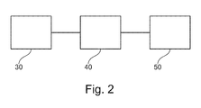
- the method 10 may be performed by an apparatus 40 as illustrated in Figure 2 .
- the apparatus 40 may be positioned between a power source 30 and a motor 50.
- the method 10 comprises a step 12 of receiving data that is indicative of the total electrical active power, P, supplied to the motor 50 by the power source 30. Additionally at step 12, data is received that is indicative of a rotor speed, n r , or rotor frequency, f r , of the axle.
- the electromechanical power, P em supplied to an axle of the motor 50 is determined using the data indicative of the total electrical active power, P.
- the angular rotor frequency, ⁇ r of the axle is determined using the data indicative of rotor speed, n r , or rotor frequency, f r , of the axle.
- the electromechanical axle torque, T em is determined at step 20.
- the electromechanical axle torque, T em is estimated using only data relating to the total electrical active power, P, supplied to the motor 50 by the power source and the rotor speed, n r , or rotor frequency, f r , of the axle.
- this data may be received without interrupting the operation of the motor 50.
- data indicative of the total electrical active power, P, supplied to the motor 50 is obtained by measuring the total electrical active power, P, supplied to the motor 50.
- the total electrical active power, P, supplied to the motor 50 may be determined by measurement of the instantaneous motor voltage and instantaneous motor current on each connected phase of the motor 50.
- the total electrical active power, P, supplied to the motor 50 may be derived using the measured voltages and currents.
- the voltage and/or current may be measured in accordance with IEC 61000-4-30 which is incorporated herein by reference, and/or the total electrical active power, P, may be calculated in accordance with IEEE Std 1459 which is also incorporated herein by reference.
- the mechanical power at the axle of a motor arises due to the electrical active power, P , supplied to the motor. However, not all electrical active power, P, is converted into mechanical power.
- the total electrical active power may therefore be decomposed into three categories, namely (i) electrical active power components positively contributing to mechanical power, (ii) electrical active power negatively contributing to mechanical power, and (iii) electrical active power components not contributing to mechanical power.
- the total electrical active power, P may be decomposed into its individual frequency components.
- this decomposition may be achieved by Fourier analysis.
- this decomposition may be achieved by a fast Fourier transform (FFT) in accordance with the standard IEC 61000-4-7 which is incorporated herein by reference.
- FFT fast Fourier transform
- the fundamental frequency is typically the mains frequency (e.g. 50 Hz or 60 Hz), however, in the case of electronic variable speed drive circuits, the fundamental frequency may be a varying frequency.
- the fundamental component P 1 may be further decomposed into its symmetrical components using the established method symmetrical decomposition (originally proposed by C. L. Fortescue).
- the power components not contributing to the mechanical power at the axle may, for example, generate heat, noise or mechanical malfunction, but contribute neither positively nor negatively to the mechanical power supplied to the axle.
- one method for determining the electromechanical power, P em is to measure or otherwise obtain data indicative of the total electrical active power, P, supplied to the axle (e.g., by measuring the instantaneous voltage and current as described above), and then decomposing the total active power, P, to obtain the components required to determine P em .
- Any method or apparatus in which data that is indicative of the total electrical active power, P, is received and then used to determine electromechanical power, P em may be used within the scope of the present disclosure.
- the rotor speed, n r , or rotor frequency, f r , of the axle may be ascertained by receiving data indicative of the slip, s, and the synchronous speed, n s , or frequency, f s .
- the rotor speed, n r , or rotor frequency, f r , of the axle may be ascertained by receiving data indicative of the slip, s, the fundamental electrical frequency, f 1 , and the number of poles of the motor, p.
- the nominal speed n nom and nominal frequency f nom are quantities defined on the motor nameplate (also known as the motor type shield or motor rating plate) found on most, if not all, motors (typically listed simply as "speed” and "frequency").
- ⁇ f 2. ⁇ f / f 1 , where ⁇ f is the frequency shift due to rotor slip.
- ⁇ f (and f 1 , if unknown) can be obtained by analysis of the frequency spectrum of the motor current.
- Figure 3 shows an example of a motor current frequency spectrum where the fundamental frequency, f 1 , is 60 Hz. On either side of the fundamental frequency, f 1 , there is a notable sideband frequency that is shifted relative to the fundamental frequency, f 1 , by ⁇ f.
- analysis of the frequency spectrum can provide the value of ⁇ f.
- the resolution of the frequency spectrum should be sufficiently great.
- a resolution of 0.1 to 0.5 Hz is sufficient.
- the sideband signals may be significantly lower than the signal at the fundamental frequency, f 1
- the frequency spectrum is preferably obtained with a sufficiently great dynamic range to permit the sidebands to be accurately identified.
- the sidebands are approximately 60 dB lower than the fundamental component, f 1 .
- ⁇ r 2. ⁇ .f r
- ⁇ r 2. ⁇ . 1 - s .2. f 1 / p .
- the angular rotor frequency, ⁇ r may be determined.
- the electromechanical axle torque, T em P em / ⁇ r .
- Certain methods according to embodiments of the present disclosure are particularly suited to calculating electromechanical axle torque in asynchronous motors.
- the skilled person will appreciate that for synchronous motors, the effects of slip will not apply.
- the apparatus 40 may be any suitable apparatus for obtaining the required data and determining electromechanical axle torque, T em , in accordance with methods according to embodiments of the present disclosure.
- the apparatus 40 may include any suitable means, sensor, or system for measuring the instantaneous voltage and current on each connected phase of the motor 50.
- the apparatus 40 may include a control means in the form of a control unit that comprises one or more processors for executing computer software instructions that may be arranged, when executed, to perform a method according to an embodiment of the present disclosure.
- the software instructions may be stored in a non-transitory computer-readable medium, such as a memory of the control unit.
- the control unit may be communicably coupled to the means, sensor or system (if present) for measuring the instantaneous voltage and current on each connected phase of the motor 50.
- the apparatus 40 may include a display for displaying information, which may include, for example, the calculated electromechanical axle torque, T em .
- the apparatus may include one or more transmitters and/or receivers for transmitting and/or receiving data.
- the apparatus 40 may be configured to transmit data indicative of the electromechanical axle torque, T em .
Landscapes
- Engineering & Computer Science (AREA)
- Power Engineering (AREA)
- Physics & Mathematics (AREA)
- General Physics & Mathematics (AREA)
- Control Of Ac Motors In General (AREA)
- Tests Of Circuit Breakers, Generators, And Electric Motors (AREA)
Abstract
Description
- This present disclosure relates to a method and apparatus for estimating torque, and, in particular, to a method and apparatus for estimating the torque of an axle of a running motor.
- In many applications, it is useful to know the torque of a running motor. One known method of measuring torque involves the use of one or more sensors mechanically coupled to a motor shaft. However, there are certain drawbacks associated with the use of torque measuring sensors. In particular, the sensors need to be built into the rotating equipment which is often mechanically difficult, impractical, or, simply, impossible. In certain applications, the presence of the sensor in the mechanical system can interfere with the motor's operation. For example, in high-speed spindle applications, mechanical sensors can introduce an imbalance into the system (in addition to other issues). Additionally, torque sensors are often expensive.
- It is also known to use indirect measurements to determine torque. For example, the "Steinmetz equivalent circuit" may be used to describe how an induction motor's electrical input is transformed into useful mechanical energy output. The parameters of the Steinmetz equivalent circuit can be obtained by starting the motor in a "no load" condition and in a "locked rotor" condition. However, both conditions are disruptive to normal operation of the motor since they each require the motor to be in a non-running state.
- Another method of obtaining the Steinmetz equivalent circuit parameters is based on analysis of the motor start-up current by digital signal processing (DSP) analysis. This method involves a learning period for each individual motor and also requires an interruption of the normal operation of the motor system.
-
US Patent No. 6,505,132 (Takaku ) describes a detection device for detecting instantaneously generated torque and an average generated torque of a three-phase motor. In advance of determining the instantaneously generated torque, the described device is required to detect a "no load" current of the motor. - There therefore exists a need for a method and/or apparatus for estimating the torque of a running motor which does not interfere with the operation of the motor.
- It is an object of certain embodiments of the present disclosure to overcome at least some disadvantages associated with the prior art.
- Aspects of the present invention are defined in the appended claims.
- In accordance with a first aspect disclosed herein, there is provided a method of estimating the torque of an axle of a running motor, comprising:
- receiving data indicative of the total electrical active power, P, supplied to the motor;
- determining the electromechanical power, Pem, supplied to the axle using the data indicative of the total electrical active power, P;
- receiving data indicative of a rotor speed, nr, or rotor frequency, fr, of the axle;
- determining an angular rotor frequency, ωr, of the axle using the data indicative of the rotor speed, nr, or rotor frequency, fr, of the axle; and
- determining electromechanical axle torque, Tem, using the determined electromechanical power, Pem, and the determined angular rotor frequency, ωr.
- Data indicative of the total electrical active power, P, supplied to the motor may be obtained by measuring the total electrical active power, P, supplied to the motor. Measuring the total electrical active power, P, supplied to the motor may include measuring one or both of an instantaneous motor voltage and an instantaneous motor current on each connected phase of the motor.
- Receiving data indicative of the total electrical active power, P, may include receiving data indicative of one or more frequency components, P1, P2, P3, P4,..., of the total electrical active power, P, and receiving data indicative of symmetrical components, P+, P-, of the fundamental frequency component, P1. Data indicative of one or more frequency components, P1, P2, P3, P4,..., of the total electrical active power, P, may be obtained by Fourier analysis of total electrical active power, P, and/or data indicative of symmetrical components, P+, P-, of the fundamental frequency component, P1, may be obtained by symmetrical decomposition of the fundamental frequency component, P1.
- Receiving data indicative of a rotor speed, nr, or rotor frequency, fr, of the axle may include receiving data indicative of one or more of the fundamental electrical frequency, f1, of the current supplied to the motor, the load dependent slip, s, of the motor, the frequency shift, Δf, due to rotor slip, and the number of poles, p, of the motor. The method may further include the step of determining the rotor speed, nr, or rotor frequency, fr, of the axle, where fr (Hz) = (1-s).fs = (1-s).2.f1/p = nr(rpm)/60, and fs is the synchronous frequency of the motor. Additionally or alternatively, the method may further include the step of determining the number of poles, p, of the motor, where p = INTEGER((120.fnom)/nnom), where nnom is the nominal speed of the motor operating at its nominal frequency, fnom.
- The method may further include the step of determining the load dependent slip, s, by analysis of a frequency spectrum of the current supplied to the motor.
- The frequency shift, Δf, due to rotor slip, and the fundamental electrical frequency, f1, of the current supplied to the motor may be determined from the frequency spectrum of the current supplied to the motor, and the load dependent slip, s, is determined as s = 2. Δf/ f1.
- The method may further comprise the step of creating a frequency spectrum of the current supplied to the motor.
- The angular rotor frequency, ωr, of the axle may be determined by calculating ωr (rad/s) = 2.π.fr = 4.π.(1-s).f1/p.
- The electromechanical axle torque, Tem, may be determined by calculating Tem = Pem/ ωr.
- The motor may be an asynchronous induction motor.
- In accordance with a second aspect of the present disclosure, there is provided an apparatus configured to carry out any of the methods described above in relation to the first aspect of the present disclosure.
- Embodiments of the disclosure are further described hereinafter with reference to the accompanying drawings, in which:
-
Figure 1 shows a method according to an embodiment of the present disclosure; -
Figure 2 shows a schematic diagram of an apparatus according to an embodiment of the present disclosure; and -
Figure 3 shows a frequency spectrum associated with the motor current. - Embodiments of the present disclosure provide a method and apparatus for estimating the torque of an axle of a running motor. Advantageously, the method and apparatus may be used to estimate torque without interrupting operation of the motor.
-
Figure 1 illustrates amethod 10 of determining the electromechanical torque, Tem, of an axle of a running motor. - The
method 10 may be performed by anapparatus 40 as illustrated inFigure 2 . Theapparatus 40 may be positioned between apower source 30 and amotor 50. - Returning to
Figure 1 , themethod 10 comprises astep 12 of receiving data that is indicative of the total electrical active power, P, supplied to themotor 50 by thepower source 30. Additionally atstep 12, data is received that is indicative of a rotor speed, nr, or rotor frequency, fr, of the axle. Atstep 14, the electromechanical power, Pem, supplied to an axle of themotor 50 is determined using the data indicative of the total electrical active power, P. Additionally, atstep 16, the angular rotor frequency, ωr, of the axle is determined using the data indicative of rotor speed, nr, or rotor frequency, fr, of the axle. Using the determined electromechanical power, Pem, and the determined angular rotor frequency, ωr, the electromechanical axle torque, Tem, is determined atstep 20. - Therefore, the electromechanical axle torque, Tem, is estimated using only data relating to the total electrical active power, P, supplied to the
motor 50 by the power source and the rotor speed, nr, or rotor frequency, fr, of the axle. Advantageously, this data may be received without interrupting the operation of themotor 50. - In at least one embodiment, data indicative of the total electrical active power, P, supplied to the
motor 50 is obtained by measuring the total electrical active power, P, supplied to themotor 50. For example, the total electrical active power, P, supplied to themotor 50 may be determined by measurement of the instantaneous motor voltage and instantaneous motor current on each connected phase of themotor 50. In particular, the total electrical active power, P, supplied to themotor 50 may be derived using the measured voltages and currents. For example, the voltage and/or current may be measured in accordance with IEC 61000-4-30 which is incorporated herein by reference, and/or the total electrical active power, P, may be calculated in accordance with IEEE Std 1459 which is also incorporated herein by reference. - The mechanical power at the axle of a motor arises due to the electrical active power, P , supplied to the motor. However, not all electrical active power, P, is converted into mechanical power. The total electrical active power may therefore be decomposed into three categories, namely (i) electrical active power components positively contributing to mechanical power, (ii) electrical active power negatively contributing to mechanical power, and (iii) electrical active power components not contributing to mechanical power.
- The total electrical active power, P, may be decomposed into its individual frequency components. For example, this decomposition may be achieved by Fourier analysis. In a particularly preferable embodiment, this decomposition may be achieved by a fast Fourier transform (FFT) in accordance with the standard IEC 61000-4-7 which is incorporated herein by reference. Once decomposed, the total electrical active power, P, may be expressed as a series of harmonic components:

- The fundamental component P1 may be further decomposed into its symmetrical components using the established method symmetrical decomposition (originally proposed by C. L. Fortescue). In particular, the fundamental component P1 may be decomposed as follows:

where P+ is the positive sequence power, P- is the negative sequence power and P0 is the zero sequence power as described by Fortescue. - Substituting this expression for P1 into the decomposed series for total active electrical power, P, and terminating the series at the 25th harmonic component gives:

- As noted above, it is understood that certain terms of this expression provide a positive contribution to the mechanical power at the axle, whilst certain terms provide a negative contribution or do not contribute at all. For example, the fundamental wave revolves synchronously at the synchronous speed, ns, whereas the 3rd, 5th, 7th....harmonics may rotate in the forward or backward direction at speeds of ns/3, ns/5, ns/7,..., respectively. Even harmonics do not contribute to torque. The following table demonstrates how certain harmonics contribute positively or negatively (or not at all) to the torque (in respect of odd harmonics up to the 25th).
Harmonic Total phase shift (degrees) Nearest whole cycle (degrees) Effective phase shift Torque 1 120 0 +120 Pos 3 360 360 0 n/a 5 600 720 -120 Neg 7 840 720 +120 Pos 9 1080 1080 0 n/a 11 1320 1440 -120 Neg 13 1560 1440 +120 Pos 15 1800 1800 0 n/a 17 2040 2160 -120 Neg 19 2280 2160 +120 Pos 21 2520 2520 0 n/a 23 2760 2880 -120 Neg 25 3000 2880 +120 Pos - Considering the above, the following relationships apply (considering a limited series):
Positive contribution: Ppos = P+ + P7 + P13 + P19; Negative contribution: Pneg = P- + P5 + P11 + P17 + P23; No contribution: all remaining power components. - The power components not contributing to the mechanical power at the axle may, for example, generate heat, noise or mechanical malfunction, but contribute neither positively nor negatively to the mechanical power supplied to the axle.
- The electromechanical power, Pem, may be expressed as:

- Therefore, one method for determining the electromechanical power, Pem, is to measure or otherwise obtain data indicative of the total electrical active power, P, supplied to the axle (e.g., by measuring the instantaneous voltage and current as described above), and then decomposing the total active power, P, to obtain the components required to determine Pem. Any method or apparatus in which data that is indicative of the total electrical active power, P, is received and then used to determine electromechanical power, Pem, may be used within the scope of the present disclosure.
- As described above, step 12 also includes receiving data that is indicative of a rotor speed, nr, or rotor frequency, fr, of the axle (nr (rpm) = 60.fr (Hz)). The rotor speed, nr, may be expressed as:

where s is the load dependent slip of the motor and ns is the synchronous speed (i.e., the speed that the motor would run at without slip). Similarly, the rotor frequency, fr, may be expressed as:
where fs is the synchronous frequency, and ns (rpm) = 60.fs (Hz). Therefore, the rotor speed, nr, or rotor frequency, fr, of the axle may be ascertained by receiving data indicative of the slip, s, and the synchronous speed, ns, or frequency, fs. The synchronous speed, ns, may be expressed as:

- Therefore, the rotor speed, nr, or rotor frequency, fr, of the axle may be ascertained by receiving data indicative of the slip, s, the fundamental electrical frequency, f1, and the number of poles of the motor, p.
- The number of motor poles, p, can be deduced from the nominal speed nnom of the motor at the nominal frequency fnom, (which is usually 50 Hz or 60 Hz) by the expression:

where the INTEGER function truncates the result. - The nominal speed nnom and nominal frequency fnom, are quantities defined on the motor nameplate (also known as the motor type shield or motor rating plate) found on most, if not all, motors (typically listed simply as "speed" and "frequency").
- If the load dependent slip, s, is unknown, it may be calculated using the expression:

where Δf is the frequency shift due to rotor slip. Δf (and f1, if unknown) can be obtained by analysis of the frequency spectrum of the motor current.Figure 3 shows an example of a motor current frequency spectrum where the fundamental frequency, f1, is 60 Hz. On either side of the fundamental frequency, f1, there is a notable sideband frequency that is shifted relative to the fundamental frequency, f1, by ±Δf. Thus, analysis of the frequency spectrum can provide the value of Δf. In order to successfully derive Δf from a measured frequency spectrum, the resolution of the frequency spectrum should be sufficiently great. In certain preferable embodiments, a resolution of 0.1 to 0.5 Hz is sufficient. Also, given that the sideband signals may be significantly lower than the signal at the fundamental frequency, f1, the frequency spectrum is preferably obtained with a sufficiently great dynamic range to permit the sidebands to be accurately identified. In the example shown inFigure 3 , the sidebands are approximately 60 dB lower than the fundamental component, f1. - Considering the above expression for the rotor frequency, fr, and substituting the expression for the synchronous frequency, fs, provides:

- Given that the angular rotor frequency, ωr, is defined as ωr = 2.π.fr, it may be expressed (in rad/s) as:

- Therefore, simply by analyzing the motor current frequency spectrum and obtaining data indicative of the nominal speed nnom and nominal frequency fnom of the motor (which may be readily obtained from the motor nameplate), the angular rotor frequency, ωr, may be determined.
- Once the electromechanical power, Pem, and the angular rotor frequency, ωr, is determined, the electromechanical axle torque, Tem, of the motor can be calculated using the expression:

- Certain methods according to embodiments of the present disclosure are particularly suited to calculating electromechanical axle torque in asynchronous motors. The skilled person will appreciate that for synchronous motors, the effects of slip will not apply.
- Certain embodiments of the present disclosure comprise apparatus that is configured to carry out the method. Returning to
Figure 2 , theapparatus 40 may be any suitable apparatus for obtaining the required data and determining electromechanical axle torque, Tem, in accordance with methods according to embodiments of the present disclosure. Theapparatus 40 may include any suitable means, sensor, or system for measuring the instantaneous voltage and current on each connected phase of themotor 50. Theapparatus 40 may include a control means in the form of a control unit that comprises one or more processors for executing computer software instructions that may be arranged, when executed, to perform a method according to an embodiment of the present disclosure. The software instructions may be stored in a non-transitory computer-readable medium, such as a memory of the control unit. The control unit may be communicably coupled to the means, sensor or system (if present) for measuring the instantaneous voltage and current on each connected phase of themotor 50. Theapparatus 40 may include a display for displaying information, which may include, for example, the calculated electromechanical axle torque, Tem. The apparatus may include one or more transmitters and/or receivers for transmitting and/or receiving data. For example, theapparatus 40 may be configured to transmit data indicative of the electromechanical axle torque, Tem. - Throughout the description and claims of this specification, the words "comprise" and "contain" and variations of them mean "including but not limited to", and they are not intended to (and do not) exclude other additives, components, integers or steps. Throughout the description and claims of this specification, the singular encompasses the plural unless the context otherwise requires. In particular, where the indefinite article is used, the specification is to be understood as contemplating plurality as well as singularity, unless the context requires otherwise.
- Features, integers, characteristics, compounds, or groups described in conjunction with a particular aspect, embodiment or example disclosed herein are to be understood to be applicable to any other aspect, embodiment or example described herein unless incompatible therewith. All of the features disclosed in this specification (including any accompanying claims, abstract and drawings), and/or all of the steps of any method or process so disclosed, may be combined in any combination, except combinations where at least some of such features and/or steps are mutually exclusive. The invention is not restricted to the details of any foregoing embodiments. The invention extends to any novel one, or any novel combination, of the features disclosed in this specification (including any accompanying claims, abstract and drawings), or to any novel one, or any novel combination, of the steps of any method or process so disclosed.
- The reader's attention is directed to all papers and documents which are filed concurrently with or previous to this specification in connection with this application and which are open to public inspection with this specification, and the contents of all such papers and documents are incorporated herein by reference.
Claims (15)
- A method of estimating the torque of an axle of a running motor, comprising:receiving data indicative of the total electrical active power, P, supplied to the motor;determining the electromechanical power, Pem, supplied to the axle using the data indicative of the total electrical active power, P;receiving data indicative of a rotor speed, nr, or rotor frequency, fr, of the axle;determining an angular rotor frequency, ωr, of the axle using the data indicative of the rotor speed, nr, or rotor frequency, fr, of the axle; anddetermining electromechanical axle torque, Tem, using the determined electromechanical power, Pem, and the determined angular rotor frequency, ωr.
- The method according to claim 1, wherein data indicative of the total electrical active power, P, supplied to the motor is obtained by measuring the total electrical active power, P, supplied to the motor.
- The method according to claim 2, wherein measuring the total electrical active power, P, supplied to the motor includes measuring one or both of an instantaneous motor voltage and an instantaneous motor current on each connected phase of the motor.
- The method according to any preceding claim, where receiving data indicative of the total electrical active power, P, includes receiving data indicative of one or more frequency components, P1, P2, P3, P4,..., of the total electrical active power, P, and receiving data indicative of symmetrical components, P+, P-, of the fundamental frequency component, P1.
- The method according to claim 4, wherein data indicative of one or more frequency components, P1, P2, P3, P4,..., of the total electrical active power, P, is obtained by Fourier analysis of total electrical active power, P, and/or wherein data indicative of symmetrical components, P+, P-, of the fundamental frequency component, P1, is obtained by symmetrical decomposition of the fundamental frequency component, P1.
- The method according to any preceding claim, wherein receiving data indicative of a rotor speed, nr, or rotor frequency, fr, of the axle includes receiving data indicative of one or more of the fundamental electrical frequency, f1, of the current supplied to the motor, the load dependent slip, s, of the motor, the frequency shift, Δf, due to rotor slip, and the number of poles, p, of the motor.
- The method according to claim 6, wherein the method further includes the step of determining the rotor speed, nr, or rotor frequency, fr, of the axle, where fr (Hz) = (1-s).fs = (1-s).2.f1/p = nr(rpm)/60, and fs is the synchronous frequency of the motor.
- The method of claim 6 or 7, wherein the method further includes the step of determining the number of poles, p, of the motor, where p = INTEGER((120.fnom)/nnom), where nnom is the nominal speed of the motor operating at its nominal frequency, fnom.
- The method of any of claims 6 to 8, wherein the method further includes the step of determining the load dependent slip, s, by analysis of a frequency spectrum of the current supplied to the motor.
- The method of claim 9, wherein the frequency shift, Δf, due to rotor slip, and the fundamental electrical frequency, f1, of the current supplied to the motor are determined from the frequency spectrum of the current supplied to the motor, and the load dependent slip, s, is determined as s = 2. Δf/ f1.
- The method of claim 9 or 10, wherein the method further comprises the step of creating a frequency spectrum of the current supplied to the motor.
- The method of any of claims 6 to 11, wherein the angular rotor frequency, ωr, of the axle is determined by calculating ωr (rad/s) = 2.π.fr = 4.π.(1-s).f1/p.
- The method of any preceding claim, wherein the electromechanical axle torque, Tem, is determined by calculating Tem = Pem/ ωr.
- The method according to any preceding claim, wherein the motor is an asynchronous induction motor.
- An apparatus configured to carry out the method of any preceding claim.
Priority Applications (3)
| Application Number | Priority Date | Filing Date | Title |
|---|---|---|---|
| EP14190048.0A EP3012964B1 (en) | 2014-10-23 | 2014-10-23 | Method and apparatus for estimating torque |
| US14/919,547 US10712216B2 (en) | 2014-10-23 | 2015-10-21 | Method and apparatus for estimating torque |
| CN201510692241.1A CN105553376B (en) | 2014-10-23 | 2015-10-23 | Method and device for estimating torque |
Applications Claiming Priority (1)
| Application Number | Priority Date | Filing Date | Title |
|---|---|---|---|
| EP14190048.0A EP3012964B1 (en) | 2014-10-23 | 2014-10-23 | Method and apparatus for estimating torque |
Publications (2)
| Publication Number | Publication Date |
|---|---|
| EP3012964A1 true EP3012964A1 (en) | 2016-04-27 |
| EP3012964B1 EP3012964B1 (en) | 2022-05-11 |
Family
ID=51795517
Family Applications (1)
| Application Number | Title | Priority Date | Filing Date |
|---|---|---|---|
| EP14190048.0A Active EP3012964B1 (en) | 2014-10-23 | 2014-10-23 | Method and apparatus for estimating torque |
Country Status (3)
| Country | Link |
|---|---|
| US (1) | US10712216B2 (en) |
| EP (1) | EP3012964B1 (en) |
| CN (1) | CN105553376B (en) |
Cited By (1)
| Publication number | Priority date | Publication date | Assignee | Title |
|---|---|---|---|---|
| DE112018002428B4 (en) | 2017-06-09 | 2025-08-21 | Caterpillar Inc. | COMPENSATION OF A VARIABLE DC LINK VOLTAGE WHEN ESTIMATING THE POWER OF A SWITCHED RELUCTANCE MOTOR |
Families Citing this family (2)
| Publication number | Priority date | Publication date | Assignee | Title |
|---|---|---|---|---|
| EP3907568A1 (en) * | 2020-05-08 | 2021-11-10 | Siemens Aktiengesellschaft | Method and systems for providing a simulation model of an electric rotary machine |
| CN114598192B (en) * | 2021-02-04 | 2025-09-30 | 长城汽车股份有限公司 | Method and device for determining motor torque |
Citations (3)
| Publication number | Priority date | Publication date | Assignee | Title |
|---|---|---|---|---|
| US5057760A (en) * | 1985-01-31 | 1991-10-15 | Aeg Westinghouse Transportation Systems, Inc. | Torque determination for control of an induction motor apparatus |
| US6505132B1 (en) | 1999-12-27 | 2003-01-07 | Kaneo Takaku | High-precision instantaneously generated torque detection device for three-phase motor |
| US20120239348A1 (en) * | 2011-03-14 | 2012-09-20 | General Electric Company | Condition monitoring of mechanical drive train coupled with electrical machines |
Family Cites Families (7)
| Publication number | Priority date | Publication date | Assignee | Title |
|---|---|---|---|---|
| CA1296051C (en) | 1985-01-31 | 1992-02-18 | Lalan G. Miller | Torque determination for control of an induction motor apparatus |
| CN1067744A (en) | 1991-06-08 | 1993-01-06 | 桂徐福泉 | Method and device for measuring electric power and electric energy |
| JP2007222918A (en) | 2006-02-24 | 2007-09-06 | Jfe Steel Kk | Slip detection method and slip prevention method in width reduction press equipment |
| US20100169030A1 (en) * | 2007-05-24 | 2010-07-01 | Alexander George Parlos | Machine condition assessment through power distribution networks |
| US8473228B2 (en) * | 2009-05-29 | 2013-06-25 | General Electric Company | Detection of rotor side anomaly in an induction machine |
| CN101788604A (en) | 2010-01-19 | 2010-07-28 | 河北省电力研究院 | Electric power and electric quantity measuring method based on frequency domain analysis and sequence component analysis |
| US8766578B2 (en) | 2012-02-27 | 2014-07-01 | Canadian Space Agency | Method and apparatus for high velocity ripple suppression of brushless DC motors having limited drive/amplifier bandwidth |
-
2014
- 2014-10-23 EP EP14190048.0A patent/EP3012964B1/en active Active
-
2015
- 2015-10-21 US US14/919,547 patent/US10712216B2/en active Active
- 2015-10-23 CN CN201510692241.1A patent/CN105553376B/en active Active
Patent Citations (3)
| Publication number | Priority date | Publication date | Assignee | Title |
|---|---|---|---|---|
| US5057760A (en) * | 1985-01-31 | 1991-10-15 | Aeg Westinghouse Transportation Systems, Inc. | Torque determination for control of an induction motor apparatus |
| US6505132B1 (en) | 1999-12-27 | 2003-01-07 | Kaneo Takaku | High-precision instantaneously generated torque detection device for three-phase motor |
| US20120239348A1 (en) * | 2011-03-14 | 2012-09-20 | General Electric Company | Condition monitoring of mechanical drive train coupled with electrical machines |
Non-Patent Citations (1)
| Title |
|---|
| KRAL C ET AL: "Detection of mechanical imbalances during transient torque operating conditions", DIAGNOSTICS FOR ELECTRIC MACHINES, POWER ELECTRONICS AND DRIVES, 2005. DEMPED 2005. 5TH IEEE INTERNATIONAL SYMPOSIUM ON, IEEE, PISCATAWAY, NJ, USA, 7 September 2005 (2005-09-07), pages 1 - 4, XP031354951, ISBN: 978-0-7803-9124-6 * |
Cited By (1)
| Publication number | Priority date | Publication date | Assignee | Title |
|---|---|---|---|---|
| DE112018002428B4 (en) | 2017-06-09 | 2025-08-21 | Caterpillar Inc. | COMPENSATION OF A VARIABLE DC LINK VOLTAGE WHEN ESTIMATING THE POWER OF A SWITCHED RELUCTANCE MOTOR |
Also Published As
| Publication number | Publication date |
|---|---|
| US20160116354A1 (en) | 2016-04-28 |
| US10712216B2 (en) | 2020-07-14 |
| CN105553376B (en) | 2020-10-20 |
| CN105553376A (en) | 2016-05-04 |
| EP3012964B1 (en) | 2022-05-11 |
Similar Documents
| Publication | Publication Date | Title |
|---|---|---|
| Alwodai et al. | A comparison of different techniques for induction motor rotor fault diagnosis | |
| CN102947711B (en) | Rotating speed detection system in AC induction motor and method | |
| JP5932022B2 (en) | Method and apparatus for monitoring the state of an electromechanical system | |
| EP2790028B1 (en) | Broken rotor bar detection based on current signature analysis of an electric machine | |
| Kia et al. | Torsional vibration assessment using induction machine electromagnetic torque estimation | |
| US10658961B2 (en) | Method for identifying the discrete instantaneous angular speed of an electromechanical system | |
| US20160266208A1 (en) | Fault detection and diagnosis in an induction motor | |
| EP2942867B1 (en) | Induction motor speed estimation | |
| US20220170987A1 (en) | Abnormality diagnosis device and abnormality diagnosis method | |
| US10877098B2 (en) | Method for detecting a fault in an electrical machine | |
| US9852837B2 (en) | Multi-winding high sensitivity current transformer | |
| JP2020153965A (en) | Abnormality diagnosis device and abnormality diagnosis method | |
| Bourogaoui et al. | An effective encoder fault detection in PMSM drives at different speed ranges | |
| EP3012964B1 (en) | Method and apparatus for estimating torque | |
| TWI612765B (en) | Method for determining the intrinsic feature quantity of a three-phase induction motor | |
| Khater et al. | Proposed fault diagnostics of a broken rotor bar induction motor fed from PWM inverter | |
| CN107210691B (en) | Angle error correction device for position detector and angle error correction method | |
| Arabaci | An artificial neural network approach for sensorless speed estimation via rotor slot harmonics | |
| JP5332667B2 (en) | Induction motor control device | |
| Choi et al. | Broken rotor bar detection in AC induction motors using cascaded flux-current state observer | |
| Ouachtouk et al. | WIRELESS HEALTH MONITORING SYSTEM FOR ROTOR ECCENTRICITY FAULTS DETECTION IN INDUCTION MACHINE. | |
| Montero et al. | Estimation of torque sharing for industrial dual induction motor drives under special current sensor configuration | |
| Seferian et al. | Comprehensive induction motor fault diagnosis using extremum seeking control | |
| US20250244206A1 (en) | Electrical machine monitoring | |
| Odavic et al. | Real-time fault diagnostics for a permanent magnet synchronous motor drive for aerospace applications |
Legal Events
| Date | Code | Title | Description |
|---|---|---|---|
| PUAI | Public reference made under article 153(3) epc to a published international application that has entered the european phase |
Free format text: ORIGINAL CODE: 0009012 |
|
| AK | Designated contracting states |
Kind code of ref document: A1 Designated state(s): AL AT BE BG CH CY CZ DE DK EE ES FI FR GB GR HR HU IE IS IT LI LT LU LV MC MK MT NL NO PL PT RO RS SE SI SK SM TR |
|
| AX | Request for extension of the european patent |
Extension state: BA ME |
|
| STAA | Information on the status of an ep patent application or granted ep patent |
Free format text: STATUS: REQUEST FOR EXAMINATION WAS MADE |
|
| 17P | Request for examination filed |
Effective date: 20161027 |
|
| RBV | Designated contracting states (corrected) |
Designated state(s): AL AT BE BG CH CY CZ DE DK EE ES FI FR GB GR HR HU IE IS IT LI LT LU LV MC MK MT NL NO PL PT RO RS SE SI SK SM TR |
|
| STAA | Information on the status of an ep patent application or granted ep patent |
Free format text: STATUS: EXAMINATION IS IN PROGRESS |
|
| 17Q | First examination report despatched |
Effective date: 20201021 |
|
| GRAP | Despatch of communication of intention to grant a patent |
Free format text: ORIGINAL CODE: EPIDOSNIGR1 |
|
| STAA | Information on the status of an ep patent application or granted ep patent |
Free format text: STATUS: GRANT OF PATENT IS INTENDED |
|
| INTG | Intention to grant announced |
Effective date: 20220218 |
|
| GRAS | Grant fee paid |
Free format text: ORIGINAL CODE: EPIDOSNIGR3 |
|
| GRAA | (expected) grant |
Free format text: ORIGINAL CODE: 0009210 |
|
| STAA | Information on the status of an ep patent application or granted ep patent |
Free format text: STATUS: THE PATENT HAS BEEN GRANTED |
|
| AK | Designated contracting states |
Kind code of ref document: B1 Designated state(s): AL AT BE BG CH CY CZ DE DK EE ES FI FR GB GR HR HU IE IS IT LI LT LU LV MC MK MT NL NO PL PT RO RS SE SI SK SM TR |
|
| REG | Reference to a national code |
Ref country code: GB Ref legal event code: FG4D |
|
| REG | Reference to a national code |
Ref country code: CH Ref legal event code: EP |
|
| REG | Reference to a national code |
Ref country code: AT Ref legal event code: REF Ref document number: 1492343 Country of ref document: AT Kind code of ref document: T Effective date: 20220515 |
|
| REG | Reference to a national code |
Ref country code: DE Ref legal event code: R096 Ref document number: 602014083673 Country of ref document: DE |
|
| REG | Reference to a national code |
Ref country code: IE Ref legal event code: FG4D |
|
| REG | Reference to a national code |
Ref country code: LT Ref legal event code: MG9D |
|
| REG | Reference to a national code |
Ref country code: NL Ref legal event code: MP Effective date: 20220511 |
|
| REG | Reference to a national code |
Ref country code: AT Ref legal event code: MK05 Ref document number: 1492343 Country of ref document: AT Kind code of ref document: T Effective date: 20220511 |
|
| PG25 | Lapsed in a contracting state [announced via postgrant information from national office to epo] |
Ref country code: SE Free format text: LAPSE BECAUSE OF FAILURE TO SUBMIT A TRANSLATION OF THE DESCRIPTION OR TO PAY THE FEE WITHIN THE PRESCRIBED TIME-LIMIT Effective date: 20220511 Ref country code: PT Free format text: LAPSE BECAUSE OF FAILURE TO SUBMIT A TRANSLATION OF THE DESCRIPTION OR TO PAY THE FEE WITHIN THE PRESCRIBED TIME-LIMIT Effective date: 20220912 Ref country code: NO Free format text: LAPSE BECAUSE OF FAILURE TO SUBMIT A TRANSLATION OF THE DESCRIPTION OR TO PAY THE FEE WITHIN THE PRESCRIBED TIME-LIMIT Effective date: 20220811 Ref country code: NL Free format text: LAPSE BECAUSE OF FAILURE TO SUBMIT A TRANSLATION OF THE DESCRIPTION OR TO PAY THE FEE WITHIN THE PRESCRIBED TIME-LIMIT Effective date: 20220511 Ref country code: LT Free format text: LAPSE BECAUSE OF FAILURE TO SUBMIT A TRANSLATION OF THE DESCRIPTION OR TO PAY THE FEE WITHIN THE PRESCRIBED TIME-LIMIT Effective date: 20220511 Ref country code: HR Free format text: LAPSE BECAUSE OF FAILURE TO SUBMIT A TRANSLATION OF THE DESCRIPTION OR TO PAY THE FEE WITHIN THE PRESCRIBED TIME-LIMIT Effective date: 20220511 Ref country code: GR Free format text: LAPSE BECAUSE OF FAILURE TO SUBMIT A TRANSLATION OF THE DESCRIPTION OR TO PAY THE FEE WITHIN THE PRESCRIBED TIME-LIMIT Effective date: 20220812 Ref country code: FI Free format text: LAPSE BECAUSE OF FAILURE TO SUBMIT A TRANSLATION OF THE DESCRIPTION OR TO PAY THE FEE WITHIN THE PRESCRIBED TIME-LIMIT Effective date: 20220511 Ref country code: ES Free format text: LAPSE BECAUSE OF FAILURE TO SUBMIT A TRANSLATION OF THE DESCRIPTION OR TO PAY THE FEE WITHIN THE PRESCRIBED TIME-LIMIT Effective date: 20220511 Ref country code: BG Free format text: LAPSE BECAUSE OF FAILURE TO SUBMIT A TRANSLATION OF THE DESCRIPTION OR TO PAY THE FEE WITHIN THE PRESCRIBED TIME-LIMIT Effective date: 20220811 Ref country code: AT Free format text: LAPSE BECAUSE OF FAILURE TO SUBMIT A TRANSLATION OF THE DESCRIPTION OR TO PAY THE FEE WITHIN THE PRESCRIBED TIME-LIMIT Effective date: 20220511 |
|
| PG25 | Lapsed in a contracting state [announced via postgrant information from national office to epo] |
Ref country code: RS Free format text: LAPSE BECAUSE OF FAILURE TO SUBMIT A TRANSLATION OF THE DESCRIPTION OR TO PAY THE FEE WITHIN THE PRESCRIBED TIME-LIMIT Effective date: 20220511 Ref country code: PL Free format text: LAPSE BECAUSE OF FAILURE TO SUBMIT A TRANSLATION OF THE DESCRIPTION OR TO PAY THE FEE WITHIN THE PRESCRIBED TIME-LIMIT Effective date: 20220511 Ref country code: LV Free format text: LAPSE BECAUSE OF FAILURE TO SUBMIT A TRANSLATION OF THE DESCRIPTION OR TO PAY THE FEE WITHIN THE PRESCRIBED TIME-LIMIT Effective date: 20220511 Ref country code: IS Free format text: LAPSE BECAUSE OF FAILURE TO SUBMIT A TRANSLATION OF THE DESCRIPTION OR TO PAY THE FEE WITHIN THE PRESCRIBED TIME-LIMIT Effective date: 20220911 |
|
| PG25 | Lapsed in a contracting state [announced via postgrant information from national office to epo] |
Ref country code: SM Free format text: LAPSE BECAUSE OF FAILURE TO SUBMIT A TRANSLATION OF THE DESCRIPTION OR TO PAY THE FEE WITHIN THE PRESCRIBED TIME-LIMIT Effective date: 20220511 Ref country code: SK Free format text: LAPSE BECAUSE OF FAILURE TO SUBMIT A TRANSLATION OF THE DESCRIPTION OR TO PAY THE FEE WITHIN THE PRESCRIBED TIME-LIMIT Effective date: 20220511 Ref country code: RO Free format text: LAPSE BECAUSE OF FAILURE TO SUBMIT A TRANSLATION OF THE DESCRIPTION OR TO PAY THE FEE WITHIN THE PRESCRIBED TIME-LIMIT Effective date: 20220511 Ref country code: EE Free format text: LAPSE BECAUSE OF FAILURE TO SUBMIT A TRANSLATION OF THE DESCRIPTION OR TO PAY THE FEE WITHIN THE PRESCRIBED TIME-LIMIT Effective date: 20220511 Ref country code: DK Free format text: LAPSE BECAUSE OF FAILURE TO SUBMIT A TRANSLATION OF THE DESCRIPTION OR TO PAY THE FEE WITHIN THE PRESCRIBED TIME-LIMIT Effective date: 20220511 Ref country code: CZ Free format text: LAPSE BECAUSE OF FAILURE TO SUBMIT A TRANSLATION OF THE DESCRIPTION OR TO PAY THE FEE WITHIN THE PRESCRIBED TIME-LIMIT Effective date: 20220511 |
|
| REG | Reference to a national code |
Ref country code: DE Ref legal event code: R097 Ref document number: 602014083673 Country of ref document: DE |
|
| PLBE | No opposition filed within time limit |
Free format text: ORIGINAL CODE: 0009261 |
|
| STAA | Information on the status of an ep patent application or granted ep patent |
Free format text: STATUS: NO OPPOSITION FILED WITHIN TIME LIMIT |
|
| PG25 | Lapsed in a contracting state [announced via postgrant information from national office to epo] |
Ref country code: AL Free format text: LAPSE BECAUSE OF FAILURE TO SUBMIT A TRANSLATION OF THE DESCRIPTION OR TO PAY THE FEE WITHIN THE PRESCRIBED TIME-LIMIT Effective date: 20220511 |
|
| 26N | No opposition filed |
Effective date: 20230214 |
|
| PG25 | Lapsed in a contracting state [announced via postgrant information from national office to epo] |
Ref country code: SI Free format text: LAPSE BECAUSE OF FAILURE TO SUBMIT A TRANSLATION OF THE DESCRIPTION OR TO PAY THE FEE WITHIN THE PRESCRIBED TIME-LIMIT Effective date: 20220511 Ref country code: MC Free format text: LAPSE BECAUSE OF FAILURE TO SUBMIT A TRANSLATION OF THE DESCRIPTION OR TO PAY THE FEE WITHIN THE PRESCRIBED TIME-LIMIT Effective date: 20220511 |
|
| REG | Reference to a national code |
Ref country code: CH Ref legal event code: PL |
|
| REG | Reference to a national code |
Ref country code: BE Ref legal event code: MM Effective date: 20221031 |
|
| PG25 | Lapsed in a contracting state [announced via postgrant information from national office to epo] |
Ref country code: LU Free format text: LAPSE BECAUSE OF NON-PAYMENT OF DUE FEES Effective date: 20221023 |
|
| PG25 | Lapsed in a contracting state [announced via postgrant information from national office to epo] |
Ref country code: LI Free format text: LAPSE BECAUSE OF NON-PAYMENT OF DUE FEES Effective date: 20221031 Ref country code: CH Free format text: LAPSE BECAUSE OF NON-PAYMENT OF DUE FEES Effective date: 20221031 |
|
| PG25 | Lapsed in a contracting state [announced via postgrant information from national office to epo] |
Ref country code: BE Free format text: LAPSE BECAUSE OF NON-PAYMENT OF DUE FEES Effective date: 20221031 |
|
| PG25 | Lapsed in a contracting state [announced via postgrant information from national office to epo] |
Ref country code: IE Free format text: LAPSE BECAUSE OF NON-PAYMENT OF DUE FEES Effective date: 20221023 |
|
| PG25 | Lapsed in a contracting state [announced via postgrant information from national office to epo] |
Ref country code: IT Free format text: LAPSE BECAUSE OF FAILURE TO SUBMIT A TRANSLATION OF THE DESCRIPTION OR TO PAY THE FEE WITHIN THE PRESCRIBED TIME-LIMIT Effective date: 20220511 |
|
| PG25 | Lapsed in a contracting state [announced via postgrant information from national office to epo] |
Ref country code: HU Free format text: LAPSE BECAUSE OF FAILURE TO SUBMIT A TRANSLATION OF THE DESCRIPTION OR TO PAY THE FEE WITHIN THE PRESCRIBED TIME-LIMIT; INVALID AB INITIO Effective date: 20141023 |
|
| PG25 | Lapsed in a contracting state [announced via postgrant information from national office to epo] |
Ref country code: CY Free format text: LAPSE BECAUSE OF FAILURE TO SUBMIT A TRANSLATION OF THE DESCRIPTION OR TO PAY THE FEE WITHIN THE PRESCRIBED TIME-LIMIT Effective date: 20220511 |
|
| PG25 | Lapsed in a contracting state [announced via postgrant information from national office to epo] |
Ref country code: MK Free format text: LAPSE BECAUSE OF FAILURE TO SUBMIT A TRANSLATION OF THE DESCRIPTION OR TO PAY THE FEE WITHIN THE PRESCRIBED TIME-LIMIT Effective date: 20220511 |
|
| PG25 | Lapsed in a contracting state [announced via postgrant information from national office to epo] |
Ref country code: TR Free format text: LAPSE BECAUSE OF FAILURE TO SUBMIT A TRANSLATION OF THE DESCRIPTION OR TO PAY THE FEE WITHIN THE PRESCRIBED TIME-LIMIT Effective date: 20220511 |
|
| PG25 | Lapsed in a contracting state [announced via postgrant information from national office to epo] |
Ref country code: MT Free format text: LAPSE BECAUSE OF FAILURE TO SUBMIT A TRANSLATION OF THE DESCRIPTION OR TO PAY THE FEE WITHIN THE PRESCRIBED TIME-LIMIT Effective date: 20220511 |
|
| PG25 | Lapsed in a contracting state [announced via postgrant information from national office to epo] |
Ref country code: BG Free format text: LAPSE BECAUSE OF FAILURE TO SUBMIT A TRANSLATION OF THE DESCRIPTION OR TO PAY THE FEE WITHIN THE PRESCRIBED TIME-LIMIT Effective date: 20220511 |
|
| PG25 | Lapsed in a contracting state [announced via postgrant information from national office to epo] |
Ref country code: BG Free format text: LAPSE BECAUSE OF FAILURE TO SUBMIT A TRANSLATION OF THE DESCRIPTION OR TO PAY THE FEE WITHIN THE PRESCRIBED TIME-LIMIT Effective date: 20220511 |
|
| PGFP | Annual fee paid to national office [announced via postgrant information from national office to epo] |
Ref country code: DE Payment date: 20251029 Year of fee payment: 12 |
|
| PGFP | Annual fee paid to national office [announced via postgrant information from national office to epo] |
Ref country code: GB Payment date: 20251027 Year of fee payment: 12 |
|
| PGFP | Annual fee paid to national office [announced via postgrant information from national office to epo] |
Ref country code: FR Payment date: 20251027 Year of fee payment: 12 |