EP3012336A1 - Low carbon steel and cemented carbide wear part - Google Patents
Low carbon steel and cemented carbide wear part Download PDFInfo
- Publication number
- EP3012336A1 EP3012336A1 EP15194415.4A EP15194415A EP3012336A1 EP 3012336 A1 EP3012336 A1 EP 3012336A1 EP 15194415 A EP15194415 A EP 15194415A EP 3012336 A1 EP3012336 A1 EP 3012336A1
- Authority
- EP
- European Patent Office
- Prior art keywords
- cemented carbide
- inserts
- carbon steel
- low
- wear part
- Prior art date
- Legal status (The legal status is an assumption and is not a legal conclusion. Google has not performed a legal analysis and makes no representation as to the accuracy of the status listed.)
- Granted
Links
Images

Classifications
-
- B—PERFORMING OPERATIONS; TRANSPORTING
- B22—CASTING; POWDER METALLURGY
- B22D—CASTING OF METALS; CASTING OF OTHER SUBSTANCES BY THE SAME PROCESSES OR DEVICES
- B22D19/00—Casting in, on, or around objects which form part of the product
- B22D19/0081—Casting in, on, or around objects which form part of the product pretreatment of the insert, e.g. for enhancing the bonding between insert and surrounding cast metal
-
- B—PERFORMING OPERATIONS; TRANSPORTING
- B22—CASTING; POWDER METALLURGY
- B22D—CASTING OF METALS; CASTING OF OTHER SUBSTANCES BY THE SAME PROCESSES OR DEVICES
- B22D19/00—Casting in, on, or around objects which form part of the product
- B22D19/02—Casting in, on, or around objects which form part of the product for making reinforced articles
-
- B—PERFORMING OPERATIONS; TRANSPORTING
- B22—CASTING; POWDER METALLURGY
- B22D—CASTING OF METALS; CASTING OF OTHER SUBSTANCES BY THE SAME PROCESSES OR DEVICES
- B22D19/00—Casting in, on, or around objects which form part of the product
- B22D19/06—Casting in, on, or around objects which form part of the product for manufacturing or repairing tools
-
- B—PERFORMING OPERATIONS; TRANSPORTING
- B22—CASTING; POWDER METALLURGY
- B22D—CASTING OF METALS; CASTING OF OTHER SUBSTANCES BY THE SAME PROCESSES OR DEVICES
- B22D19/00—Casting in, on, or around objects which form part of the product
- B22D19/14—Casting in, on, or around objects which form part of the product the objects being filamentary or particulate in form
-
- C—CHEMISTRY; METALLURGY
- C22—METALLURGY; FERROUS OR NON-FERROUS ALLOYS; TREATMENT OF ALLOYS OR NON-FERROUS METALS
- C22C—ALLOYS
- C22C29/00—Alloys based on carbides, oxides, nitrides, borides, or silicides, e.g. cermets, or other metal compounds, e.g. oxynitrides, sulfides
- C22C29/02—Alloys based on carbides, oxides, nitrides, borides, or silicides, e.g. cermets, or other metal compounds, e.g. oxynitrides, sulfides based on carbides or carbonitrides
-
- C—CHEMISTRY; METALLURGY
- C22—METALLURGY; FERROUS OR NON-FERROUS ALLOYS; TREATMENT OF ALLOYS OR NON-FERROUS METALS
- C22C—ALLOYS
- C22C47/00—Making alloys containing metallic or non-metallic fibres or filaments
- C22C47/02—Pretreatment of the fibres or filaments
- C22C47/04—Pretreatment of the fibres or filaments by coating, e.g. with a protective or activated covering
-
- C—CHEMISTRY; METALLURGY
- C22—METALLURGY; FERROUS OR NON-FERROUS ALLOYS; TREATMENT OF ALLOYS OR NON-FERROUS METALS
- C22C—ALLOYS
- C22C47/00—Making alloys containing metallic or non-metallic fibres or filaments
- C22C47/08—Making alloys containing metallic or non-metallic fibres or filaments by contacting the fibres or filaments with molten metal, e.g. by infiltrating the fibres or filaments placed in a mould
-
- C—CHEMISTRY; METALLURGY
- C22—METALLURGY; FERROUS OR NON-FERROUS ALLOYS; TREATMENT OF ALLOYS OR NON-FERROUS METALS
- C22C—ALLOYS
- C22C49/00—Alloys containing metallic or non-metallic fibres or filaments
- C22C49/02—Alloys containing metallic or non-metallic fibres or filaments characterised by the matrix material
- C22C49/08—Iron group metals
-
- C—CHEMISTRY; METALLURGY
- C22—METALLURGY; FERROUS OR NON-FERROUS ALLOYS; TREATMENT OF ALLOYS OR NON-FERROUS METALS
- C22C—ALLOYS
- C22C49/00—Alloys containing metallic or non-metallic fibres or filaments
- C22C49/14—Alloys containing metallic or non-metallic fibres or filaments characterised by the fibres or filaments
-
- C—CHEMISTRY; METALLURGY
- C22—METALLURGY; FERROUS OR NON-FERROUS ALLOYS; TREATMENT OF ALLOYS OR NON-FERROUS METALS
- C22C—ALLOYS
- C22C29/00—Alloys based on carbides, oxides, nitrides, borides, or silicides, e.g. cermets, or other metal compounds, e.g. oxynitrides, sulfides
- C22C29/02—Alloys based on carbides, oxides, nitrides, borides, or silicides, e.g. cermets, or other metal compounds, e.g. oxynitrides, sulfides based on carbides or carbonitrides
- C22C29/06—Alloys based on carbides, oxides, nitrides, borides, or silicides, e.g. cermets, or other metal compounds, e.g. oxynitrides, sulfides based on carbides or carbonitrides based on carbides, but not containing other metal compounds
- C22C29/08—Alloys based on carbides, oxides, nitrides, borides, or silicides, e.g. cermets, or other metal compounds, e.g. oxynitrides, sulfides based on carbides or carbonitrides based on carbides, but not containing other metal compounds based on tungsten carbide
Definitions
- the present disclosure relates to a wear part of cemented carbide (CC) particles cast into low carbon steel having a unique product design and performance and a wear part having inserts made of the cast CC particles and low carbon steel.
- CC cemented carbide
- the compound material concept is especially suitable for drill bits used in mining and oil and gas drilling, rock milling tools, tunnel boring machine cutters/discs, impellers, and wear parts used in machine parts, instruments, tools etc., and particularly in components exposed to great wear.
- a method of forming a high wear resistant, high strength wear part of another embodiment includes the steps of providing a quantity of cemented carbide particles and positioning the cemented carbide particles into a mold.
- the cemented carbide particles are encapsulated with the molten low-carbon steel alloy to cast a matrix of cemented carbide particles and low-carbon steel alloy.
- a wear part of yet another embodiment, having high wear resistance and strength is provided.
- the wear part includes a body with a plurality of inserts of cemented carbide particles cast into a low-carbon steel alloy disposed in the body.
- a method of forming a high wear resistant, high strength wear part of still another embodiment includes the steps of forming a plurality of cemented carbide inserts, the inserts being formed by encapsulating cemented carbide particles with a molten low-carbon steel alloy to cast a matrix of cemented carbide particles and low-carbon steel alloy, the low-carbon steel alloy having a carbon content of about 1 to about 1.5 weight percent.
- Each of the plurality of cemented carbide inserts are coated with at least one layer of oxidation protection/chemical resistant material.
- the plurality of inserts are directly fixed onto a mold corresponding to the shape of the wear part.
- the cemented carbide inserts are encapsulated with the molten low-carbon steel alloy to cast the cemented carbide inserts with the low-carbon steel alloy.
- One aspect of the present invention relates to the casting of cemented carbide particles/bodies into low carbon steel to manufacture unique products and designs having improved wear resistance performance.
- This compound material is especially suitable for drill bits used in mining and oil and gas drilling, rock milling tools, TBM-cutters/discs, impellers, sliding wear parts, and wear parts used in machine parts, instruments, tools, etc., and particularly in components exposed to great wear. It should be appreciated that other products or parts are contemplated by the present invention.
- a body 10 of the wear part includes cemented carbide particles 12 and a binder of low-carbon steel alloy 14.
- the cemented carbide particles can be cast with low-carbon steel alloy 14.
- cemented carbide particles are used as wear resistance material and can be formed using a variety of techniques.
- the cemented carbide is present as pieces, crushed material, powder, pressed bodies, particles or some other shape.
- the cemented carbide which contains at least one carbide besides a binder metal, is normally of WC-Co-type with possible additions of carbides of Ti, Ta, Nb or other metals, but also hard metal containing other carbides and/or nitrides and binder metals may be suitable. In exceptional cases also pure carbides or other hard principles, i.e. without any binder phase, can be used.
- the cemented carbide could also be replaced by cermet depending on the wear application.
- a cermet is a lighter metal matrix material normally used in wear parts with high demands on oxidation and corrosion resistance.
- the low-carbon steel alloy could be replaced by another heat resistant alloy e.g. Ni-based alloy, Inconel etc.
- the particle size and the content of crushed carbide particles will influence the wettability of the steel due to the difference in the thermal conductivity between the two materials. A satisfactory wetting or metallurgical bond between the hard material and the steel could be maintained in preheated molds with enough high proportion of molten steel.
- the CC particles have a granular size so that a good balance with regards to the heat capacity and the heat conductivity between the steel and the CC particles could be obtained for the best possible wetting of the steel onto the CC particles.
- the size volume of the CC particles should be about 0.3 to about 20 cm 3 .
- the CC particles should be exposed at the surface of the wear part. Therefore, the shape of the particles is important to maintain a large wear flat surface area and a good bonding to the steel matrix.
- the thickness of the particles should be about 5 to about 15 mm.
- the cast cemented carbide particles (“CC particles”) 12 are surrounded and encapsulated by the low-carbon steel alloy 14 to form a matrix.
- the CC particles cast into low carbon steel have a good fitting to the steel without voids.
- the carbon content of the steel is about 0.1 to about 1.5 weight % of carbon. Carbon contents in this range will raise the melting point of the steel/alloy above the melting point of the binder-phase in the CC particles.
- the CC particles are coated with alumina.
- the molten low-carbon steel 14 is cast with CC particles 12 to form the matrix.
- CC particles 12 are coated with a thin coating 16 of alumina.
- the protective coating of alumina is applied preferably with a CVD coating technique and the coating thickness should be very thin if it is applied onto another hard coating, e.g. TiN, (Ti,Al)N, TiC).
- the CC particles have an alumina coating thickness of about 1 to about 8 ⁇ m.
- the coating could have multiple layers and especially with CC particles having a binder phase content of Ni it is important to have a pre-layer of, e.g. TiN, to make the alumina coating possible.
- other coating techniques can be used, for example, microwave, plasma, PVD, etc.
- the alumina coating 16 will prevent the steel from reacting with the CC and the dissolution of the CC is restricted to the parts of the CC particles where the alumina coating has a hole that provides a "leakage.”
- the controlled leakage of the steel makes a surface zone 18 about the CC particles with an alloying of the binder-phase with content of Iron (Fe) and other alloying elements from the steel, e.g. Cr.
- An intermediate reaction zone 20, shown at the corners of the particle, is restricted to the parts in the steel where the holes in the alumina coating are found.
- the difference in the volume expansion coefficient between the steel and the CC particles provides favorable compressive stresses around the CC particle.
- the alloying of the binder-phase in the outer zone of the CC particle gives also compressive stresses to the "core" of the CC particle.
- the dissolution of the CC is controlled and the surface zone 18 is formed between the steel and the CC where the alumina coating has holes.
- the wear part of the present invention can be formed by known casting techniques.
- the CC particles can be positioned within a mold that corresponds to the desired shape of the part.
- the CC particles are preferably positioned in the mold so as to be at the surface of the resulting wear part. In this position the CC particles are exposed to air.
- the molten low-carbon steel alloy is then delivered to the mold to form the matrix of particles and alloy.
- the casting of the matrix is heated to about 1550 to about1600° C. After the casting it can be subjected to hardening, annealing and tempering as is known in the art.
- a wear part 22 having a body 10 can include a plurality of CC inserts 24 located therein.
- Inserts 24 are formed of cemented carbide particles cast with low-carbon steel alloy as described above.
- Inserts 24 include a coating 26 to prevent oxidation.
- Coating 26 is made of alumina, for example Al 2 O 3 , and reacts with the steel without harming the bonding between the steel and the CC particles, as described above.
- the CC inserts should be exposed at the surface of the wear part. Therefore, the shape of the particles is important to maintain a large wear flat surface area and a good bonding to the steel matrix.
- the thickness of the inserts should be about 5 to about 15 mm.
- the alumina coating 26 will prevent the steel from reacting with the CC and the dissolution of the CC is restricted to the parts of the CC inserts where the alumina coating has a hole that provides "leakage.”
- the protective coating of alumina is applied preferably with the CVD coating technique and the coating thickness should be very thin if it is applied onto another hard coating, e.g. TiN, (Ti,Al)N, TiC). It is preferable that the CC inserts have an alumina coating thickness of about 1 to about 8 ⁇ m.
- the coating could have multiple layers and especially with CC inserts having a binder phase content of Ni it is important to have a pre-layer of, e.g. TiN, to make the alumina coating possible.
- the coating can be applied via a CVD coating technique or other coating techniques such as plasma, microwave, PVD etc.
- the wear part of an embodiment can be formed by known casting techniques.
- the coated CC inserts can be positioned within a mold that corresponds to the desired shape of the part.
- the CC bodies may be positioned in the mold so as to be at the surface of the resulting wear part. In this position the CC inserts are exposed to air.
- the molten low-carbon steel alloy is then delivered to the mold to form the matrix of particles and alloy.
- the casting of the matrix is heated to about 1550 to about1600° C. After the casting it can be subjected to hardening, annealing and tempering as is known in the art.
- the CC-inserts may be directly fixed to the surface of the mold, i.e., with screws, net, nail, etc., without the need for the steel melt to completely cover the particles/inserts.
- This technique makes it possible to directly form, for example, a drill bit with CC inserts or buttons fitted to the steel body.
- the casting process with hardening, annealing and tempering has shown that the CC survives in the wear part due to the alumina coating of the CC inserts.
- Tamping tools according to the invention were manufactured by casting the complete tool by slip casting.
- the finished tamping tool had a steel shaft and a wear paddle covered by square type cemented carbide inserts with a side length of 28 mm and a thickness of 7mm.
- the inserts of cemented carbide were prepared by a conventional powder metallurgical technique, having a composition of 8 wt% Co and the remaining being WC with a grain size of 1 ⁇ m.
- the carbon content was 5.55 wt %.
- the sintered cemented carbide inserts were alumina-coated in a CVD-reactor at 920 °C. After the CVD-process the inserts were completely covered by a black alumina coating with a thickness of 4 ⁇ m.
- the inserts were fixed with nails in the mold for the manufacturing of the tamping tool.
- a steel of type CNM85 with a composition of 0.26%C, 1.5% Si, 1.2%Mn, 1.4%Cr, 0.5% Ni, and 0.2%Mo was melted and the melt was poured into the molds at a temperature of 1565°C. After air cooling, the teeth were normalized at 950°C and hardened at 1000°C. Annealing at 250 °C was the final heat treatment step before blasting and grinding the tool to its final shape. The hardness of the steel in the finished tools was between 45 and 55 HRC.
- the inserts were directly press-fitted into the mold before the cast procedure. After the casting the shaft was ground to the finished dimension of the rock milling cutter.
- Fig. 4 shows a cast 28 of high strength steel having CC inserts 24' and made according to the present invention after casting at 1565°C, hardening, annealing, tempering and blasting. The inserts were fitted directly to the mold with screws.
- the carbide specimens show a good wetting without oxidation.
- Fig. 4 further shows that the CC inserts 24' have not just survived the casting process, but the shape of the CC inserts are kept after the casting.
- the hole 29 in the right insert originates from a screw that did not survive oxidation during the cast operation.
- the test shows that it is possible to apply CC-insert to the surface of low carbon steel. Results show that the cemented carbide wear part with the high strength and wear resistant steel alloy according to the invention has high reliability and strength with a wear performance increase that is 10 times higher than the steel commodity product.
- FIGs. 5A and 5B two different parts were tested: an Alumina coated specimen ( Fig. 5A ) and a TiN specimen ( Fig. 5B ).
- the same type of specimens of a CC grade keeping 6% Cobalt+WC were completely coated with two types of hard coatings for an oxidation test.
- the coating was maintained within a CVD-reactor for both variants of inserts. Both types of inserts were completely coated prior to the oxidation test.
- the oxidation results from 5 hours at 920°C show that the alumina-coated CC specimen ( Fig. 5A ) does not show any oxidation. However, the TiN-coated specimen does. Thus, the casting result has shown a good wetting of the steel around the alumina-coated carbide substrate.
- maintaining the compound between the low-carbon steel and the CC-particles/bodies is due to the high oxidation/chemical resistance of the CC particles/bodies.
- the high chemical resistance is maintained by providing an alumina coating on the CC-bodies /particles.
- the alumina coating is maintained preferably by a CVD-coating technique.
- the coating could also be applied with other techniques, e.g. PVD in a fluidized bed.
Landscapes
- Engineering & Computer Science (AREA)
- Mechanical Engineering (AREA)
- Chemical & Material Sciences (AREA)
- Materials Engineering (AREA)
- Metallurgy (AREA)
- Organic Chemistry (AREA)
- Manufacturing & Machinery (AREA)
- Other Surface Treatments For Metallic Materials (AREA)
- Manufacture Of Alloys Or Alloy Compounds (AREA)
- Percussive Tools And Related Accessories (AREA)
- Powder Metallurgy (AREA)
Abstract
Description
- The present disclosure relates to a wear part of cemented carbide (CC) particles cast into low carbon steel having a unique product design and performance and a wear part having inserts made of the cast CC particles and low carbon steel. The compound material concept is especially suitable for drill bits used in mining and oil and gas drilling, rock milling tools, tunnel boring machine cutters/discs, impellers, and wear parts used in machine parts, instruments, tools etc., and particularly in components exposed to great wear.
- A wear part of an embodiment having high wear resistance and strength composed of a compound body of cemented carbide particles cast with a low-carbon steel alloy, wherein the low-carbon steel alloy has a carbon content corresponding to a carbon equivalent Ceq=wt%C+0.3(wt%Si+wt%P) of about 0.1 to about 1.5 weight percent.
- A method of forming a high wear resistant, high strength wear part of another embodiment includes the steps of providing a quantity of cemented carbide particles and positioning the cemented carbide particles into a mold. Molten low-carbon steel alloy, having a carbon content corresponding to a carbon equivalent Ceq=wt%C+0.3(wt%Si+wt%P) of about 0.1 to about 1.5 wt% is delivered into the mold. The cemented carbide particles are encapsulated with the molten low-carbon steel alloy to cast a matrix of cemented carbide particles and low-carbon steel alloy.
- A wear part of yet another embodiment, having high wear resistance and strength is provided. The wear part includes a body with a plurality of inserts of cemented carbide particles cast into a low-carbon steel alloy disposed in the body. The low-carbon steel alloy has a carbon content corresponding to a carbon equivalent
Ceq=wt%C+0.3(wt%Si+wt%P) of about 0.1 to about 1.5 weight percent. - A method of forming a high wear resistant, high strength wear part of still another embodiment includes the steps of forming a plurality of cemented carbide inserts, the inserts being formed by encapsulating cemented carbide particles with a molten low-carbon steel alloy to cast a matrix of cemented carbide particles and low-carbon steel alloy, the low-carbon steel alloy having a carbon content of about 1 to about 1.5 weight percent. Each of the plurality of cemented carbide inserts are coated with at least one layer of oxidation protection/chemical resistant material. The plurality of inserts are directly fixed onto a mold corresponding to the shape of the wear part. The cemented carbide inserts are encapsulated with the molten low-carbon steel alloy to cast the cemented carbide inserts with the low-carbon steel alloy.
- These and other objects, features, aspects, and advantages of the present invention will become more apparent from the following detailed description of embodiments relative to the accompanied drawings, in which:
-
-
Fig. 1 is an exemplary microstructure of the cemented carbide particle, low-carbon steel alloy matrix of the present invention. -
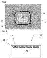
Fig. 2 is an enlarged microstructure of the present invention. -
Fig. 3 is a cross-section of a coated wear part of the present invention. -
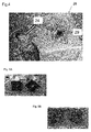
Fig. 4 is a wear part made according to the method of the present invention after casting, hardening, annealing and blasting. -
Figs. 5A and 5B are parts tested for oxidation resistance. - One aspect of the present invention relates to the casting of cemented carbide particles/bodies into low carbon steel to manufacture unique products and designs having improved wear resistance performance. This compound material is especially suitable for drill bits used in mining and oil and gas drilling, rock milling tools, TBM-cutters/discs, impellers, sliding wear parts, and wear parts used in machine parts, instruments, tools, etc., and particularly in components exposed to great wear. It should be appreciated that other products or parts are contemplated by the present invention.
- Referring to
Fig 1 , abody 10 of the wear part includes cementedcarbide particles 12 and a binder of low-carbon steel alloy 14. The cemented carbide particles can be cast with low-carbon steel alloy 14. Low-carbon steel alloy has a carbon content corresponding to a carbon equivalent Ceq=wt%C+0.3(wt%Si+wt%P) of about 0.1 to about 1.5 weight percent. - As is known, cemented carbide particles are used as wear resistance material and can be formed using a variety of techniques. For example, the cemented carbide is present as pieces, crushed material, powder, pressed bodies, particles or some other shape. The cemented carbide, which contains at least one carbide besides a binder metal, is normally of WC-Co-type with possible additions of carbides of Ti, Ta, Nb or other metals, but also hard metal containing other carbides and/or nitrides and binder metals may be suitable. In exceptional cases also pure carbides or other hard principles, i.e. without any binder phase, can be used. The cemented carbide could also be replaced by cermet depending on the wear application. A cermet is a lighter metal matrix material normally used in wear parts with high demands on oxidation and corrosion resistance. The low-carbon steel alloy could be replaced by another heat resistant alloy e.g. Ni-based alloy, Inconel etc.
- The particle size and the content of crushed carbide particles will influence the wettability of the steel due to the difference in the thermal conductivity between the two materials. A satisfactory wetting or metallurgical bond between the hard material and the steel could be maintained in preheated molds with enough high proportion of molten steel.
- In order to provide the best wear and resistance properties, it is preferable that the CC particles have a granular size so that a good balance with regards to the heat capacity and the heat conductivity between the steel and the CC particles could be obtained for the best possible wetting of the steel onto the CC particles. The size volume of the CC particles should be about 0.3 to about 20 cm3.
- To maintain the best wear resistance of the hard compound material, the CC particles should be exposed at the surface of the wear part. Therefore, the shape of the particles is important to maintain a large wear flat surface area and a good bonding to the steel matrix. The thickness of the particles should be about 5 to about 15 mm.
- As shown in
Fig. 1 , the cast cemented carbide particles ("CC particles") 12 are surrounded and encapsulated by the low-carbon steel alloy 14 to form a matrix. The CC particles cast into low carbon steel have a good fitting to the steel without voids. The carbon content of the steel is about 0.1 to about 1.5 weight % of carbon. Carbon contents in this range will raise the melting point of the steel/alloy above the melting point of the binder-phase in the CC particles. To prevent the dissolution of the CC particles, the CC particles are coated with alumina. - As will be described further herein, the molten low-
carbon steel 14 is cast withCC particles 12 to form the matrix. Referring toFig 2 ,CC particles 12 are coated with athin coating 16 of alumina. The protective coating of alumina is applied preferably with a CVD coating technique and the coating thickness should be very thin if it is applied onto another hard coating, e.g. TiN, (Ti,Al)N, TiC). It is preferable that the CC particles have an alumina coating thickness of about 1 to about 8 µm. The coating could have multiple layers and especially with CC particles having a binder phase content of Ni it is important to have a pre-layer of, e.g. TiN, to make the alumina coating possible. It should be appreciated that other coating techniques can be used, for example, microwave, plasma, PVD, etc. - During the casting process, the
alumina coating 16 will prevent the steel from reacting with the CC and the dissolution of the CC is restricted to the parts of the CC particles where the alumina coating has a hole that provides a "leakage." The controlled leakage of the steel makes asurface zone 18 about the CC particles with an alloying of the binder-phase with content of Iron (Fe) and other alloying elements from the steel, e.g. Cr. Anintermediate reaction zone 20, shown at the corners of the particle, is restricted to the parts in the steel where the holes in the alumina coating are found. The difference in the volume expansion coefficient between the steel and the CC particles provides favorable compressive stresses around the CC particle. The alloying of the binder-phase in the outer zone of the CC particle gives also compressive stresses to the "core" of the CC particle. - Due to the alumina coating, the dissolution of the CC is controlled and the
surface zone 18 is formed between the steel and the CC where the alumina coating has holes. The surface zone keeps the content of brittle hard phases (eta-phase/M6C carbides, M=W, Co, Fe and dendrites of W-alloys) and is not beneficial for the wear resistance of the wear part. Just a small portion of the CC is dissolved atsurface zone 18, about 0.1 to about 0.3 mm thick zone of the CC particles where a hole in the alumina coating has occurred. No observed transition "zone" could be found between the alumina coating and steel. - The wear part of the present invention can be formed by known casting techniques. The CC particles can be positioned within a mold that corresponds to the desired shape of the part. The CC particles are preferably positioned in the mold so as to be at the surface of the resulting wear part. In this position the CC particles are exposed to air. The molten low-carbon steel alloy is then delivered to the mold to form the matrix of particles and alloy. The casting of the matrix is heated to about 1550 to about1600° C. After the casting it can be subjected to hardening, annealing and tempering as is known in the art. Referring to
Fig. 3 , awear part 22 having abody 10 can include a plurality of CC inserts 24 located therein.Inserts 24 are formed of cemented carbide particles cast with low-carbon steel alloy as described above. The low-carbon steel alloy has a carbon content corresponding to a carbon equivalent Ceq=wt%C+0.3(wt%Si+wt%P) of about 0.1 to about 1.5 weight percent. -
Inserts 24 include acoating 26 to prevent oxidation.Coating 26 is made of alumina, for example Al2O3, and reacts with the steel without harming the bonding between the steel and the CC particles, as described above. - The CC inserts should be exposed at the surface of the wear part. Therefore, the shape of the particles is important to maintain a large wear flat surface area and a good bonding to the steel matrix. The thickness of the inserts should be about 5 to about 15 mm.
- As described above, during the casting process the
alumina coating 26 will prevent the steel from reacting with the CC and the dissolution of the CC is restricted to the parts of the CC inserts where the alumina coating has a hole that provides "leakage." The protective coating of alumina is applied preferably with the CVD coating technique and the coating thickness should be very thin if it is applied onto another hard coating, e.g. TiN, (Ti,Al)N, TiC). It is preferable that the CC inserts have an alumina coating thickness of about 1 to about 8 µm. The coating could have multiple layers and especially with CC inserts having a binder phase content of Ni it is important to have a pre-layer of, e.g. TiN, to make the alumina coating possible. The coating can be applied via a CVD coating technique or other coating techniques such as plasma, microwave, PVD etc. - The wear part of an embodiment can be formed by known casting techniques. The coated CC inserts can be positioned within a mold that corresponds to the desired shape of the part. The CC bodies may be positioned in the mold so as to be at the surface of the resulting wear part. In this position the CC inserts are exposed to air. The molten low-carbon steel alloy is then delivered to the mold to form the matrix of particles and alloy. The casting of the matrix is heated to about 1550 to about1600° C. After the casting it can be subjected to hardening, annealing and tempering as is known in the art.
- Due to the surface oxidation protection of the alumina coating, the CC-inserts may be directly fixed to the surface of the mold, i.e., with screws, net, nail, etc., without the need for the steel melt to completely cover the particles/inserts. This technique makes it possible to directly form, for example, a drill bit with CC inserts or buttons fitted to the steel body. The casting process with hardening, annealing and tempering has shown that the CC survives in the wear part due to the alumina coating of the CC inserts.
- Tamping tools according to the invention were manufactured by casting the complete tool by slip casting. The finished tamping tool had a steel shaft and a wear paddle covered by square type cemented carbide inserts with a side length of 28 mm and a thickness of 7mm. The inserts of cemented carbide were prepared by a conventional powder metallurgical technique, having a composition of 8 wt% Co and the remaining being WC with a grain size of 1 µm. The carbon content was 5.55 wt %. The sintered cemented carbide inserts were alumina-coated in a CVD-reactor at 920 °C. After the CVD-process the inserts were completely covered by a black alumina coating with a thickness of 4µm.
- The inserts were fixed with nails in the mold for the manufacturing of the tamping tool. A steel of type CNM85 with a composition of 0.26%C, 1.5% Si, 1.2%Mn, 1.4%Cr, 0.5% Ni, and 0.2%Mo was melted and the melt was poured into the molds at a temperature of 1565°C. After air cooling, the teeth were normalized at 950°C and hardened at 1000°C. Annealing at 250 °C was the final heat treatment step before blasting and grinding the tool to its final shape. The hardness of the steel in the finished tools was between 45 and 55 HRC.
- In a second experiment, aimed especially for rock milling, an insert type rock milling cutters was cast into one semi-finished part. Each milling cutter had four cutting inserts of cemented carbide with a binder phase content of 12 wt% Co. The remaining was WC with a grain size of 4 µm. The manufacturing method was the same as Example 1 above and with a steel body of type CNM85. Prior to the casting procedure the cemented carbide inserts were alumina-coated in a CVD reactor according to Example 1.
- The inserts were directly press-fitted into the mold before the cast procedure.
After the casting the shaft was ground to the finished dimension of the rock milling cutter. - In a third experiment aimed especially for rock milling tools, such as point attack tools, an alumina-coated cemented carbide button having a binder phase content of 6 wt% Co and the rest being WC with a grain size between 8 µm was cast. The manufacturing route was the same as Example 1 with a casting procedure of steel type CNM85 to form the semi-finished part. The fitting portion was ground to the finished shape of the point attack tool.
- The wear parts made according to the present disclosure were cast tested.
Fig. 4 shows acast 28 of high strength steel having CC inserts 24' and made according to the present invention after casting at 1565°C, hardening, annealing, tempering and blasting. The inserts were fitted directly to the mold with screws. - The carbide specimens show a good wetting without oxidation.
Fig. 4 further shows that the CC inserts 24' have not just survived the casting process, but the shape of the CC inserts are kept after the casting. Thehole 29 in the right insert originates from a screw that did not survive oxidation during the cast operation. The test shows that it is possible to apply CC-insert to the surface of low carbon steel. Results show that the cemented carbide wear part with the high strength and wear resistant steel alloy according to the invention has high reliability and strength with a wear performance increase that is 10 times higher than the steel commodity product. - Referring to
Figs. 5A and 5B , two different parts were tested: an Alumina coated specimen (Fig. 5A ) and a TiN specimen (Fig. 5B ). The same type of specimens of a CC grade keeping 6% Cobalt+WC were completely coated with two types of hard coatings for an oxidation test. The coating was maintained within a CVD-reactor for both variants of inserts. Both types of inserts were completely coated prior to the oxidation test. - The oxidation results from 5 hours at 920°C show that the alumina-coated CC specimen (
Fig. 5A ) does not show any oxidation. However, the TiN-coated specimen does. Thus, the casting result has shown a good wetting of the steel around the alumina-coated carbide substrate. - It should be appreciated that maintaining the compound between the low-carbon steel and the CC-particles/bodies is due to the high oxidation/chemical resistance of the CC particles/bodies. The high chemical resistance is maintained by providing an alumina coating on the CC-bodies /particles. The alumina coating is maintained preferably by a CVD-coating technique. The coating could also be applied with other techniques, e.g. PVD in a fluidized bed.
- Although the present invention has been described in relation to particular embodiments thereof, many other variations and modifications and other uses will become apparent to those skilled in the art. It is preferred therefore, that the present invention be limited not by the specific disclosure herein, but only by the appended claims.
-
- 1. A wear part having high wear resistance and strength, comprising:
- a body composed of cemented carbide particles cast with a low-carbon steel alloy, wherein said low-carbon steel alloy has a carbon content corresponding to a carbon equivalent Ceq=wt%C+0.3(wt%Si+wt%P) of about 0.1 to about 1.5 weight percent.
- 2. The wear part according to item 1, characterized in that the cemented carbide particles of the body are encapsulated by the low-carbon steel during casting to form a matrix.
- 3. The wear part according to items 1 or 2, characterized in that the cemented carbide particles have a granular size that promotes a balance of heat capacity and heat conductivity between the low-carbon steel alloy and the cemented carbide particles for maximum wetting of the steel alloy onto the cemented carbide particles.
- 4. The wear part according to any of the preceding items, characterized in that the volume of the cemented carbide particles is about 0.3 to about 20 cm3.
- 5. The wear part according to any of the preceding items, further comprising at least one oxidation protection coating disposed on the cemented carbide particles.
- 6. The wear part according to any of the preceding items, characterized in that said at least one coating is alumina.
- 7. The wear part according to any of the preceding items, characterized in that the cemented carbide particles have an alumina coating thickness of about 1 to about 8 µm.
- 8. The wear part according to any of the preceding items, further comprising a plurality of layers of coating on the cemented carbide particles.
- 9. The wear part according to any of the preceding items, characterized in that the cemented carbide particles have a binder phase content of Ni.
- 10. The wear part according to any of the proceeding items, further comprising a pre-layer of TiN coated on the cemented carbide particles underneath the alumina coating.
- 11. The wear part according to any of the preceding items, characterized in that the cemented carbide particles are exposed at a surface of the wear part.
- 12. The wear part according to any of the preceding items, characterized in that the cemented carbide particles have a thickness of about 5 to about 15 mm.
- 13. A method of forming a high wear resistant, high strength wear part comprising the steps of:
- providing a quantity of cemented carbide particles;
- positioning the cemented carbide particles into a mold;
- delivering molten low-carbon steel alloy into the mold, the low-carbon steel alloy having a carbon content of and about 1 to about 1.5 weight percent, and
- encapsulating said cemented carbide particles with said molten low-carbon steel alloy to cast a matrix of cemented carbide particles and low-carbon steel alloy.
- 14. The method according to item 13, further comprising the step of coating the cemented carbide particles with at least one layer of oxidation reducing material.
- 15. The method according to
item 13 or 14, characterized in that the step of coating the cemented carbide particles comprises applying a layer of alumina. - 16. The method according to any one of items 13-15, characterized in that the step of coating comprises applying an alumina coating thickness of about 1 to about 8 µm to the cemented carbide particles.
- 17. The method according to any one of items 13-16, further comprising the step of applying a plurality of layers of coating on the cemented carbide particles.
- 18. A wear part made according to the method of any one of items 13-17.
- 19. A wear part having high wear resistance and strength, comprising:
- a body; and
- a plurality of inserts of cemented carbide particles cast with a low-carbon steel alloy disposed in said body, wherein said low-carbon steel alloy has a carbon content corresponding to a carbon equivalent Ceq=wt%C+0.3(wt%Si+wt%P) of about 0.1 to about 1.5 weight percent.
- 20. The wear part according to item 19, characterized in that the cemented carbide particles of the body are encapsulated by the low-carbon steel during casting to form a matrix.
- 21. The wear part according to
item 19 or 20, characterized in that the cemented carbide particles have a granular size that promotes a balance of heat capacity and heat conductivity between the low-carbon steel alloy and the cemented carbide particles for maximum wetting of the steel alloy onto the cemented carbide particles. - 22. The wear part according to any one of items 19-21, characterized in that the volume of the cemented carbide particles is about 0.3 to about 20 cm3.
- 23. The wear part according to any one of items 19-22, further comprising at least one oxidation reducing coating disposed on each of the plurality of inserts.
- 24. The wear part according to any one of items 19-23, characterized in that said at least one coating is alumina.
- 25. The wear part according to any one of items 19-24, characterized in that each of the plurality of inserts have an alumina coating thickness of about 1 to about 8 µm.
- 26. The wear part according to any one of items 19-25, further comprising a plurality of layers of coating on each of the plurality of inserts.
- 27. The wear part according to any one of items 19-26, characterized in that the plurality of inserts are exposed at a surface of the wear part.
- 28. The wear part according to any one of items 19-27, characterized in that the inserts have a thickness of about 5 to about 15 mm.
- 29. A method of forming a high wear resistant, high strength wear part comprising the steps of:
- forming a plurality of cemented carbide inserts, the inserts being formed by encapsulating cemented carbide particles with a molten low-carbon steel alloy to cast a matrix of cemented carbide particles and low-carbon steel alloy, the low-carbon steel alloy having a carbon content of and about 1 to about 1.5 weight percent;
- coating each of the plurality of cemented carbide inserts with at least one layer of oxidation protection material;
directly fixing the plurality of inserts onto a mold corresponding to the shape of the wear part; and
encapsulating said cemented carbide inserts with said molten low-carbon steel alloy to cast the cemented carbide inserts with the low-carbon steel alloy.
- 30. The method according to
item 29, characterized in that the step of coating the cemented carbide inserts comprises applying a coating of alumina. - 31. The method according to
item 29 or 30, characterized in that the step of coating comprises applying an alumina coating thickness of about 1 to about 8 µm to the cemented carbide inserts. - 32. The method according to any one of items 29-31, further comprising the step of applying a plurality of layers of coating on the cemented carbide inserts.
- 33. A wear part made according to the method of any one of items 29-32.
Claims (11)
- A wear part having high wear resistance and strength, comprising:a body; anda plurality of inserts of cemented carbide particles cast with a low-carbon steel alloy disposed in said body, wherein said low-carbon steel alloy has a carbon content corresponding to a carbon equivalent Ceq=wt%C+0.3(wt%Si+wt%P) of 0.1 to 1.5 weight percent wherein at least one oxidation protection coating is disposed on the inserts.
- The wear part according to claim 1, characterized in that the cemented carbide particles of the body are encapsulated by the low-carbon steel during casting to form a matrix.
- The wear part according to claim 1 or 2, characterized in that the volume of the cemented carbide particles is 0.3 to 20 cm3.
- The wear part according to any one of claims 1-3, characterized in that said at least one oxidation protection coating is alumina.
- The wear part according to claim 4, characterized in that each of the plurality of inserts have an alumina coating thickness of 1 to 8 µm.
- The wear part according to any one of claims 1-5, further comprising a plurality of layers of coating on each of the plurality of inserts.
- The wear part according to any one of claims 1-6, characterized in that the plurality of inserts are exposed at a surface of the wear part.
- The wear part according to any one of claims 1-7, characterized in that the inserts have a thickness of 5 to 15 mm.
- A method of forming a high wear resistant, high strength wear part comprising the steps of:forming a plurality of cemented carbide inserts by encapsulating cemented carbide particles with a molten low-carbon steel alloy to cast a matrix of cemented carbide particles and low-carbon steel alloy, the low-carbon steel alloy having a carbon content corresponding to a carbon equivalent Ceq=wt%C+0.3(wt%Si+wt%P) of 0.1 to 1.5 weight percent;coating each of the plurality of cemented carbide inserts with at least one layer of oxidation protection material;directly fixing the plurality of coated cemented carbide inserts onto a mold corresponding to the shape of the wear part; andencapsulating the plurality of coated cemented carbide inserts with said molten low-carbon steel alloy to cast the cemented carbide inserts with the low-carbon steel alloy.
- The method according to claim 9, characterized in that the step of coating the cemented carbide inserts comprises applying a coating of alumina.
- The method according to claim 10, characterized in that the step of coating comprises applying an alumina coating having a thickness of 1 to 8 µm to the cemented carbide inserts.
Applications Claiming Priority (3)
| Application Number | Priority Date | Filing Date | Title |
|---|---|---|---|
| US201261724122P | 2012-11-08 | 2012-11-08 | |
| PCT/IB2013/059977 WO2014072932A1 (en) | 2012-11-08 | 2013-11-07 | Low carbon steel and cemented carbide wear part |
| EP13802442.7A EP2917379B1 (en) | 2012-11-08 | 2013-11-07 | Low carbon steel and cemented carbide wear part |
Related Parent Applications (2)
| Application Number | Title | Priority Date | Filing Date |
|---|---|---|---|
| EP13802442.7A Division EP2917379B1 (en) | 2012-11-08 | 2013-11-07 | Low carbon steel and cemented carbide wear part |
| EP13802442.7A Division-Into EP2917379B1 (en) | 2012-11-08 | 2013-11-07 | Low carbon steel and cemented carbide wear part |
Publications (2)
| Publication Number | Publication Date |
|---|---|
| EP3012336A1 true EP3012336A1 (en) | 2016-04-27 |
| EP3012336B1 EP3012336B1 (en) | 2019-04-03 |
Family
ID=49726831
Family Applications (2)
| Application Number | Title | Priority Date | Filing Date |
|---|---|---|---|
| EP15194415.4A Active EP3012336B1 (en) | 2012-11-08 | 2013-11-07 | Low carbon steel and cemented carbide wear part |
| EP13802442.7A Active EP2917379B1 (en) | 2012-11-08 | 2013-11-07 | Low carbon steel and cemented carbide wear part |
Family Applications After (1)
| Application Number | Title | Priority Date | Filing Date |
|---|---|---|---|
| EP13802442.7A Active EP2917379B1 (en) | 2012-11-08 | 2013-11-07 | Low carbon steel and cemented carbide wear part |
Country Status (10)
| Country | Link |
|---|---|
| US (1) | US10196712B2 (en) |
| EP (2) | EP3012336B1 (en) |
| JP (1) | JP6281959B2 (en) |
| KR (1) | KR102220849B1 (en) |
| CN (1) | CN104797722B (en) |
| DK (1) | DK2917379T3 (en) |
| ES (2) | ES2609989T3 (en) |
| PL (1) | PL2917379T3 (en) |
| PT (2) | PT2917379T (en) |
| WO (1) | WO2014072932A1 (en) |
Families Citing this family (9)
| Publication number | Priority date | Publication date | Assignee | Title |
|---|---|---|---|---|
| CN106014266B (en) * | 2016-08-02 | 2019-05-10 | 西南石油大学 | A disc cutter compound drill bit suitable for difficult-to-drill formations |
| JP6804143B2 (en) * | 2016-09-30 | 2020-12-23 | 株式会社小松製作所 | Earth and sand wear resistant parts and their manufacturing methods |
| EP3871807A1 (en) * | 2020-02-24 | 2021-09-01 | Parksen Group Pty Ltd | Method for designing a prearranged hard surface or hard points for casting product and corresponding casting |
| EP4121232A4 (en) * | 2020-03-18 | 2024-06-26 | CONV Australia Holding Pty Ltd. | Wear resistant composite |
| CN112522621A (en) * | 2020-11-30 | 2021-03-19 | 自贡硬质合金有限责任公司 | Composite wear-resistant metal block and preparation method thereof |
| CN112975579A (en) * | 2021-02-03 | 2021-06-18 | 安徽绿能技术研究院有限公司 | Wear-resistant corrosion-resistant iron-based material and preparation method thereof |
| CN113414560A (en) * | 2021-06-11 | 2021-09-21 | 湖北金阳石新型耐磨材料科技有限公司 | Technical process for inlaying high-chromium alloy in high-manganese steel substrate |
| JP7795185B2 (en) * | 2021-07-09 | 2026-01-07 | 株式会社木村鋳造所 | Casting method |
| WO2025186846A1 (en) * | 2024-03-07 | 2025-09-12 | F.A.R. - Fonderie Acciaierie Roiale S.P.A. | Metal alloy for a method for producing an article and article thus obtained |
Citations (4)
| Publication number | Priority date | Publication date | Assignee | Title |
|---|---|---|---|---|
| US4146080A (en) * | 1976-03-18 | 1979-03-27 | Permanence Corporation | Composite materials containing refractory metallic carbides and method of forming the same |
| US4499795A (en) * | 1983-09-23 | 1985-02-19 | Strata Bit Corporation | Method of drill bit manufacture |
| US5066546A (en) * | 1989-03-23 | 1991-11-19 | Kennametal Inc. | Wear-resistant steel castings |
| US6139921A (en) * | 1997-11-26 | 2000-10-31 | Sandvik Ab | Method for depositing fine-grained alumina coatings on cutting tools |
Family Cites Families (10)
| Publication number | Priority date | Publication date | Assignee | Title |
|---|---|---|---|---|
| SE399911C (en) * | 1976-02-05 | 1980-02-18 | Sandvik Ab | Wear detail with high durability and good toughness, composed of solid metal and cast iron |
| US4741973A (en) * | 1986-12-15 | 1988-05-03 | United Technologies Corporation | Silicon carbide abrasive particles having multilayered coating |
| US5008132A (en) * | 1989-06-06 | 1991-04-16 | Norton Company | Process for preparing titanium nitride coated silicon carbide materials |
| DE4209975A1 (en) | 1992-03-27 | 1993-09-30 | Krupp Widia Gmbh | Composite body and its use |
| JP2852867B2 (en) * | 1994-05-13 | 1999-02-03 | 株式会社小松製作所 | Method for producing wear-resistant parts and wear-resistant parts |
| CA2289200C (en) * | 1997-05-13 | 2009-08-25 | Richard Edmund Toth | Tough-coated hard powders and sintered articles thereof |
| US6641918B1 (en) * | 1999-06-03 | 2003-11-04 | Powdermet, Inc. | Method of producing fine coated tungsten carbide particles |
| JP2009102709A (en) * | 2007-10-24 | 2009-05-14 | Sumitomo Electric Ind Ltd | LAMINATE STRUCTURE-TYPE CEMENTED CARBIDE, ITS MANUFACTURING METHOD, AND TOOL FORMED BY THE Cemented Carbide |
| WO2009061274A1 (en) * | 2007-11-09 | 2009-05-14 | Sandvik Intellectual Property Ab | Casted in cemented carbide components |
| US8342268B2 (en) * | 2008-08-12 | 2013-01-01 | Smith International, Inc. | Tough carbide bodies using encapsulated carbides |
-
2013
- 2013-11-07 KR KR1020157012017A patent/KR102220849B1/en active Active
- 2013-11-07 EP EP15194415.4A patent/EP3012336B1/en active Active
- 2013-11-07 PL PL13802442T patent/PL2917379T3/en unknown
- 2013-11-07 US US14/440,910 patent/US10196712B2/en active Active
- 2013-11-07 EP EP13802442.7A patent/EP2917379B1/en active Active
- 2013-11-07 PT PT138024427T patent/PT2917379T/en unknown
- 2013-11-07 DK DK13802442.7T patent/DK2917379T3/en active
- 2013-11-07 PT PT15194415T patent/PT3012336T/en unknown
- 2013-11-07 WO PCT/IB2013/059977 patent/WO2014072932A1/en not_active Ceased
- 2013-11-07 ES ES13802442.7T patent/ES2609989T3/en active Active
- 2013-11-07 CN CN201380058624.2A patent/CN104797722B/en active Active
- 2013-11-07 ES ES15194415T patent/ES2734997T3/en active Active
- 2013-11-07 JP JP2015541278A patent/JP6281959B2/en active Active
Patent Citations (4)
| Publication number | Priority date | Publication date | Assignee | Title |
|---|---|---|---|---|
| US4146080A (en) * | 1976-03-18 | 1979-03-27 | Permanence Corporation | Composite materials containing refractory metallic carbides and method of forming the same |
| US4499795A (en) * | 1983-09-23 | 1985-02-19 | Strata Bit Corporation | Method of drill bit manufacture |
| US5066546A (en) * | 1989-03-23 | 1991-11-19 | Kennametal Inc. | Wear-resistant steel castings |
| US6139921A (en) * | 1997-11-26 | 2000-10-31 | Sandvik Ab | Method for depositing fine-grained alumina coatings on cutting tools |
Also Published As
| Publication number | Publication date |
|---|---|
| KR20150070231A (en) | 2015-06-24 |
| KR102220849B1 (en) | 2021-02-25 |
| EP3012336B1 (en) | 2019-04-03 |
| PL2917379T3 (en) | 2017-03-31 |
| DK2917379T3 (en) | 2017-01-30 |
| EP2917379A1 (en) | 2015-09-16 |
| PT2917379T (en) | 2017-01-06 |
| PT3012336T (en) | 2019-06-21 |
| US10196712B2 (en) | 2019-02-05 |
| EP2917379B1 (en) | 2016-10-19 |
| JP2015537118A (en) | 2015-12-24 |
| CN104797722A (en) | 2015-07-22 |
| ES2734997T3 (en) | 2019-12-13 |
| ES2609989T3 (en) | 2017-04-25 |
| US20150299827A1 (en) | 2015-10-22 |
| JP6281959B2 (en) | 2018-02-21 |
| CN104797722B (en) | 2017-03-22 |
| WO2014072932A1 (en) | 2014-05-15 |
Similar Documents
| Publication | Publication Date | Title |
|---|---|---|
| EP3012336B1 (en) | Low carbon steel and cemented carbide wear part | |
| EP2347024B1 (en) | A hard-metal | |
| US9109413B2 (en) | Methods of forming components and portions of earth-boring tools including sintered composite materials | |
| EP2324140B1 (en) | Wear part with hard facing | |
| EP2462083B1 (en) | Tough coated hard particles consolidated in a tough matrix material | |
| EP1009545B1 (en) | Tough-coated hard powders and sintered articles thereof | |
| AU2010200206A1 (en) | Matrix drill bit with dual surface compositions and methods of manufacture | |
| CA2529995A1 (en) | Cemented carbide inserts for earth-boring bits | |
| CN105339587A (en) | ring tool | |
| NZ200325A (en) | Producing wear-resistant composite incorporating cemented tungsten carbide insert | |
| WO2017011415A1 (en) | Infiltrated cutting tools and related methods | |
| WO2017011825A1 (en) | Composite downhole tool | |
| WO2019113219A1 (en) | Wear part and method of making the same | |
| HK1127629A (en) | Tough-coated hard powders and sintered articles thereof |
Legal Events
| Date | Code | Title | Description |
|---|---|---|---|
| PUAI | Public reference made under article 153(3) epc to a published international application that has entered the european phase |
Free format text: ORIGINAL CODE: 0009012 |
|
| AC | Divisional application: reference to earlier application |
Ref document number: 2917379 Country of ref document: EP Kind code of ref document: P |
|
| AK | Designated contracting states |
Kind code of ref document: A1 Designated state(s): AL AT BE BG CH CY CZ DE DK EE ES FI FR GB GR HR HU IE IS IT LI LT LU LV MC MK MT NL NO PL PT RO RS SE SI SK SM TR |
|
| STAA | Information on the status of an ep patent application or granted ep patent |
Free format text: STATUS: REQUEST FOR EXAMINATION WAS MADE |
|
| 17P | Request for examination filed |
Effective date: 20161027 |
|
| RBV | Designated contracting states (corrected) |
Designated state(s): AL AT BE BG CH CY CZ DE DK EE ES FI FR GB GR HR HU IE IS IT LI LT LU LV MC MK MT NL NO PL PT RO RS SE SI SK SM TR |
|
| GRAP | Despatch of communication of intention to grant a patent |
Free format text: ORIGINAL CODE: EPIDOSNIGR1 |
|
| STAA | Information on the status of an ep patent application or granted ep patent |
Free format text: STATUS: GRANT OF PATENT IS INTENDED |
|
| RAP1 | Party data changed (applicant data changed or rights of an application transferred) |
Owner name: SANDVIK HYPERION AB |
|
| RIC1 | Information provided on ipc code assigned before grant |
Ipc: B22D 19/14 20060101ALI20181129BHEP Ipc: B22D 19/06 20060101ALI20181129BHEP Ipc: C22C 29/02 20060101ALI20181129BHEP Ipc: C22C 1/10 20060101AFI20181129BHEP Ipc: B22D 19/02 20060101ALI20181129BHEP Ipc: C22C 29/08 20060101ALN20181129BHEP Ipc: B22D 19/00 20060101ALI20181129BHEP |
|
| INTG | Intention to grant announced |
Effective date: 20181213 |
|
| RIC1 | Information provided on ipc code assigned before grant |
Ipc: B22D 19/02 20060101ALI20181130BHEP Ipc: C22C 29/08 20060101ALN20181130BHEP Ipc: B22D 19/06 20060101ALI20181130BHEP Ipc: B22D 19/14 20060101ALI20181130BHEP Ipc: C22C 1/10 20060101AFI20181130BHEP Ipc: C22C 29/02 20060101ALI20181130BHEP Ipc: B22D 19/00 20060101ALI20181130BHEP |
|
| GRAS | Grant fee paid |
Free format text: ORIGINAL CODE: EPIDOSNIGR3 |
|
| GRAA | (expected) grant |
Free format text: ORIGINAL CODE: 0009210 |
|
| STAA | Information on the status of an ep patent application or granted ep patent |
Free format text: STATUS: THE PATENT HAS BEEN GRANTED |
|
| RAP1 | Party data changed (applicant data changed or rights of an application transferred) |
Owner name: HYPERION MATERIALS & TECHNOLOGIES (SWEDEN) AB |
|
| AC | Divisional application: reference to earlier application |
Ref document number: 2917379 Country of ref document: EP Kind code of ref document: P |
|
| AK | Designated contracting states |
Kind code of ref document: B1 Designated state(s): AL AT BE BG CH CY CZ DE DK EE ES FI FR GB GR HR HU IE IS IT LI LT LU LV MC MK MT NL NO PL PT RO RS SE SI SK SM TR |
|
| REG | Reference to a national code |
Ref country code: GB Ref legal event code: FG4D |
|
| REG | Reference to a national code |
Ref country code: CH Ref legal event code: EP Ref country code: AT Ref legal event code: REF Ref document number: 1115808 Country of ref document: AT Kind code of ref document: T Effective date: 20190415 |
|
| REG | Reference to a national code |
Ref country code: DE Ref legal event code: R096 Ref document number: 602013053514 Country of ref document: DE |
|
| REG | Reference to a national code |
Ref country code: IE Ref legal event code: FG4D |
|
| REG | Reference to a national code |
Ref country code: SE Ref legal event code: TRGR |
|
| REG | Reference to a national code |
Ref country code: PT Ref legal event code: SC4A Ref document number: 3012336 Country of ref document: PT Date of ref document: 20190621 Kind code of ref document: T Free format text: AVAILABILITY OF NATIONAL TRANSLATION Effective date: 20190614 |
|
| REG | Reference to a national code |
Ref country code: NL Ref legal event code: MP Effective date: 20190403 |
|
| REG | Reference to a national code |
Ref country code: LT Ref legal event code: MG4D |
|
| PG25 | Lapsed in a contracting state [announced via postgrant information from national office to epo] |
Ref country code: NL Free format text: LAPSE BECAUSE OF FAILURE TO SUBMIT A TRANSLATION OF THE DESCRIPTION OR TO PAY THE FEE WITHIN THE PRESCRIBED TIME-LIMIT Effective date: 20190403 |
|
| PG25 | Lapsed in a contracting state [announced via postgrant information from national office to epo] |
Ref country code: LT Free format text: LAPSE BECAUSE OF FAILURE TO SUBMIT A TRANSLATION OF THE DESCRIPTION OR TO PAY THE FEE WITHIN THE PRESCRIBED TIME-LIMIT Effective date: 20190403 Ref country code: HR Free format text: LAPSE BECAUSE OF FAILURE TO SUBMIT A TRANSLATION OF THE DESCRIPTION OR TO PAY THE FEE WITHIN THE PRESCRIBED TIME-LIMIT Effective date: 20190403 Ref country code: NO Free format text: LAPSE BECAUSE OF FAILURE TO SUBMIT A TRANSLATION OF THE DESCRIPTION OR TO PAY THE FEE WITHIN THE PRESCRIBED TIME-LIMIT Effective date: 20190703 Ref country code: FI Free format text: LAPSE BECAUSE OF FAILURE TO SUBMIT A TRANSLATION OF THE DESCRIPTION OR TO PAY THE FEE WITHIN THE PRESCRIBED TIME-LIMIT Effective date: 20190403 Ref country code: AL Free format text: LAPSE BECAUSE OF FAILURE TO SUBMIT A TRANSLATION OF THE DESCRIPTION OR TO PAY THE FEE WITHIN THE PRESCRIBED TIME-LIMIT Effective date: 20190403 Ref country code: CZ Free format text: LAPSE BECAUSE OF FAILURE TO SUBMIT A TRANSLATION OF THE DESCRIPTION OR TO PAY THE FEE WITHIN THE PRESCRIBED TIME-LIMIT Effective date: 20190403 |
|
| PG25 | Lapsed in a contracting state [announced via postgrant information from national office to epo] |
Ref country code: BG Free format text: LAPSE BECAUSE OF FAILURE TO SUBMIT A TRANSLATION OF THE DESCRIPTION OR TO PAY THE FEE WITHIN THE PRESCRIBED TIME-LIMIT Effective date: 20190703 Ref country code: PL Free format text: LAPSE BECAUSE OF FAILURE TO SUBMIT A TRANSLATION OF THE DESCRIPTION OR TO PAY THE FEE WITHIN THE PRESCRIBED TIME-LIMIT Effective date: 20190403 Ref country code: RS Free format text: LAPSE BECAUSE OF FAILURE TO SUBMIT A TRANSLATION OF THE DESCRIPTION OR TO PAY THE FEE WITHIN THE PRESCRIBED TIME-LIMIT Effective date: 20190403 Ref country code: GR Free format text: LAPSE BECAUSE OF FAILURE TO SUBMIT A TRANSLATION OF THE DESCRIPTION OR TO PAY THE FEE WITHIN THE PRESCRIBED TIME-LIMIT Effective date: 20190704 Ref country code: LV Free format text: LAPSE BECAUSE OF FAILURE TO SUBMIT A TRANSLATION OF THE DESCRIPTION OR TO PAY THE FEE WITHIN THE PRESCRIBED TIME-LIMIT Effective date: 20190403 |
|
| REG | Reference to a national code |
Ref country code: ES Ref legal event code: FG2A Ref document number: 2734997 Country of ref document: ES Kind code of ref document: T3 Effective date: 20191213 |
|
| PG25 | Lapsed in a contracting state [announced via postgrant information from national office to epo] |
Ref country code: IS Free format text: LAPSE BECAUSE OF FAILURE TO SUBMIT A TRANSLATION OF THE DESCRIPTION OR TO PAY THE FEE WITHIN THE PRESCRIBED TIME-LIMIT Effective date: 20190803 |
|
| REG | Reference to a national code |
Ref country code: DE Ref legal event code: R097 Ref document number: 602013053514 Country of ref document: DE |
|
| PG25 | Lapsed in a contracting state [announced via postgrant information from national office to epo] |
Ref country code: DK Free format text: LAPSE BECAUSE OF FAILURE TO SUBMIT A TRANSLATION OF THE DESCRIPTION OR TO PAY THE FEE WITHIN THE PRESCRIBED TIME-LIMIT Effective date: 20190403 Ref country code: RO Free format text: LAPSE BECAUSE OF FAILURE TO SUBMIT A TRANSLATION OF THE DESCRIPTION OR TO PAY THE FEE WITHIN THE PRESCRIBED TIME-LIMIT Effective date: 20190403 Ref country code: EE Free format text: LAPSE BECAUSE OF FAILURE TO SUBMIT A TRANSLATION OF THE DESCRIPTION OR TO PAY THE FEE WITHIN THE PRESCRIBED TIME-LIMIT Effective date: 20190403 Ref country code: SK Free format text: LAPSE BECAUSE OF FAILURE TO SUBMIT A TRANSLATION OF THE DESCRIPTION OR TO PAY THE FEE WITHIN THE PRESCRIBED TIME-LIMIT Effective date: 20190403 |
|
| PGFP | Annual fee paid to national office [announced via postgrant information from national office to epo] |
Ref country code: PT Payment date: 20191021 Year of fee payment: 7 |
|
| PLBE | No opposition filed within time limit |
Free format text: ORIGINAL CODE: 0009261 |
|
| STAA | Information on the status of an ep patent application or granted ep patent |
Free format text: STATUS: NO OPPOSITION FILED WITHIN TIME LIMIT |
|
| PG25 | Lapsed in a contracting state [announced via postgrant information from national office to epo] |
Ref country code: SM Free format text: LAPSE BECAUSE OF FAILURE TO SUBMIT A TRANSLATION OF THE DESCRIPTION OR TO PAY THE FEE WITHIN THE PRESCRIBED TIME-LIMIT Effective date: 20190403 |
|
| 26N | No opposition filed |
Effective date: 20200106 |
|
| PG25 | Lapsed in a contracting state [announced via postgrant information from national office to epo] |
Ref country code: TR Free format text: LAPSE BECAUSE OF FAILURE TO SUBMIT A TRANSLATION OF THE DESCRIPTION OR TO PAY THE FEE WITHIN THE PRESCRIBED TIME-LIMIT Effective date: 20190403 |
|
| REG | Reference to a national code |
Ref country code: AT Ref legal event code: UEP Ref document number: 1115808 Country of ref document: AT Kind code of ref document: T Effective date: 20190403 |
|
| PG25 | Lapsed in a contracting state [announced via postgrant information from national office to epo] |
Ref country code: SI Free format text: LAPSE BECAUSE OF FAILURE TO SUBMIT A TRANSLATION OF THE DESCRIPTION OR TO PAY THE FEE WITHIN THE PRESCRIBED TIME-LIMIT Effective date: 20190403 |
|
| REG | Reference to a national code |
Ref country code: CH Ref legal event code: PL |
|
| PG25 | Lapsed in a contracting state [announced via postgrant information from national office to epo] |
Ref country code: LI Free format text: LAPSE BECAUSE OF NON-PAYMENT OF DUE FEES Effective date: 20191130 Ref country code: CH Free format text: LAPSE BECAUSE OF NON-PAYMENT OF DUE FEES Effective date: 20191130 Ref country code: MC Free format text: LAPSE BECAUSE OF FAILURE TO SUBMIT A TRANSLATION OF THE DESCRIPTION OR TO PAY THE FEE WITHIN THE PRESCRIBED TIME-LIMIT Effective date: 20190403 |
|
| PG25 | Lapsed in a contracting state [announced via postgrant information from national office to epo] |
Ref country code: IE Free format text: LAPSE BECAUSE OF NON-PAYMENT OF DUE FEES Effective date: 20191107 |
|
| PG25 | Lapsed in a contracting state [announced via postgrant information from national office to epo] |
Ref country code: CY Free format text: LAPSE BECAUSE OF FAILURE TO SUBMIT A TRANSLATION OF THE DESCRIPTION OR TO PAY THE FEE WITHIN THE PRESCRIBED TIME-LIMIT Effective date: 20190403 |
|
| PG25 | Lapsed in a contracting state [announced via postgrant information from national office to epo] |
Ref country code: PT Free format text: LAPSE BECAUSE OF NON-PAYMENT OF DUE FEES Effective date: 20210510 Ref country code: HU Free format text: LAPSE BECAUSE OF FAILURE TO SUBMIT A TRANSLATION OF THE DESCRIPTION OR TO PAY THE FEE WITHIN THE PRESCRIBED TIME-LIMIT; INVALID AB INITIO Effective date: 20131107 Ref country code: MT Free format text: LAPSE BECAUSE OF FAILURE TO SUBMIT A TRANSLATION OF THE DESCRIPTION OR TO PAY THE FEE WITHIN THE PRESCRIBED TIME-LIMIT Effective date: 20190403 |
|
| PG25 | Lapsed in a contracting state [announced via postgrant information from national office to epo] |
Ref country code: MK Free format text: LAPSE BECAUSE OF FAILURE TO SUBMIT A TRANSLATION OF THE DESCRIPTION OR TO PAY THE FEE WITHIN THE PRESCRIBED TIME-LIMIT Effective date: 20190403 |
|
| P01 | Opt-out of the competence of the unified patent court (upc) registered |
Effective date: 20230703 |
|
| REG | Reference to a national code |
Ref country code: LU Ref legal event code: HC Owner name: HYPERION MATERIALS & TECHNOLOGIES (SWEDEN) AB; SE Free format text: FORMER OWNER: HYPERION MATERIALS & TECHNOLOGIES (SWEDEN) AB Effective date: 20230811 |
|
| PGFP | Annual fee paid to national office [announced via postgrant information from national office to epo] |
Ref country code: LU Payment date: 20251126 Year of fee payment: 13 |
|
| PGFP | Annual fee paid to national office [announced via postgrant information from national office to epo] |
Ref country code: DE Payment date: 20251128 Year of fee payment: 13 |
|
| PGFP | Annual fee paid to national office [announced via postgrant information from national office to epo] |
Ref country code: GB Payment date: 20251127 Year of fee payment: 13 |
|
| PGFP | Annual fee paid to national office [announced via postgrant information from national office to epo] |
Ref country code: AT Payment date: 20251128 Year of fee payment: 13 |
|
| PGFP | Annual fee paid to national office [announced via postgrant information from national office to epo] |
Ref country code: IT Payment date: 20251119 Year of fee payment: 13 |
|
| PGFP | Annual fee paid to national office [announced via postgrant information from national office to epo] |
Ref country code: FR Payment date: 20251125 Year of fee payment: 13 |
|
| PGFP | Annual fee paid to national office [announced via postgrant information from national office to epo] |
Ref country code: BE Payment date: 20251127 Year of fee payment: 13 |
|
| PGFP | Annual fee paid to national office [announced via postgrant information from national office to epo] |
Ref country code: SE Payment date: 20251127 Year of fee payment: 13 |
|
| PGFP | Annual fee paid to national office [announced via postgrant information from national office to epo] |
Ref country code: ES Payment date: 20251201 Year of fee payment: 13 |