EP3012131A2 - Coupling assembly for coupling a towed implement to a vehicle - Google Patents
Coupling assembly for coupling a towed implement to a vehicle Download PDFInfo
- Publication number
- EP3012131A2 EP3012131A2 EP15188070.5A EP15188070A EP3012131A2 EP 3012131 A2 EP3012131 A2 EP 3012131A2 EP 15188070 A EP15188070 A EP 15188070A EP 3012131 A2 EP3012131 A2 EP 3012131A2
- Authority
- EP
- European Patent Office
- Prior art keywords
- coupler
- coupling assembly
- implement
- vehicle
- support
- Prior art date
- Legal status (The legal status is an assumption and is not a legal conclusion. Google has not performed a legal analysis and makes no representation as to the accuracy of the status listed.)
- Withdrawn
Links
Images




Classifications
-
- A—HUMAN NECESSITIES
- A01—AGRICULTURE; FORESTRY; ANIMAL HUSBANDRY; HUNTING; TRAPPING; FISHING
- A01B—SOIL WORKING IN AGRICULTURE OR FORESTRY; PARTS, DETAILS, OR ACCESSORIES OF AGRICULTURAL MACHINES OR IMPLEMENTS, IN GENERAL
- A01B59/00—Devices specially adapted for connection between animals or tractors and agricultural machines or implements
- A01B59/04—Devices specially adapted for connection between animals or tractors and agricultural machines or implements for machines pulled or pushed by a tractor
- A01B59/042—Devices specially adapted for connection between animals or tractors and agricultural machines or implements for machines pulled or pushed by a tractor having pulling means arranged on the rear part of the tractor
-
- B—PERFORMING OPERATIONS; TRANSPORTING
- B60—VEHICLES IN GENERAL
- B60D—VEHICLE CONNECTIONS
- B60D1/00—Traction couplings; Hitches; Draw-gear; Towing devices
- B60D1/58—Auxiliary devices
- B60D1/62—Auxiliary devices involving supply lines, electric circuits or the like
-
- A—HUMAN NECESSITIES
- A01—AGRICULTURE; FORESTRY; ANIMAL HUSBANDRY; HUNTING; TRAPPING; FISHING
- A01B—SOIL WORKING IN AGRICULTURE OR FORESTRY; PARTS, DETAILS, OR ACCESSORIES OF AGRICULTURAL MACHINES OR IMPLEMENTS, IN GENERAL
- A01B59/00—Devices specially adapted for connection between animals or tractors and agricultural machines or implements
- A01B59/06—Devices specially adapted for connection between animals or tractors and agricultural machines or implements for machines mounted on tractors
- A01B59/061—Devices specially adapted for connection between animals or tractors and agricultural machines or implements for machines mounted on tractors specially adapted for enabling connection or disconnection controlled from the driver's seat
-
- A—HUMAN NECESSITIES
- A01—AGRICULTURE; FORESTRY; ANIMAL HUSBANDRY; HUNTING; TRAPPING; FISHING
- A01B—SOIL WORKING IN AGRICULTURE OR FORESTRY; PARTS, DETAILS, OR ACCESSORIES OF AGRICULTURAL MACHINES OR IMPLEMENTS, IN GENERAL
- A01B59/00—Devices specially adapted for connection between animals or tractors and agricultural machines or implements
- A01B59/06—Devices specially adapted for connection between animals or tractors and agricultural machines or implements for machines mounted on tractors
- A01B59/061—Devices specially adapted for connection between animals or tractors and agricultural machines or implements for machines mounted on tractors specially adapted for enabling connection or disconnection controlled from the driver's seat
- A01B59/062—Devices specially adapted for connection between animals or tractors and agricultural machines or implements for machines mounted on tractors specially adapted for enabling connection or disconnection controlled from the driver's seat the connection comprising a rigid interface frame on the tractor
-
- B—PERFORMING OPERATIONS; TRANSPORTING
- B60—VEHICLES IN GENERAL
- B60D—VEHICLE CONNECTIONS
- B60D1/00—Traction couplings; Hitches; Draw-gear; Towing devices
- B60D1/58—Auxiliary devices
- B60D1/62—Auxiliary devices involving supply lines, electric circuits or the like
- B60D1/64—Couplings or joints therefor
-
- B—PERFORMING OPERATIONS; TRANSPORTING
- B60—VEHICLES IN GENERAL
- B60K—ARRANGEMENT OR MOUNTING OF PROPULSION UNITS OR OF TRANSMISSIONS IN VEHICLES; ARRANGEMENT OR MOUNTING OF PLURAL DIVERSE PRIME-MOVERS IN VEHICLES; AUXILIARY DRIVES FOR VEHICLES; INSTRUMENTATION OR DASHBOARDS FOR VEHICLES; ARRANGEMENTS IN CONNECTION WITH COOLING, AIR INTAKE, GAS EXHAUST OR FUEL SUPPLY OF PROPULSION UNITS IN VEHICLES
- B60K17/00—Arrangement or mounting of transmissions in vehicles
- B60K17/28—Arrangement or mounting of transmissions in vehicles characterised by arrangement, location, or type of power take-off
-
- E—FIXED CONSTRUCTIONS
- E02—HYDRAULIC ENGINEERING; FOUNDATIONS; SOIL SHIFTING
- E02F—DREDGING; SOIL-SHIFTING
- E02F3/00—Dredgers; Soil-shifting machines
- E02F3/04—Dredgers; Soil-shifting machines mechanically-driven
- E02F3/28—Dredgers; Soil-shifting machines mechanically-driven with digging tools mounted on a dipper- or bucket-arm, i.e. there is either one arm or a pair of arms, e.g. dippers, buckets
- E02F3/36—Component parts
- E02F3/3604—Devices to connect tools to arms, booms or the like
- E02F3/3609—Devices to connect tools to arms, booms or the like of the quick acting type, e.g. controlled from the operator seat
- E02F3/3654—Devices to connect tools to arms, booms or the like of the quick acting type, e.g. controlled from the operator seat with energy coupler, e.g. coupler for hydraulic or electric lines, to provide energy to drive(s) mounted on the tool
-
- E—FIXED CONSTRUCTIONS
- E02—HYDRAULIC ENGINEERING; FOUNDATIONS; SOIL SHIFTING
- E02F—DREDGING; SOIL-SHIFTING
- E02F3/00—Dredgers; Soil-shifting machines
- E02F3/04—Dredgers; Soil-shifting machines mechanically-driven
- E02F3/627—Devices to connect beams or arms to tractors or similar self-propelled machines, e.g. drives therefor
-
- B—PERFORMING OPERATIONS; TRANSPORTING
- B60—VEHICLES IN GENERAL
- B60D—VEHICLE CONNECTIONS
- B60D1/00—Traction couplings; Hitches; Draw-gear; Towing devices
- B60D2001/001—Traction couplings; Hitches; Draw-gear; Towing devices specially adapted for use on vehicles other than cars
- B60D2001/008—Traction couplings; Hitches; Draw-gear; Towing devices specially adapted for use on vehicles other than cars specially adapted for implements, e.g. towed tools
Definitions
- the present invention relates to a coupling assembly for coupling a towed implement to a vehicle.
- Tractors and utility vehicles used for agricultural work may be coupled to implements which have a variety of couplers and/or connectors which must be connected to corresponding tractor couplers and/or connectors.
- Hooking up a drawbar, PTO (power take-off), hydraulic and electrical connections between a tractor and an implement can take significant time because of the multiple trips required from the cab and the many connections to make. With multiple connections also comes the risk of hooking them up incorrectly which could cause damage or increase implement set up time. The time spent connecting the implement could be better used doing productive work in the field.
- Implements are not utilized full time with a tractor, so it is desirable that a coupling assembly allows quick, easy removal and reinstallation of the implement.
- an automatic coupling assembly is needed for an implement that can be quickly and easily connected and disconnected under a tractor.
- the coupling assembly for coupling a towed implement to a vehicle.
- the coupling assembly comprises a housing member which can be mounted to the vehicle.
- the housing member supports at least one vehicle coupler.
- a coupler frame can be fixedly attached to the implement.
- a coupler plate is movably coupled to the coupler frame .
- the coupler plate supports at least one implement coupler for mating engagement with the vehicle coupler.
- a coupling assembly 10 is provided for coupling a towed implement to a vehicle or prime mover, in the present embodiment to a tractor used for agricultural work.
- a manifold or housing member 12 is mounted to a plate 14.
- Plate 14 is mounted on an outer housing 84 of a pickup hitch 80 of the tractor (see Figs. 7 and 8 ).
- An implement coupler unit 16 is fixed to a tongue 15 of the implement.
- the implement coupler unit 16 includes a base 17 and a coupler frame 19 with coupler frame arms 19A and 19B attached to sides of the base 17.
- An implement plate or coupler plate 18 is movably supported on the coupler frame 19.
- One or more hydraulic and/or electric implement couplers 20 are installed in the coupler plate 18.
- support brackets 22 project inwardly from the coupler frame arms 19A and 19B.
- Each bracket 22 has a bore 24 which receives a support bolt 26.
- Each support bolt 26 has a threaded end 28 which is threadably received by a corresponding threaded bore 30 in the coupler plate 18.
- a resilient spring member 32 such as a coil spring, is mounted around each support bolt 26, between the coupler plate 18 and each bracket 22. Each resilient spring member 32 is biased to urge the coupler plate 18 towards the housing member 12.
- Alignment dowels 34 project from the coupler plate 18 towards the housing member 12 and are received by alignment bores 36 formed in the housing member 12.
- the housing member 12 supports tractor couplers 40 which are matingly engagable with the implement couplers 20.
- the implement coupler unit 16 may be pulled towards the housing member 12 by a conventional pickup hitch 80 (see Figs. 7 and 8 ).
- a pivot pin 42 projects laterally from a side of the housing member 12.
- a lever member 44 is pivotally mounted on the pivot pin 42.
- the lever member 44 has a hub 46 which rotatably receives the pivot pin 42, a first arm 48 projecting away from the hub 46, and a second arm 50 projecting away from the hub 46.
- the lever member 42 also has a latch pin 52 which projects laterally away from an outer end of the first arm 48.
- the second arm 50 includes a first leg 54 which is joined to the hub 46 and a second leg 56 which extends away from the first leg 54.
- the first and second legs 54 and 56 are angled with respect to each other to form a locking recess 58.
- a latch member 60 is fixed, such as by bolts, to the implement coupler unit 16.
- the latch member 60 has a body 62, a latch finger 64 spaced apart from the body 62, and a spacer 66 which connects the latch finger 64 to the body 62.
- the body 62, the latch finger 64 and the spacer 66 form a slot 68 therebetween.
- the body 62 forms a slot wall 70 which is spaced apart from the latch finger 64 and which faces the latch finger 64.
- the body 62 also forms a latch wall 72 which is joined to the slot wall 70.
- a lock pin 71 projecting laterally from the coupler plate 18.
- a stop member 74 is formed by a hydraulic fitting which is attached to the housing member 12 spaced apart from the pivot pin 42.
- the lever member 44 has an uncoupled position wherein gravity moves the first arm 48 towards the latch member 60 and moves the second arm 50 into engagement with the stop member 74.
- a pair of alignment dowels 34 projects from the coupler plate 18.
- the housing member 12 includes alignment bores 36 which receive the alignment dowels 34.
- the latch wall 72 engages the latch pin 52 and pivots the lever member 44 and moves the latch pin 52 into the slot 68 as the implement coupler unit 16 moves towards the housing member 12. Also, the second arm 50 moves to a locking position wherein the locking recess 58 receives the lock pin 71 as the lever member 44 is pivoted by the latch member 60.
- the tractor pickup hitch 80 is mounted at the rear of a tractor frame part 82.
- the pickup hitch 80 supports the coupling assembly 10 which includes the plate 14 and the implement coupler unit 16.
- the pickup hitch 80 includes a fixed outer housing 84, a pivotal inner housing 86 and a drawbar 88 which is slidably received in the inner housing 86.
- a hitch ball 90 at the end of the drawbar 88 is received by a downward opening socket 92 which is formed by the base 17.
- the coupler frame 19 supports an implement PTO coupler member 94 which is releasably engagable with a vehicle PTO device 96.
- the result is a coupling assembly 10 which can automatically connect and lock flat face hydraulic quick couplers 20 and 40 together using a conventional production pickup hitch 80 without leaving the tractor cab.
- the hydraulic cylinder of a production pickup 80 hitch brings the hydraulic flat face quick couplers 20 and 40 together so that the coupling assembly 10 automatically mechanically locks the hydraulic flat face quick couplers 20 and 40 together.
- a coupler plate 18 supports the implement couplers 20 facing a housing member 12 which is attached to a plate 14 of the pickup hitch 80.
- Resilient spring members 32 movably hold the coupler plate 18 to a coupler frame 19 which is fixed to the implement.
- the coupler plate 18 contacts the housing member 12.
- the hydraulic cylinder continues to pull the coupler frame 19 towards the tractor, compressing the resilient spring members 32 and preventing damage to the hydraulic flat face quick couplers 20 and 40.
- This coupling assembly 10 complete the connection of the drawbar 88, PTO, hydraulic and electrical connections without requiring the operator to leave the cab.
Landscapes
- Engineering & Computer Science (AREA)
- Mechanical Engineering (AREA)
- Life Sciences & Earth Sciences (AREA)
- Transportation (AREA)
- Soil Sciences (AREA)
- Environmental Sciences (AREA)
- Zoology (AREA)
- Mining & Mineral Resources (AREA)
- Civil Engineering (AREA)
- General Engineering & Computer Science (AREA)
- Structural Engineering (AREA)
- Chemical & Material Sciences (AREA)
- Combustion & Propulsion (AREA)
- Agricultural Machines (AREA)
- Handcart (AREA)
Abstract
Description
- The present invention relates to a coupling assembly for coupling a towed implement to a vehicle.
- Tractors and utility vehicles used for agricultural work may be coupled to implements which have a variety of couplers and/or connectors which must be connected to corresponding tractor couplers and/or connectors. Hooking up a drawbar, PTO (power take-off), hydraulic and electrical connections between a tractor and an implement can take significant time because of the multiple trips required from the cab and the many connections to make. With multiple connections also comes the risk of hooking them up incorrectly which could cause damage or increase implement set up time. The time spent connecting the implement could be better used doing productive work in the field. Implements are not utilized full time with a tractor, so it is desirable that a coupling assembly allows quick, easy removal and reinstallation of the implement. Thus, an automatic coupling assembly is needed for an implement that can be quickly and easily connected and disconnected under a tractor.
- These and other objects are achieved by the present invention, wherein a coupling assembly for coupling a towed implement to a vehicle is provided. The coupling assembly comprises a housing member which can be mounted to the vehicle. The housing member supports at least one vehicle coupler. A coupler frame can be fixedly attached to the implement. A coupler plate is movably coupled to the coupler frame . The coupler plate supports at least one implement coupler for mating engagement with the vehicle coupler.
- For a complete understanding of the objects, techniques, and structure of the invention reference should be made to the following detailed description and accompanying drawings:
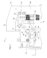
- Fig. 1
- is a side view of a coupling assembly embodying the invention,
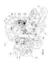
- Fig. 2
- is a perspective view of the coupling assembly of
Fig. 1 , - Fig. 3
- is a perspective view of a implement coupler portion of the coupling assembly of
Fig. 1 , - Fig. 4
- is a sectional view the coupling assembly of
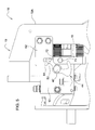
Fig. 2 , - Fig. 5
- is a side view of the coupling assembly of
Fig. 1 in an initial coupling condition, - Fig. 6
- is a side view of the coupling assembly of
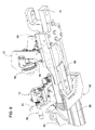
Fig. 1 in a fully coupled condition, - Fig. 7
- is a perspective view of the coupling assembly of
Fig. 1 coupled to a pickup hitch, and - Fig. 8
- is another perspective view of the coupling assembly of
Fig. 1 coupled to a pickup hitch. - Referring to
Figs. 1 to 4 , acoupling assembly 10 is provided for coupling a towed implement to a vehicle or prime mover, in the present embodiment to a tractor used for agricultural work. A manifold orhousing member 12 is mounted to aplate 14.Plate 14 is mounted on anouter housing 84 of apickup hitch 80 of the tractor (seeFigs. 7 and8 ). Animplement coupler unit 16 is fixed to atongue 15 of the implement. Theimplement coupler unit 16 includes abase 17 and acoupler frame 19 withcoupler frame arms base 17. - An implement plate or
coupler plate 18 is movably supported on thecoupler frame 19. One or more hydraulic and/orelectric implement couplers 20 are installed in thecoupler plate 18. As best seen inFigs. 2 and4 ,support brackets 22 project inwardly from thecoupler frame arms bracket 22 has abore 24 which receives asupport bolt 26. Eachsupport bolt 26 has a threadedend 28 which is threadably received by a corresponding threadedbore 30 in thecoupler plate 18. Aresilient spring member 32, such as a coil spring, is mounted around eachsupport bolt 26, between thecoupler plate 18 and eachbracket 22. Eachresilient spring member 32 is biased to urge thecoupler plate 18 towards thehousing member 12.Alignment dowels 34 project from thecoupler plate 18 towards thehousing member 12 and are received byalignment bores 36 formed in thehousing member 12. Thehousing member 12 supportstractor couplers 40 which are matingly engagable with theimplement couplers 20. Theimplement coupler unit 16 may be pulled towards thehousing member 12 by a conventional pickup hitch 80 (seeFigs. 7 and8 ). - As best seen in
Fig. 1 , apivot pin 42 projects laterally from a side of thehousing member 12. Alever member 44 is pivotally mounted on thepivot pin 42. Thelever member 44 has ahub 46 which rotatably receives thepivot pin 42, afirst arm 48 projecting away from thehub 46, and asecond arm 50 projecting away from thehub 46. Thelever member 42 also has alatch pin 52 which projects laterally away from an outer end of thefirst arm 48. Thesecond arm 50 includes afirst leg 54 which is joined to thehub 46 and asecond leg 56 which extends away from thefirst leg 54. The first andsecond legs locking recess 58. - Also as best seen in
Fig. 1 , alatch member 60 is fixed, such as by bolts, to the implementcoupler unit 16. Thelatch member 60 has abody 62, alatch finger 64 spaced apart from thebody 62, and aspacer 66 which connects thelatch finger 64 to thebody 62. Thebody 62, thelatch finger 64 and thespacer 66 form aslot 68 therebetween. Thebody 62 forms aslot wall 70 which is spaced apart from thelatch finger 64 and which faces thelatch finger 64. Thebody 62 also forms alatch wall 72 which is joined to theslot wall 70. Alock pin 71 projecting laterally from thecoupler plate 18. - As best seen in
Figs. 1 and2 , astop member 74 is formed by a hydraulic fitting which is attached to thehousing member 12 spaced apart from thepivot pin 42. Thelever member 44 has an uncoupled position wherein gravity moves thefirst arm 48 towards thelatch member 60 and moves thesecond arm 50 into engagement with thestop member 74. - As best seen in
Figs. 3 and4 , a pair ofalignment dowels 34 projects from thecoupler plate 18. Thehousing member 12 includesalignment bores 36 which receive thealignment dowels 34. - As best seen in
Figs. 5 and6 , thelatch wall 72 engages thelatch pin 52 and pivots thelever member 44 and moves thelatch pin 52 into theslot 68 as theimplement coupler unit 16 moves towards thehousing member 12. Also, thesecond arm 50 moves to a locking position wherein thelocking recess 58 receives thelock pin 71 as thelever member 44 is pivoted by thelatch member 60. - Referring to
Figs. 7 and8 , thetractor pickup hitch 80 is mounted at the rear of atractor frame part 82. Thepickup hitch 80 supports thecoupling assembly 10 which includes theplate 14 and theimplement coupler unit 16. Thepickup hitch 80 includes a fixedouter housing 84, a pivotalinner housing 86 and adrawbar 88 which is slidably received in theinner housing 86. Ahitch ball 90 at the end of thedrawbar 88 is received by adownward opening socket 92 which is formed by thebase 17. Thecoupler frame 19 supports an implementPTO coupler member 94 which is releasably engagable with avehicle PTO device 96. - The result is a
coupling assembly 10 which can automatically connect and lock flat face hydraulicquick couplers production pickup hitch 80 without leaving the tractor cab. The hydraulic cylinder of aproduction pickup 80 hitch brings the hydraulic flat facequick couplers coupling assembly 10 automatically mechanically locks the hydraulic flat facequick couplers coupler plate 18 supports the implementcouplers 20 facing ahousing member 12 which is attached to aplate 14 of thepickup hitch 80.Resilient spring members 32 movably hold thecoupler plate 18 to acoupler frame 19 which is fixed to the implement. As the hydraulic cylinder of thepickup hitch 80 pulls thecoupler frame 19 to the tractor, thecoupler plate 18 contacts thehousing member 12. The hydraulic cylinder continues to pull thecoupler frame 19 towards the tractor, compressing theresilient spring members 32 and preventing damage to the hydraulic flat facequick couplers coupling assembly 10 complete the connection of thedrawbar 88, PTO, hydraulic and electrical connections without requiring the operator to leave the cab.
Claims (8)
- A coupling assembly for coupling a towed implement to a vehicle, the coupling assembly (10) comprising a housing member (12) which can be mounted to the vehicle, the housing member (12) supporting at least one vehicle coupler (40); a coupler frame (19) which can be fixedly attached to the implement; and a coupler plate (18) movably coupled to the coupler frame (19), the coupler plate (18) supporting at least one implement coupler (20) for mating engagement with the vehicle coupler (40).
- The coupling assembly according to claim 1, characterized in that the coupler frame (19) supports an implement PTO coupler member (94) which is releasably engagable with a vehicle PTO device (96).
- The coupling assembly according to claim 1 or 2, characterized in that the housing member (12) is engagable with the coupler plate (18).
- The coupling assembly according to at least one of claims 1 to 3, characterized in that a support bracket (22) projects from the coupler frame (19), the support bracket (22) having a bore (24) extending therethrough, a support bolt (26) is slidably received by the support bracket (22), an end of the support bolt (26) is attached to the coupler plate (18), and a resilient spring member (32) is biased to urge the coupler plate (18) towards the housing member (12).
- The coupling assembly according to claim 4, characterized in that the resilient spring member (32) is mounted around the support bolt (26).
- The coupling assembly according to at least one of claims 1 to 3, characterized by further comprising a plurality of support brackets (22) mounted to the coupler frame (19), each of the support brackets (22) having a bore (24) extending therethrough, a plurality of support bolts (26), each of the support bolts (26) being slidably received by a corresponding support bracket (22), an end of each of the support bolts (26) being attached to the coupler plate (18), and a plurality of resilient spring members (32), each of the resilient spring members (32) being biased to urge the coupler plate (18) towards the housing member (12).
- The coupling assembly according to claim 6, characterized in that each of the resilient spring members (32) is mounted around a corresponding one of the support bolts (26).
- The coupling assembly according to at least one of claims 4 to 7, characterized in that each resilient spring member (32) comprises a coil spring.
Applications Claiming Priority (1)
| Application Number | Priority Date | Filing Date | Title |
|---|---|---|---|
| US14/520,692 US9357690B2 (en) | 2014-10-22 | 2014-10-22 | Tractor-implement coupling mechanism |
Publications (2)
| Publication Number | Publication Date |
|---|---|
| EP3012131A2 true EP3012131A2 (en) | 2016-04-27 |
| EP3012131A3 EP3012131A3 (en) | 2016-06-22 |
Family
ID=54266395
Family Applications (1)
| Application Number | Title | Priority Date | Filing Date |
|---|---|---|---|
| EP15188070.5A Withdrawn EP3012131A3 (en) | 2014-10-22 | 2015-10-02 | Coupling assembly for coupling a towed implement to a vehicle |
Country Status (2)
| Country | Link |
|---|---|
| US (1) | US9357690B2 (en) |
| EP (1) | EP3012131A3 (en) |
Cited By (1)
| Publication number | Priority date | Publication date | Assignee | Title |
|---|---|---|---|---|
| IT202000025828A1 (en) * | 2020-10-30 | 2022-04-30 | Faster Srl | PLATE MULTICONNECTION FOR THE AUTOMATIC CONNECTION OF HYDRAULIC LINES |
Families Citing this family (10)
| Publication number | Priority date | Publication date | Assignee | Title |
|---|---|---|---|---|
| MX2019007052A (en) * | 2016-12-22 | 2020-01-27 | Polaris Inc | QUICK SETTING OF POWER SUPPLY (PTO) FOR UTILITY VEHICLE. |
| CN107558518B (en) * | 2017-10-21 | 2023-04-07 | 盐城师范学院 | Mud flat soil leveling device capable of automatically adjusting levelness |
| DE102017126477A1 (en) | 2017-11-10 | 2019-05-16 | Syn Trac Gmbh | clutch plate |
| US10806066B2 (en) | 2018-05-18 | 2020-10-20 | Deere & Company | Implement multi-coupler with breakaway feature |
| CA3103021C (en) | 2018-06-15 | 2023-11-21 | Clark Equipment Company | Hydraulic coupling |
| DE102020110523A1 (en) * | 2020-04-17 | 2021-10-21 | Liebherr-Hydraulikbagger Gmbh | Quick coupling with centering device |
| US20230227113A1 (en) * | 2022-01-18 | 2023-07-20 | Zoomlion Heavy Industry Na, Inc. | Modular Hydraulic Cab And Frame System With A Universal Junction |
| US20250333123A1 (en) * | 2024-04-26 | 2025-10-30 | R.A. Phillips Industries, Inc. | Automatic coupling system |
| EP4670478A1 (en) * | 2024-06-28 | 2025-12-31 | Mark Duffy | PTO/HYDRAULIC COUPLING DEVICE |
| US12351019B1 (en) * | 2024-07-03 | 2025-07-08 | Caterpillar Inc. | Retainer for power take-off assembly |
Family Cites Families (14)
| Publication number | Priority date | Publication date | Assignee | Title |
|---|---|---|---|---|
| US2429761A (en) | 1946-06-17 | 1947-10-28 | Ketel Henry | Pintle hook |
| US4368899A (en) | 1981-03-16 | 1983-01-18 | Kansas State University Research Foundation | Hitch mechanism for tractors and implements |
| US4738463A (en) | 1987-02-24 | 1988-04-19 | Deere & Company | Automatically coupling fluid connector for a hitch |
| US4763743A (en) | 1987-06-01 | 1988-08-16 | Iowa State University Research Foundation, Inc. | Implement Hitch |
| DE4132889A1 (en) * | 1990-10-05 | 1992-04-09 | Erwin Roeder | Coupling for tractor and ancillary units - has guides in bushes followed by drive coupling engagement |
| US5062321A (en) | 1991-03-11 | 1991-11-05 | General Motors Corporation | Control apparatus for regulating engagement of a fluid operated torque transmitting device |
| SE9600608L (en) * | 1996-02-19 | 1997-02-17 | Kavlugnt Ab | Coupling device for connecting a working tool to a working machine; both mechanical coupling and quick coupling of the hydraulic couplings |
| US7290977B2 (en) * | 2005-03-09 | 2007-11-06 | Clark Equipment Company | Powered coupling of attachment hydraulics |
| US7717189B2 (en) | 2007-04-18 | 2010-05-18 | Kinze Manufacturing, Inc. | Planter with remote hydraulic feed |
| GB201000537D0 (en) | 2010-01-14 | 2010-03-03 | Agco Sa | Tractor implement support linkage |
| US8496070B2 (en) | 2010-09-20 | 2013-07-30 | Deere & Company | Folding hitch lift arm |
| US8770612B2 (en) * | 2012-04-19 | 2014-07-08 | Cnh Industrial America Llc | Automatic tractor hitch system for trailing implements |
| EP2676534B1 (en) | 2012-06-18 | 2015-04-08 | GGP Sweden AB | Fastening means |
| FR2995756B1 (en) | 2012-09-24 | 2015-03-27 | Tracto Lock | DEVICE FOR HITCHING AN AGRICULTURAL TOOL ON A LIFT SYSTEM THREE POINTS OF AN AGRICULTURAL TRACTOR |
-
2014
- 2014-10-22 US US14/520,692 patent/US9357690B2/en active Active
-
2015
- 2015-10-02 EP EP15188070.5A patent/EP3012131A3/en not_active Withdrawn
Non-Patent Citations (1)
| Title |
|---|
| None |
Cited By (1)
| Publication number | Priority date | Publication date | Assignee | Title |
|---|---|---|---|---|
| IT202000025828A1 (en) * | 2020-10-30 | 2022-04-30 | Faster Srl | PLATE MULTICONNECTION FOR THE AUTOMATIC CONNECTION OF HYDRAULIC LINES |
Also Published As
| Publication number | Publication date |
|---|---|
| US9357690B2 (en) | 2016-06-07 |
| US20160113188A1 (en) | 2016-04-28 |
| EP3012131A3 (en) | 2016-06-22 |
Similar Documents
| Publication | Publication Date | Title |
|---|---|---|
| US9357690B2 (en) | Tractor-implement coupling mechanism | |
| EP3011814B1 (en) | Coupling assembly for coupling a towed implement to a prime mover | |
| CN205086621U (en) | Hook is tied to multipurpose trailer | |
| CN111343851B (en) | Docking device with docking socket and docking insert, and method for connecting a vehicle | |
| CA1295870C (en) | Automatically coupling fluid connector for a hitch | |
| US5193623A (en) | Hitching assemblies | |
| US20130020101A1 (en) | Quick connect/disconnect coupling for a stalk stomper | |
| US10156260B1 (en) | Power take-off quick coupler | |
| US2845281A (en) | Hitches | |
| EP3011816A1 (en) | Coupling assembly for connecting an implement propeller shaft to a pto drive of a tractor | |
| US9487928B1 (en) | Receiver plate-coupler plate assembly | |
| US3421780A (en) | Hitching device | |
| EP3012130B1 (en) | Coupler assembly for coupling an implement to a vehicle | |
| EP3012127B1 (en) | Coupler assembly for coupling an implement to a vehicle | |
| US7478823B2 (en) | Drawbar clevis assembly | |
| GB2479890A (en) | Three point coupler | |
| GB2512660A (en) | A quick hitch apparatus | |
| CN203401893U (en) | Tractor hitching device | |
| US9121162B1 (en) | Motor coupler with multiple pick up locations | |
| KR100961612B1 (en) | An apparatus for connecting a farm implements to a tractor | |
| CN204442983U (en) | A kind of tow-bar of tractor | |
| CN201893476U (en) | Automobile wire harness connector | |
| CN217839987U (en) | Quick-release type ground socket | |
| US10736253B2 (en) | Hitch for connecting an implement to a vehicle | |
| CN211995046U (en) | Towing device |
Legal Events
| Date | Code | Title | Description |
|---|---|---|---|
| PUAI | Public reference made under article 153(3) epc to a published international application that has entered the european phase |
Free format text: ORIGINAL CODE: 0009012 |
|
| AK | Designated contracting states |
Kind code of ref document: A2 Designated state(s): AL AT BE BG CH CY CZ DE DK EE ES FI FR GB GR HR HU IE IS IT LI LT LU LV MC MK MT NL NO PL PT RO RS SE SI SK SM TR |
|
| AX | Request for extension of the european patent |
Extension state: BA ME |
|
| PUAL | Search report despatched |
Free format text: ORIGINAL CODE: 0009013 |
|
| AK | Designated contracting states |
Kind code of ref document: A3 Designated state(s): AL AT BE BG CH CY CZ DE DK EE ES FI FR GB GR HR HU IE IS IT LI LT LU LV MC MK MT NL NO PL PT RO RS SE SI SK SM TR |
|
| AX | Request for extension of the european patent |
Extension state: BA ME |
|
| RIC1 | Information provided on ipc code assigned before grant |
Ipc: B60D 1/64 20060101ALI20160519BHEP Ipc: E02F 3/36 20060101ALI20160519BHEP Ipc: A01B 59/06 20060101ALI20160519BHEP Ipc: B60K 17/28 20060101ALI20160519BHEP Ipc: B60D 1/62 20060101AFI20160519BHEP Ipc: B60D 1/00 20060101ALI20160519BHEP Ipc: A01B 59/042 20060101ALI20160519BHEP |
|
| 17P | Request for examination filed |
Effective date: 20161222 |
|
| RBV | Designated contracting states (corrected) |
Designated state(s): AL AT BE BG CH CY CZ DE DK EE ES FI FR GB GR HR HU IE IS IT LI LT LU LV MC MK MT NL NO PL PT RO RS SE SI SK SM TR |
|
| STAA | Information on the status of an ep patent application or granted ep patent |
Free format text: STATUS: THE APPLICATION IS DEEMED TO BE WITHDRAWN |
|
| 18D | Application deemed to be withdrawn |
Effective date: 20161223 |