EP3011892A1 - Endoscope system and endoscope system operation method - Google Patents
Endoscope system and endoscope system operation method Download PDFInfo
- Publication number
- EP3011892A1 EP3011892A1 EP14831416.4A EP14831416A EP3011892A1 EP 3011892 A1 EP3011892 A1 EP 3011892A1 EP 14831416 A EP14831416 A EP 14831416A EP 3011892 A1 EP3011892 A1 EP 3011892A1
- Authority
- EP
- European Patent Office
- Prior art keywords
- light
- colors
- light emission
- light emitting
- emitting elements
- Prior art date
- Legal status (The legal status is an assumption and is not a legal conclusion. Google has not performed a legal analysis and makes no representation as to the accuracy of the status listed.)
- Withdrawn
Links
- 238000000034 method Methods 0.000 title claims abstract description 17
- 239000003086 colorant Substances 0.000 claims abstract description 67
- 238000005286 illumination Methods 0.000 claims abstract description 24
- 230000003287 optical effect Effects 0.000 claims abstract description 17
- 230000008569 process Effects 0.000 claims abstract description 3
- 238000012545 processing Methods 0.000 claims description 20
- 238000004891 communication Methods 0.000 description 13
- 238000010586 diagram Methods 0.000 description 12
- 239000000470 constituent Substances 0.000 description 5
- 238000003780 insertion Methods 0.000 description 5
- 230000037431 insertion Effects 0.000 description 5
- 235000019557 luminance Nutrition 0.000 description 5
- 230000008859 change Effects 0.000 description 4
- 230000006866 deterioration Effects 0.000 description 4
- 230000000694 effects Effects 0.000 description 4
- 230000000630 rising effect Effects 0.000 description 4
- 210000004204 blood vessel Anatomy 0.000 description 3
- 230000006872 improvement Effects 0.000 description 3
- 238000001228 spectrum Methods 0.000 description 3
- 229910052724 xenon Inorganic materials 0.000 description 3
- FHNFHKCVQCLJFQ-UHFFFAOYSA-N xenon atom Chemical compound [Xe] FHNFHKCVQCLJFQ-UHFFFAOYSA-N 0.000 description 3
- 230000008901 benefit Effects 0.000 description 2
- 238000006243 chemical reaction Methods 0.000 description 2
- 238000003384 imaging method Methods 0.000 description 2
- 238000004519 manufacturing process Methods 0.000 description 2
- 239000011159 matrix material Substances 0.000 description 2
- 210000004400 mucous membrane Anatomy 0.000 description 2
- 230000004043 responsiveness Effects 0.000 description 2
- 239000002344 surface layer Substances 0.000 description 2
- 238000012546 transfer Methods 0.000 description 2
- 102000001554 Hemoglobins Human genes 0.000 description 1
- 108010054147 Hemoglobins Proteins 0.000 description 1
- 239000008280 blood Substances 0.000 description 1
- 210000004369 blood Anatomy 0.000 description 1
- 239000003990 capacitor Substances 0.000 description 1
- 238000012937 correction Methods 0.000 description 1
- 238000001514 detection method Methods 0.000 description 1
- 238000009792 diffusion process Methods 0.000 description 1
- 239000000284 extract Substances 0.000 description 1
- 230000006870 function Effects 0.000 description 1
- 230000014759 maintenance of location Effects 0.000 description 1
- 238000012986 modification Methods 0.000 description 1
- 230000004048 modification Effects 0.000 description 1
- 230000035945 sensitivity Effects 0.000 description 1
Images




Classifications
-
- A—HUMAN NECESSITIES
- A61—MEDICAL OR VETERINARY SCIENCE; HYGIENE
- A61B—DIAGNOSIS; SURGERY; IDENTIFICATION
- A61B1/00—Instruments for performing medical examinations of the interior of cavities or tubes of the body by visual or photographical inspection, e.g. endoscopes; Illuminating arrangements therefor
- A61B1/06—Instruments for performing medical examinations of the interior of cavities or tubes of the body by visual or photographical inspection, e.g. endoscopes; Illuminating arrangements therefor with illuminating arrangements
- A61B1/0661—Endoscope light sources
- A61B1/0684—Endoscope light sources using light emitting diodes [LED]
-
- A—HUMAN NECESSITIES
- A61—MEDICAL OR VETERINARY SCIENCE; HYGIENE
- A61B—DIAGNOSIS; SURGERY; IDENTIFICATION
- A61B1/00—Instruments for performing medical examinations of the interior of cavities or tubes of the body by visual or photographical inspection, e.g. endoscopes; Illuminating arrangements therefor
- A61B1/00002—Operational features of endoscopes
- A61B1/00004—Operational features of endoscopes characterised by electronic signal processing
- A61B1/00009—Operational features of endoscopes characterised by electronic signal processing of image signals during a use of endoscope
-
- A—HUMAN NECESSITIES
- A61—MEDICAL OR VETERINARY SCIENCE; HYGIENE
- A61B—DIAGNOSIS; SURGERY; IDENTIFICATION
- A61B1/00—Instruments for performing medical examinations of the interior of cavities or tubes of the body by visual or photographical inspection, e.g. endoscopes; Illuminating arrangements therefor
- A61B1/06—Instruments for performing medical examinations of the interior of cavities or tubes of the body by visual or photographical inspection, e.g. endoscopes; Illuminating arrangements therefor with illuminating arrangements
- A61B1/0638—Instruments for performing medical examinations of the interior of cavities or tubes of the body by visual or photographical inspection, e.g. endoscopes; Illuminating arrangements therefor with illuminating arrangements providing two or more wavelengths
-
- A—HUMAN NECESSITIES
- A61—MEDICAL OR VETERINARY SCIENCE; HYGIENE
- A61B—DIAGNOSIS; SURGERY; IDENTIFICATION
- A61B1/00—Instruments for performing medical examinations of the interior of cavities or tubes of the body by visual or photographical inspection, e.g. endoscopes; Illuminating arrangements therefor
- A61B1/06—Instruments for performing medical examinations of the interior of cavities or tubes of the body by visual or photographical inspection, e.g. endoscopes; Illuminating arrangements therefor with illuminating arrangements
- A61B1/0655—Control therefor
-
- A—HUMAN NECESSITIES
- A61—MEDICAL OR VETERINARY SCIENCE; HYGIENE
- A61B—DIAGNOSIS; SURGERY; IDENTIFICATION
- A61B1/00—Instruments for performing medical examinations of the interior of cavities or tubes of the body by visual or photographical inspection, e.g. endoscopes; Illuminating arrangements therefor
- A61B1/06—Instruments for performing medical examinations of the interior of cavities or tubes of the body by visual or photographical inspection, e.g. endoscopes; Illuminating arrangements therefor with illuminating arrangements
- A61B1/0661—Endoscope light sources
- A61B1/0669—Endoscope light sources at proximal end of an endoscope
-
- G—PHYSICS
- G02—OPTICS
- G02B—OPTICAL ELEMENTS, SYSTEMS OR APPARATUS
- G02B23/00—Telescopes, e.g. binoculars; Periscopes; Instruments for viewing the inside of hollow bodies; Viewfinders; Optical aiming or sighting devices
- G02B23/24—Instruments or systems for viewing the inside of hollow bodies, e.g. fibrescopes
- G02B23/2407—Optical details
- G02B23/2461—Illumination
-
- G—PHYSICS
- G02—OPTICS
- G02B—OPTICAL ELEMENTS, SYSTEMS OR APPARATUS
- G02B27/00—Optical systems or apparatus not provided for by any of the groups G02B1/00 - G02B26/00, G02B30/00
- G02B27/10—Beam splitting or combining systems
- G02B27/1006—Beam splitting or combining systems for splitting or combining different wavelengths
Definitions
- the present invention relates to an endoscope system including a light source device that supplies driving currents to light emitting elements having a plurality of colors and causes the light emitting elements to emit lights and an operation method for the endoscope system.
- a xenon lamp or the like As a light source device for illumination light to be radiated from an endoscope to a subject, a xenon lamp or the like has been used conventionally. However, according to spread of LEDs, a light source device including light emitting elements such as LEDs has been put to practical use taking into account low power consumption and durability.
- a light source device (a frame-sequential system) having such a configuration including the red LED (R-LED), the green LED (G-LED), the blue LED (B-LED), and the violet LED (V-LED) as the light emitting elements is specifically configured, for example, as shown in Fig. 1 related to the present invention.
- Fig. 10 is a timing chart of conventional LED lighting control at a time when normal observation is performed with a maximum light amount.
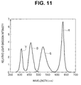
- Fig. 11 is a diagram showing spectra at a time when the conventional LED lighting control shown in Fig. 10 is performed.
- One frame is equally divided into three fields.
- One field is divided into an exposure period and a readout period.
- an LED corresponding to the field is lit at all points in time during the exposure period.
- Pulse width modulation (PWM) is not performed.
- PWM Pulse width modulation
- a maximum rated current Igmax is supplied to the green LED as an electric current (see Fig. 10 ).
- the red LED, the blue LED, and the violet LED are respectively set to current values for enabling a color balance with respect to an emitted light amount of the green LED.
- Light emission luminance (brightness) in such a light source device can be adjusted by, for example, increasing or reducing driving current values supplied to the LEDs of the respective colors or performing the pulse width modulation described above.
- the respective light sources and the image pickup device are simultaneously controlled, respective exposure times, i.e., an exposure time of the image pickup device for lighting only a first light source such as a blue laser light source to pick up an image and an exposure time for lighting only a second light source such as a white light source are respectively individually increased or reduced to be adjusted, and obtained respective picked-up images are combined as observed image data. Therefore, the color tone change in the publication is considered to be performed by a so-called element shutter.
- a light source section 22 includes a first LED 22a for red light emission, a second LED 22b for green light emission, and a third LED 22c for blue light emission and adjustment of driving amounts (e.g., current values in a case of current driving or duty ratios in a case of pulse driving) of first to third LEDs 22a to 22c is performed by a light receiving section 26 that measures emitted light amounts of the first to third LEDs 22a to 22c and an LED driver 21 and that a reference-voltage changing section 21 a calculates first to third reference voltage values V1 to V3 according to an instruction signal related to an emitted light amount setting value set by a user such that a ratio of intensities of red emitted by the first LED 22a, green emitted by the second LED 22b
- driving amounts e.g., current values in a case of current driving or duty ratios in a case of pulse driving
- a light amount of green light is shorter than a target light amount (e.g., a light amount at a time when a xenon lamp is used as a light source). That is, it is desired that light emission luminance (brightness) of a light source device that performs frame-sequential lighting using light emitting elements such as LEDs is improved.
- a driving current supplied to obtain the same light emission intensity sometimes changes because of, for example, temperature and other factors.
- a light emission wavelength and light emission intensity sometimes vary because of aged deterioration. Therefore, it is desirable to also cope with these problems.
- the present invention has been devised in view of the above circumstances and it is an object of the present invention to provide an endoscope system including a light source device of a frame-sequential type, in which light emitting elements are used, capable of increasing a maximum emitted light amount and an operation method for the endoscope system.
- An endoscope system includes: a light source device including light emitting elements of a plurality of colors, a light-emitting-element driving section that supplies driving currents to the light emitting elements of the plurality of colors and causes the light emitting elements to emit lights, and a control section that controls the light-emitting-element driving section; an endoscope that radiates illumination light generated by the light source device on a subject and captures an optical image of the subject; an image pickup device that picks up an optical image of the subject; and a video processor that processes an image picked up by the image pickup device and sets, on the basis of ratios for each of respective colors of respective maximum light emission intensities of the light emitting elements of the plurality of colors and color balance values indicating light amount ratios required of lights of the plurality of colors, respective maximum light emission periods of the light emitting elements of the plurality of colors in one frame period of frame-sequential lighting.
- the control section controls the light-emitting-element driving section such that lights are
- An operation method for an endoscope system is an operation method for an endoscope system comprising: a light-emitting-element driving section of a light source device supplying driving currents to light emitting elements of a plurality of colors and causing the light emitting elements to emit lights; a control section of the light source device controlling the light-emitting-element driving section; an endoscope radiating illumination light generated by the light source device on a subject and capturing an optical image of the subject; an image pickup device picking up an optical image of the subject; a video processor processing an image picked up by the image pickup device and setting, on the basis of ratios for each of the respective colors of respective maximum light emission intensities of the light emitting elements of the plurality of colors and color balance values indicating light amount ratios required of lights of the plurality of colors, respective maximum light emission periods of the light emitting elements of the plurality of colors in one frame period of frame-sequential lighting; and the control section controlling the light-emitting-element driving section such
- Fig. 1 to Fig. 4 show a first embodiment of the present invention.
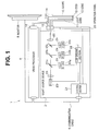
- Fig. 1 is a diagram showing a configuration of an endoscope system.
- An endoscope system 1 includes a scope 2, a light source device 3, a video processor 4, a monitor 5, and a communication cable 6.
- the light source device 3 includes, as light sources, light emitting elements of a plurality of colors, more specifically, a red LED (R-LED) 23r, which is a red (R) light emitting element, a green LED (G-LED) 23g, which is a green (G) light emitting element, a blue LED (B-LED) 23b, which is a blue (B) light emitting element, and a violet LED (V-LED) 23v, which is a violet (V) light emitting element.
- a red LED (R-LED) 23r which is a red (R) light emitting element
- G-LED green LED
- B-LED blue LED
- V-LED violet LED
- Lights emitted from these light emitting elements can form white light.
- white light among respective color bands of red, green, and blue, which are bands of three primary colors forming the white light, light emitted from the red LED 23r forms the red band, light emitted from the green LED 23g forms the green band, and light emitted from the blue LED 23b and narrowband light emitted from the violet LED 23v form the blue band (see Fig. 11 as well).
- the violet LED 23v in the present embodiment is an LED for performing such narrowband light observation (narrow band imaging: NBI (registered trademark)) and emits narrowband light having a wavelength of, for example, 390 to 445 nm.
- NBI registered trademark
- the green LED 23g in the present embodiment emits the narrowband light and also functions as a light emitting element for narrowband.
- the endoscope system 1 in the present embodiment can be set to observation modes including a white light observation mode and a narrowband light observation mode.
- An LED driving section 22 provided in the light source device 3 supplies driving currents respectively to the red LED 23r, the green LED 23g, the blue LED 23b, and the violet LED 23v to drive the LEDs.
- a control section 21 provided in the light source device 3 controls the LED driving section 22 to adjust light emission intensities and light emission periods of respective emitted lights of the red LED 23r, the green LED 23g, the blue LED 23b, and the violet LED 23v.
- the control by the control section 21 is performed on the basis of, for example, information concerning an exposure period and a present brightness value of an object acquired by performing communication with the video processor 4 via the communication cable 6.
- the light source device 3 as optical systems for transmitting illumination light, four collimator lenses 24, three dichroic filters 25a, 25b, and 25c, and one condensing lens 26 are provided.
- the four collimator lenses 24 are disposed on optical paths of respective emitted lights of the red LED 23r, the green LED 23g, the blue LED 23b, and the violet LED 23v.
- the four collimator lenses 24 emit incident light as parallel beams.
- the first dichroic filter 25a transmits red light R emitted from the red LED 23r and reflects green light G emitted from the green LED 23g.
- the second dichroic filter 25b transmits the red light R emitted from the red LED 23r and the green light G emitted from the green LED 23g and reflects blue light B emitted from the blue LED 23b.
- the third dichroic filter 25c transmits the red light R emitted from the red LED 23r, the green light G emitted from the green LED 23g, and the blue light B emitted from the blue LED 23b and reflects the narrowband light V having a violet color emitted from the violet LED 23v.
- the condensing lens 26 condenses a parallel light beams received from the third dichroic filter 25c on an incident end face of a proximal end of a light guide 11 of the scope 2.
- An operation panel 28 provided in the light source device 3 is an operation panel with which the user performs operation for the light source device 3. With the operation panel 28, the user can perform power ON/OFF operation, setting operation for the observation modes such as the white light observation mode and the narrowband light observation mode, and the like.
- An observation mode inputted from the operation panel 28 is transmitted to the video processor 4 via the control section 21 and the communication cable 6. Image processing corresponding to the observation mode is performed.
- the scope 2, which is an endoscope that receives supply of illumination light from such a light source device 3 includes the light guide 11, a lens 12, a CCD 13, a scope-ID storing section 14, a light guide connector 15, and a video connector 16.
- a proximal end of the light guide 11 extends from the light guide connector 15.
- the light guide connector 15 is connected to the light source device 3
- light from the condensing lens 26 is condensed on an incident end face of the proximal end of the light guide 11.
- the light guide 11 is inserted through to a distal end portion in an insertion section of the scope 2.
- the light guide 11 emits illumination light from an emission surface of a distal end.
- the lens 12 for illumination is disposed on an optical path of the illumination light at the distal end of the scope 2. In this way, the illumination light from the light source device 3 transmitted in the light guide 11 is radiated on the subject from the distal end of the insertion section via the lens 12.
- the CCD 13 is a monochrome image pickup device that receives frame-sequential illumination light (on the other hand, if the light source device 3 is a simultaneous illumination type, the CCD 13 is a color image pickup device on which a color filter array or the like is disposed).
- the CCD 13 performs image pickup for converting the optical image of the subject into an electric signal and transmits the electric signal to the video processor 4, to which the video connector 16 is connected, via a signal line.
- the CCD 13 is used as the image pickup device.
- the image pickup device is not limited to this. A CMOS or other image pickup devices may be used.
- the scope-ID storing section 14 is a storing section that stores identification information of the scope 2 in a nonvolatile manner.
- information such as a product number and a manufacturing serial number of the scope 2, time required for readout of the CCD 13, and color balance values indicating light amount ratios required of lights of a plurality of colors are stored.
- the color balance values are RBG light amount ratios RCr, RCg, and RCb needed in the white light observation mode and GV light amount ratios RNg and RNv needed in the narrowband light observation mode by an image pickup system (the CCD 13, the objective lens, etc.) of the scope 2 (i.e., the color balance values are set for each observation mode and, when there is another observation mode, set for the observation mode). That is, photodiodes configured in pixels of the CCD 13, which is the monochrome image pickup device, have different sensitivities depending on bands of received light.
- the RGB light amount ratios RCr, RCg, and RCb are set to values indicating ratios of light amounts that should be respectively received in the red band, the green band, and the blue band in order to generate electric charges color-balanced (in the white light observation mode, white-balanced) after taking into account such various elements.
- the GV light amount ratios RNg and RNv are set to values indicating ratios of light amounts that should be respectively received in the green narrowband and the violet narrow band in order to generate electric charges color-balanced (color-balanced in green and violet) in the narrowband light observation mode.
- the information stored in the scope-ID storing section 14 is read out by the video processor 4 via a signal line.
- the video processor 4 synchronizes the respective color images received from the CCD 13 to generate a color image signal and, after performing image processing such as color balance adjustment, gamma conversion, and color conversion, converts the color image signal into a signal format for display on the monitor 5 and outputs the color image signal to the monitor 5.
- image processing such as color balance adjustment, gamma conversion, and color conversion
- the video processor 4 performs image processing for generating a white light observation image using, for example, a 3x3 matrix of input three components (an R component, a G component, and a (B+V) component) and output three components (an R component, a G component, and a B component).
- the video processor 4 performs image processing for generating a narrow band light observation image using, for example, a 3x2 matrix of input two components (a G component and a V component) and output three components (an R component, a G component, and a B component). That is, in the narrowband light observation mode, even if color components obtained from the CCD 13 is two colors, an image displayed on the monitor 5 is a color display image of three colors.
- the video processor 4 extracts, for example, a luminance signal from the received respective color images and generates information concerning a present brightness value on the basis of the extracted luminance signal.
- the information concerning the present brightness value generated by the video processor 4 in this way is transmitted to the control section 21 of the light source device 3 via the communication cable 6 that connects the video processor 4 and the light source device 3.
- the control section 21 performs, on the basis of the received information concerning the present brightness value, control of light emission intensities of the respective color LEDs as explained above via the LED driving section 22.
- the control section 21 acquires the color balance values stored in the scope-ID storing section 14 via the video processor 4 and performs color balance adjustment of the illumination light, that is, in the white light observation mode, balance adjustment of light emission intensities of the red LED 23r, the green LED 23g, the blue LED 23b, and the violet LED 23v and, in the narrowband light observation mode, balance adjustment of light emission intensities of the green LED 23g and the violet LED 23v.
- the control section 21 causes both of the blue LED 23b and the violet LED 23v to emit lights. By adopting such a light emission form, it is possible to give a margin to an emitted light amount in the blue band.
- Fig. 2 is a timing chart showing light emission timings of the respective color LEDs at a time when frame-sequential illumination of the white light observation mode is performed.
- the CCD 13 alternately performs an operation in an exposure period in which light is received and electric charges are accumulated and an operation in a readout period in which the accumulated electric charges are sequentially read out for each pixel.
- the CCD 13 causes the LED of any one band to emit light and performs exposure in the exposure period and extinguishes all the LEDs and performs readout of an exposed image in the readout period.
- the video processor 4 when starting exposure of one frame, the video processor 4 outputs a frame start signal WSP (see Fig. 2 ) to the light source device 3 and outputs an LED lighting control signal EXP (see Fig. 2 ), which is a light emitting element lighting control signal indicating the exposure periods (i.e., maximum light emission periods of the LEDs), to the light source device 3.
- WSP frame start signal
- EXP LED lighting control signal
- the light source device 3 When a rising edge of the frame start signal WSP is detected, the light source device 3 causes, for example, only the red LED 23r to emit light in an exposure period of a first field in one frame in which the LED lighting control signal EXP is high. Consequently, the CCD 13 receives the red light R from the illuminated subject and performs exposure.
- the light source device 3 detects that the exposure period of the first field ends and extinguishes all the LEDs. After the exposure period ends, the video processor 4 shifts to the readout period and performs, from the CCD 13, readout of an R image obtained by the exposure with the red light R.
- the video processor 4 shifts to an exposure period of a second field and changes the LED lighting control signal EXP to high.
- the light source device 3 causes, for example, only the green LED 23 g to emit light in the exposure period of the second field in which the LED lighting control signal EXP is high. Consequently, the CCD 13 receives the green light G from the illuminated subject and performs exposure.
- the light source device 3 detects that the exposure period of the second field ends and extinguishes all the LEDs. After the exposure period ends, the video processor 4 shifts to the readout period and performs, from the CCD 13, readout of a G image obtained by the exposure with the green light G.
- the video processor 4 shifts to an exposure period of a third field and changes the LED lighting control signal EXP to high.
- the light source device 3 causes, for example, only the blue LED 23b and the violet LED 23v to emit lights. Consequently, the CCD 13 receives the blue light B and the narrowband light V from the illuminated subject and performs exposure.
- the light source device 3 detects that the exposure period of the third field ends and extinguishes all the LEDs. After the exposure period ends, the video processor 4 shifts to the readout period and performs, from the CCD 13, readout of a BV image obtained by the exposure with the blue light B and the narrowband light V.
- the light source device 3 After detecting the rising edge of the frame start signal WSP, the light source device 3 performs light emission in predetermined order, that is, order of R ⁇ G ⁇ (B+V) according to a period in which the LED lighting control signal EXP is high.
- the light source device 3 repeatedly performs the cycle of one frame explained above to acquire images of a plurality of frames.
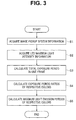
- Fig. 3 is a flowchart for explaining setting processing for exposure periods by the video processor 4.
- the video processor 4 acquires type information of the scope 2 from the scope-ID storing section 14 and acquires information concerning the image pickup system, that is, information such as time required for readout of the CCD 13 (a readout period) and the color balance values in the white light observation mode explained above from the scope-ID storing section 14 (step S1).
- the video processor 4 performs communication with the light source device 3 and acquires information concerning maximum light emission intensities of the respective color LEDs (light emission intensities at a time when maximum rated currents Irmax, Igmax, Ibmax, and Ivmax are supplied respectively to the respective color LEDs 23r, 23g, 23b, and 23v) (step S2).
- the video processor 4 subtracts three fields of a readout period Tf acquired in step S1 from one frame cycle TF and calculates a total exposure period Texp in one frame as indicated by the following Equation 1 (step S3).
- Texp TF ⁇ 3 ⁇ Tf
- the video processor 4 calculates ratios kr, kg, and kb of the exposure periods of the respective colors as indicated by the following Equation 2 on the basis of the RGB light amount ratios RCr, RCg, and RCb, which are the color balance values, acquired in step S1 and the maximum light emission intensity Lr of a red light emitting element section (the red LED 23r), the maximum light emission intensity Lg of a green light emitting element section (the green LED 23g), and maximum light emission intensity Lbv of a blue light emitting element section (a combination of the blue LED 23b and the violet LED 23v) (step S4).
- kr : kg : kb RCr / Lr : RCg / Lg : RCb / Lbv
- a ratio of the light emission intensities of the violet LED 23v and the blue LED 23b is fixed (a fixed ratio for satisfying light intensity of B > light intensity of V).
- the light emission intensity of the blue LED 23b) + (the light emission intensity of the violet LED 23v) at a time when the blue LED 23b reaches the maximum rated current is set as a maximum light emission intensity Lbv of the blue light emitting element section. Therefore, in the white light observation mode, it only has to be considered that the violet LED 23v and the blue LED 23b configure one group of light emitting elements that emit lights in the blue band.
- the video processor 4 calculates, as indicated by the following Equation 3, a maximum light emission period Tr of the red light emitting element section (the red LED 23r), a maximum light emission period Tg of the green light emitting element section (the green LED 23g), and a maximum exposure period Tb of the blue light emitting element section (a combination of the blue LED 23b and the violet LED 23v) corresponding to the exposure periods of the respective colors (step S5) and ends the processing.
- Tr kr / kr + kg + kb ⁇ Texp
- Tg kg / kr + kg + kb ⁇ Texp
- Tb kb / kr + kg + kb ⁇ Texp
- Fig. 2 shows waveforms at a time when, in the maximum light emission periods Tr, Tg, and Tb of the respective color LEDs set in this way, the respective color LEDs are caused to emit lights with maximum light emission intensities in order to obtain maximum emitted light amounts, that is, the respective maximum rated currents Irmax, Igmax, Ibmax, and Ivmax are supplied to the respective color LEDs 23r, 23g, 23b, and 23v.
- the respective color LEDs emit lights at the maximum light emission intensities in all the exposure periods (all the periods in which lights can be emitted excluding the readout periods) and the frame-sequential illumination light is in a color-balanced state. Therefore, light emission abilities of the respective color LEDs can be utilized to maximum.
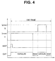
- Fig. 4 is a timing chart for explaining light emission timings of the respective color LEDs at a time of the frame-sequential illumination of the narrowband light observation mode is performed.
- the video processor 4 when starting exposure of one frame, the video processor 4 outputs the frame start signal WSP (see Fig. 4 ) to the light source device 3 and outputs the LED lighting control signal EXP (see Fig. 4 ), which is the light emitting element lighting control signal indicating the exposure period, to the light source device 3.
- WSP frame start signal
- EXP LED lighting control signal
- the light source device 3 When a rising edge of the frame start signal WSP is detected, the light source device 3 causes, for example, only the violet LED 23v to emit light in the exposure period of the first field in one frame in which the LED lighting control signal EXP is high. Consequently, the CCD 13 receives the narrowband light V from the illuminated subject and performs exposure.
- the light source device 3 detects that the exposure period of the first field ends and extinguishes all the LEDs. After the exposure period ends, the video processor 4 shifts to the readout period and performs, from the CCD 13, readout of a V image obtained by the exposure with the narrowband light V.
- the video processor 4 shifts to the exposure period of the second field and changes the LED lighting control signal EXP to high.
- the light source device 3 causes, for example, only the green LED 23g to emit light in the exposure period of the second field in which the LED lighting control signal EXP is high. Consequently, the CCD 13 receives the green light G from the illuminated subject and performs exposure.
- the light source device 3 detects that the exposure period of the second field ends and extinguishes all the LEDs. After the exposure period ends, the video processor 4 shifts to the readout period and performs, from the CCD 13, readout of a G image obtained by the exposure with the green light G.
- the light source device 3 After detecting the rising edge of the frame start signal WSP, the light source device 3 performs light emission in predetermined order, that is, order of V ⁇ G according to a period in which the LED lighting control signal EXP is high.
- the light source device 3 repeatedly performs the cycle of one frame explained above to acquire images of a plurality of frames in the narrowband light observation mode.
- a method of setting the exposure periods for obtaining the maximum emitted light amounts in the narrowband light observation mode is substantially the same as the method in the white light observation mode and is performed by the processing similar to the processing shown in Fig. 3 .
- the video processor 4 acquires, from the scope-ID storing section 14, information concerning the image pickup system, that is, information such as time required for readout of the CCD 13 (a readout period) and the color balance values in the narrowband light observation mode explained above (step S1).
- the video processor 4 performs communication with the light source device 3 and acquires information concerning maximum light emission intensities Lg and Lv of the green LED 23g and the violet LED 23v used in the narrowband light observation (step S2).
- the video processor 4 subtracts two fields of the readout period Tf acquired in step S1 from one frame cycle TNF in the narrowband light observation mode and calculates a total exposure period TNexp in one frame in the narrowband light observation mode as indicated by the following Equation 4 (step S3).
- TNexp TNF ⁇ 2 ⁇ Tf
- the video processor 4 calculates ratios kNg and kNv of the exposure periods of the respective narrow bands as indicated by the following Equation 5 on the basis of the GV light amount ratios RNg and RNv, which are the color balance values, acquired in step S1 and the maximum light emission intensity Lg of the green LED 23g and the maximum light emission intensity Lv of the violet LED 23v acquired in step S2 (step S4).
- kNg : kNv RNg / Lg : RNb / Lv
- the video processor 4 calculates, as indicated by the following Equation 6, a maximum light emission period TNg of the green LED 23g and a maximum light emission period TNv of the violet LED 23v corresponding to the exposure periods of the respective colors in the narrowband light observation mode (step S5) and ends the processing.
- TNg kNg / kNg + kNv ⁇ TNexp
- TNv kNv / kNg + kNv ⁇ TNexp
- Fig. 4 shows waveforms at a time when, in the maximum light emission periods TNg and TNv of the green/violet LEDs in the narrowband light observation mode set in this way, the green/violet LEDs are caused to emit lights with the maximum light emission intensities in order to obtain the maximum emitted light amounts, that is, the respective maximum rated currents Igmax and Ivmax are supplied to the green/violet LEDs 23g and 23v.
- the exposure period of violet is set longer than the exposure period of green.
- the light source device 3 performs automatic light adjustment on the basis of information concerning a present brightness value inputted from the video processor 4.
- the respective color LEDs only have to be subjected to pulse width modulation (PWM) control in the maximum light emission periods of the respective colors, or the driving currents supplied to the respective color LEDs only have to be controlled, or these kinds of control only have to be combined.
- PWM pulse width modulation
- the light source device 3 may transmit end timings of the light emission periods of the respective color LEDs to the video processor 4.
- the video processor 4 notifies the light source device 3 of start timings of the exposure periods of the respective fields.
- the light source device 3 receives the notification and causes the LED of any one of the colors corresponding to a field to emit light.
- an emitted light amount at a present point the emitted light amount only has to be calculated by integrating, with time, for example, light emission intensities associated with driving currents or only have to be calculated by integrating, with time, sensor values of illuminance sensors or the like provided respectively corresponding to the respective color LEDs
- the light source device 3 notifies the video processor 4 of end timing of the light emission period.
- the video processor 4 Upon receiving the end timing of the light emission period, the video processor 4 immediately shifts to the readout period without waiting for an end of the exposure period during the maximum light amount. When the readout period ends, the video processor 4 notifies the light source device 3 of start timings of the exposure period of the next field in the same manner as explained above.
- the CCD 13, which is the image pickup device is disposed at the insertion section distal end portion of the scope 2.
- the configuration may be one in which an optical image is transmitted via a relay optical system or the like and image pickup is performed on a hand side of the scope 2 or in the video processor. Therefore, the image pickup device is not always included in the endoscope.
- the automatic light adjustment is performed by the pulse width modulation control in the maximum light emission periods, if the light source device 3 notifies the video processor 4 of the end timing of the light emission period, it is possible to improve the frame rate.
- Fig. 5 to Fig. 7 show a second embodiment of the present invention.
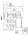
- Fig. 5 is a block diagram showing a configuration of an endoscope system.
- portions same as the portions in the first embodiment are denoted by the same reference numerals and signs and explanation of the portions is omitted. Only differences from the first embodiment are mainly explained.
- the automatic light adjustment is performed by controlling the driving currents supplied to the respective color LEDs in the maximum light emission periods as explained above.
- an illuminance sensor 27r that detects light emission intensity of the red LED 23r
- an illuminance sensor 27g that detects light emission intensity of the green LED 23g
- an illuminance sensor 27b that detects light emission intensity of the blue LED 23b
- the illuminance sensors 27r, 27g, and 27b are disposed in positions (e.g., in vicinities of the respective color LEDs 23r, 23g, and 23b) where leak light not reaching the incident end face of the light guide 11 within light beams emitted from the respective color LEDs 23r, 23g, and 23b is dtected.
- the illuminance sensor 27r, 27g, and 27b output results of the detection of the light intensities to the control section 21.
- the control section 21 includes a sensor-value storing section 31 including an LUT storing section 32, a color-balance-value retaining section 33, a target-brightness setting section 34, and a driving-current setting section 35.
- the sensor-value storing section 31 stores sensor values of results detected by the respective illuminance sensors 27r, 27g, and 27g.
- the LUT storing section 32 is a lookup-table storing section that stores, as a lookup table (LUT), sensor values obtained from the respective illuminance sensors 27r, 27g, and 27b by respectively gradually changing the driving currents Ir, Ig, and Ib of the respective color LEDs 23r, 23g, and 23b from minimum rated currents to maximum rated currents.
- the lookup table is not limited to retention of data stored during manufacturing.
- the lookup table may be updated at appropriate update timing, for example, when a power supply of the endoscope system 1 (more limitedly, the light source device 3) is turned on or color balance values set in the color-balance-value retaining section 33 are changed.
- the LUT storing section 32 is configured as a rewritable storing section. Consequently, it is possible to improve a color balance and accuracy of light adjustment at any point in time.
- the color-balance-value retaining section 33 stores and retains color balance values read out from the scope-ID storing section 14 by the video processor 4.
- the target-brightness setting section 34 retains a brightness value set as a target that information concerning a present brightness value generated and outputted by the video processor 4 should reach.
- the driving-current setting section 35 performs automatic light adjustment for setting driving currents of the light emitting elements of the plurality of colors on the basis of the color balance values read out from the color-balance-value retaining section 33, the target brightness value read out from the target-brightness setting section 34, the present brightness value received from the video processor 4, and a reference result of the lookup table stored in the LUT storing section 32 of the sensor-value storing section 31 such that the present brightness value reaches the target brightness value and light amount ratios of the lights of the plurality of colors are light amount ratios indicated by the color balance values.
- Fig. 7 is a flowchart for explaining processing of the automatic light adjustment in which the color balance is maintained.
- the driving-current setting section 35 acquires CBr and CBb as the color balance values from the color-balance-value retaining section 33 (step S11).
- the driving-current setting section 35 acquires a target brightness value BR0 from the target-brightness setting section 34 (step S12).
- the driving-current setting section 35 acquires a present brightness value BRC from the video processor 4 (step S 13).
- the driving-current setting section 35 determines whether the target brightness value BR0 and the present brightness value BRC are equal (step S14).
- the driving-current setting section 35 acquires a present sensor value Sg of the illuminance sensor 27g for G via the sensor-value storing section 31 (step S15).
- the driving-current setting section 35 calculates, referring to the lookup table in the LUT storing section 32, a driving current Ig to be supplied to the green LED 23g with which a sensor value of Sg ⁇ (BR0/BRC) is obtained (step S16).
- the calculated driving current Ig is 10 (see Fig. 6 ).
- the sensor value Sr is 80.
- the sensor value Sb is 130.
- the respective driving currents Ig, Ir, and Ib obtained in steps S 16 to S 18 are respectively supplied to the respective color LEDs 23r, 23g, and 23b to cause the color LEDs 23r, 23g, and 23b to emit lights (step S19).
- the driving-current setting section 35 acquires the present brightness value BRC based on new driving currents and repeatedly performs the processing explained above.
- the driving-current setting section 35 acquires the present sensor values Sr, Sg, and Sb of the respective illuminance sensors 27r, 27g, and 27b via the sensor-value storing section 31 (step S20) and determines whether a color balance is a demanded balance (step S21).
- step S15 the driving-current setting section 35 repeatedly performs the processing explained above.
- the driving-current setting section 35 ends the processing.
- the driving currents to the respective color LEDs during the light adjustment are calculated with reference to the lookup table. Therefore, it is possible to improve responsiveness.
- the driving currents supplied to the other light emitting elements are calculated with reference to the light emitting element with the lowest light emission efficiency (i.e., the green LED 23g). Therefore, it is possible to prevent a situation in which a light amount of the light emitting element with the lowest light emission efficiency is short and a color balance cannot be kept.
- the lookup table is updated at appropriate update timing, even when the driving currents of the respective color LEDs change or variation occurs in the light emission wavelengths and the light emission intensities of the respective color LEDs because of aged deterioration, it is possible to perform appropriate correction according to a latest state.
- Fig. 8 and Fig. 9 show a third embodiment of the present invention.
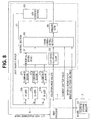
- Fig. 8 is a block diagram showing a configuration of an endoscope system.
- portions same as the portions in the first and second embodiments explained above are denoted by the same reference numerals and signs and explanation of the portions is omitted. Only differences from the first and second embodiments are mainly explained.
- the automatic light adjustment is performed by controlling the driving currents supplied to the respective color LEDs.
- the automatic light adjustment is performed by adjusting light emission periods of the respective color LEDs through pulse width modulation in maximum light emission periods.
- control of exposure times is performed concurrently using an element shutter according to necessary (note that, in the present embodiment, since the element shutter is concurrently used, a total time of exposure periods other than readout periods is not always used for exposure of the CCD 13. Therefore, in the present embodiment, times in which exposure is actually performed in the "exposure periods" are represented as "exposure times").
- a configuration of the light source device 3 in the present embodiment is substantially the same as the configuration shown in Fig. 5 in the second embodiment explained above.
- the LUT storing section 32 is not provided in the sensor-value storing section 31 (however, when light adjustment is performed on the basis of both of the light emission periods and the driving currents of the LEDs, naturally, the LUT storing section 32 may be provided).
- the light source device 3 retains the target brightness value.
- the present brightness value is transmitted from the video processor 4 to the light source device 3.
- a difference between the target brightness value and the present brightness value is transmitted from the video processor 4 to the driving-current setting section 35 of the light source device 3. Therefore, the target-brightness setting section 34 is not provided in the light source device 3 in the second embodiment.
- an element shutter value is transmitted from the video processor 4 to the driving-current setting section 35 of the light source device 3.
- a communication section for performing communication with the video processor 4 is provided in the light source devices in the respective embodiments explained above. However, the communication section is not clearly shown in the drawings. On the other hand, in the present embodiment, it is clearly mentioned that a communication section 36 is provided in the light source device 3, the communication section 36 is connected to the driving-current setting section 35, and an LED light adjustment value is outputted from the communication section 36 to the video processor 4.
- the CCD 13 of the scope 2 is an image pickup device capable of driving the element shutter.
- Fig. 9 is a diagram showing an example for distinguishing, according to exposure times, whether light adjustment is performed by control of light emission periods of LEDs or performed by an element shutter.
- the control of the light emission periods of the LEDs is performed by control of continuous application times of the driving currents supplied to the respective color LEDs in the maximum light emission periods shown in Fig. 2 , that is, pulse width modulation (PWM) control.
- PWM pulse width modulation
- the control of the light emission periods of the LEDs by the pulse width modulation includes not only limitation of the maximum light emission periods but also limitation of minimum light emission periods (TLmin shown in Fig. 9 ). It is inappropriate to cause the LEDs to emit lights and perform the light adjustment for time shorter than the minimum light emission period TLmin.
- the light adjustment is controlled by performing the pulse width modulation.
- the exposure times are less than the minimum light emission time TLmin, exposure corresponding to emitted light amounts of light emission periods shorter than the minimum light emission period TLmin is performed while maintaining the light emission periods of the LEDs at, for example, the minimum light emission period TLmin and by concurrently using the element shutter of the CCD 13 based on the control by the video processor 4.
- the element shutter is control for setting, as a point in time when the element shutter opens, a point in time of start of exposure to a photodiode (e.g., a point in time when new charges start to be accumulated in the photodiode because charges are transferred from the photodiode to a vertical transfer path (in a case of a CCD) or new charges start to be accumulated in the photodiode because application of a reset voltage to the photodiode ends (in a case of a CMOS)) and setting, as a point in time when the element shutter is closed, a point in time of an end of the exposure to the photodiode (e.g., a point in time when charges are transferred from the photodiode to the vertical transfer path (in the case of the CCD) or a point in time when charges are transferred from the photodiode to a capacitor or a memory such as a floating diffusion (in the case of the CMOS)).
- an exposure start is performed according to a light emission start of the LEDs (i.e., an application start of driving currents to the LEDs) and an exposure end is performed at timing for closing the element shutter.
- the video processor 4 since the control of the element shutter is performed by the video processor 4, the video processor 4 can immediately shift to the readout periods. It is possible to easily attain improvement of a frame rate.
- the exposure start and the exposure end are not limited to this. It is also possible to, for example, perform the exposure start according to timing when the element shutter is opened after the light emission of the LEDs is started and perform the exposure end at timing for closing the element shutter before the LEDs end the light emission.
- the driving-current setting section 35 and the video processor 4 of the light source device 3 perform, for each color of the LEDs, for example, control explained below.
- the driving-current setting section 35 receives a difference between a target brightness value and a present brightness value from the video processor 4. If the received difference is in a range in which the LED light adjustment can cope with the difference, the driving-current setting section 35 performs LED light adjustment indicated by a solid line in Fig. 9 and transmits a value of the LED light adjustment to the video processor 4. In this case, the video processor 4 does not need to perform the light adjustment by the element shutter.
- the driving-current setting section 35 sets light emission periods of the LEDs to the minimum light emission period TLmin and transmits light adjustment values of the LEDs to the video processor 4.
- the video processor 4 Upon receiving the LED light adjustment value related to the minimum light emission period TLmin from the light source device 3, the video processor 4 determines whether the difference between the target brightness value and the present brightness value is still present. When determining that the difference is still present even in the minimum light emission period TLmin, the video processor 4 calculates time equivalent to a difference value of the difference and controls, by concurrently using the element shutter, the present brightness value to coincide with the target brightness value.
- the light source device 3 receives the difference between the target brightness value and the present brightness value from the video processor 4. Therefore, the light source device 3 does not need to perform comparison or the like and only has to control an LED light adjustment amount according to a value of the received difference. Therefore, it is possible to attain improvement of responsiveness.
- the present invention may be an operation method for operating the endoscope system including the light source device as explained above or may be a control program for a computer to control the endoscope system including the light source device as explained above, a computer-readable nontransitory recording medium that records the control program, and the like.
- the present invention is not limited to the embodiments per se.
- the constituent elements can be modified and embodied in a range not departing from the spirit of the present invention.
- Aspects of various inventions can be formed by appropriate combinations of the plurality of constituent elements disclosed in the embodiments. For example, several constituent elements can be deleted from all the constituent elements described in the embodiments. Further, the constituent elements described in different embodiments may be combined as appropriate. In this way, it goes without saying that various modifications and applications are possible in a range not departing from the spirit of the invention.
Landscapes
- Health & Medical Sciences (AREA)
- Life Sciences & Earth Sciences (AREA)
- Surgery (AREA)
- Physics & Mathematics (AREA)
- Engineering & Computer Science (AREA)
- Optics & Photonics (AREA)
- Heart & Thoracic Surgery (AREA)
- Animal Behavior & Ethology (AREA)
- Pathology (AREA)
- Radiology & Medical Imaging (AREA)
- Biophysics (AREA)
- Biomedical Technology (AREA)
- Veterinary Medicine (AREA)
- Medical Informatics (AREA)
- Molecular Biology (AREA)
- Nuclear Medicine, Radiotherapy & Molecular Imaging (AREA)
- General Health & Medical Sciences (AREA)
- Public Health (AREA)
- Signal Processing (AREA)
- Microelectronics & Electronic Packaging (AREA)
- Astronomy & Astrophysics (AREA)
- General Physics & Mathematics (AREA)
- Endoscopes (AREA)
- Instruments For Viewing The Inside Of Hollow Bodies (AREA)
Abstract
Description
- The present invention relates to an endoscope system including a light source device that supplies driving currents to light emitting elements having a plurality of colors and causes the light emitting elements to emit lights and an operation method for the endoscope system.
- As a light source device for illumination light to be radiated from an endoscope to a subject, a xenon lamp or the like has been used conventionally. However, according to spread of LEDs, a light source device including light emitting elements such as LEDs has been put to practical use taking into account low power consumption and durability.
- When white light is formed using LEDs, three colors produced by a red LED, a green LED, and a blue LED are enough for forming the white light. However, to also enable narrowband light observation (narrow band imaging: NBI (registered trademark)) that can highlight and observe a blood vessel, a configuration further including a violet LED (V-LED) has been proposed. In the configuration including the violet LED, operation is performed to cause both of the blue LED and the violet LED emit light for blue among red, green, and blue, which are three primary colors forming white light, and give a margin to light intensity of blue light.
- A light source device (a frame-sequential system) having such a configuration including the red LED (R-LED), the green LED (G-LED), the blue LED (B-LED), and the violet LED (V-LED) as the light emitting elements is specifically configured, for example, as shown in
Fig. 1 related to the present invention. -
Fig. 10 is a timing chart of conventional LED lighting control at a time when normal observation is performed with a maximum light amount.Fig. 11 is a diagram showing spectra at a time when the conventional LED lighting control shown inFig. 10 is performed. - One frame is equally divided into three fields. One field is divided into an exposure period and a readout period. When a light amount is maximized, an LED corresponding to the field is lit at all points in time during the exposure period. Pulse width modulation (PWM) is not performed. At this point, since the green LED has low light emission efficiency in a present technique compared with the LEDs of the other colors, a maximum rated current Igmax is supplied to the green LED as an electric current (see
Fig. 10 ). The red LED, the blue LED, and the violet LED are respectively set to current values for enabling a color balance with respect to an emitted light amount of the green LED. That is, current values less than maximum rated currents Irmax, Ibmax, and Ivmax are supplied to the LEDs of the other colors having higher light emission efficiency than the green LED. An example in which relative light emission intensities of lights emitted from the respective color LEDs are shown as spectra isFig. 11 . - Light emission luminance (brightness) in such a light source device can be adjusted by, for example, increasing or reducing driving current values supplied to the LEDs of the respective colors or performing the pulse width modulation described above.
- Concerning color balance adjustment of a light source device, for example, in paragraph [0084] of Japanese Patent Application Laid-Open Publication No.
2011-36361 image pickup device 21 at respective lighting timings are changed to simulatively change a color tone of illumination light. More specifically, the respective light sources and the image pickup device are simultaneously controlled, respective exposure times, i.e., an exposure time of the image pickup device for lighting only a first light source such as a blue laser light source to pick up an image and an exposure time for lighting only a second light source such as a white light source are respectively individually increased or reduced to be adjusted, and obtained respective picked-up images are combined as observed image data. Therefore, the color tone change in the publication is considered to be performed by a so-called element shutter. - Further, as a technique for changing brightness while keeping a color balance, for example, in paragraphs [0020], [0025], and [0027] and
Fig. 2 of Japanese Patent Application Laid-Open Publication No.2010-158415 light source section 22 includes a first LED 22a for red light emission, a second LED 22b for green light emission, and a third LED 22c for blue light emission and adjustment of driving amounts (e.g., current values in a case of current driving or duty ratios in a case of pulse driving) of first to third LEDs 22a to 22c is performed by alight receiving section 26 that measures emitted light amounts of the first to third LEDs 22a to 22c and anLED driver 21 and that a reference-voltage changing section 21 a calculates first to third reference voltage values V1 to V3 according to an instruction signal related to an emitted light amount setting value set by a user such that a ratio of intensities of red emitted by the first LED 22a, green emitted by the second LED 22b, and blue emitted by the third LED 22c is fixed. - On the other hand, concerning adjustment of a light source device involved in aged deterioration of LEDs, for example, in paragraph [0050] of Japanese Patent Application Laid-Open Publication No.
2010-158415 light receiving section 26 to acquire information concerning the emitted light amount and the driving amounts and the emitted light amounts of the first to third LEDs 22a to 22c are accurately adjusted taking into account fluctuation in the emitted light amounts due to the aged deterioration, a temperature change, and the like. - In the conventional LED lighting control shown in
Fig. 10 , there is a problem that a light amount of green light is shorter than a target light amount (e.g., a light amount at a time when a xenon lamp is used as a light source). That is, it is desired that light emission luminance (brightness) of a light source device that performs frame-sequential lighting using light emitting elements such as LEDs is improved. - In the light emitting elements such as the LEDs, a driving current supplied to obtain the same light emission intensity sometimes changes because of, for example, temperature and other factors. A light emission wavelength and light emission intensity sometimes vary because of aged deterioration. Therefore, it is desirable to also cope with these problems.
- The present invention has been devised in view of the above circumstances and it is an object of the present invention to provide an endoscope system including a light source device of a frame-sequential type, in which light emitting elements are used, capable of increasing a maximum emitted light amount and an operation method for the endoscope system.
- An endoscope system according to an aspect of the present invention includes: a light source device including light emitting elements of a plurality of colors, a light-emitting-element driving section that supplies driving currents to the light emitting elements of the plurality of colors and causes the light emitting elements to emit lights, and a control section that controls the light-emitting-element driving section; an endoscope that radiates illumination light generated by the light source device on a subject and captures an optical image of the subject; an image pickup device that picks up an optical image of the subject; and a video processor that processes an image picked up by the image pickup device and sets, on the basis of ratios for each of respective colors of respective maximum light emission intensities of the light emitting elements of the plurality of colors and color balance values indicating light amount ratios required of lights of the plurality of colors, respective maximum light emission periods of the light emitting elements of the plurality of colors in one frame period of frame-sequential lighting. The control section controls the light-emitting-element driving section such that lights are emitted from the light emitting elements of the plurality of colors in a frame-sequential manner in light emission periods in the maximum light emission periods.
- An operation method for an endoscope system according to an aspect of the present invention is an operation method for an endoscope system comprising: a light-emitting-element driving section of a light source device supplying driving currents to light emitting elements of a plurality of colors and causing the light emitting elements to emit lights; a control section of the light source device controlling the light-emitting-element driving section; an endoscope radiating illumination light generated by the light source device on a subject and capturing an optical image of the subject; an image pickup device picking up an optical image of the subject; a video processor processing an image picked up by the image pickup device and setting, on the basis of ratios for each of the respective colors of respective maximum light emission intensities of the light emitting elements of the plurality of colors and color balance values indicating light amount ratios required of lights of the plurality of colors, respective maximum light emission periods of the light emitting elements of the plurality of colors in one frame period of frame-sequential lighting; and the control section controlling the light-emitting-element driving section such that lights are emitted from the light emitting elements of the plurality of colors in a frame-sequential manner in light emission periods in the maximum light emission periods.
-
-
Fig. 1 is a diagram showing a configuration of an endoscope system in a first embodiment of the present invention; -
Fig. 2 is a timing chart showing light emission timings of respective color LEDs at a time when frame-sequential lighting of a white light observation mode is performed in the first embodiment; -
Fig. 3 is a flowchart for explaining setting processing for exposure periods by a video processor in the first embodiment; -
Fig. 4 is a timing chart showing light emission timings of the respective color LEDs at a time when frame-sequential lighting of a narrowband light observation mode is performed in the first embodiment; -
Fig. 5 is a block diagram showing a configuration of an endoscope system in a second embodiment of the present invention; -
Fig. 6 is a diagram showing an example of a lookup table stored in an LUT storing section in the second embodiment; -
Fig. 7 is a flowchart showing processing of automatic light adjustment in which a color balance is maintained in the second embodiment; -
Fig. 8 is a block diagram showing a configuration of an endoscope system in a third embodiment of the present invention; -
Fig. 9 is a diagram showing an example for distinguishing, according to exposure times, whether light adjustment is performed by control of light emission periods of LEDs or performed by an element shutter; -
Fig. 10 is a timing chart of conventional LED lighting control at a time when normal observation is performed with a maximum light amount; and -
Fig. 11 is a diagram showing spectra at a time when the conventional LED lighting control shown inFig. 10 is performed. - Embodiments of the present invention are explained below with reference to the drawings.
-
Fig. 1 to Fig. 4 show a first embodiment of the present invention.Fig. 1 is a diagram showing a configuration of an endoscope system. - An
endoscope system 1 includes ascope 2, alight source device 3, avideo processor 4, amonitor 5, and acommunication cable 6. - The
light source device 3 includes, as light sources, light emitting elements of a plurality of colors, more specifically, a red LED (R-LED) 23r, which is a red (R) light emitting element, a green LED (G-LED) 23g, which is a green (G) light emitting element, a blue LED (B-LED) 23b, which is a blue (B) light emitting element, and a violet LED (V-LED) 23v, which is a violet (V) light emitting element. - Lights emitted from these light emitting elements can form white light. In the present embodiment, among respective color bands of red, green, and blue, which are bands of three primary colors forming the white light, light emitted from the
red LED 23r forms the red band, light emitted from thegreen LED 23g forms the green band, and light emitted from theblue LED 23b and narrowband light emitted from theviolet LED 23v form the blue band (seeFig. 11 as well). - It is known that, when light having a narrow-banded wavelength easily absorbed by hemoglobin in blood is radiated, a blood vessel is highlighted and observed. The
violet LED 23v in the present embodiment is an LED for performing such narrowband light observation (narrow band imaging: NBI (registered trademark)) and emits narrowband light having a wavelength of, for example, 390 to 445 nm. When the narrowband light observation is performed using theviolet LED 23v, it is possible to highlight and observe, for example, a capillary of a mucous membrane surface layer. It is known that, if observation by narrowband light having a wavelength of 530 to 550 nm is performed, it is possible to enhance contrast between thick blood vessel observation in a deep part and the capillary of the mucous membrane surface layer. Therefore, thegreen LED 23g in the present embodiment emits the narrowband light and also functions as a light emitting element for narrowband. - Therefore, the
endoscope system 1 in the present embodiment can be set to observation modes including a white light observation mode and a narrowband light observation mode. - An
LED driving section 22 provided in thelight source device 3 supplies driving currents respectively to thered LED 23r, thegreen LED 23g, theblue LED 23b, and theviolet LED 23v to drive the LEDs. - A
control section 21 provided in thelight source device 3 controls theLED driving section 22 to adjust light emission intensities and light emission periods of respective emitted lights of thered LED 23r, thegreen LED 23g, theblue LED 23b, and theviolet LED 23v. The control by thecontrol section 21 is performed on the basis of, for example, information concerning an exposure period and a present brightness value of an object acquired by performing communication with thevideo processor 4 via thecommunication cable 6. - In the
light source device 3, as optical systems for transmitting illumination light, fourcollimator lenses 24, threedichroic filters lens 26 are provided. - The four
collimator lenses 24 are disposed on optical paths of respective emitted lights of thered LED 23r, thegreen LED 23g, theblue LED 23b, and theviolet LED 23v. The fourcollimator lenses 24 emit incident light as parallel beams. - The first
dichroic filter 25a transmits red light R emitted from thered LED 23r and reflects green light G emitted from thegreen LED 23g. - The second
dichroic filter 25b transmits the red light R emitted from thered LED 23r and the green light G emitted from thegreen LED 23g and reflects blue light B emitted from theblue LED 23b. - The third
dichroic filter 25c transmits the red light R emitted from thered LED 23r, the green light G emitted from thegreen LED 23g, and the blue light B emitted from theblue LED 23b and reflects the narrowband light V having a violet color emitted from theviolet LED 23v. - The condensing
lens 26 condenses a parallel light beams received from the thirddichroic filter 25c on an incident end face of a proximal end of alight guide 11 of thescope 2. - An
operation panel 28 provided in thelight source device 3 is an operation panel with which the user performs operation for thelight source device 3. With theoperation panel 28, the user can perform power ON/OFF operation, setting operation for the observation modes such as the white light observation mode and the narrowband light observation mode, and the like. An observation mode inputted from theoperation panel 28 is transmitted to thevideo processor 4 via thecontrol section 21 and thecommunication cable 6. Image processing corresponding to the observation mode is performed. - The
scope 2, which is an endoscope that receives supply of illumination light from such alight source device 3 includes thelight guide 11, alens 12, aCCD 13, a scope-ID storing section 14, alight guide connector 15, and avideo connector 16. - A proximal end of the
light guide 11 extends from thelight guide connector 15. When thelight guide connector 15 is connected to thelight source device 3, light from the condensinglens 26 is condensed on an incident end face of the proximal end of thelight guide 11. - The
light guide 11 is inserted through to a distal end portion in an insertion section of thescope 2. Thelight guide 11 emits illumination light from an emission surface of a distal end. Thelens 12 for illumination is disposed on an optical path of the illumination light at the distal end of thescope 2. In this way, the illumination light from thelight source device 3 transmitted in thelight guide 11 is radiated on the subject from the distal end of the insertion section via thelens 12. - An optical image of the subject, on which the illumination light is radiated, is captured via a not-shown objective lens disposed at the insertion section distal end of the
scope 2 and formed on theCCD 13, which is an image pickup device. TheCCD 13 is a monochrome image pickup device that receives frame-sequential illumination light (on the other hand, if thelight source device 3 is a simultaneous illumination type, theCCD 13 is a color image pickup device on which a color filter array or the like is disposed). TheCCD 13 performs image pickup for converting the optical image of the subject into an electric signal and transmits the electric signal to thevideo processor 4, to which thevideo connector 16 is connected, via a signal line. Note that theCCD 13 is used as the image pickup device. However, the image pickup device is not limited to this. A CMOS or other image pickup devices may be used. - The scope-
ID storing section 14 is a storing section that stores identification information of thescope 2 in a nonvolatile manner. In the scope-ID storing section 14, information such as a product number and a manufacturing serial number of thescope 2, time required for readout of theCCD 13, and color balance values indicating light amount ratios required of lights of a plurality of colors are stored. The color balance values are RBG light amount ratios RCr, RCg, and RCb needed in the white light observation mode and GV light amount ratios RNg and RNv needed in the narrowband light observation mode by an image pickup system (theCCD 13, the objective lens, etc.) of the scope 2 (i.e., the color balance values are set for each observation mode and, when there is another observation mode, set for the observation mode). That is, photodiodes configured in pixels of theCCD 13, which is the monochrome image pickup device, have different sensitivities depending on bands of received light. Even if light having the same light amount is received, a generated charge amount is different when the received light is in the red band, when the received light is in the green band, and when the received light is in the blue band. An image displayed on themonitor 5 is observed by human eyes. Therefore, the image needs to have a color balance adjusted to the human eyes. Therefore, the RGB light amount ratios RCr, RCg, and RCb are set to values indicating ratios of light amounts that should be respectively received in the red band, the green band, and the blue band in order to generate electric charges color-balanced (in the white light observation mode, white-balanced) after taking into account such various elements. Similarly, the GV light amount ratios RNg and RNv are set to values indicating ratios of light amounts that should be respectively received in the green narrowband and the violet narrow band in order to generate electric charges color-balanced (color-balanced in green and violet) in the narrowband light observation mode. The information stored in the scope-ID storing section 14 is read out by thevideo processor 4 via a signal line. - The
video processor 4 synchronizes the respective color images received from theCCD 13 to generate a color image signal and, after performing image processing such as color balance adjustment, gamma conversion, and color conversion, converts the color image signal into a signal format for display on themonitor 5 and outputs the color image signal to themonitor 5. - In the white light observation mode, the
video processor 4 performs image processing for generating a white light observation image using, for example, a 3x3 matrix of input three components (an R component, a G component, and a (B+V) component) and output three components (an R component, a G component, and a B component). - In the narrowband light observation mode, the
video processor 4 performs image processing for generating a narrow band light observation image using, for example, a 3x2 matrix of input two components (a G component and a V component) and output three components (an R component, a G component, and a B component). That is, in the narrowband light observation mode, even if color components obtained from theCCD 13 is two colors, an image displayed on themonitor 5 is a color display image of three colors. - Further, the
video processor 4 extracts, for example, a luminance signal from the received respective color images and generates information concerning a present brightness value on the basis of the extracted luminance signal. The information concerning the present brightness value generated by thevideo processor 4 in this way is transmitted to thecontrol section 21 of thelight source device 3 via thecommunication cable 6 that connects thevideo processor 4 and thelight source device 3. - The
control section 21 performs, on the basis of the received information concerning the present brightness value, control of light emission intensities of the respective color LEDs as explained above via theLED driving section 22. Thecontrol section 21 acquires the color balance values stored in the scope-ID storing section 14 via thevideo processor 4 and performs color balance adjustment of the illumination light, that is, in the white light observation mode, balance adjustment of light emission intensities of thered LED 23r, thegreen LED 23g, theblue LED 23b, and theviolet LED 23v and, in the narrowband light observation mode, balance adjustment of light emission intensities of thegreen LED 23g and theviolet LED 23v. As explained above, when an image in the blue band in the white light observation mode is acquired, thecontrol section 21 causes both of theblue LED 23b and theviolet LED 23v to emit lights. By adopting such a light emission form, it is possible to give a margin to an emitted light amount in the blue band. -
Fig. 2 is a timing chart showing light emission timings of the respective color LEDs at a time when frame-sequential illumination of the white light observation mode is performed. - The
CCD 13 alternately performs an operation in an exposure period in which light is received and electric charges are accumulated and an operation in a readout period in which the accumulated electric charges are sequentially read out for each pixel. - In a case of the frame-sequential illumination, the
CCD 13 causes the LED of any one band to emit light and performs exposure in the exposure period and extinguishes all the LEDs and performs readout of an exposed image in the readout period. - That is, when starting exposure of one frame, the
video processor 4 outputs a frame start signal WSP (seeFig. 2 ) to thelight source device 3 and outputs an LED lighting control signal EXP (seeFig. 2 ), which is a light emitting element lighting control signal indicating the exposure periods (i.e., maximum light emission periods of the LEDs), to thelight source device 3. - When a rising edge of the frame start signal WSP is detected, the
light source device 3 causes, for example, only thered LED 23r to emit light in an exposure period of a first field in one frame in which the LED lighting control signal EXP is high. Consequently, theCCD 13 receives the red light R from the illuminated subject and performs exposure. - When the LED lighting control signal EXP changes to low, the
light source device 3 detects that the exposure period of the first field ends and extinguishes all the LEDs. After the exposure period ends, thevideo processor 4 shifts to the readout period and performs, from theCCD 13, readout of an R image obtained by the exposure with the red light R. - When the readout period of the first field ends, the
video processor 4 shifts to an exposure period of a second field and changes the LED lighting control signal EXP to high. Thelight source device 3 causes, for example, only thegreen LED 23 g to emit light in the exposure period of the second field in which the LED lighting control signal EXP is high. Consequently, theCCD 13 receives the green light G from the illuminated subject and performs exposure. - When the LED lighting control signal EXP changes to low, the
light source device 3 detects that the exposure period of the second field ends and extinguishes all the LEDs. After the exposure period ends, thevideo processor 4 shifts to the readout period and performs, from theCCD 13, readout of a G image obtained by the exposure with the green light G. - When the readout period of the second field ends, the
video processor 4 shifts to an exposure period of a third field and changes the LED lighting control signal EXP to high. In the exposure period of the third field in which the LED lighting control signal EXP is high, thelight source device 3 causes, for example, only theblue LED 23b and theviolet LED 23v to emit lights. Consequently, theCCD 13 receives the blue light B and the narrowband light V from the illuminated subject and performs exposure. - When the LED lighting control signal EXP changes to low, the
light source device 3 detects that the exposure period of the third field ends and extinguishes all the LEDs. After the exposure period ends, thevideo processor 4 shifts to the readout period and performs, from theCCD 13, readout of a BV image obtained by the exposure with the blue light B and the narrowband light V. - In this way, after detecting the rising edge of the frame start signal WSP, the
light source device 3 performs light emission in predetermined order, that is, order of R→G→(B+V) according to a period in which the LED lighting control signal EXP is high. - The
light source device 3 repeatedly performs the cycle of one frame explained above to acquire images of a plurality of frames. - In the LED lighting control signal EXP outputted to the
light source device 3 by thevideo processor 4, as shown inFig. 2 , all the fields are not the same, that is, one frame is not equally divided into three field periods. Therefore, exposure periods of the respective colors, that is, maximum light emission periods of the respective color LEDs are different for each color. Setting of the maximum light emission periods is performed such that a maximum emitted light amount can be obtained when light emission luminances of the respective color LEDs are maximized (therefore, the maximum emitted light amount of thelight source device 3 increases more than when one frame is equally divided into three to form fields). - The setting of the exposure periods is explained with reference to
Fig. 3. Fig. 3 is a flowchart for explaining setting processing for exposure periods by thevideo processor 4. - When the
scope 2 is connected, thevideo processor 4 acquires type information of thescope 2 from the scope-ID storing section 14 and acquires information concerning the image pickup system, that is, information such as time required for readout of the CCD 13 (a readout period) and the color balance values in the white light observation mode explained above from the scope-ID storing section 14 (step S1). - Further, the
video processor 4 performs communication with thelight source device 3 and acquires information concerning maximum light emission intensities of the respective color LEDs (light emission intensities at a time when maximum rated currents Irmax, Igmax, Ibmax, and Ivmax are supplied respectively to therespective color LEDs - Subsequently, the
video processor 4 subtracts three fields of a readout period Tf acquired in step S1 from one frame cycle TF and calculates a total exposure period Texp in one frame as indicated by the following Equation 1 (step S3).
- The
video processor 4 calculates ratios kr, kg, and kb of the exposure periods of the respective colors as indicated by the followingEquation 2 on the basis of the RGB light amount ratios RCr, RCg, and RCb, which are the color balance values, acquired in step S1 and the maximum light emission intensity Lr of a red light emitting element section (thered LED 23r), the maximum light emission intensity Lg of a green light emitting element section (thegreen LED 23g), and maximum light emission intensity Lbv of a blue light emitting element section (a combination of theblue LED 23b and theviolet LED 23v) (step S4).
- Note that, in the present embodiment, a ratio of the light emission intensities of the
violet LED 23v and theblue LED 23b is fixed (a fixed ratio for satisfying light intensity of B > light intensity of V). (The light emission intensity of theblue LED 23b) + (the light emission intensity of theviolet LED 23v) at a time when theblue LED 23b reaches the maximum rated current is set as a maximum light emission intensity Lbv of the blue light emitting element section. Therefore, in the white light observation mode, it only has to be considered that theviolet LED 23v and theblue LED 23b configure one group of light emitting elements that emit lights in the blue band. - Thereafter, the
video processor 4 calculates, as indicated by the followingEquation 3, a maximum light emission period Tr of the red light emitting element section (thered LED 23r), a maximum light emission period Tg of the green light emitting element section (thegreen LED 23g), and a maximum exposure period Tb of the blue light emitting element section (a combination of theblue LED 23b and theviolet LED 23v) corresponding to the exposure periods of the respective colors (step S5) and ends the processing.
-
Fig. 2 shows waveforms at a time when, in the maximum light emission periods Tr, Tg, and Tb of the respective color LEDs set in this way, the respective color LEDs are caused to emit lights with maximum light emission intensities in order to obtain maximum emitted light amounts, that is, the respective maximum rated currents Irmax, Igmax, Ibmax, and Ivmax are supplied to therespective color LEDs - That is, the respective color LEDs emit lights at the maximum light emission intensities in all the exposure periods (all the periods in which lights can be emitted excluding the readout periods) and the frame-sequential illumination light is in a color-balanced state. Therefore, light emission abilities of the respective color LEDs can be utilized to maximum.
-
Fig. 4 is a timing chart for explaining light emission timings of the respective color LEDs at a time of the frame-sequential illumination of the narrowband light observation mode is performed. - In the narrow band light observation mode as well, when starting exposure of one frame, the
video processor 4 outputs the frame start signal WSP (seeFig. 4 ) to thelight source device 3 and outputs the LED lighting control signal EXP (seeFig. 4 ), which is the light emitting element lighting control signal indicating the exposure period, to thelight source device 3. - When a rising edge of the frame start signal WSP is detected, the
light source device 3 causes, for example, only theviolet LED 23v to emit light in the exposure period of the first field in one frame in which the LED lighting control signal EXP is high. Consequently, theCCD 13 receives the narrowband light V from the illuminated subject and performs exposure. - When the LED lighting control signal EXP changes to low, the
light source device 3 detects that the exposure period of the first field ends and extinguishes all the LEDs. After the exposure period ends, thevideo processor 4 shifts to the readout period and performs, from theCCD 13, readout of a V image obtained by the exposure with the narrowband light V. - When the readout period of the first field ends, the
video processor 4 shifts to the exposure period of the second field and changes the LED lighting control signal EXP to high. Thelight source device 3 causes, for example, only thegreen LED 23g to emit light in the exposure period of the second field in which the LED lighting control signal EXP is high. Consequently, theCCD 13 receives the green light G from the illuminated subject and performs exposure. - When the LED lighting control signal EXP changes to low, the
light source device 3 detects that the exposure period of the second field ends and extinguishes all the LEDs. After the exposure period ends, thevideo processor 4 shifts to the readout period and performs, from theCCD 13, readout of a G image obtained by the exposure with the green light G. - In this way, after detecting the rising edge of the frame start signal WSP, the
light source device 3 performs light emission in predetermined order, that is, order of V→G according to a period in which the LED lighting control signal EXP is high. - The
light source device 3 repeatedly performs the cycle of one frame explained above to acquire images of a plurality of frames in the narrowband light observation mode. - A method of setting the exposure periods for obtaining the maximum emitted light amounts in the narrowband light observation mode is substantially the same as the method in the white light observation mode and is performed by the processing similar to the processing shown in
Fig. 3 . - That is, when being set in the narrowband light observation mode, the
video processor 4 acquires, from the scope-ID storing section 14, information concerning the image pickup system, that is, information such as time required for readout of the CCD 13 (a readout period) and the color balance values in the narrowband light observation mode explained above (step S1). - Further, the
video processor 4 performs communication with thelight source device 3 and acquires information concerning maximum light emission intensities Lg and Lv of thegreen LED 23g and theviolet LED 23v used in the narrowband light observation (step S2). - Subsequently, the
video processor 4 subtracts two fields of the readout period Tf acquired in step S1 from one frame cycle TNF in the narrowband light observation mode and calculates a total exposure period TNexp in one frame in the narrowband light observation mode as indicated by the following Equation 4 (step S3).
- The
video processor 4 calculates ratios kNg and kNv of the exposure periods of the respective narrow bands as indicated by the followingEquation 5 on the basis of the GV light amount ratios RNg and RNv, which are the color balance values, acquired in step S1 and the maximum light emission intensity Lg of thegreen LED 23g and the maximum light emission intensity Lv of theviolet LED 23v acquired in step S2 (step S4).
- Thereafter, the
video processor 4 calculates, as indicated by the followingEquation 6, a maximum light emission period TNg of thegreen LED 23g and a maximum light emission period TNv of theviolet LED 23v corresponding to the exposure periods of the respective colors in the narrowband light observation mode (step S5) and ends the processing.
-
Fig. 4 shows waveforms at a time when, in the maximum light emission periods TNg and TNv of the green/violet LEDs in the narrowband light observation mode set in this way, the green/violet LEDs are caused to emit lights with the maximum light emission intensities in order to obtain the maximum emitted light amounts, that is, the respective maximum rated currents Igmax and Ivmax are supplied to the green/violet LEDs Fig. 4 , the exposure period of violet is set longer than the exposure period of green. - Note that, in
Fig. 2 andFig. 4 , the waveforms of the driving currents supplied to the respective color LEDs when the illumination light is set to the maximum light amount are shown. However, during actual operation, thelight source device 3 performs automatic light adjustment on the basis of information concerning a present brightness value inputted from thevideo processor 4. - In the automatic light adjustment, the respective color LEDs only have to be subjected to pulse width modulation (PWM) control in the maximum light emission periods of the respective colors, or the driving currents supplied to the respective color LEDs only have to be controlled, or these kinds of control only have to be combined.
- Note that when the automatic light adjustment is performed by the pulse width modulation control in the maximum light emission periods, in order to improve a frame rate, the
light source device 3 may transmit end timings of the light emission periods of the respective color LEDs to thevideo processor 4. - That is, the
video processor 4 notifies thelight source device 3 of start timings of the exposure periods of the respective fields. Thelight source device 3 receives the notification and causes the LED of any one of the colors corresponding to a field to emit light. When an emitted light amount at a present point (the emitted light amount only has to be calculated by integrating, with time, for example, light emission intensities associated with driving currents or only have to be calculated by integrating, with time, sensor values of illuminance sensors or the like provided respectively corresponding to the respective color LEDs) reaches a calculated emitted light amount, thelight source device 3 notifies thevideo processor 4 of end timing of the light emission period. - Upon receiving the end timing of the light emission period, the
video processor 4 immediately shifts to the readout period without waiting for an end of the exposure period during the maximum light amount. When the readout period ends, thevideo processor 4 notifies thelight source device 3 of start timings of the exposure period of the next field in the same manner as explained above. - By repeatedly performing such processing, it is possible to improve the frame rate. For example, during near point observation, since a distance from the insertion section distal end of the
scope 2 to the subject is short, a light amount of the illumination light may also be small. Therefore, there is an advantage that the improvement of the frame rate in such a case can be attained. - Note that, in the above explanation, the
CCD 13, which is the image pickup device, is disposed at the insertion section distal end portion of thescope 2. However, without being limited thereto, the configuration may be one in which an optical image is transmitted via a relay optical system or the like and image pickup is performed on a hand side of thescope 2 or in the video processor. Therefore, the image pickup device is not always included in the endoscope. - With the endoscope system and the operation method for the endoscope system in the first embodiment, in the illumination of the frame-sequential type performed using the light emitting elements of the plurality of colors, it is possible to further increase the maximum emitted light amounts than a conventional driving method shown in
Fig. 10 . - Moreover, when the light emission intensities are maximized, in the color-balanced state, light emission is performed at the maximum light emission intensities in all the periods in which the light emitting elements of the respective colors can emit lights. Therefore, it is possible to utilize light emitting abilities of the light emitting elements of the respective colors to maximum. Consequently, it is possible to solve a light amount shortage of the green light at a time when the LEDs are used as the light sources and bring the light amount close to a light amount at a time when a xenon lamp is used as the light source.
- When the automatic light adjustment is performed by the pulse width modulation control in the maximum light emission periods, if the
light source device 3 notifies thevideo processor 4 of the end timing of the light emission period, it is possible to improve the frame rate. -
Fig. 5 to Fig. 7 show a second embodiment of the present invention.Fig. 5 is a block diagram showing a configuration of an endoscope system. - In the second embodiment, portions same as the portions in the first embodiment are denoted by the same reference numerals and signs and explanation of the portions is omitted. Only differences from the first embodiment are mainly explained.
- Note that, in the present embodiment, to simplify explanation, illustration and explanation of the
violet LED 23v and components related to theviolet LED 23v are omitted. However, even when theviolet LED 23v is provided, the following explanation can be applied the same way. - In the present embodiment, the automatic light adjustment is performed by controlling the driving currents supplied to the respective color LEDs in the maximum light emission periods as explained above.
- That is, in the
light source device 3 in the present embodiment, as shown inFig. 5 , as light-intensity detecting sections that detect light emission intensities of light emitting elements of a plurality of colors, anilluminance sensor 27r that detects light emission intensity of thered LED 23r, anilluminance sensor 27g that detects light emission intensity of thegreen LED 23g, and anilluminance sensor 27b that detects light emission intensity of theblue LED 23b are provided. Theilluminance sensors respective color LEDs light guide 11 within light beams emitted from therespective color LEDs illuminance sensor control section 21. - The
control section 21 includes a sensor-value storing section 31 including anLUT storing section 32, a color-balance-value retaining section 33, a target-brightness setting section 34, and a driving-current setting section 35. - The sensor-
value storing section 31 stores sensor values of results detected by therespective illuminance sensors - The
LUT storing section 32 is a lookup-table storing section that stores, as a lookup table (LUT), sensor values obtained from therespective illuminance sensors respective color LEDs value retaining section 33 are changed. In this case, theLUT storing section 32 is configured as a rewritable storing section. Consequently, it is possible to improve a color balance and accuracy of light adjustment at any point in time. -
Fig. 6 is a diagram showing an example of the lookup table stored in theLUT storing section 32. Note that what are described in the lookup table are, among the described items inFig. 6 , concerning columns, respective columns Ig, Sg, Ir, Sr, Ib, and Sb, concerning rows, respective rows excluding rows of Ib = 10.83 and Ir = 13.33, and other fields are descriptions added as references for the explanation. - The color-balance-
value retaining section 33 stores and retains color balance values read out from the scope-ID storing section 14 by thevideo processor 4. - The target-
brightness setting section 34 retains a brightness value set as a target that information concerning a present brightness value generated and outputted by thevideo processor 4 should reach. - The driving-
current setting section 35 performs automatic light adjustment for setting driving currents of the light emitting elements of the plurality of colors on the basis of the color balance values read out from the color-balance-value retaining section 33, the target brightness value read out from the target-brightness setting section 34, the present brightness value received from thevideo processor 4, and a reference result of the lookup table stored in theLUT storing section 32 of the sensor-value storing section 31 such that the present brightness value reaches the target brightness value and light amount ratios of the lights of the plurality of colors are light amount ratios indicated by the color balance values. - The automatic light adjustment in which a color balance is maintained in the present embodiment is explained with reference to
Fig. 5 to Fig. 7 .Fig. 7 is a flowchart for explaining processing of the automatic light adjustment in which the color balance is maintained. - When the processing shown in
Fig. 7 is started, thelight source device 3 acquires the color balance values from the scope-ID storing section 14 via thevideo processor 4 and causes the color-balance-value retaining section 33 to store the color balance values. It is assumed that the color balance values stored by the color-balance-value retaining section 33 are a light amount CBr of red light and a light amount CBb of blue light at a time when a light amount of green light is standardized as 1. If the RGB light amount ratios RCr, RCg, and RCb explained in the first embodiment are used, CBr = RCr/RCg and CBb = RCb/RCg. In the example shown inFig. 6 , CBr = 0.8 and CBb = 1.3. - The driving-
current setting section 35 acquires CBr and CBb as the color balance values from the color-balance-value retaining section 33 (step S11). - Subsequently, the driving-
current setting section 35 acquires a target brightness value BR0 from the target-brightness setting section 34 (step S12). - Further, the driving-
current setting section 35 acquires a present brightness value BRC from the video processor 4 (step S 13). - The driving-
current setting section 35 determines whether the target brightness value BR0 and the present brightness value BRC are equal (step S14). - When it is determined that the target brightness value BR0 and the present brightness value BRC are not equal, the driving-
current setting section 35 acquires a present sensor value Sg of theilluminance sensor 27g for G via the sensor-value storing section 31 (step S15). The driving-current setting section 35 calculates, referring to the lookup table in theLUT storing section 32, a driving current Ig to be supplied to thegreen LED 23g with which a sensor value of Sg×(BR0/BRC) is obtained (step S16). - For example, it is assumed that the calculated driving current Ig is 10 (see
Fig. 6 ). - Subsequently, the driving-
current setting section 35 multiplies the sensor value Sg = 100 corresponding to the calculated driving current Ig = 10 with the color balance value CBr = 0.8 as shown in a fourth column ofFig. 6 and calculates a sensor value Sr of theilluminance sensor 27r for R with which a color balance is obtained with respect to Sg = 100. Here, the sensor value Sr is 80. Further, the driving-current setting section 35 calculates, referring to the lookup table in theLUT storing section 32, a driving current Ir to be supplied to thered LED 23r with which Sr = 80 (step S17). In the example shown inFig. 6 , since a field corresponding to Sr = 80 is absent in the lookup table, the driving-current setting section 35 refers to a field of Sr = 78 and a field of Sr = 84 before and after Sr = 80 and interpolates (e.g., linearly interpolates) a result of the reference to thereby obtain a result of Ir = 13.33. - Subsequently, the driving-
current setting section 35 multiplies the sensor value Sg = 100 with the color balance value CBb = 1.3 as shown in a seventh column ofFig. 6 and calculates a sensor value Sb of theilluminance sensor 27b for B with which a color balance is obtained with respect to Sg = 100. The sensor value Sb is 130. Further the driving-current setting section 35 calculates, referring to the lookup table in theLUT storing section 32, a driving current Ib to be supplied to theblue LED 23b with which Sb = 130 (step S18). In the example shown inFig. 6 , since a field corresponding to Sb = 130 is absent in the lookup table, the driving-current setting section 35 refers to a field of Sb = 120 and a field of Sb = 132 before and after Sb = 130 and interpolates a result of the reference to thereby obtain a result ofIb= 10.83. - In this way, in the present embodiment, the driving currents supplied to the respective color LEDs are calculated with reference to Ig and Sg related to the
green LED 23g. More specifically, the driving current Ir supplied to thered LED 23r is calculated as an electric current with which a sensor value satisfying Sr = CBr×Sg is obtained. The driving current Ib supplied to theblue LED 23b is calculated as an electric current with which a sensor value satisfying Sb = CBb×Sg is obtained. - The respective driving currents Ig, Ir, and Ib obtained in steps S 16 to S 18 are respectively supplied to the
respective color LEDs color LEDs - Returning to step S13 explained above, the driving-
current setting section 35 acquires the present brightness value BRC based on new driving currents and repeatedly performs the processing explained above. - When it is determined in step S 14 that the target brightness value BR0 and the present brightness value BRC are equal, the driving-
current setting section 35 acquires the present sensor values Sr, Sg, and Sb of therespective illuminance sensors - When the color balance is not the demanded color balance yet, returning to step S15, the driving-
current setting section 35 repeatedly performs the processing explained above. - On the other hand, when the color balance is the demanded color balance, light adjustment in which the color balance is maintained has been performed. Therefore, the driving-
current setting section 35 ends the processing. - According to the second embodiment explained above, effects substantially the same as the effects in the first embodiment are attained. The color balance is maintained not only when the color LEDs are caused to emit lights with maximum light amounts but also during light adjustment in which light amounts are changed as appropriate.
- The driving currents to the respective color LEDs during the light adjustment are calculated with reference to the lookup table. Therefore, it is possible to improve responsiveness.
- The driving currents supplied to the other light emitting elements are calculated with reference to the light emitting element with the lowest light emission efficiency (i.e., the
green LED 23g). Therefore, it is possible to prevent a situation in which a light amount of the light emitting element with the lowest light emission efficiency is short and a color balance cannot be kept. - When the lookup table is updated at appropriate update timing, even when the driving currents of the respective color LEDs change or variation occurs in the light emission wavelengths and the light emission intensities of the respective color LEDs because of aged deterioration, it is possible to perform appropriate correction according to a latest state.
-
Fig. 8 andFig. 9 show a third embodiment of the present invention.Fig. 8 is a block diagram showing a configuration of an endoscope system. - In the third embodiment, portions same as the portions in the first and second embodiments explained above are denoted by the same reference numerals and signs and explanation of the portions is omitted. Only differences from the first and second embodiments are mainly explained.
- In the second embodiment explained above, the automatic light adjustment is performed by controlling the driving currents supplied to the respective color LEDs. However, in the present embodiment, the automatic light adjustment is performed by adjusting light emission periods of the respective color LEDs through pulse width modulation in maximum light emission periods. Further, control of exposure times is performed concurrently using an element shutter according to necessary (note that, in the present embodiment, since the element shutter is concurrently used, a total time of exposure periods other than readout periods is not always used for exposure of the
CCD 13. Therefore, in the present embodiment, times in which exposure is actually performed in the "exposure periods" are represented as "exposure times"). - Therefore, a configuration of the
light source device 3 in the present embodiment is substantially the same as the configuration shown inFig. 5 in the second embodiment explained above. However, theLUT storing section 32 is not provided in the sensor-value storing section 31 (however, when light adjustment is performed on the basis of both of the light emission periods and the driving currents of the LEDs, naturally, theLUT storing section 32 may be provided). - In the second embodiment explained above, the
light source device 3 retains the target brightness value. The present brightness value is transmitted from thevideo processor 4 to thelight source device 3. However, in the present embodiment, a difference between the target brightness value and the present brightness value is transmitted from thevideo processor 4 to the driving-current setting section 35 of thelight source device 3. Therefore, the target-brightness setting section 34 is not provided in thelight source device 3 in the second embodiment. - Further, in the present embodiment, an element shutter value is transmitted from the
video processor 4 to the driving-current setting section 35 of thelight source device 3. - A communication section for performing communication with the
video processor 4 is provided in the light source devices in the respective embodiments explained above. However, the communication section is not clearly shown in the drawings. On the other hand, in the present embodiment, it is clearly mentioned that acommunication section 36 is provided in thelight source device 3, thecommunication section 36 is connected to the driving-current setting section 35, and an LED light adjustment value is outputted from thecommunication section 36 to thevideo processor 4. - The
CCD 13 of thescope 2 is an image pickup device capable of driving the element shutter. -
Fig. 9 is a diagram showing an example for distinguishing, according to exposure times, whether light adjustment is performed by control of light emission periods of LEDs or performed by an element shutter. - The control of the light emission periods of the LEDs is performed by control of continuous application times of the driving currents supplied to the respective color LEDs in the maximum light emission periods shown in
Fig. 2 , that is, pulse width modulation (PWM) control. However, the control of the light emission periods of the LEDs by the pulse width modulation includes not only limitation of the maximum light emission periods but also limitation of minimum light emission periods (TLmin shown inFig. 9 ). It is inappropriate to cause the LEDs to emit lights and perform the light adjustment for time shorter than the minimum light emission period TLmin. - Therefore, when the exposure times are the minimum light emission period TLmin or more, the light adjustment is controlled by performing the pulse width modulation. However, when the exposure times are less than the minimum light emission time TLmin, exposure corresponding to emitted light amounts of light emission periods shorter than the minimum light emission period TLmin is performed while maintaining the light emission periods of the LEDs at, for example, the minimum light emission period TLmin and by concurrently using the element shutter of the
CCD 13 based on the control by thevideo processor 4. As it is widely known, the element shutter is control for setting, as a point in time when the element shutter opens, a point in time of start of exposure to a photodiode (e.g., a point in time when new charges start to be accumulated in the photodiode because charges are transferred from the photodiode to a vertical transfer path (in a case of a CCD) or new charges start to be accumulated in the photodiode because application of a reset voltage to the photodiode ends (in a case of a CMOS)) and setting, as a point in time when the element shutter is closed, a point in time of an end of the exposure to the photodiode (e.g., a point in time when charges are transferred from the photodiode to the vertical transfer path (in the case of the CCD) or a point in time when charges are transferred from the photodiode to a capacitor or a memory such as a floating diffusion (in the case of the CMOS)). - Note that, when the exposure times are less than the minimum light emission time TLmin, it is conceivable that, for example, an exposure start is performed according to a light emission start of the LEDs (i.e., an application start of driving currents to the LEDs) and an exposure end is performed at timing for closing the element shutter. In this case, since the control of the element shutter is performed by the
video processor 4, thevideo processor 4 can immediately shift to the readout periods. It is possible to easily attain improvement of a frame rate. However, the exposure start and the exposure end are not limited to this. It is also possible to, for example, perform the exposure start according to timing when the element shutter is opened after the light emission of the LEDs is started and perform the exposure end at timing for closing the element shutter before the LEDs end the light emission. - Therefore, the driving-
current setting section 35 and thevideo processor 4 of thelight source device 3 perform, for each color of the LEDs, for example, control explained below. - The driving-
current setting section 35 receives a difference between a target brightness value and a present brightness value from thevideo processor 4. If the received difference is in a range in which the LED light adjustment can cope with the difference, the driving-current setting section 35 performs LED light adjustment indicated by a solid line inFig. 9 and transmits a value of the LED light adjustment to thevideo processor 4. In this case, thevideo processor 4 does not need to perform the light adjustment by the element shutter. - On the other hand, if the difference between the target brightness value and the present brightness value received from the
video processor 4 exceeds the range in which the LED light adjustment can cope with the difference (i.e., the exposure times are less than the minimum light emission period TLmin), the driving-current setting section 35 sets light emission periods of the LEDs to the minimum light emission period TLmin and transmits light adjustment values of the LEDs to thevideo processor 4. - Upon receiving the LED light adjustment value related to the minimum light emission period TLmin from the
light source device 3, thevideo processor 4 determines whether the difference between the target brightness value and the present brightness value is still present. When determining that the difference is still present even in the minimum light emission period TLmin, thevideo processor 4 calculates time equivalent to a difference value of the difference and controls, by concurrently using the element shutter, the present brightness value to coincide with the target brightness value. - With such processing, only the LED light adjustment or the light adjustment performed concurrently using the element shutter is executed according to length of the exposure times.
- According to the third embodiment explained above, effects substantially the same as the effects in the first and second embodiments explained above are attained. Further, since the element shutter of the image pickup device can perform control with high time resolution, when it is desired to perform exposure same as light emission in time shorter than the minimum light emission period TLmin, it is possible to perform more accurate light adjustment by concurrently using the element shutter.
- The
light source device 3 receives the difference between the target brightness value and the present brightness value from thevideo processor 4. Therefore, thelight source device 3 does not need to perform comparison or the like and only has to control an LED light adjustment amount according to a value of the received difference. Therefore, it is possible to attain improvement of responsiveness. - Note that the endoscope system including the light source device is mainly explained above. However, the present invention may be an operation method for operating the endoscope system including the light source device as explained above or may be a control program for a computer to control the endoscope system including the light source device as explained above, a computer-readable nontransitory recording medium that records the control program, and the like.
- The present invention is not limited to the embodiments per se. In an implementation stage, the constituent elements can be modified and embodied in a range not departing from the spirit of the present invention. Aspects of various inventions can be formed by appropriate combinations of the plurality of constituent elements disclosed in the embodiments. For example, several constituent elements can be deleted from all the constituent elements described in the embodiments. Further, the constituent elements described in different embodiments may be combined as appropriate. In this way, it goes without saying that various modifications and applications are possible in a range not departing from the spirit of the invention.
- This application is based upon and claims the benefit of priority from Japanese Patent Application No.
2013-160749 filed in Japan on August 1, 2013
Claims (12)
- An endoscope system comprising:a light source device including light emitting elements of a plurality of colors, a light-emitting-element driving section that supplies driving currents to the light emitting elements of the plurality of colors and causes the light emitting elements to emit lights, and a control section that controls the light-emitting-element driving section;an endoscope that radiates illumination light generated by the light source device on a subject and captures an optical image of the subject;an image pickup device that picks up an optical image of the subject; anda video processor that processes an image picked up by the image pickup device and sets, on the basis of ratios for each of respective colors of respective maximum light emission intensities of the light emitting elements of the plurality of colors and color balance values indicating light amount ratios required of lights of the plurality of colors, respective maximum light emission periods of the light emitting elements of the plurality of colors in one frame period of frame-sequential lighting, whereinthe control section controls the light-emitting-element driving section such that lights are emitted from the light emitting elements of the plurality of colors in a frame-sequential manner in light emission periods in the maximum light emission periods.
- The endoscope system according to claim 1, wherein the video processor divides the light amount ratios required of the lights of the plurality of colors by the respective maximum light emission intensities of the light emitting elements of the plurality of colors to calculate ratios for each of the respective colors and divides a total exposure period in the one frame period of the frame-sequential lighting at the calculated ratios of for each of the respective colors to thereby calculate the respective maximum light emission periods of the light emitting elements of the plurality of colors.
- The endoscope system according to claim 2, wherein
the endoscope includes an image pickup system including the image pickup device, and
the color balance values are set to values corresponding to the image pickup system of the endoscope. - The endoscope system according to claim 3, wherein
the endoscope further includes a storing section that stores the color balance values, and
the video processor uses the color balance values read out from the storing section of the endoscope. - The endoscope system according to claim 1, wherein the color balance values are decided for each of observation modes.
- The endoscope system according to claim 1, wherein
the video processor calculates a brightness value on the basis of the picked-up image and transmits the brightness value to the light source device,
the light source device performs automatic light adjustment according to pulse width modulation control in the maximum light emission periods on the basis of the brightness value,
the video processor notifies the light source device of start timing of an exposure period,
upon receiving the start timing of the exposure period, the light source device causes the light emitting element of any one of the colors corresponding to a field to emit light for a light emission period by the pulse width modulation and notifies the video processor of end timing of the light emission period, and
upon receiving the end timing of the light emission period, the video processor immediately shifts to a readout period and notifies the light source device of the start timing of the exposure period after an end of the readout period again. - The endoscope system according to claim 1, wherein
the light source device further includes:a light-emission intensity detecting section that detects light emission intensities of the light emitting elements of the plurality of colors; anda lookup-table storing section that stores a lookup table indicating a relation between driving currents supplied to the light emitting elements of the plurality of colors and light emission intensities of lights emitted from the light emitting elements to which the driving currents are supplied,the video processor calculates a brightness value on the basis of the picked-up image and transmits the brightness value to the light source device, andthe light source device performs automatic light adjustment for setting driving currents of the light emitting elements of the plurality of colors on the basis of the color balance values, a target brightness value, a present brightness value received from the video processor, and the lookup table such that the present brightness value reaches the target brightness value and light amount ratios of the lights of the plurality of colors are light amount ratios indicated by the color balance values. - The endoscope system according to claim 7, wherein
the light emitting elements of the plurality of colors include a green light emitting element, and
the light source device multiplies light emission intensity of the green light emitting element detected by the light-emission-intensity detecting section with a value obtained by dividing the target brightness value by the present brightness value to thereby calculate light emission intensity of the green light emitting element for bringing the present brightness value close to the target brightness value, calculates light emission intensities of the light emitting elements of other colors on the basis of the color balance values with reference to the calculated light emission intensity of the green light emitting element, and refers to the lookup table on the basis of the calculated light emission intensities of the light emitting elements of the plurality of colors to thereby set driving currents respectively supplied to the light emitting elements of the plurality of colors. - The endoscope system according to claim 7, wherein the lookup table is created by detecting light emission intensities with the light-emitting-intensity detecting section while changing the driving currents of the light emitting elements of the plurality of colors from a minimum rated current to a maximum rated current.
- The endoscope system according to claim 9, wherein timing when the lookup table is created is at least one of time when a power supply of the endoscope system is turned on and time when the color balance values are changed.
- The endoscope system according to claim 1, wherein
the light source device performs automatic light adjustment according to pulse width modulation control in the maximum light emission periods,
the image pickup device is capable of driving an element shutter, and
the video processor controls the element shutter to reduce an exposure amount when any one of light emission periods of the light emitting elements of the plurality of colors is a minimum light emission period in the pulse width modulation control and when it is necessary to further reduce brightness. - An operation method for an endoscope system comprising:a light-emitting-element driving section of a light source device supplying driving currents to light emitting elements of a plurality of colors and causing the light emitting elements to emit lights;a control section of the light source device controlling the light-emitting-element driving section;an endoscope radiating illumination light generated by the light source device on a subject and capturing an optical image of the subject;an image pickup device picking up an optical image of the subject;a video processor processing an image picked up by the image pickup device and setting, on the basis of ratios for each of the respective colors of respective maximum light emission intensities of the light emitting elements of the plurality of colors and color balance values indicating light amount ratios required of lights of the plurality of colors, respective maximum light emission periods of the light emitting elements of the plurality of colors in one frame period of frame-sequential lighting; andthe control section controlling the light-emitting-element driving section such that lights are emitted from the light emitting elements of the plurality of colors in a frame-sequential manner in light emission periods in the maximum light emission periods.
Applications Claiming Priority (2)
| Application Number | Priority Date | Filing Date | Title |
|---|---|---|---|
| JP2013160749 | 2013-08-01 | ||
| PCT/JP2014/069806 WO2015016172A1 (en) | 2013-08-01 | 2014-07-28 | Endoscope system and endoscope system operation method |
Publications (2)
| Publication Number | Publication Date |
|---|---|
| EP3011892A1 true EP3011892A1 (en) | 2016-04-27 |
| EP3011892A4 EP3011892A4 (en) | 2017-04-26 |
Family
ID=52431705
Family Applications (1)
| Application Number | Title | Priority Date | Filing Date |
|---|---|---|---|
| EP14831416.4A Withdrawn EP3011892A4 (en) | 2013-08-01 | 2014-07-28 | Endoscope system and endoscope system operation method |
Country Status (5)
| Country | Link |
|---|---|
| US (1) | US9826894B2 (en) |
| EP (1) | EP3011892A4 (en) |
| JP (1) | JP5802860B2 (en) |
| CN (1) | CN105407789B (en) |
| WO (1) | WO2015016172A1 (en) |
Cited By (2)
| Publication number | Priority date | Publication date | Assignee | Title |
|---|---|---|---|---|
| EP3184027A4 (en) * | 2015-02-04 | 2018-05-23 | Olympus Corporation | Endoscope device |
| EP3620099A1 (en) * | 2018-09-05 | 2020-03-11 | Fujifilm Corporation | Endoscope system |
Families Citing this family (47)
| Publication number | Priority date | Publication date | Assignee | Title |
|---|---|---|---|---|
| WO2014018936A2 (en) * | 2012-07-26 | 2014-01-30 | Olive Medical Corporation | Continuous video in a light deficient environment |
| EP3119265B1 (en) | 2014-03-21 | 2019-09-11 | DePuy Synthes Products, Inc. | Card edge connector for an imaging sensor |
| JP6355527B2 (en) * | 2014-10-31 | 2018-07-11 | 富士フイルム株式会社 | Endoscope system and operating method thereof |
| JP6522457B2 (en) * | 2015-05-12 | 2019-05-29 | 富士フイルム株式会社 | Endoscope system and method of operating the same |
| CN107529975B (en) * | 2015-05-15 | 2020-07-10 | 索尼公司 | Light source control device, light source control method and imaging system |
| CN107635452B (en) * | 2015-06-02 | 2019-09-13 | 奥林巴斯株式会社 | Special light endoscope device |
| JP6378140B2 (en) * | 2015-07-06 | 2018-08-22 | 富士フイルム株式会社 | Endoscope system and operating method thereof |
| JP2018000228A (en) * | 2016-06-27 | 2018-01-11 | ソニー株式会社 | Illumination device, control method of illumination device, and imaging system |
| JP6654117B2 (en) * | 2016-08-31 | 2020-02-26 | 富士フイルム株式会社 | Endoscope system and method of operating endoscope system |
| WO2018076180A1 (en) * | 2016-10-25 | 2018-05-03 | 深圳迈瑞生物医疗电子股份有限公司 | Medical light-source apparatus |
| EP3417758A1 (en) | 2017-06-19 | 2018-12-26 | Ambu A/S | A method for processing image data using a non-linear scaling model and a medical visual aid system |
| JP6834842B2 (en) * | 2017-08-10 | 2021-02-24 | オムロン株式会社 | Setting support device, image processing system and setting support program |
| EP3673787A4 (en) * | 2017-08-23 | 2020-08-19 | FUJIFILM Corporation | LIGHT SOURCE DEVICE AND ENDOSCOPIC SYSTEM |
| JP6924837B2 (en) * | 2017-09-22 | 2021-08-25 | 富士フイルム株式会社 | Medical image processing system, endoscopy system, diagnostic support device, and medical service support device |
| JP2019080624A (en) | 2017-10-27 | 2019-05-30 | ソニー・オリンパスメディカルソリューションズ株式会社 | Medical light source device and medical endoscope device |
| KR20200104371A (en) | 2017-12-27 | 2020-09-03 | 에티컨, 엘엘씨 | Fluorescence imaging in a light-deficient environment |
| US11147441B2 (en) | 2018-01-16 | 2021-10-19 | Welch Allyn, Inc. | Physical assessment device |
| CN108371535A (en) * | 2018-01-26 | 2018-08-07 | 重庆金山医疗器械有限公司 | Endoscope multi-olored illumination system |
| JP6947918B2 (en) * | 2018-04-05 | 2021-10-13 | オリンパス株式会社 | Light source device for endoscopes and its emission light amount control method |
| JP2019185002A (en) * | 2018-04-11 | 2019-10-24 | ソニー株式会社 | Microscope system and medical light source device |
| CN112118778B (en) * | 2018-05-21 | 2024-10-25 | 奥林巴斯株式会社 | Endoscope system, processor for endoscope, control method for endoscope system, and recording medium |
| US10638921B2 (en) * | 2018-07-20 | 2020-05-05 | Arthrex, Inc. | Medical imaging system |
| JP2022036326A (en) * | 2018-08-29 | 2022-03-08 | オリンパス株式会社 | Endoscope system |
| WO2020100184A1 (en) * | 2018-11-12 | 2020-05-22 | オリンパス株式会社 | Light source device for endoscope, endoscope device, and method for operating light source device for endoscope |
| CN113164026B (en) | 2018-12-04 | 2024-06-11 | 奥林巴斯株式会社 | Light source device and light quantity adjustment method |
| GB2579801B (en) * | 2018-12-13 | 2021-04-14 | Exalos Ag | Superluminescent diode module |
| GB2580956B (en) | 2019-01-31 | 2023-01-25 | Exalos Ag | Amplified Spontaneous Emission Semiconductor Source |
| JP7374598B2 (en) * | 2019-03-15 | 2023-11-07 | ソニー・オリンパスメディカルソリューションズ株式会社 | Light source device, medical observation system, lighting method and program |
| JP7224985B2 (en) * | 2019-03-19 | 2023-02-20 | ソニー・オリンパスメディカルソリューションズ株式会社 | Medical light source device and medical observation system |
| JP7239360B2 (en) * | 2019-03-19 | 2023-03-14 | ソニー・オリンパスメディカルソリューションズ株式会社 | Light source device, medical observation system, illumination method and program |
| CN111343389B (en) * | 2019-05-16 | 2021-09-10 | 杭州海康慧影科技有限公司 | Automatic exposure control method and device |
| US11096565B2 (en) | 2019-06-20 | 2021-08-24 | Cilag Gmbh International | Driving light emissions according to a jitter specification in a hyperspectral, fluorescence, and laser mapping imaging system |
| US11266304B2 (en) | 2019-06-20 | 2022-03-08 | Cilag Gmbh International | Minimizing image sensor input/output in a pulsed hyperspectral imaging system |
| US11389066B2 (en) | 2019-06-20 | 2022-07-19 | Cilag Gmbh International | Noise aware edge enhancement in a pulsed hyperspectral, fluorescence, and laser mapping imaging system |
| US12440085B2 (en) | 2019-06-20 | 2025-10-14 | Cilag Gmbh International | Image synchronization without input clock and data transmission clock in a pulsed laser mapping imaging system |
| US11617541B2 (en) | 2019-06-20 | 2023-04-04 | Cilag Gmbh International | Optical fiber waveguide in an endoscopic system for fluorescence imaging |
| US12126887B2 (en) | 2019-06-20 | 2024-10-22 | Cilag Gmbh International | Hyperspectral and fluorescence imaging with topology laser scanning in a light deficient environment |
| US11012599B2 (en) | 2019-06-20 | 2021-05-18 | Ethicon Llc | Hyperspectral imaging in a light deficient environment |
| US11944273B2 (en) | 2019-06-20 | 2024-04-02 | Cilag Gmbh International | Fluorescence videostroboscopy of vocal cords |
| US10952619B2 (en) | 2019-06-20 | 2021-03-23 | Ethicon Llc | Hyperspectral and fluorescence imaging and topology laser mapping with minimal area monolithic image sensor |
| US11311183B2 (en) | 2019-06-20 | 2022-04-26 | Cilag Gmbh International | Controlling integral energy of a laser pulse in a fluorescence imaging system |
| US11280737B2 (en) | 2019-06-20 | 2022-03-22 | Cilag Gmbh International | Super resolution and color motion artifact correction in a pulsed fluorescence imaging system |
| US11516387B2 (en) | 2019-06-20 | 2022-11-29 | Cilag Gmbh International | Image synchronization without input clock and data transmission clock in a pulsed hyperspectral, fluorescence, and laser mapping imaging system |
| US12013496B2 (en) | 2019-06-20 | 2024-06-18 | Cilag Gmbh International | Noise aware edge enhancement in a pulsed laser mapping imaging system |
| US11589819B2 (en) | 2019-06-20 | 2023-02-28 | Cilag Gmbh International | Offset illumination of a scene using multiple emitters in a laser mapping imaging system |
| US11237270B2 (en) | 2019-06-20 | 2022-02-01 | Cilag Gmbh International | Hyperspectral, fluorescence, and laser mapping imaging with fixed pattern noise cancellation |
| CN115802538A (en) * | 2022-11-09 | 2023-03-14 | 昆山多宾陈列展示股份有限公司 | Light color control method, system, terminal and storage medium |
Family Cites Families (14)
| Publication number | Priority date | Publication date | Assignee | Title |
|---|---|---|---|---|
| US6464633B1 (en) * | 1999-08-23 | 2002-10-15 | Olympus Optical Co., Ltd. | Light source device for endoscope using DMD |
| JP2003093336A (en) | 2001-09-26 | 2003-04-02 | Toshiba Corp | Electronic endoscope device |
| JP2003135393A (en) * | 2001-10-30 | 2003-05-13 | Olympus Optical Co Ltd | Automatic adjusting method for endoscope system |
| KR100961591B1 (en) * | 2004-08-30 | 2010-06-04 | 올림푸스 가부시키가이샤 | Endoscope device |
| JP4772357B2 (en) * | 2005-03-31 | 2011-09-14 | オリンパスメディカルシステムズ株式会社 | Light source device and imaging device |
| JP4868976B2 (en) * | 2006-08-18 | 2012-02-01 | オリンパスメディカルシステムズ株式会社 | Endoscope device |
| JP2010158415A (en) | 2009-01-08 | 2010-07-22 | Hoya Corp | Light source apparatus for endoscope |
| JP5767775B2 (en) * | 2009-07-06 | 2015-08-19 | 富士フイルム株式会社 | Endoscope device |
| JP5401205B2 (en) | 2009-08-10 | 2014-01-29 | 富士フイルム株式会社 | Endoscope device |
| US20110181709A1 (en) * | 2009-12-22 | 2011-07-28 | Integrated Endoscopy, Inc. | Systems and methods for endoscopic imaging with monochromatic detector |
| JP5292379B2 (en) * | 2010-11-09 | 2013-09-18 | 富士フイルム株式会社 | Endoscope device |
| WO2012081336A1 (en) * | 2010-12-13 | 2012-06-21 | オリンパスメディカルシステムズ株式会社 | Medical apparatus |
| JP5498456B2 (en) * | 2011-09-20 | 2014-05-21 | 株式会社東芝 | Electronic endoscope device |
| JP6270465B2 (en) * | 2013-12-25 | 2018-01-31 | オリンパス株式会社 | Optical scanning observation device |
-
2014
- 2014-07-28 CN CN201480030326.7A patent/CN105407789B/en active Active
- 2014-07-28 WO PCT/JP2014/069806 patent/WO2015016172A1/en not_active Ceased
- 2014-07-28 EP EP14831416.4A patent/EP3011892A4/en not_active Withdrawn
- 2014-07-28 JP JP2015506436A patent/JP5802860B2/en active Active
-
2016
- 2016-02-01 US US15/011,882 patent/US9826894B2/en active Active
Cited By (4)
| Publication number | Priority date | Publication date | Assignee | Title |
|---|---|---|---|---|
| EP3184027A4 (en) * | 2015-02-04 | 2018-05-23 | Olympus Corporation | Endoscope device |
| US10610082B2 (en) | 2015-02-04 | 2020-04-07 | Olympus Corporation | Endoscope apparatus |
| EP3620099A1 (en) * | 2018-09-05 | 2020-03-11 | Fujifilm Corporation | Endoscope system |
| US11419488B2 (en) | 2018-09-05 | 2022-08-23 | Fujifilm Corporation | Endoscope system |
Also Published As
| Publication number | Publication date |
|---|---|
| CN105407789B (en) | 2017-07-14 |
| EP3011892A4 (en) | 2017-04-26 |
| US9826894B2 (en) | 2017-11-28 |
| WO2015016172A1 (en) | 2015-02-05 |
| US20160143520A1 (en) | 2016-05-26 |
| JPWO2015016172A1 (en) | 2017-03-02 |
| JP5802860B2 (en) | 2015-11-04 |
| CN105407789A (en) | 2016-03-16 |
Similar Documents
| Publication | Publication Date | Title |
|---|---|---|
| US9826894B2 (en) | Endoscope system with frame-sequential light emission | |
| EP2679137B1 (en) | Endoscope apparatus for controlling light quantity of fluorescence imaging | |
| US9029755B2 (en) | Imaging system with illumination controller to variably control illumination light | |
| EP2698985B1 (en) | Imaging system and imaging method | |
| US10610082B2 (en) | Endoscope apparatus | |
| JP5659315B2 (en) | Endoscope device | |
| EP2544444B1 (en) | Light-emitting apparatus and camera system including the same | |
| WO2014028758A1 (en) | Endoscopic camera illumination system and method | |
| JP5989284B1 (en) | Imaging system and light source device | |
| US10531008B2 (en) | Image pickup system | |
| CN106455960A (en) | Light source device and control method of light source device | |
| CN106163374B (en) | Camera system | |
| JP2012223376A (en) | Control circuit and control method of light-emitting diode for lighting, and electronic endoscope apparatus using the same | |
| WO2025244131A1 (en) | Fluorescent endoscopic apparatus |
Legal Events
| Date | Code | Title | Description |
|---|---|---|---|
| PUAI | Public reference made under article 153(3) epc to a published international application that has entered the european phase |
Free format text: ORIGINAL CODE: 0009012 |
|
| 17P | Request for examination filed |
Effective date: 20160121 |
|
| AK | Designated contracting states |
Kind code of ref document: A1 Designated state(s): AL AT BE BG CH CY CZ DE DK EE ES FI FR GB GR HR HU IE IS IT LI LT LU LV MC MK MT NL NO PL PT RO RS SE SI SK SM TR |
|
| AX | Request for extension of the european patent |
Extension state: BA ME |
|
| RAP1 | Party data changed (applicant data changed or rights of an application transferred) |
Owner name: OLYMPUS CORPORATION |
|
| RAP1 | Party data changed (applicant data changed or rights of an application transferred) |
Owner name: OLYMPUS CORPORATION |
|
| RIN1 | Information on inventor provided before grant (corrected) |
Inventor name: OMORI, KOJI Inventor name: TAKAHASHI, TOMOYA Inventor name: AKIYAMA, DAISUKE Inventor name: SHIROTA, YUTAKA Inventor name: YABE, YUSUKE Inventor name: MASAKI, TAKAHIRO Inventor name: TODA, MASATO |
|
| DAX | Request for extension of the european patent (deleted) | ||
| A4 | Supplementary search report drawn up and despatched |
Effective date: 20170324 |
|
| RIC1 | Information provided on ipc code assigned before grant |
Ipc: A61B 1/00 20060101AFI20170320BHEP Ipc: G02B 27/10 20060101ALN20170320BHEP Ipc: A61B 1/06 20060101ALI20170320BHEP Ipc: G02B 23/24 20060101ALI20170320BHEP |
|
| STAA | Information on the status of an ep patent application or granted ep patent |
Free format text: STATUS: EXAMINATION IS IN PROGRESS |
|
| 17Q | First examination report despatched |
Effective date: 20181114 |
|
| STAA | Information on the status of an ep patent application or granted ep patent |
Free format text: STATUS: THE APPLICATION IS DEEMED TO BE WITHDRAWN |
|
| 18D | Application deemed to be withdrawn |
Effective date: 20190525 |