EP3011876B1 - Part driving structure of coffee machine - Google Patents
Part driving structure of coffee machine Download PDFInfo
- Publication number
- EP3011876B1 EP3011876B1 EP14812913.3A EP14812913A EP3011876B1 EP 3011876 B1 EP3011876 B1 EP 3011876B1 EP 14812913 A EP14812913 A EP 14812913A EP 3011876 B1 EP3011876 B1 EP 3011876B1
- Authority
- EP
- European Patent Office
- Prior art keywords
- pushing board
- transmission
- coffee machine
- guide wheels
- base
- Prior art date
- Legal status (The legal status is an assumption and is not a legal conclusion. Google has not performed a legal analysis and makes no representation as to the accuracy of the status listed.)
- Active
Links
Images




Classifications
-
- A—HUMAN NECESSITIES
- A47—FURNITURE; DOMESTIC ARTICLES OR APPLIANCES; COFFEE MILLS; SPICE MILLS; SUCTION CLEANERS IN GENERAL
- A47J—KITCHEN EQUIPMENT; COFFEE MILLS; SPICE MILLS; APPARATUS FOR MAKING BEVERAGES
- A47J31/00—Apparatus for making beverages
- A47J31/24—Coffee-making apparatus in which hot water is passed through the filter under pressure, i.e. in which the coffee grounds are extracted under pressure
- A47J31/34—Coffee-making apparatus in which hot water is passed through the filter under pressure, i.e. in which the coffee grounds are extracted under pressure with hot water under liquid pressure
- A47J31/36—Coffee-making apparatus in which hot water is passed through the filter under pressure, i.e. in which the coffee grounds are extracted under pressure with hot water under liquid pressure with mechanical pressure-producing means
- A47J31/3604—Coffee-making apparatus in which hot water is passed through the filter under pressure, i.e. in which the coffee grounds are extracted under pressure with hot water under liquid pressure with mechanical pressure-producing means with a mechanism arranged to move the brewing chamber between loading, infusing and ejecting stations
- A47J31/3623—Cartridges being employed
- A47J31/3633—Means to perform transfer from a loading position to an infusing position
Definitions
- the present invention relates to a coffee machine working with coffee capsule, more particularly, to a part driving structure of a coffee machine for driving parts of the coffee machine to move.
- a coffee machine is a machine for preparing of coffee beverage, and conventional components of the coffee machine include a water tank, a heating element and a water pump, etc.; in use a capsule containing coffee powder is brought into the coffee machine, and then in use two parts inside the coffee machine are driven by a driving structure to be closed together so as to form a extraction chamber, at this time the coffee capsule lies in the extraction chamber, and then during the extraction, heated water is pumped by the water pump into the extraction chamber, the water flows through the coffee raw material to be extracted, and then the coffee beverage flows out of a water outlet pipe of the coffee machine into a cup.
- the driving structures for moving two parts to close and open the both parts are mostly based on driving structure of handle-linkage type.
- the Chinese patent for invention No. ZL00812101.X (issue No.: CN1263415Y ) with the title "A Device to Extract Material for Preparing Beverage” discloses a part driving structure of handle-linkage type, comprising a closing rod with two arms and two pulling rods, wherein the both arms of the closing rod are fixed to first pivot journals located on both sides of said second part and can rotate about them, and the pulling rods are fixed to second pivot journals located on both sides of said first part and can rotate about them.
- the ends of the pulling rods and the both arms of the closing rod are securely held together by a third rotatable pivot journal, in order to cooperate with each other so as to close and open the device.
- the Chinese patent for utility model No. ZL200720108105.4 (issue No.: CN201019552Y ) with the title "A Device to Extract Material for Preparing Beverage” also discloses a part driving structure of handle-linkage type, comprising a handle with two arms, a transmission rod, a linkage, a rotary shaft and a transmission shaft, wherein one end of the transmission rod and the both arms of the handle are securely held together by means of the rotary shaft, and the rotary shaft is supported in a base so as to be rotatable relative to the base; one end of the linkage is pivotally connected to a first guide shaft, and the other end of the linkage and the other end of the transmission rod are pivotally connected together by means of the transmission shaft, in order that the handle, the transmission rod and the linkage rod cooperate with each other so as to close or open the first part and the second part.
- CN000101411587A discloses an automatic bag falling mechanism for a coffee machine, which comprises a stand, a first machine member and a second machine member, wherein the first machine member and the second machine member are hermetically closed to form a sealing cavity, and a driving system is also arranged in the stand.
- the prior art automatic bag falling mechanism is characterized in that a push rod movably passes through the rear wall of the second machine member; correspondingly, the rear part in the stand is provided with a barrier piece matched with the push rod, and the barrier piece can move up and down relative to the stand; under the state that the second machine member moves backward relative to the first machine member, the barrier piece blocks the push rod to push the push rod to move toward the direction of ejecting coffee bags relative to the second machine member.
- the prior art structure ejects the coffee bags through the forward movement of the push rod relative to the second machine member, and the barrier piece moves upward relative to the stand during the reset to prevent from being matched with the push rod, thus the coffee bags can be reloaded into a groove cavity of the second machine member for next extraction.
- the technical problem to be solved by the present invention is to provide a part driving structure of a coffee machine with respect to the above-mentioned prior art, in which part driving structure the parts can be actuated to slide only by means of horizontal moving of a pushing board, wherein during operation of this driving structure the pushing board is free of being warped upwards, without additional occupying of spatial height, and it is convenient and effort-saving in operation.
- a part driving structure of a coffee machine comprising a base, a first part provided with a water outlet channel and a second part provided with a water inlet channel; wherein the first part is fixed to the front end of the base, the second part is restrained within the base and can slide back and forth, and there is a capsule inlet provided in the upper portion of the base; characterized in that a pushing board that can slide back and forth relative to the base is provided on the top surface of the base, a vertically disposed driving rod is pivotally connected to the bottom surface of the pushing board, a first transmission rod is pivotally connected to the rear end of the second part, and a second transmission rod is pivotally connected to the rear portion of the base, wherein the lower end of the driving rod, the rear end of the first transmission rod and the front end of the second transmission rod are movably sheathed on one and the same transmission shaft.
- a carriage for guide wheels is fixed to the lower end of the above-mentioned pushing board, the guide wheels are mounted on the carriage for guide wheels, and there is a guide shaft provided in the inner upper portion of the base respectively on the left and the right side, wherein wheel grooves on the guide wheels are in contact with the guide shafts, and the upper end of the driving rod is pivotally connected to the carriage for guide wheels by means of its own pivot journal.
- the above-mentioned carriage for guide wheels is fixed underneath the pushing board by means of screws, and there are two mounting places for guide wheels provided respectively on the left and the right side of the carriage for guide wheels, wherein each of the guide wheels is mounted in one mounting place for guide wheel respectively, and the wheel grooves on the guide wheels on either side are in contact with the guide shaft on the corresponding side.
- the number of guide wheels may be set according to need.
- a first front magnet is inserted in the front end of the above-mentioned carriage for guide wheels, and a second front magnet that corresponds to the first front magnet is inserted in the front portion of the base; a first rear magnet is inserted in the rear end of said carriage for guide wheels, and a second rear magnet that corresponds to the first rear magnet is inserted in the rear portion of the base; and in the state where the second part is actuated by the pushing board forward to be closed together with the first part, the first front magnet and the second front magnet attract together with each other, while in the state where the second part is actuated by the pushing board backward until the first part and the second part are completely opened, the first rear magnet and the second rear magnet attract together with each other.
- warning tone is generated by the attraction of the front and rear magnets, reminding us that the pushing board has been moved in place, which may also enhance touch feeling while moving the pushing board.
- the above-mentioned pushing board can cover said capsule inlet when moving forward to the state where the first part and the second part are closed, while the pushing board opens said capsule inlet when moving backward to the state where the first part and the second part are completely opened.
- the pushing board covers the capsule inlet, which prevents dusts or foreign objects from entering into the interior of the coffee machine and contaminating or damaging internal parts of the coffee machine, so the coffee machine is more secure and hygienic in use.
- the above-mentioned base comprises a frame and a housing
- the frame comprises a front retaining plate, a rear retaining plate and two guide posts supported between the front retaining plate and the rear retaining plate and arranged on the left and the right side parallelly at a distance to each other; wherein the guide posts are movably guided through the housing on the left and the right side so that the housing and the frame can slide relative to each other back and forth; there is a support spring sheathed on the both guide posts respectively, and the support springs are supported between the front retaining plate and the front end face of the housing; the capsule inlet is disposed in the housing, the first part is fixed to the front retaining plate, the second part is sheathed on the corresponding guide posts with its left and right sides and can slide back and forth, and the pushing board is disposed on the upper end face of the housing; a retaining seat having a cavity is fixed to the above-mentioned rear retaining plate, a piston which can slide back and forth is disposed in
- the locking force between the first part and the second part is realized in water hydraulic driving manner; firstly, the second part is driven to be closed together with the first part under the push of the pushing board, then cold water under high pressure enters into the water inlet chamber from the cold water channel, the piston is moved forward relative to the retaining seat; because the retaining seat is fixed to the frame and the position of the housing relative to the casing body of the coffee machine is fixed, the frame can move as a whole backward relative to the housing against the support force of the support springs, the first part also moves backward relative to the housing, and the first part and the second part are gradually clamped against each other under the water pressure to form a closed extraction chamber; since the locking of the first part and the second part is provided not by the support force formed by a first and a second linkages, that is, it is enough that the sliding of the pushing board drives the second part to move near or to get into contact with the first part only by two linkages, during back and forth sliding the pushing board
- the above-mentioned cold water channel is disposed in the piston. Of course, it may also be disposed in the retaining seat.
- mounting block provided in the rear portion inside the above-mentioned housing, wherein the mounting block is sheathed on the guide posts with its left and right sides, the rear end face of the mounting block is in contact with the outer end face of the piston, and the rear end of the second transmission rod is pivotally connected to the mounting block by means of pivot portions on both sides of the second transmission rod.
- the number of the above-mentioned first transmission rods is two, wherein the front ends of the first transmission rods are pivotally connected to the back of the second part by means of first pivot journals, and the rear ends of the first transmission rods are sheathed on the transmission shaft; that the front end of the second transmission rod has two forwardly extending arm portions, and the front ends of the both arm portions are sheathed on the transmission shaft; the lower end of the driving rod is located between the both arm portions, the both first transmission rods are located outside the both arm portions respectively, and there is a jump ring provided on the left and the right end of the transmission shaft respectively so as to axially restrain the first transmission rods, the second transmission rod and the driving rod.
- the second part can be pushed forward more smoothly by providing two first transmission rods, and because the second transmission rod has two arms and the driving rod is located in the middle exactly, the driving rod can smoothly actuate the first transmission rods and the second transmission rod to move.
- the rear portion of the above-mentioned second part has an inner recess
- the front ends of the first transmission rods are pivotally connected inside the inner recess by means of the first pivot journals, in the state where the second part is actuated by the pushing board forward to be closed together with the first part, the lower end faces of the first transmission rods get into contact with the bottom surface of the inner recess, preventing the first transmission rods from further deflecting downward, with the axes of the first transmission rods and the second transmission rod including an obtuse angle, forming a self-locking angle; while the frame moves backward relative to the housing, the pivotable connection end between the first transmission rods and the second transmission rod with respect to each other will not warp upwards under the action of external force, ensuring that the first part and the second part can be pressed together.
- an advantage of the present invention lies in that: the operation of the present driving structure is based on the action of the back and forth lateral sliding of the pushing board, the pushing board is connected with the second part and the base by a specially designed linkage structure, to actuate the second part to slide back and forth relative to the base; because the movement of the pushing board is lateral sliding, unlike the horizontal movement of the second part realized by means of flipping and pulling the handle up and down to drive parts in the traditional coffee machines, the pushing board may not become warped upwards during the operating process, and does not additionally occupy the space height, and it is effort-saving during operation, therefore, the coffee machine adopting such a driving structure can be used normally even if the coffee machine is placed in a cell of which the height space is reduced, and has better adaptability of use.
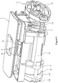
- FIG. 1 to 9 it concerns a preferred embodiment of a part driving structure of a coffee machine according to the present invention.
- the part driving structure of the coffee machine includes a base 1, a first part 2 provided with a water outlet channel 21 and a second part 3 provided with a water inlet channel 31 for feeding hot water, wherein in the water outlet channel 21 there is a first one-way valve assembly 211 provided and in the water inlet channel 31 there is a second one-way valve assembly 311 provided.
- the base in the present embodiment includes two portions: a frame 11 and a housing 12;
- the frame 11 includes a front retaining plate 111, a rear retaining plate 112 and two guide posts 113 supported between the front retaining plate 111 and the rear retaining plate 112 and arranged on the left and the right side parallelly at a distance to each other;
- the housing 12 is a hollow, generally rectangular plastic housing, in the front upper portion of the housing 12 there is a capsule inlet 121 provided for feeding capsules 18, and the guide posts 113 are movably guided through the housing 12 on the left and the right side so that the housing 12 and the frame 11 can slide relative to each other back and forth;
- there is a support spring 114 provided on each of the both guide posts 113 respectively, and the support springs 114 are supported between the front retaining plate 111 and the front end face of the housing 12;
- a retaining seat 15 having a cavity is fixed to the rear retaining plate 112, a piston 16 which can slide back and forth is disposed in the cavity of
- the first part 2 is fixed to the front retaining plate 111, the second part 3 is sheathed on the corresponding guide posts 113 on its left and the right side so as to be slidable back and forth, a receiving chamber for receiving capsules 18 is provided in the second part 3, and the second part 3 is located within the housing 12; a pushing board 4 that can slide back and forth relative to the base 1 is provided on the upper end face of the housing 12, the pushing board 4 is a rectangular plate; the pushing board 4 can cover the capsule inlet 121 when moving forward to the state where the first part 2 and the first part 3 are closed, while the pushing board 4 opens the capsule inlet 121 when moving backward to the state where the first part 2 and the second part 3 are completely opened.
- a vertically disposed driving rod 5 is pivotally connected to the bottom surface of the pushing board 4, the upper end of the driving rod 5 is pivotally connected to a carriage 9 for guide wheels by means of its own pivot journal, first transmission rods 6 are pivotally connected to the rear end of the second part 3, a second transmission rod 7 is pivotally connected to the rear portion of the base 1, the rear end of the second transmission rod 7 is directly or indirectly pivotally connected to the piston 16, there is a mounting block 17 provided in the rear portion inside the housing 12, the mounting block 17 is sheathed on the guide posts 113 on its left and right sides, the rear end face of the mounting block 17 is in contact with the outer end face of the piston 16, the rear end of the second transmission rod 7 is pivotally connected to the mounting block 17 by means of pivot portions 71 on its both sides.
- the lower end of the driving rod 5, the rear ends of the first transmission rods 6 and the front end of the second transmission rod 7 are movably sheathed on one and the same transmission shaft 8.
- first transmission rods 6 There are two first transmission rods 6 provided, wherein the front ends of the first transmission rods 6 are pivotally connected to the back of the second part 3 by means of first pivot journals 61, and the rear ends of the first transmission rods 6 are sheathed on the transmission shaft 8; the front end of the second transmission rod 7 has two forwardly extending arm portions 72, and the front ends of the both arm portions 72 are sheathed on the transmission shaft 8; the lower end of the driving rod 5 is located between the both arm portions 72, the both first transmission rods 6 are located outside the both arm portions 72 respectively, and there is a jump ring provided on the left and the right end of the transmission shaft 8 respectively so as to axially restrain the first transmission rods 6, the second transmission rod 7 and the driving rod 5, wherein the jump rings are not shown in the drawings.
- the rear portion of the second part 3 has an inner recess 32, the front ends of the first transmission rods 6 are pivotally connected within the inner recess 32 by means of the first pivot journals 61; in the state where the second part 3 is actuated by the pushing board 4 forward to be closed together with the first part 2, the lower end faces of the first transmission rods 6 get into contact with the bottom surface of the inner recess 32, preventing the first transmission rods 6 from further deflecting downward, with the axes of the first transmission rods 6 and the second transmission rod 7 including an obtuse angle ⁇ .
- a carriage 9 for guide wheels is fixed to the lower end of the pushing board 7, the carriage 9 for guide wheels is fixed underneath the pushing board 4 by means of screws, and there are two mounting places 92 for the guide wheels provided respectively on the left and the right side of the carriage 9 for the guide wheels, wherein each of the guide wheels 91 is mounted in one mounting place 9 for guide wheel respectively, there is a guide shaft 10 provided in the inner upper portion of the base 1 respectively on the left and the right side, and wheel grooves on the guide wheels 91 on either side are in contact with the guide shaft 10 on the corresponding side.
- a first front magnet 13a is inserted in the front end of the carriage 9 for guide wheels, and a second front magnet 13b that corresponds to the first front magnet 13a is inserted in the middle portion of the housing 12; a first rear magnet 14a is inserted in the rear end of the carriage 9 for guide wheels, and a second rear magnet 14b that corresponds to the first rear magnet 14a is inserted in the rear portion of the housing 12; in the state where the second part 3 is actuated by the pushing board 4 forward to be closed together with the first part 2, the first front magnet 13a and the second front magnet 13b attract together with each other, while in the state where the second part 3 is actuated by the pushing board 4 backward until the first part 2 and the second part 3 are completely opened, the first rear magnet 14a and the second rear magnet 14b attract together with each other.
- Capsule feeding process the capsule 18 is feed from the capsule inlet 121, the pushing board 7 is pushed forward, and the upper end of the driving rod 5 underneath the pushing board 7 deflects forward generally about the transmission shaft 8 as a fulcrum; since the upper end of the driving rod 5 is restrained by the pushing board 7, during deflection of the driving rod 5, the transmission shaft 8 will be actuated to move down relative to the pushing board, so that the transmission shaft 8 will actuate the rear ends of the first transmission rods 6 and the front end of the second transmission rod 7 to move downward, and the first transmission rods 6 and the second transmission rod 7 gradually expand outward and remain horizontal, while because the rear end of the second transmission rod 7 is restrained by the mounting block 18, the second part 3 will be pushed by the second transmission rod 7 forward relative to the first part 2, at the same time the capsule 18 gradually enters into the recess 32 of the second part 3.
- the pushing board 4 covers the capsule inlet 121, and the lower end faces of the first transmission rods 6 get into contact with the bottom surface of the inner recess 32, preventing the first transmission rods 6 from further deflecting downward, with the axes of the first transmission rods 6 and the second transmission rod 7 including an obtuse angle ⁇ .
- the cold water channel 16 is supplied with cold water under high pressure, the cold water under high pressure is pressed into the water inlet chamber 151 and drives the piston 16 to move forward relative to the retaining seat; because when the entire part driving structure is mounted, the retaining seat 15 is fixed to the rear retaining plate 112 of the frame, and the position of the housing 12 relative to the casing body of the coffee machine is fixed, the frame 11 will move as a whole backward relative to the housing 12 against the support force of the support springs 114, the first part 2 also moves backward relative to the housing 12, the first part 2 and the second part 3 are clamped against each other gradually under the water pressure to form a closed extraction chamber, and then coffee extraction process may take place, which process is similar to that of the prior coffee machines.
- the cold water channel 16 is released, the cold water under high pressure in the water inlet chamber 151 is discharged, the entire parts move forward relative to the housing under the action of the support force of the support springs 114, the locking force of the first part 2 and the second part 3 is removed, and then the pushing board 4 is pulled backward, the second part 3 is actuated by the pushing board 4 to move backward relative to the first part 2 under the action of the driving rod 5, the first linkages 6 and the second linkage 7; in the state where the second part 3 is actuated by the pushing board 4 backward until the first part 2 and the second part 3 are completely opened, the first rear magnet 14a and the second rear magnet 14b attract together with each other, the coffee capsule 18 is separated, the pushing board 4 opens the capsules inlet 121; in order to ensure security and hygiene of the coffee machine, when not in use, the pushing board shall be moved forward, and the pushing board 4 covers the capsule inlet 121.
Landscapes
- Engineering & Computer Science (AREA)
- Mechanical Engineering (AREA)
- Food Science & Technology (AREA)
- Apparatus For Making Beverages (AREA)
Description
- The present invention relates to a coffee machine working with coffee capsule, more particularly, to a part driving structure of a coffee machine for driving parts of the coffee machine to move.
- A coffee machine is a machine for preparing of coffee beverage, and conventional components of the coffee machine include a water tank, a heating element and a water pump, etc.; in use a capsule containing coffee powder is brought into the coffee machine, and then in use two parts inside the coffee machine are driven by a driving structure to be closed together so as to form a extraction chamber, at this time the coffee capsule lies in the extraction chamber, and then during the extraction, heated water is pumped by the water pump into the extraction chamber, the water flows through the coffee raw material to be extracted, and then the coffee beverage flows out of a water outlet pipe of the coffee machine into a cup.
- In the prior beverage preparation devices, such as coffee machine, the driving structures for moving two parts to close and open the both parts are mostly based on driving structure of handle-linkage type. For example, the Chinese patent for invention No.
ZL00812101.X CN1263415Y ) with the title "A Device to Extract Material for Preparing Beverage" discloses a part driving structure of handle-linkage type, comprising a closing rod with two arms and two pulling rods, wherein the both arms of the closing rod are fixed to first pivot journals located on both sides of said second part and can rotate about them, and the pulling rods are fixed to second pivot journals located on both sides of said first part and can rotate about them. The ends of the pulling rods and the both arms of the closing rod are securely held together by a third rotatable pivot journal, in order to cooperate with each other so as to close and open the device. - For example, the Chinese patent for utility model No.
ZL200720108105.4 CN201019552Y ) with the title "A Device to Extract Material for Preparing Beverage" also discloses a part driving structure of handle-linkage type, comprising a handle with two arms, a transmission rod, a linkage, a rotary shaft and a transmission shaft, wherein one end of the transmission rod and the both arms of the handle are securely held together by means of the rotary shaft, and the rotary shaft is supported in a base so as to be rotatable relative to the base; one end of the linkage is pivotally connected to a first guide shaft, and the other end of the linkage and the other end of the transmission rod are pivotally connected together by means of the transmission shaft, in order that the handle, the transmission rod and the linkage rod cooperate with each other so as to close or open the first part and the second part.
CN000101411587A - The prior art structure ejects the coffee bags through the forward movement of the push rod relative to the second machine member, and the barrier piece moves upward relative to the stand during the reset to prevent from being matched with the push rod, thus the coffee bags can be reloaded into a groove cavity of the second machine member for next extraction.
- When in use of all the prior part driving structures of handle-linkage type, it is necessary to lift up or to depress the handle; prior to placing coffee capsule, the handle is lifted up to an angle, with the handle being warped upwards and occupying a larger height, so only when the coffee machine of this type is placed in a place with a certain spatial height, it can be used, the requirements for placement space of the coffee machine are high and it is user-unfriendly. In addition, in the prior part driving structures of handle-linkage type, locking of the both parts are achieved by the linkage structure, thus, in order to prevent water leakage during the extraction process, there are higher requirements for locking force of the both parts in the coffee machines, such that after the both parts are closed together, due to the very large locking force between the both parts, a larger force is required to actuate the handle and thus the operation is effort-intensive, if man wants to open the both parts again.
- The technical problem to be solved by the present invention is to provide a part driving structure of a coffee machine with respect to the above-mentioned prior art, in which part driving structure the parts can be actuated to slide only by means of horizontal moving of a pushing board, wherein during operation of this driving structure the pushing board is free of being warped upwards, without additional occupying of spatial height, and it is convenient and effort-saving in operation.
- The present invention solves the above-mentioned technical problem by means of the following technical solution: a part driving structure of a coffee machine, comprising a base, a first part provided with a water outlet channel and a second part provided with a water inlet channel;
wherein the first part is fixed to the front end of the base, the second part is restrained within the base and can slide back and forth, and there is a capsule inlet provided in the upper portion of the base;
characterized in that a pushing board that can slide back and forth relative to the base is provided on the top surface of the base, a vertically disposed driving rod is pivotally connected to the bottom surface of the pushing board, a first transmission rod is pivotally connected to the rear end of the second part, and a second transmission rod is pivotally connected to the rear portion of the base, wherein the lower end of the driving rod, the rear end of the first transmission rod and the front end of the second transmission rod are movably sheathed on one and the same transmission shaft. - In order to make the pushing board slide more smoothly and to save force during pushing, a carriage for guide wheels is fixed to the lower end of the above-mentioned pushing board, the guide wheels are mounted on the carriage for guide wheels, and there is a guide shaft provided in the inner upper portion of the base respectively on the left and the right side, wherein wheel grooves on the guide wheels are in contact with the guide shafts, and the upper end of the driving rod is pivotally connected to the carriage for guide wheels by means of its own pivot journal. By contact limit realized by the guide wheels on the carriage for guide wheels and the guide shafts, the pushing board can be prevented from shaking during sliding, and at the same time because the guide wheels and the guide shafts are in rolling contact during sliding of the pushing board, the pushing board slides more easily.
- The above-mentioned carriage for guide wheels is fixed underneath the pushing board by means of screws, and there are two mounting places for guide wheels provided respectively on the left and the right side of the carriage for guide wheels, wherein each of the guide wheels is mounted in one mounting place for guide wheel respectively, and the wheel grooves on the guide wheels on either side are in contact with the guide shaft on the corresponding side. By the contact limit realized by more than one guide wheel and guide shaft, the pushing board is more effectively prevented from shaking during sliding, and at the same time the pushing board slides more easily. The number of guide wheels may be set according to need.
- A first front magnet is inserted in the front end of the above-mentioned carriage for guide wheels, and a second front magnet that corresponds to the first front magnet is inserted in the front portion of the base; a first rear magnet is inserted in the rear end of said carriage for guide wheels, and a second rear magnet that corresponds to the first rear magnet is inserted in the rear portion of the base; and in the state where the second part is actuated by the pushing board forward to be closed together with the first part, the first front magnet and the second front magnet attract together with each other, while in the state where the second part is actuated by the pushing board backward until the first part and the second part are completely opened, the first rear magnet and the second rear magnet attract together with each other. When the pushing board moves back and forth to two limit states, warning tone is generated by the attraction of the front and rear magnets, reminding us that the pushing board has been moved in place, which may also enhance touch feeling while moving the pushing board.
- The above-mentioned pushing board can cover said capsule inlet when moving forward to the state where the first part and the second part are closed, while the pushing board opens said capsule inlet when moving backward to the state where the first part and the second part are completely opened. When the coffee machine is not in use, the pushing board covers the capsule inlet, which prevents dusts or foreign objects from entering into the interior of the coffee machine and contaminating or damaging internal parts of the coffee machine, so the coffee machine is more secure and hygienic in use.
- Further improvement lies in that: the above-mentioned base comprises a frame and a housing; the frame comprises a front retaining plate, a rear retaining plate and two guide posts supported between the front retaining plate and the rear retaining plate and arranged on the left and the right side parallelly at a distance to each other; wherein the guide posts are movably guided through the housing on the left and the right side so that the housing and the frame can slide relative to each other back and forth; there is a support spring sheathed on the both guide posts respectively, and the support springs are supported between the front retaining plate and the front end face of the housing; the capsule inlet is disposed in the housing, the first part is fixed to the front retaining plate, the second part is sheathed on the corresponding guide posts with its left and right sides and can slide back and forth, and the pushing board is disposed on the upper end face of the housing; a retaining seat having a cavity is fixed to the above-mentioned rear retaining plate, a piston which can slide back and forth is disposed in the cavity of the retaining seat, a seal ring is provided between an outer peripheral wall of the piston and an inner peripheral wall of the cavity, a water inlet chamber is formed between the rear end of the piston and the cavity, and the water inlet chamber is in communication with environment through a cold water channel; and the rear end of the second transmission rod is directly or indirectly pivotally connected to the piston.
- Due to the aforesaid structure of the base, the locking force between the first part and the second part is realized in water hydraulic driving manner; firstly, the second part is driven to be closed together with the first part under the push of the pushing board, then cold water under high pressure enters into the water inlet chamber from the cold water channel, the piston is moved forward relative to the retaining seat; because the retaining seat is fixed to the frame and the position of the housing relative to the casing body of the coffee machine is fixed, the frame can move as a whole backward relative to the housing against the support force of the support springs, the first part also moves backward relative to the housing, and the first part and the second part are gradually clamped against each other under the water pressure to form a closed extraction chamber; since the locking of the first part and the second part is provided not by the support force formed by a first and a second linkages, that is, it is enough that the sliding of the pushing board drives the second part to move near or to get into contact with the first part only by two linkages, during back and forth sliding the pushing board does not need to overcome additional stronger locking force brought about by linkages, therefore the present mechanism is effort-saving in operation during driving the parts to move; after the extraction is finished, the water pressure is released, the frame moves forward relative to the housing under the action of the springs, the locking force between the first part and the second part is removed, and the pushing board can be easily pulled to separate the first part and the second part from each other.
- The above-mentioned cold water channel is disposed in the piston. Of course, it may also be disposed in the retaining seat.
- There is a mounting block provided in the rear portion inside the above-mentioned housing, wherein the mounting block is sheathed on the guide posts with its left and right sides, the rear end face of the mounting block is in contact with the outer end face of the piston, and the rear end of the second transmission rod is pivotally connected to the mounting block by means of pivot portions on both sides of the second transmission rod. This structure simplifies the structure of the piston and is ease to assemble; of course, it is also possible to pivotally connect the rear end of the second transmission rod directly to the outer end face of the piston.
- The number of the above-mentioned first transmission rods is two, wherein the front ends of the first transmission rods are pivotally connected to the back of the second part by means of first pivot journals, and the rear ends of the first transmission rods are sheathed on the transmission shaft; that the front end of the second transmission rod has two forwardly extending arm portions, and the front ends of the both arm portions are sheathed on the transmission shaft; the lower end of the driving rod is located between the both arm portions, the both first transmission rods are located outside the both arm portions respectively, and there is a jump ring provided on the left and the right end of the transmission shaft respectively so as to axially restrain the first transmission rods, the second transmission rod and the driving rod. The second part can be pushed forward more smoothly by providing two first transmission rods, and because the second transmission rod has two arms and the driving rod is located in the middle exactly, the driving rod can smoothly actuate the first transmission rods and the second transmission rod to move.
- The rear portion of the above-mentioned second part has an inner recess, the front ends of the first transmission rods are pivotally connected inside the inner recess by means of the first pivot journals, in the state where the second part is actuated by the pushing board forward to be closed together with the first part, the lower end faces of the first transmission rods get into contact with the bottom surface of the inner recess, preventing the first transmission rods from further deflecting downward, with the axes of the first transmission rods and the second transmission rod including an obtuse angle, forming a self-locking angle; while the frame moves backward relative to the housing, the pivotable connection end between the first transmission rods and the second transmission rod with respect to each other will not warp upwards under the action of external force, ensuring that the first part and the second part can be pressed together.
- Compared to the prior art, an advantage of the present invention lies in that: the operation of the present driving structure is based on the action of the back and forth lateral sliding of the pushing board, the pushing board is connected with the second part and the base by a specially designed linkage structure, to actuate the second part to slide back and forth relative to the base; because the movement of the pushing board is lateral sliding, unlike the horizontal movement of the second part realized by means of flipping and pulling the handle up and down to drive parts in the traditional coffee machines, the pushing board may not become warped upwards during the operating process, and does not additionally occupy the space height, and it is effort-saving during operation, therefore, the coffee machine adopting such a driving structure can be used normally even if the coffee machine is placed in a cell of which the height space is reduced, and has better adaptability of use.
-
-
FIG. 1 illustrates a perspective schematic view of a embodiment according to the present invention (in an opened state of a first part and a second part); -
FIG. 2 illustrates a cross-sectional view of the embodiment according to the present invention (in the opened state of the first part and the second part); -
FIG. 3 illustrates a perspective schematic view of the embodiment according to the present invention (wherein the second part is moved to an intermediate state); -
FIG. 4 illustrates a cross-sectional view of the embodiment according to the present invention (wherein the second part is moved to the intermediate state); -
FIG. 5 illustrates a perspective schematic view of the embodiment according to the present invention (in a closed state of the first part and the second part); -
FIG. 6 illustrates a cross-sectional view of the embodiment according to the present invention (in the closed state of the first part and the second part); -
FIG. 7 illustrates a perspective schematic view of the embodiment according to the present invention after removal of a pushing board; -
FIG. 8 illustrates a perspective schematic view of the embodiment according to the present invention after removal of the pushing board, a housing and a carriage for guide wheels; and -
FIG. 9 illustrates a perspective schematic view of a second transmission rod in the embodiment according to the present invention. - In the following context, the present invention will be described in further detail in light of embodiments in the accompanying drawings.
- As shown in
Figs. 1 to 9 , it concerns a preferred embodiment of a part driving structure of a coffee machine according to the present invention. - The part driving structure of the coffee machine includes a base 1, a
first part 2 provided with awater outlet channel 21 and asecond part 3 provided with awater inlet channel 31 for feeding hot water, wherein in thewater outlet channel 21 there is a first one-way valve assembly 211 provided and in thewater inlet channel 31 there is a second one-way valve assembly 311 provided. - The base in the present embodiment includes two portions: a
frame 11 and ahousing 12; theframe 11 includes afront retaining plate 111, arear retaining plate 112 and twoguide posts 113 supported between thefront retaining plate 111 and therear retaining plate 112 and arranged on the left and the right side parallelly at a distance to each other; thehousing 12 is a hollow, generally rectangular plastic housing, in the front upper portion of thehousing 12 there is acapsule inlet 121 provided forfeeding capsules 18, and theguide posts 113 are movably guided through thehousing 12 on the left and the right side so that thehousing 12 and theframe 11 can slide relative to each other back and forth; there is asupport spring 114 provided on each of the bothguide posts 113 respectively, and thesupport springs 114 are supported between thefront retaining plate 111 and the front end face of thehousing 12; a retainingseat 15 having a cavity is fixed to therear retaining plate 112, apiston 16 which can slide back and forth is disposed in the cavity of theretaining seat 15, aseal ring 17 is provided between an outer peripheral wall of thepiston 16 and an inner peripheral wall of said cavity, awater inlet chamber 151 is formed between the rear end of thepiston 16 and the cavity, thewater inlet chamber 151 is in communication with environment through acold water channel 161, and thecold water channel 161 is provided in thepiston 16 in the present embodiment. - The
first part 2 is fixed to thefront retaining plate 111, thesecond part 3 is sheathed on thecorresponding guide posts 113 on its left and the right side so as to be slidable back and forth, a receiving chamber for receivingcapsules 18 is provided in thesecond part 3, and thesecond part 3 is located within thehousing 12; a pushingboard 4 that can slide back and forth relative to the base 1 is provided on the upper end face of thehousing 12, the pushingboard 4 is a rectangular plate; the pushingboard 4 can cover thecapsule inlet 121 when moving forward to the state where thefirst part 2 and thefirst part 3 are closed, while the pushingboard 4 opens thecapsule inlet 121 when moving backward to the state where thefirst part 2 and thesecond part 3 are completely opened. - A vertically disposed
driving rod 5 is pivotally connected to the bottom surface of the pushingboard 4, the upper end of thedriving rod 5 is pivotally connected to acarriage 9 for guide wheels by means of its own pivot journal,first transmission rods 6 are pivotally connected to the rear end of thesecond part 3, asecond transmission rod 7 is pivotally connected to the rear portion of the base 1, the rear end of thesecond transmission rod 7 is directly or indirectly pivotally connected to thepiston 16, there is amounting block 17 provided in the rear portion inside thehousing 12, themounting block 17 is sheathed on theguide posts 113 on its left and right sides, the rear end face of themounting block 17 is in contact with the outer end face of thepiston 16, the rear end of thesecond transmission rod 7 is pivotally connected to themounting block 17 by means ofpivot portions 71 on its both sides. The lower end of thedriving rod 5, the rear ends of thefirst transmission rods 6 and the front end of thesecond transmission rod 7 are movably sheathed on one and thesame transmission shaft 8. - There are two
first transmission rods 6 provided, wherein the front ends of thefirst transmission rods 6 are pivotally connected to the back of thesecond part 3 by means offirst pivot journals 61, and the rear ends of thefirst transmission rods 6 are sheathed on thetransmission shaft 8; the front end of thesecond transmission rod 7 has two forwardly extendingarm portions 72, and the front ends of the botharm portions 72 are sheathed on thetransmission shaft 8; the lower end of thedriving rod 5 is located between the botharm portions 72, the bothfirst transmission rods 6 are located outside the botharm portions 72 respectively, and there is a jump ring provided on the left and the right end of thetransmission shaft 8 respectively so as to axially restrain thefirst transmission rods 6, thesecond transmission rod 7 and thedriving rod 5, wherein the jump rings are not shown in the drawings. - The rear portion of the
second part 3 has aninner recess 32, the front ends of thefirst transmission rods 6 are pivotally connected within theinner recess 32 by means of thefirst pivot journals 61; in the state where thesecond part 3 is actuated by the pushingboard 4 forward to be closed together with thefirst part 2, the lower end faces of thefirst transmission rods 6 get into contact with the bottom surface of theinner recess 32, preventing thefirst transmission rods 6 from further deflecting downward, with the axes of thefirst transmission rods 6 and thesecond transmission rod 7 including an obtuse angle α. - A
carriage 9 for guide wheels is fixed to the lower end of the pushingboard 7, thecarriage 9 for guide wheels is fixed underneath the pushingboard 4 by means of screws, and there are twomounting places 92 for the guide wheels provided respectively on the left and the right side of thecarriage 9 for the guide wheels, wherein each of theguide wheels 91 is mounted in onemounting place 9 for guide wheel respectively, there is aguide shaft 10 provided in the inner upper portion of the base 1 respectively on the left and the right side, and wheel grooves on theguide wheels 91 on either side are in contact with theguide shaft 10 on the corresponding side. A firstfront magnet 13a is inserted in the front end of thecarriage 9 for guide wheels, and a secondfront magnet 13b that corresponds to thefirst front magnet 13a is inserted in the middle portion of thehousing 12; a firstrear magnet 14a is inserted in the rear end of thecarriage 9 for guide wheels, and a secondrear magnet 14b that corresponds to the firstrear magnet 14a is inserted in the rear portion of thehousing 12; in the state where thesecond part 3 is actuated by the pushingboard 4 forward to be closed together with thefirst part 2, the firstfront magnet 13a and the secondfront magnet 13b attract together with each other, while in the state where thesecond part 3 is actuated by the pushingboard 4 backward until thefirst part 2 and thesecond part 3 are completely opened, the firstrear magnet 14a and the secondrear magnet 14b attract together with each other. - The operation principle and process of the present part driving structure of a coffee machine are as follows:
Capsule feeding process: thecapsule 18 is feed from thecapsule inlet 121, the pushingboard 7 is pushed forward, and the upper end of thedriving rod 5 underneath the pushingboard 7 deflects forward generally about thetransmission shaft 8 as a fulcrum; since the upper end of thedriving rod 5 is restrained by the pushingboard 7, during deflection of thedriving rod 5, thetransmission shaft 8 will be actuated to move down relative to the pushing board, so that thetransmission shaft 8 will actuate the rear ends of thefirst transmission rods 6 and the front end of thesecond transmission rod 7 to move downward, and thefirst transmission rods 6 and thesecond transmission rod 7 gradually expand outward and remain horizontal, while because the rear end of thesecond transmission rod 7 is restrained by themounting block 18, thesecond part 3 will be pushed by thesecond transmission rod 7 forward relative to thefirst part 2, at the same time thecapsule 18 gradually enters into therecess 32 of thesecond part 3. In the state where thesecond part 3 is actuated by the forth movement of the pushingboard 4 forward to be closed together with thefirst part 2, thefirst front magnet 13a and the secondfront magnet 13b attract together with each other, the pushingboard 4 covers thecapsule inlet 121, and the lower end faces of thefirst transmission rods 6 get into contact with the bottom surface of theinner recess 32, preventing thefirst transmission rods 6 from further deflecting downward, with the axes of thefirst transmission rods 6 and thesecond transmission rod 7 including an obtuse angle α. - Clamping process of the
first part 2 and the second part 3: thecold water channel 16 is supplied with cold water under high pressure, the cold water under high pressure is pressed into thewater inlet chamber 151 and drives thepiston 16 to move forward relative to the retaining seat; because when the entire part driving structure is mounted, the retainingseat 15 is fixed to therear retaining plate 112 of the frame, and the position of thehousing 12 relative to the casing body of the coffee machine is fixed, theframe 11 will move as a whole backward relative to thehousing 12 against the support force of thesupport springs 114, thefirst part 2 also moves backward relative to thehousing 12, thefirst part 2 and thesecond part 3 are clamped against each other gradually under the water pressure to form a closed extraction chamber, and then coffee extraction process may take place, which process is similar to that of the prior coffee machines. - After the extraction is finished, the
cold water channel 16 is released, the cold water under high pressure in thewater inlet chamber 151 is discharged, the entire parts move forward relative to the housing under the action of the support force of the support springs 114, the locking force of thefirst part 2 and thesecond part 3 is removed, and then the pushingboard 4 is pulled backward, thesecond part 3 is actuated by the pushingboard 4 to move backward relative to thefirst part 2 under the action of the drivingrod 5, thefirst linkages 6 and thesecond linkage 7; in the state where thesecond part 3 is actuated by the pushingboard 4 backward until thefirst part 2 and thesecond part 3 are completely opened, the firstrear magnet 14a and the secondrear magnet 14b attract together with each other, thecoffee capsule 18 is separated, the pushingboard 4 opens thecapsules inlet 121; in order to ensure security and hygiene of the coffee machine, when not in use, the pushing board shall be moved forward, and the pushingboard 4 covers thecapsule inlet 121.
Claims (10)
- A part driving structure of a coffee machine, comprising a base (1), a first part (2) provided with a water outlet channel (21) and a second part (3) provided with a water inlet channel (31);
wherein the first part (2) is fixed to the front end of the base (1), the second part (3) is restrained within the base (1) and can slide back and forth, a pushing board (4) is provided on the top surface of the base (1), and there is a capsule inlet (121) provided in the upper portion of the base (1);
characterized in that
the pushing board (4) can slide back and forth relative to the base (1) a vertically disposed driving rod (5) is pivotally connected to the bottom surface of the pushing board (4), a first transmission rod (6) is pivotally connected to the rear end of the second part (3), and a second transmission rod (7) is pivotally connected to the rear portion of the base (1), wherein the lower end of the driving rod (5), the rear end of the first transmission rod (6) and the front end of the second transmission rod (7) are movably sheathed on one and the same transmission shaft (8). - The part driving structure of a coffee machine according to claim 1,
characterized in that a carriage (9) for guide wheels is fixed to the lower end of the pushing board (7), the guide wheels (91) are mounted on the carriage (9) for guide wheels, and there is a guide shaft (10) provided in the inner upper portion of the base (1) respectively on the left and the right side, wherein wheel grooves on the guide wheels (91) are in contact with the guide shafts (10), and the upper end of the driving rod (5) is pivotally connected to the carriage (9) for guide wheels by means of its own pivot journal. - The part driving structure of a coffee machine according to claim 2,
characterized in that the carriage (9) for guide wheels is fixed underneath the pushing board (4) by means of screws, and there are two mounting places (92) for guide wheels provided respectively on the left and the right side of the carriage (9) for guide wheels, wherein each of the guide wheels (91) is mounted in one mounting place (92) for guide wheel respectively, and the wheel grooves on the guide wheels (91) on either side are in contact with the guide shaft (10) on the corresponding side. - The part driving structure of a coffee machine according to claim 3,
characterized in
that a first front magnet (13a) is inserted in the front end of the carriage (9) for guide wheels, and a second front magnet (13b) that corresponds to the first front magnet (13a) is inserted in the front portion of the base (1);
that a first rear magnet (14a) is inserted in the rear end of the carriage (9) for guide wheels, and a second rear magnet (14b) that corresponds to the first rear magnet (14a) is inserted in the rear portion of the base (1); and
that in the state where the second part (3) is actuated by the pushing board (4) forward to be closed together with the first part (2), the first front magnet (13a) and the second front magnet (13b) attract together with each other, while in the state where the second part (3) is actuated by the pushing board (4) backward until the first part (2) and the second part (3) are completely opened, the first rear magnet (14a) and the second rear magnet (14b) attract together with each other. - The part driving structure of a coffee machine according to claim 1,
characterized in that: the pushing board (4) can cover the capsule inlet (121) when moving forward to the state where the first part (2) and the second part (3) are closed, while the pushing board (4) opens the capsule inlet (121) when moving backward to the state where the first part (2) and the second part (3) are completely opened. - The part driving structure of a coffee machine according to any one of claims 1 to 5, characterized in
that the base comprises a frame (11) and a housing (12);
that the frame (11) comprises a front retaining plate (111), a rear retaining plate (112) and two guide posts (113) supported between the front retaining plate (111) and the rear retaining plate (112) and arranged on the left and the right side parallelly at a distance to each other, wherein the guide posts (113) are movably guided through the housing (12) on the left and the right side so that the housing (12) and the frame (11) can slide relative to each other back and forth; there is a support spring (114) sheathed on the both guide posts (113) respectively, and the support springs (114) are supported between the front retaining plate (111) and the front end face of the housing (12);
that the capsule inlet (121) is disposed in the housing (12), the first part (2) is fixed to the front retaining plate (111), the second part (3) is sheathed on the corresponding guide posts (113) with its left and right sides and can slide back and forth, and the pushing board (4) is disposed on the upper end face of the housing (12);
that a retaining seat (15) having a cavity is fixed to the aforesaid rear retaining plate (112), a piston (16) that can slide back and forth is disposed in the cavity of the retaining seat (15), a seal ring (17) is provided between an outer peripheral wall of the piston (16) and an inner peripheral wall of the cavity, a water inlet chamber (151) is formed between the rear end of the piston (16) and the cavity, and the water inlet chamber (151) is in communication with environment through a cold water channel (161); and
that the rear end of the second transmission rod (7) is directly or indirectly pivotally connected to the piston (16). - The part driving structure of a coffee machine according to claim 6,
characterized in that the cold water channel (161) is disposed in the piston (16). - The part driving structure of a coffee machine according to claim 6,
characterized in that there is a mounting block (17) provided in the rear portion inside the housing (12), wherein the mounting block (17) is sheathed on the guide posts (113) with its left and right sides, the rear end face of the mounting block (17) is in contact with the outer end face of the piston (16), and the rear end of the second transmission rod (7) is pivotally connected to the mounting block (17) by means of pivot portions (71) on both sides of the second transmission rod. - The part driving structure of a coffee machine according to claim 8,
characterized in
that there are two first transmission rods (6) provided, wherein the front ends of the first transmission rods (6) are pivotally connected to the back of the second part (3) by means of first pivot journals (61), and the rear ends of the first transmission rods (6) are sheathed on the transmission shaft (8);
that the front end of the second transmission rod (7) has two forwardly extending arm portions (72), and the front ends of the both arm portions (72) are sheathed on the transmission shaft (8); and
that the lower end of the driving rod (5) is located between the both arm portions (72), the both first transmission rods (6) are located outside the both arm portions (72) respectively, there is a jump ring provided on the left and the right end of the transmission shaft (8) respectively so as to axially restrain the first transmission rods (6), the second transmission rod (7) and the driving rod (5). - The part driving structure of a coffee machine according to claim 9,
characterized in that the rear portion of the second part (3) has an inner recess (32), the front ends of the first transmission rods (6) are pivotally connected inside the inner recess (32) by means of the first pivot journals (61), in the state where the second part (3) is actuated by the pushing board (4) forward to be closed together with the first part (2), the lower end faces of the first transmission rods (6) get into contact with the bottom surface of the inner recess (32), preventing the first transmission rods (6) from further deflecting downward, with the axes of the first transmission rods (6) and the second transmission rod (7) including an obtuse angle (α).
Applications Claiming Priority (2)
| Application Number | Priority Date | Filing Date | Title |
|---|---|---|---|
| CN201310240322.9A CN103271652B (en) | 2013-06-18 | 2013-06-18 | The parts drives structure of coffee machine |
| PCT/CN2014/000453 WO2014201846A1 (en) | 2013-06-18 | 2014-04-30 | Part driving structure of coffee machine |
Publications (3)
| Publication Number | Publication Date |
|---|---|
| EP3011876A1 EP3011876A1 (en) | 2016-04-27 |
| EP3011876A4 EP3011876A4 (en) | 2017-02-08 |
| EP3011876B1 true EP3011876B1 (en) | 2018-10-24 |
Family
ID=49053889
Family Applications (1)
| Application Number | Title | Priority Date | Filing Date |
|---|---|---|---|
| EP14812913.3A Active EP3011876B1 (en) | 2013-06-18 | 2014-04-30 | Part driving structure of coffee machine |
Country Status (4)
| Country | Link |
|---|---|
| US (1) | US20160174750A1 (en) |
| EP (1) | EP3011876B1 (en) |
| CN (1) | CN103271652B (en) |
| WO (1) | WO2014201846A1 (en) |
Families Citing this family (14)
| Publication number | Priority date | Publication date | Assignee | Title |
|---|---|---|---|---|
| WO2014029264A1 (en) * | 2012-08-24 | 2014-02-27 | 广东新宝电器股份有限公司 | Capsule coffee machine |
| CN103271652B (en) * | 2013-06-18 | 2015-08-05 | 宁波西文电器有限公司 | The parts drives structure of coffee machine |
| EP3214979B1 (en) * | 2014-11-06 | 2018-11-28 | Luigi Lavazza S.p.A. | Machine for the preparation of liquid products via capsules and method of assembly |
| CN106724817B (en) * | 2016-11-23 | 2023-01-06 | 宁波亚特电器有限公司 | Easily reason package coffee brewing device |
| CN109717741B (en) * | 2017-03-10 | 2020-10-16 | 扬州市杭集创意设计园有限公司 | Water dispenser with liftable walking wheels |
| WO2019227349A1 (en) * | 2018-05-30 | 2019-12-05 | 深圳市西啡科技有限公司 | Dual-transmission brewing device for beverage preparation machine |
| US10624488B2 (en) | 2018-09-05 | 2020-04-21 | Lify Company Limited | System and method for the preparation of beverages |
| CN109381025B (en) * | 2018-11-15 | 2023-11-17 | 深圳市西啡科技有限公司 | Beverage extraction devices and beverage preparation equipment |
| CN111449521A (en) * | 2020-04-13 | 2020-07-28 | 长沙每日滋养健康科技有限公司 | Automatic abandoned capsule discarding system for capsule extraction machine |
| CN214017138U (en) * | 2020-09-09 | 2021-08-24 | 富港电子(徐州)有限公司 | Drawer type capsule coffee machine |
| CN112471898B (en) * | 2020-11-18 | 2022-12-23 | 山东大树生命健康科技有限公司 | Coffee powder scattering device for manufacturing milk tea |
| EP4104717A1 (en) * | 2021-06-18 | 2022-12-21 | Fortune Design International Co., Ltd. | Extraction unit for coffee machines |
| CN114052496B (en) * | 2021-11-12 | 2024-10-18 | 宁波康茂智能科技有限公司 | Beverage extraction device |
| CN116784664A (en) * | 2023-06-19 | 2023-09-22 | 深圳市西啡科技有限公司 | Brewing devices and coffee machines |
Family Cites Families (15)
| Publication number | Priority date | Publication date | Assignee | Title |
|---|---|---|---|---|
| PT1090574E (en) | 1999-08-31 | 2005-02-28 | Nestle Sa | DEVICE FOR EXTRACTION OF A SUBSTANCE FOR THE PREPARATION OF A DRINK |
| JP3702204B2 (en) * | 2001-08-13 | 2005-10-05 | ホシザキ電機株式会社 | Ice storage mechanism of ice storage |
| US20070017374A1 (en) * | 2005-07-22 | 2007-01-25 | Chen Andrew Y C | Gear-driven locking assembly for brew head assembly |
| CN201019552Y (en) | 2007-04-10 | 2008-02-13 | 宁波三A集团电器有限公司 | Device for extracting substance for preparation of drink |
| CN100486499C (en) * | 2007-04-10 | 2009-05-13 | 宁波三A集团电器有限公司 | Device for preparing beverage extracting substance |
| CN100544647C (en) * | 2007-06-15 | 2009-09-30 | 宁波三A集团电器有限公司 | Automatic shedding mechanism for coffee pods in coffee machines |
| CN100589741C (en) * | 2008-11-19 | 2010-02-17 | 宁波意中咖啡机有限公司 | Automatic unpacking mechanism for coffee machines |
| CN201752343U (en) * | 2010-03-31 | 2011-03-02 | 宁波西文电器有限公司 | Coffee machine capable of automatically releasing packs |
| IT1403428B1 (en) * | 2010-12-24 | 2013-10-17 | Lavazza Luigi Spa | INFUSION SYSTEM FOR A DRINK PREPARATION MACHINE |
| CN102772145B (en) * | 2012-07-24 | 2014-06-25 | 宁波全景电器技术有限公司 | Structure improved drink making device |
| CN202858855U (en) * | 2012-07-24 | 2013-04-10 | 宁波全景电器技术有限公司 | Beverage preparation device with improved structure |
| CN202739739U (en) * | 2012-09-03 | 2013-02-20 | 浙江爱仕达电器股份有限公司 | Driving mechanism for brewing cavity of capsule coffee machine |
| CN102835898A (en) * | 2012-09-24 | 2012-12-26 | 刘政权 | Encapsulant brewing device of drink extracting machine |
| CN203314752U (en) * | 2013-06-18 | 2013-12-04 | 宁波西文电器有限公司 | Drive structure for machine parts of coffee maker |
| CN103271652B (en) * | 2013-06-18 | 2015-08-05 | 宁波西文电器有限公司 | The parts drives structure of coffee machine |
-
2013
- 2013-06-18 CN CN201310240322.9A patent/CN103271652B/en active Active
-
2014
- 2014-04-30 WO PCT/CN2014/000453 patent/WO2014201846A1/en not_active Ceased
- 2014-04-30 EP EP14812913.3A patent/EP3011876B1/en active Active
- 2014-04-30 US US14/899,527 patent/US20160174750A1/en not_active Abandoned
Non-Patent Citations (1)
| Title |
|---|
| None * |
Also Published As
| Publication number | Publication date |
|---|---|
| EP3011876A4 (en) | 2017-02-08 |
| US20160174750A1 (en) | 2016-06-23 |
| CN103271652A (en) | 2013-09-04 |
| WO2014201846A1 (en) | 2014-12-24 |
| CN103271652B (en) | 2015-08-05 |
| EP3011876A1 (en) | 2016-04-27 |
Similar Documents
| Publication | Publication Date | Title |
|---|---|---|
| EP3011876A1 (en) | Part driving structure of coffee machine | |
| EP2906094B1 (en) | Multi-size cartridge extraction unit having guiding slides | |
| EP2906092B1 (en) | Extraction unit with multi-size cartridge cavity | |
| EP2906093B1 (en) | Extraction unit with a shiftable multi-size cartridge receiver | |
| EP2934243B1 (en) | Self-locking multi-size cartridge extraction unit | |
| EP2908706B1 (en) | Extensible cartridge cage with a lock | |
| EP2934248B1 (en) | Sensor for multi-size cartridge extraction unit | |
| CN103271660B (en) | Extraction structure of coffee maker | |
| CN204683342U (en) | The parts drives structure of coffee machine | |
| CN109717744B (en) | Tray set transmission mechanism of beverage extractor |
Legal Events
| Date | Code | Title | Description |
|---|---|---|---|
| PUAI | Public reference made under article 153(3) epc to a published international application that has entered the european phase |
Free format text: ORIGINAL CODE: 0009012 |
|
| 17P | Request for examination filed |
Effective date: 20160118 |
|
| AK | Designated contracting states |
Kind code of ref document: A1 Designated state(s): AL AT BE BG CH CY CZ DE DK EE ES FI FR GB GR HR HU IE IS IT LI LT LU LV MC MK MT NL NO PL PT RO RS SE SI SK SM TR |
|
| AX | Request for extension of the european patent |
Extension state: BA ME |
|
| DAX | Request for extension of the european patent (deleted) | ||
| A4 | Supplementary search report drawn up and despatched |
Effective date: 20170111 |
|
| RIC1 | Information provided on ipc code assigned before grant |
Ipc: A47J 31/44 20060101AFI20170104BHEP Ipc: A47J 31/40 20060101ALI20170104BHEP Ipc: A47J 31/36 20060101ALI20170104BHEP |
|
| RIC1 | Information provided on ipc code assigned before grant |
Ipc: A47J 31/44 20060101AFI20180326BHEP Ipc: A47J 31/36 20060101ALI20180326BHEP Ipc: A47J 31/40 20060101ALI20180326BHEP |
|
| GRAP | Despatch of communication of intention to grant a patent |
Free format text: ORIGINAL CODE: EPIDOSNIGR1 |
|
| STAA | Information on the status of an ep patent application or granted ep patent |
Free format text: STATUS: GRANT OF PATENT IS INTENDED |
|
| INTG | Intention to grant announced |
Effective date: 20180509 |
|
| GRAS | Grant fee paid |
Free format text: ORIGINAL CODE: EPIDOSNIGR3 |
|
| GRAA | (expected) grant |
Free format text: ORIGINAL CODE: 0009210 |
|
| STAA | Information on the status of an ep patent application or granted ep patent |
Free format text: STATUS: THE PATENT HAS BEEN GRANTED |
|
| AK | Designated contracting states |
Kind code of ref document: B1 Designated state(s): AL AT BE BG CH CY CZ DE DK EE ES FI FR GB GR HR HU IE IS IT LI LT LU LV MC MK MT NL NO PL PT RO RS SE SI SK SM TR |
|
| REG | Reference to a national code |
Ref country code: CH Ref legal event code: EP |
|
| REG | Reference to a national code |
Ref country code: IE Ref legal event code: FG4D |
|
| REG | Reference to a national code |
Ref country code: AT Ref legal event code: REF Ref document number: 1055667 Country of ref document: AT Kind code of ref document: T Effective date: 20181115 |
|
| REG | Reference to a national code |
Ref country code: DE Ref legal event code: R096 Ref document number: 602014034778 Country of ref document: DE |
|
| REG | Reference to a national code |
Ref country code: NL Ref legal event code: MP Effective date: 20181024 |
|
| REG | Reference to a national code |
Ref country code: LT Ref legal event code: MG4D |
|
| REG | Reference to a national code |
Ref country code: AT Ref legal event code: MK05 Ref document number: 1055667 Country of ref document: AT Kind code of ref document: T Effective date: 20181024 |
|
| PG25 | Lapsed in a contracting state [announced via postgrant information from national office to epo] |
Ref country code: NL Free format text: LAPSE BECAUSE OF FAILURE TO SUBMIT A TRANSLATION OF THE DESCRIPTION OR TO PAY THE FEE WITHIN THE PRESCRIBED TIME-LIMIT Effective date: 20181024 |
|
| PG25 | Lapsed in a contracting state [announced via postgrant information from national office to epo] |
Ref country code: ES Free format text: LAPSE BECAUSE OF FAILURE TO SUBMIT A TRANSLATION OF THE DESCRIPTION OR TO PAY THE FEE WITHIN THE PRESCRIBED TIME-LIMIT Effective date: 20181024 Ref country code: AT Free format text: LAPSE BECAUSE OF FAILURE TO SUBMIT A TRANSLATION OF THE DESCRIPTION OR TO PAY THE FEE WITHIN THE PRESCRIBED TIME-LIMIT Effective date: 20181024 Ref country code: BG Free format text: LAPSE BECAUSE OF FAILURE TO SUBMIT A TRANSLATION OF THE DESCRIPTION OR TO PAY THE FEE WITHIN THE PRESCRIBED TIME-LIMIT Effective date: 20190124 Ref country code: NO Free format text: LAPSE BECAUSE OF FAILURE TO SUBMIT A TRANSLATION OF THE DESCRIPTION OR TO PAY THE FEE WITHIN THE PRESCRIBED TIME-LIMIT Effective date: 20190124 Ref country code: LT Free format text: LAPSE BECAUSE OF FAILURE TO SUBMIT A TRANSLATION OF THE DESCRIPTION OR TO PAY THE FEE WITHIN THE PRESCRIBED TIME-LIMIT Effective date: 20181024 Ref country code: IS Free format text: LAPSE BECAUSE OF FAILURE TO SUBMIT A TRANSLATION OF THE DESCRIPTION OR TO PAY THE FEE WITHIN THE PRESCRIBED TIME-LIMIT Effective date: 20190224 Ref country code: FI Free format text: LAPSE BECAUSE OF FAILURE TO SUBMIT A TRANSLATION OF THE DESCRIPTION OR TO PAY THE FEE WITHIN THE PRESCRIBED TIME-LIMIT Effective date: 20181024 Ref country code: LV Free format text: LAPSE BECAUSE OF FAILURE TO SUBMIT A TRANSLATION OF THE DESCRIPTION OR TO PAY THE FEE WITHIN THE PRESCRIBED TIME-LIMIT Effective date: 20181024 Ref country code: PL Free format text: LAPSE BECAUSE OF FAILURE TO SUBMIT A TRANSLATION OF THE DESCRIPTION OR TO PAY THE FEE WITHIN THE PRESCRIBED TIME-LIMIT Effective date: 20181024 Ref country code: HR Free format text: LAPSE BECAUSE OF FAILURE TO SUBMIT A TRANSLATION OF THE DESCRIPTION OR TO PAY THE FEE WITHIN THE PRESCRIBED TIME-LIMIT Effective date: 20181024 |
|
| PG25 | Lapsed in a contracting state [announced via postgrant information from national office to epo] |
Ref country code: SE Free format text: LAPSE BECAUSE OF FAILURE TO SUBMIT A TRANSLATION OF THE DESCRIPTION OR TO PAY THE FEE WITHIN THE PRESCRIBED TIME-LIMIT Effective date: 20181024 Ref country code: RS Free format text: LAPSE BECAUSE OF FAILURE TO SUBMIT A TRANSLATION OF THE DESCRIPTION OR TO PAY THE FEE WITHIN THE PRESCRIBED TIME-LIMIT Effective date: 20181024 Ref country code: AL Free format text: LAPSE BECAUSE OF FAILURE TO SUBMIT A TRANSLATION OF THE DESCRIPTION OR TO PAY THE FEE WITHIN THE PRESCRIBED TIME-LIMIT Effective date: 20181024 Ref country code: PT Free format text: LAPSE BECAUSE OF FAILURE TO SUBMIT A TRANSLATION OF THE DESCRIPTION OR TO PAY THE FEE WITHIN THE PRESCRIBED TIME-LIMIT Effective date: 20190224 Ref country code: GR Free format text: LAPSE BECAUSE OF FAILURE TO SUBMIT A TRANSLATION OF THE DESCRIPTION OR TO PAY THE FEE WITHIN THE PRESCRIBED TIME-LIMIT Effective date: 20190125 |
|
| REG | Reference to a national code |
Ref country code: DE Ref legal event code: R097 Ref document number: 602014034778 Country of ref document: DE |
|
| PG25 | Lapsed in a contracting state [announced via postgrant information from national office to epo] |
Ref country code: CZ Free format text: LAPSE BECAUSE OF FAILURE TO SUBMIT A TRANSLATION OF THE DESCRIPTION OR TO PAY THE FEE WITHIN THE PRESCRIBED TIME-LIMIT Effective date: 20181024 Ref country code: DK Free format text: LAPSE BECAUSE OF FAILURE TO SUBMIT A TRANSLATION OF THE DESCRIPTION OR TO PAY THE FEE WITHIN THE PRESCRIBED TIME-LIMIT Effective date: 20181024 |
|
| PG25 | Lapsed in a contracting state [announced via postgrant information from national office to epo] |
Ref country code: SK Free format text: LAPSE BECAUSE OF FAILURE TO SUBMIT A TRANSLATION OF THE DESCRIPTION OR TO PAY THE FEE WITHIN THE PRESCRIBED TIME-LIMIT Effective date: 20181024 Ref country code: RO Free format text: LAPSE BECAUSE OF FAILURE TO SUBMIT A TRANSLATION OF THE DESCRIPTION OR TO PAY THE FEE WITHIN THE PRESCRIBED TIME-LIMIT Effective date: 20181024 Ref country code: EE Free format text: LAPSE BECAUSE OF FAILURE TO SUBMIT A TRANSLATION OF THE DESCRIPTION OR TO PAY THE FEE WITHIN THE PRESCRIBED TIME-LIMIT Effective date: 20181024 Ref country code: SM Free format text: LAPSE BECAUSE OF FAILURE TO SUBMIT A TRANSLATION OF THE DESCRIPTION OR TO PAY THE FEE WITHIN THE PRESCRIBED TIME-LIMIT Effective date: 20181024 |
|
| PLBE | No opposition filed within time limit |
Free format text: ORIGINAL CODE: 0009261 |
|
| STAA | Information on the status of an ep patent application or granted ep patent |
Free format text: STATUS: NO OPPOSITION FILED WITHIN TIME LIMIT |
|
| 26N | No opposition filed |
Effective date: 20190725 |
|
| PG25 | Lapsed in a contracting state [announced via postgrant information from national office to epo] |
Ref country code: SI Free format text: LAPSE BECAUSE OF FAILURE TO SUBMIT A TRANSLATION OF THE DESCRIPTION OR TO PAY THE FEE WITHIN THE PRESCRIBED TIME-LIMIT Effective date: 20181024 |
|
| REG | Reference to a national code |
Ref country code: CH Ref legal event code: PL |
|
| REG | Reference to a national code |
Ref country code: BE Ref legal event code: MM Effective date: 20190430 |
|
| GBPC | Gb: european patent ceased through non-payment of renewal fee |
Effective date: 20190430 |
|
| PG25 | Lapsed in a contracting state [announced via postgrant information from national office to epo] |
Ref country code: MC Free format text: LAPSE BECAUSE OF FAILURE TO SUBMIT A TRANSLATION OF THE DESCRIPTION OR TO PAY THE FEE WITHIN THE PRESCRIBED TIME-LIMIT Effective date: 20181024 Ref country code: LU Free format text: LAPSE BECAUSE OF NON-PAYMENT OF DUE FEES Effective date: 20190430 |
|
| PG25 | Lapsed in a contracting state [announced via postgrant information from national office to epo] |
Ref country code: CH Free format text: LAPSE BECAUSE OF NON-PAYMENT OF DUE FEES Effective date: 20190430 Ref country code: LI Free format text: LAPSE BECAUSE OF NON-PAYMENT OF DUE FEES Effective date: 20190430 Ref country code: GB Free format text: LAPSE BECAUSE OF NON-PAYMENT OF DUE FEES Effective date: 20190430 |
|
| PG25 | Lapsed in a contracting state [announced via postgrant information from national office to epo] |
Ref country code: BE Free format text: LAPSE BECAUSE OF NON-PAYMENT OF DUE FEES Effective date: 20190430 Ref country code: FR Free format text: LAPSE BECAUSE OF NON-PAYMENT OF DUE FEES Effective date: 20190430 |
|
| PG25 | Lapsed in a contracting state [announced via postgrant information from national office to epo] |
Ref country code: TR Free format text: LAPSE BECAUSE OF FAILURE TO SUBMIT A TRANSLATION OF THE DESCRIPTION OR TO PAY THE FEE WITHIN THE PRESCRIBED TIME-LIMIT Effective date: 20181024 |
|
| PG25 | Lapsed in a contracting state [announced via postgrant information from national office to epo] |
Ref country code: IE Free format text: LAPSE BECAUSE OF NON-PAYMENT OF DUE FEES Effective date: 20190430 |
|
| PG25 | Lapsed in a contracting state [announced via postgrant information from national office to epo] |
Ref country code: CY Free format text: LAPSE BECAUSE OF FAILURE TO SUBMIT A TRANSLATION OF THE DESCRIPTION OR TO PAY THE FEE WITHIN THE PRESCRIBED TIME-LIMIT Effective date: 20181024 |
|
| PG25 | Lapsed in a contracting state [announced via postgrant information from national office to epo] |
Ref country code: MT Free format text: LAPSE BECAUSE OF FAILURE TO SUBMIT A TRANSLATION OF THE DESCRIPTION OR TO PAY THE FEE WITHIN THE PRESCRIBED TIME-LIMIT Effective date: 20181024 Ref country code: HU Free format text: LAPSE BECAUSE OF FAILURE TO SUBMIT A TRANSLATION OF THE DESCRIPTION OR TO PAY THE FEE WITHIN THE PRESCRIBED TIME-LIMIT; INVALID AB INITIO Effective date: 20140430 |
|
| PG25 | Lapsed in a contracting state [announced via postgrant information from national office to epo] |
Ref country code: MK Free format text: LAPSE BECAUSE OF FAILURE TO SUBMIT A TRANSLATION OF THE DESCRIPTION OR TO PAY THE FEE WITHIN THE PRESCRIBED TIME-LIMIT Effective date: 20181024 |
|
| PGFP | Annual fee paid to national office [announced via postgrant information from national office to epo] |
Ref country code: DE Payment date: 20220404 Year of fee payment: 9 |
|
| REG | Reference to a national code |
Ref country code: DE Ref legal event code: R119 Ref document number: 602014034778 Country of ref document: DE |
|
| PG25 | Lapsed in a contracting state [announced via postgrant information from national office to epo] |
Ref country code: DE Free format text: LAPSE BECAUSE OF NON-PAYMENT OF DUE FEES Effective date: 20231103 |
|
| PGFP | Annual fee paid to national office [announced via postgrant information from national office to epo] |
Ref country code: IT Payment date: 20250430 Year of fee payment: 12 |