EP3011374B1 - A power cable assembly device and a power cable provided with such a device - Google Patents
A power cable assembly device and a power cable provided with such a device Download PDFInfo
- Publication number
- EP3011374B1 EP3011374B1 EP13729756.0A EP13729756A EP3011374B1 EP 3011374 B1 EP3011374 B1 EP 3011374B1 EP 13729756 A EP13729756 A EP 13729756A EP 3011374 B1 EP3011374 B1 EP 3011374B1
- Authority
- EP
- European Patent Office
- Prior art keywords
- power cable
- wall
- power
- slit
- assembly device
- Prior art date
- Legal status (The legal status is an assumption and is not a legal conclusion. Google has not performed a legal analysis and makes no representation as to the accuracy of the status listed.)
- Active
Links
Images



Classifications
-
- G—PHYSICS
- G02—OPTICS
- G02B—OPTICAL ELEMENTS, SYSTEMS OR APPARATUS
- G02B6/00—Light guides; Structural details of arrangements comprising light guides and other optical elements, e.g. couplings
- G02B6/44—Mechanical structures for providing tensile strength and external protection for fibres, e.g. optical transmission cables
- G02B6/4401—Optical cables
- G02B6/4415—Cables for special applications
- G02B6/4416—Heterogeneous cables
- G02B6/4417—High voltage aspects, e.g. in cladding
- G02B6/4419—Preventing corona discharge
-
- G—PHYSICS
- G02—OPTICS
- G02B—OPTICAL ELEMENTS, SYSTEMS OR APPARATUS
- G02B6/00—Light guides; Structural details of arrangements comprising light guides and other optical elements, e.g. couplings
- G02B6/44—Mechanical structures for providing tensile strength and external protection for fibres, e.g. optical transmission cables
- G02B6/4401—Optical cables
- G02B6/4407—Optical cables with internal fluted support member
-
- G—PHYSICS
- G02—OPTICS
- G02B—OPTICAL ELEMENTS, SYSTEMS OR APPARATUS
- G02B6/00—Light guides; Structural details of arrangements comprising light guides and other optical elements, e.g. couplings
- G02B6/44—Mechanical structures for providing tensile strength and external protection for fibres, e.g. optical transmission cables
- G02B6/4401—Optical cables
- G02B6/4415—Cables for special applications
- G02B6/4416—Heterogeneous cables
-
- H—ELECTRICITY
- H01—ELECTRIC ELEMENTS
- H01B—CABLES; CONDUCTORS; INSULATORS; SELECTION OF MATERIALS FOR THEIR CONDUCTIVE, INSULATING OR DIELECTRIC PROPERTIES
- H01B11/00—Communication cables or conductors
- H01B11/22—Cables including at least one electrical conductor together with optical fibres
-
- H—ELECTRICITY
- H01—ELECTRIC ELEMENTS
- H01B—CABLES; CONDUCTORS; INSULATORS; SELECTION OF MATERIALS FOR THEIR CONDUCTIVE, INSULATING OR DIELECTRIC PROPERTIES
- H01B3/00—Insulators or insulating bodies characterised by the insulating materials; Selection of materials for their insulating or dielectric properties
- H01B3/18—Insulators or insulating bodies characterised by the insulating materials; Selection of materials for their insulating or dielectric properties mainly consisting of organic substances
- H01B3/30—Insulators or insulating bodies characterised by the insulating materials; Selection of materials for their insulating or dielectric properties mainly consisting of organic substances plastics; resins; waxes
- H01B3/44—Insulators or insulating bodies characterised by the insulating materials; Selection of materials for their insulating or dielectric properties mainly consisting of organic substances plastics; resins; waxes vinyl resins; acrylic resins
- H01B3/443—Insulators or insulating bodies characterised by the insulating materials; Selection of materials for their insulating or dielectric properties mainly consisting of organic substances plastics; resins; waxes vinyl resins; acrylic resins from vinylhalogenides or other halogenoethylenic compounds
-
- H—ELECTRICITY
- H01—ELECTRIC ELEMENTS
- H01B—CABLES; CONDUCTORS; INSULATORS; SELECTION OF MATERIALS FOR THEIR CONDUCTIVE, INSULATING OR DIELECTRIC PROPERTIES
- H01B9/00—Power cables
- H01B9/005—Power cables including optical transmission elements
-
- H—ELECTRICITY
- H01—ELECTRIC ELEMENTS
- H01B—CABLES; CONDUCTORS; INSULATORS; SELECTION OF MATERIALS FOR THEIR CONDUCTIVE, INSULATING OR DIELECTRIC PROPERTIES
- H01B9/00—Power cables
- H01B9/02—Power cables with screens or conductive layers, e.g. for avoiding large potential gradients
- H01B9/027—Power cables with screens or conductive layers, e.g. for avoiding large potential gradients composed of semi-conducting layers
-
- G—PHYSICS
- G02—OPTICS
- G02B—OPTICAL ELEMENTS, SYSTEMS OR APPARATUS
- G02B6/00—Light guides; Structural details of arrangements comprising light guides and other optical elements, e.g. couplings
- G02B6/44—Mechanical structures for providing tensile strength and external protection for fibres, e.g. optical transmission cables
- G02B6/4401—Optical cables
- G02B6/4415—Cables for special applications
- G02B6/4427—Pressure resistant cables, e.g. undersea cables
-
- G—PHYSICS
- G02—OPTICS
- G02B—OPTICAL ELEMENTS, SYSTEMS OR APPARATUS
- G02B6/00—Light guides; Structural details of arrangements comprising light guides and other optical elements, e.g. couplings
- G02B6/44—Mechanical structures for providing tensile strength and external protection for fibres, e.g. optical transmission cables
- G02B6/4439—Auxiliary devices
- G02B6/4459—Ducts; Conduits; Hollow tubes for air blown fibres
Definitions
- the present invention relates to a power cable assembly device adapted to be arranged in the spaces between neighbouring power cores of a power cable, comprising an extruded profiled body made of a polymer material and adapted to the cross-sectional shape and elongation of the power cable, said profiled body comprising a chamber and defining a slit to said chamber, said chamber being adapted to receive a fibre optic cable via said slit.
- a power cable assembly device, a power cable and a tool is known from SE-C2-530 277, respectively.
- the known assembly device however suffers from inefficient equalisation of electric potential.
- the fibre optic cable is put inside a metal tubing placed at two of the power cores with the intention to provide contact between the metal tubing and the outer conductive plastic material of the power core, in order to equalize the electric potential between the power core and the metal tubing.
- the object is to provide a power cable assembly device and a power cable, which is possible to test on land or with insufficient contact with sea-water, even if not correctly earthed, without risking that the fibre optic cable is damaged when testing or operating the power cable.
- the assembly device and the power cable further comprising the features that, substantially the whole surface of the profiled body inside the chamber and the surface of the profiled body defining the slit, and at least a region outside the profiled body extending from the slit and away from the slit is provided with a layer of semi-conductive material.
- the cross-section of the profiled body includes a first wall, a second wall and a third wall, said first wall being convex and having first and second opposite end portions, said second wall being concave and having third and fourth opposite end portions, said third wall being concave and having fifth and sixth end portions, the third end portion of said second wall being connected to said first end portion of said first wall, the fifth end portion of said third wall being connected to said second end portion of the first wall, the first wall being adapted to face a jacket of the power cable, said a second and a third walls being adapted to face a pair of neighbouring power cores, wherein the fourth end portion of the second wall and the sixth end portion of the third wall define together a slit to a chamber between said first, second and third walls, said slit extending in the elongation of the profile for allowing introduction of a fibre optic cable into said chamber.
- the profiled body is further defined.
- the cross-section of the chamber is substantially annular.
- an optimal shape of the chamber is achieved.
- the annular chamber could be polygonal rather than circular.
- the semi-conductive material of the layer comprises a polymer material.
- a mixture of PE and an additive would be preferable, even though a mixture of PVC and an additive would be possible.
- said additive could be carbon black.
- the thickness of said layer is in the range 0,01 - 0,5 mm, more preferably 0,05 - 0,35 mm, even more preferably 0,1 - 0,3 mm, even more preferably 0,15 - 0,25 mm, most preferably 0,2 mm.
- a low consumption of the additive is achieved during manufacture of the assembly device.
- a layer adapted for the voltage of the power cable is achieved.
- said elongated slit is closed in an assembled state.
- the diameter of the chamber is in the range 11 - 25 mm, more preferably 13 - 23 mm.
- the diameter of the chamber can be chosen without dependency of the slit width.
- the slit is open in an assembled state, and the slit width, i.e. the distance between the fourth end portion of the second wall and the sixth end portion of the third wall defining the slit is in the range 1 mm - 13 mm, more preferably 3 - 11 mm, even more preferably 4 - 6 mm, most preferably 5 mm.
- the slit width should be chosen such that the diameter of the fibre optic cable including cover is 1 - 5 mm larger than the slit width.
- the diameter of the chamber is in the range 11 - 25 mm, more preferably 12 - 23 mm.
- the wall thickness of either or all of the second wall, the third wall and a wall defining the chamber has a thickness in the range of 2 - 6 mm, more preferably 2,5 - 4 mm, most preferably 3 mm.
- the concavity of the outer surface of the second and the third walls, respectively is adapted to the number of power cores and the diameter of the power cores including insulation.
- a tight fit will be achieved between the assembly profile and neighbouring power cores, and the power cores and the profiles will form a power cable with a substantially circular cross-section with high mechanical stability.
- the convexity of the outer surface of the first wall is suitably adapted to an imaginary circle between a peripheral point of each power core in relation to the diametrical centre point of the power cable.
- the number of power cores is three and the number of power cable assembly devices is three.
- the diameter of each power core is in the range of 30 - 140 mm, more preferably 40 - 130 mm.
- the invention relates to a power cable comprising a plurality of power cable assembly devices according to the invention as defined herein, said power cable assembly devices arranged in the spaces between neighbouring power cores, at least one of said power cord assembly devices containing a fibre optic cable introduced via said slit.
- first wall faces a jacket of the power cable
- second and third walls face a pair of neighbouring power cores, and at least one of said assembly devices containing said fibre optic cable.
- the concavity of the second and the third walls, respectively, is adapted to the number of power cores and the diameter of the power cores in the power cable.
- the number of power cores is three and the number of power cable assembly devices is three, and the diameter of each power core is in the range 40 - 140 mm, more preferably 50 - 130 mm.
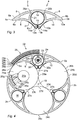
- Fig 1 shows a power cable assembly device 2 in the form of an extruded profiled body 4 with a first wall 6, a second wall 8, a third wall 10.
- the first wall 6 is convex while the second and third walls 8, 10 are concave, the reason for which will be discussed farther below.
- the cross-section of the profiled body has first and second end portions 5a, 5b, opposite to one another.
- the first wall 6 has a first end 6a and a second end 6b.
- the second wall 8 has a first end 8a and a second end 8b
- the third wall 10 has a first end 10a and a second end 10b.
- the first end 6a of the first wall 6 is connected to the first end 8a of the second wall at the first end 5a
- the second end 6b of the first wall 6 is connected to the first end 10a of the third wall 10 at the second end of the profiled body 4.
- the second end 8b of the second wall 8 continues to a first angled transition 12a and further to a first radial transition 14a.
- the second end 10b of the third wall 10 continues to a second angled transition 12b and further to a second radial transition 14b.
- the first and second angled transitions 12a, 12b are converging towards the first and second radial transitions 14a, 14b, the latter being substantially parallel to one another and thus substantially radial to the convex first wall 6.
- first and second radial transitions 14a, 14b are arranged at a distance from one another, defining an open slit 15.
- a chamber 16 defined by a substantially annular wall 18 is arranged inside the profiled body 4.
- the annular wall 18 extends from the first radial transition 14a to the second radial transition 14b.
- a pair of reinforcement members 20a, 20b are arranged between the annular wall 18 and the first wall 6.
- the number of reinforcement members could be less than two, i.e. one or zero (i.e. leaving an open space between the annular wall 18 and the first wall 6), or more than two, i.e. three, four, five or even more, depending on the space available between the circumferential walls.
- the assembly device 2 is made by extrusion of a polymer material, such as PE (e.g. MDPE or HDPE) or PVC and may have a length of several kilometres.
- PE e.g. MDPE or HDPE
- PVC polyvinyl chloride
- the annular wall 18, the first and second radial transitions 14a, 14b, the first and second angled transitions 12a, 12b and a part of the second and third walls 8, 10 are provided with a thin layer 21 of a semi conductive material.
- the thin layer 21 of semi-conductive material is produced by mixing an additive, such as carbon black, and a polymer material (such as MDPE, HDPE or PVC).
- a polymer material such as MDPE, HDPE or PVC.
- the polymer material for the profiled body as such and the semi-conductive material for the thin layer 21 are then supplied via different mouthpieces during a co-extrusion process, the supply of the semi-conductive material thus forming the thin layer 21, while the supply of the polymer material forming the rest of the profiled body 4.
- the semi-conductive layer could be in the form of a tape, applied by means of an adhesive to the surface.
- surface of the whole lateral extension of the second and third walls 8, 10 could be provided with the thin layer 21 of a semi-conductive material.
- At least the second and third walls 8, 10 have a thickness in the range 2-6 mm, more preferably 2,5 - 4 mm, most preferably 3 mm, and thin layer 21 of the semi-conductive material is in the range 0,01 - 0,5 mm, more preferably 0,05 - 0,35 mm, even more preferably 0,1 - 0,3 mm, even more preferably 0,15 - 0,25 mm, most preferably 0,2 mm.
- Fig 2 shows the interior of a power cable 22 provided with three neighbouring first, second and third power cores 24a, 24b, 24c, each provided - from the centre to the periphery - with a conductor 25a, a central semi-conductive layer 25b, insulation 25c, an intermediate semi-conductive layer 25d, a layer of swelling material 25e, a metal screen 25f made of led and a peripheral semi-conductive mantle 25g.
- the central and intermediate semi-conductive layers 25b, 25d form a smooth surface which controls the electric field strength.
- the swelling material 25e tightens against water in case the led screen 25f would start leaking.
- Each power core 24a, 24b, 24c has a peripheral point 26a, 26b, 26c in relation to the diametrical centre 19 of the power cable 22, i.e. in the central space 27d.
- the three peripheral points 26a, 26b, 26c form together in relation to the centre point 19 an imaginary circle 26d.
- the first and second power cores 24a, 24b touch one another at a contact point 23a and define a peripheral space 27a together with the imaginary circle 26d.
- the second and third power cores 24b, 24c have a contact point 23b and define a second peripheral space 27b together with the imaginary circle 26d and the third and first power cores 24c and 24a have a contact point 23c and define a third peripheral space 27c together with the imaginary circle 26d.
- the first, second and third power cores 24a, 24b, 24c define between the contact points 23a, 23b, 23c a central space 27d.
- a first assembly device 2a is provided in the peripheral space 27a.
- a second assembly device 2b is arranged in the second peripheral space 27b
- a third assembly device 2c is arranged in the third peripheral space 27c.
- the power cable is provided with a jacket 28 to keep the power cores 24a, 24b, 24c and the assembly devices 2a, 2b, 2c together as one unit and to keep the circular cylindrical shape and mechanical protection.
- the jacket 28 comprises - from the periphery towards the centre point 19 - two layers 29a of yarn made of polypropylene (PP), a first steel wire armour layer 29b, a first soft layer 29c of laying bands, a second steel wire armour layer 29d, a second soft layer 29e of laying bands.
- PP polypropylene
- the concavity of the outer surface of the second and third walls 8, 10 of each assembly device 2a, 2b, 2c depends on the diameter of the power cores 24a, 24b, 24c.
- the convexity of the outer surface of the first wall 6 of each assembly device 2a, 2b, 2c depends on the radius of curvature of the imaginary circle 26d.
- An elongated a fibre optic cable 30 comprises a fibre optic wave conductor 31, i.e. a bundle of optical fibres inside a metal tubing 32a together with a mass 32b, such as a gel.
- the metal tubing 32a is covered with a layer of semi-conductive layer 33.
- the fibre optic cable 30 is put inside the chamber 16 of assembly device 2a. In order to avoid building up of an electric potential between the fibre optic cable 30 and the power core 24a and/or 24b, it is important that a sufficient contact is established between the semi-conductive layer 33 of the metal tubing 32a of the fibre optic cable 30 and the peripheral semi-conductive mantle 25g of the core.
- Fig 3 shows a second embodiment of an assembly device 2 made by extrusion of a polymer material, such as PE (e.g. MDPE or HDPE) or PVC.
- PE e.g. MDPE or HDPE
- the first wall 6 of the profiled body 4 is convex and has first and second ends 6a, 6b; the second wall 8 is concave and has first and second ends 8a, 8b; and the third wall 10 is concave and has first and second ends 10a, 10b.
- the first, second and third walls are connected to one another as described in connection with Fig 1 above.
- the second end 8b of the second wall 8 continues to a first curved transition 13a and further to a first radial transition 14a.
- the second end 10b of the third wall 10 continues to a second curved transition 13b and further to a second radial transition 14b.
- the first and second radial transitions 14a, 14b are substantially parallel to one another and are thus substantially radial to the convex first wall 6.
- the first and second radial transitions 14a, 14b are arranged without distance from one another, i.e. the slit 15 is closed at least when mounted, even though the slit for clarity reasons have been shown to be somewhat open.
- the annular wall 18 defining the chamber 16 extends from the first radial transition 14a to the second radial transition 14b. However, no further reinforcement members are needed. Instead, the annual wall 18 is partly constituted by the first wall 6.
- the annular wall 18, the first and second radial transitions 14a, 14b, the first and second curved transitions 13a, 13b and a part of the second and third walls 8, 10 are provided with a thin layer of a semi-conductive layer 21, such as carbon black mixed into a polymer material (e.g. PE or PVC) before the co-extrusion process.
- a semi-conductive layer 21 such as carbon black mixed into a polymer material (e.g. PE or PVC) before the co-extrusion process.
- the whole lateral extension of the second and third walls 8, 10 could be provided with the thin layer 21 of a semi-conductive material.
- Fig 4 shows the interior of a power cable 22 provided with three neighbouring first, second and third power cores 24a, 24b, 24c provided are built up in a manner corresponding to that of the embodiment of Figure 2 , and are thus each provided with a peripheral semi-conductive mantle 25g touching one another.
- first, second and third assembly devices 2a, 2b, 2c are arranged in the peripheral spaces between the first, second and third power cores 24a, 24b, 24c, respectively.
- a fibre optic cable 30 is put inside the chamber 16 of assembly device 2a.
- the thin layer 21 of semi-conductive layer of the thickness range presented above extends from the second wall 8, to the first curved transition 13a, continuing via the first radial transition 14a to and around the annular wall 18 and further to the second radial transition 14b and continuing via the second radial transition 13b to the third wall 10.
- a contact to the thin layer 21 of semi-conductive material will be established disregarding which part of the annular wall 18 is contacted by the fibre optic cable 30.
- Contact is also established between the power cores 24a, 24b via the peripheral semi-conductive mantle 25g of each power core and the thin layer 21 of semi-conductive layer of the second and third walls 8, 10, and furthermore via the contact point 23a.
- the power cable assembly device of Fig 1 could be provided with a slit 15 of the kind shown and described in connection with Fig 3 .
- the power cable assembly device of Fig 3 could be provided with a slit 15 of the kind shown and described in connection with Fig 1 .
- Figure 5a shows a further variant of the tool 39 provided with support means 46 comprising four support members 48 in the form of double encapsulated ball-bearings 54.
- Each ball-bearing 54 is rotatably connected via an axle 72 to a U-shaped bearing support 73 across an axis through the aligned ball-bearings 54.
- the tool 39 is furthermore provided with guide means in the form of four pairs of guide wheels 41a, 41b of encapsulated needle bearings 55a, 55b, each rotatable about an axle 76, said axle 76 being parallel to the axles 72 of the ball-bearings 54.
- the tool 39 comprises a grid of parallel plates 75 of a first frame part. 74a of an interconnection means 44 in the form of a frame 74, together forming a grid.
- the grid of parallel plates 75 could instead be constituted by a single plate.
- the frame further comprises a pair of side walls 74b, 74c, connected perpendicularly to the first frame part 74a by screws 90.
- the side walls 74b, 74c are furthermore adjustably connected to a frame support 74f by screws 94 in a row of holes 96.
- the first frame part 74a can be moved in a direction across the row of holes 96.
- the position of a plane through the axles 72 of the ball-bearings 54 can be adjusted in relation to the guide wheels 41a, 41 b, depending on the thickness of the profiled body 4.
- the frame support 74f is provided with an entrance opening 92 for introduction of the profiled body 4 into the tool 39.
- An access slot 93 in the frame support 74e allows for taking the tool 39 apart even if the profiled body 4 is still inside the tool 39.
- the frame 74 further comprises a pair of plates 74d, 74e each connected to extension plates 74g, 74h.
- the plates 74d, 74e are each provided with a slot 97a, 97b in their opposing ends (the rear ends being hidden) for adjustable connection with screws 98a, 98b to a pair of rows of holes 99 in the frame support 74f.
- the frame 74 is adjusted for the lateral dimension of the profiled body 4.
- a pair of reinforcement members 74i, 74k are each provided with four sets of screws 80a.
- Each guide wheel 41a, 41b is independently movable in a slot 78 in the plates 74d, 74e towards a plane through the axles 72 of the ball-bearings 54, and is adjustable in the slot 78 by means of a corresponding set screw 80a. After performed adjustment, the position of the guide wheel 41a or 41b is fixed by means of a lock nut 80b.
- the set of screws 80a and lock nuts 80b are adjusted in such a way that each guide wheel 41a, 41b is positioned at a predetermined distance relative to the support member 48. In this way, it is possible to adjust each pairs of guide wheels 41a, 41b relative to the other pairs of guide wheels 41a, 41b to bear against the edges of 5a, 5b of the profiled body 4. By said adjustment, the slit 15 will be widened and thus opened at a predetermined position between the first pair of wheels and the fourth pair of wheels.
- Fig 5b is shown an elongated guide beam 82 having lateral sides 82a, 82b, a guide side 82c and a connection side 82d (hidden).
- the guide beam 82 is to be arranged opposite to and facing the support members 48.
- the guide beam 82 is provided with an elongated guide member 84 to be positioned parallel to a plane through the axles 72 of the ball-bearings 54, by screws 83a in elongated slits 83b, 83c in two pairs of arms 83d, 83e connected to the side walls 74b, 74c of the frame 74.
- Fig 5c is shown the guide beam 82 from the opposite direction.
- an elongated U-shaped guide member 85 is provided, while at a second end 82f, and on the same longitudinal side 82c, an elongated guide member 84 is provided.
- a transition section 86a is provided between first and second sections 86b, 86c.
- the lateral extension of the elongated U-shaped member 85 measured from the connection side 82d is reduced in a longitudinal direction from the first section 86b towards the elongated guide member 84.
- the lateral extension of the elongated member 84 measured from the connection side 82d is reduced in a longitudinal direction from the second section 86c towards the U-shaped member 85.
- Fig 5d is shown that the fibre optic cable 30 is controlled to keep a longitudinal orientation relative to the slit 15 of the profiled body by the U-shaped guide member 85 at the first section 86b extending from the first end 82e to the transition section 86a. It also shows that the fibre optic cable is introduced into the profiled body 4 via slit 15 by the transition section 86a of the diminishing elongated U-shaped guide member 85 and the raising elongated guide member 84, and that the fibre optic cable 30 is guided to stay inside the chamber by the elongated guide member 84 in the section 86c extending from the transition section 86a towards the second end 82f.
- Fig 6 shows the first step of assembly of the power cable.
- the power cores 24a, 24b, 24c are held 120° in relation to one another by means of not shown equipment in the periphery of an imaginary circle 100.
- the frame 74 is adjusted for the power cable assembly device 2 to be used, i.e. first frame part 74a is mounted in predetermined holes of the frame support 74f, and the pair of plates 74d, 74e are mounted in predetermined holes 99.
- a profiled body 4 is positioned between the four pairs of guide wheels 41a, 41b, starting from the level of frame support 74f (i.e. seen from the lower part in fig 5a ) and the four support members 48.
- the screws 80a of the first, second and third pairs of wheels 41 a, 41b, counted from the frame support 74f, are adjusted such that the slit 15 of the profiled body 4 of Fig 1 or Fig 3 is opened somewhat more than the diameter of the fibre optic cable 30, while the fourth pair of wheels 41a, 41b are adjusted to allow the slit 15 to be smaller, such that the width of the slit is less than the diameter of the fibre optic cable 30, but wider than the transversal dimension of the guide member 84.
- a fibre optic cable 30 is now introduced via the entrance opening 92 of the frame 74 (cf. Fig 5 ) in each profiled body 30 mounted in the tools 39a, 39b, 39c, and is introduced into the chamber 16 and through the end of the profiled body 4 and temporarily fixed inside the profiled body upon start.
- a guide beam 82 of the kind described above is then mounted.
- Each profiled body 4 is collected together with the power cores 24a, 24b, 24c at a distance from the tools 39a, 39b, 39c (above the tools as seen in Fig 5a and Fig 6 ) and are assembled while pulling the profiled bodies 4 and power cores 24a, 24b, 24c away from the tools 39a, 39b, 39c.
- the slit 15 is opened by the support members 48 and the guide members 41, while fibre optic cables 30 are guided into the chamber by the guide beam 82.
- the tools 39a, 39b, 39c may be mounted for introduction of the fibre optic cable 30 through the entrance opening 92 of the frame 74 horizontally or vertically.
- a higher pressure may have to be applied on one side 8 than the other 10 by the guide wheels 41a, 41b, or a pressure may even only be applied on one side 8 by one or more guide wheels 41a, while a lower or even no pressure may be applied on the other side 10 by one or more guide wheels 41b.
- the guide beam 82 could instead be divided into three different items, corresponding to the sections 86a, 86b and 86c.
- the first and second sections 86b, 86c could instead be a pair of wheels with a peripheral shape corresponding to the cross-section of the first and second sections 86b, 86c, respectively.
- the encapsulated ball-bearing 54 could be exchanged to an encapsulated roller bearing, having circular cylindrical rollers, or to plain bearings.
- the encapsulated needle-bearings could be exchanged to small ball-bearings or plain bearings.
- the bearings could also be non-encapsulated.
Landscapes
- Physics & Mathematics (AREA)
- General Physics & Mathematics (AREA)
- Optics & Photonics (AREA)
- Spectroscopy & Molecular Physics (AREA)
- Cable Accessories (AREA)
- Communication Cables (AREA)
- Installation Of Indoor Wiring (AREA)
Description
- The present invention relates to a power cable assembly device adapted to be arranged in the spaces between neighbouring power cores of a power cable, comprising an extruded profiled body made of a polymer material and adapted to the cross-sectional shape and elongation of the power cable, said profiled body comprising a chamber and defining a slit to said chamber, said chamber being adapted to receive a fibre optic cable via said slit.
- It also relates to a power cable comprising such a power cable assembly device.
- When putting a power cable in the ground, or on the sea floor, it is often practical to add a fibre optic cable in a space between the power cores.
- A power cable assembly device, a power cable and a tool is known from SE-C2-530 277, respectively. The known assembly device however suffers from inefficient equalisation of electric potential.
- According to
DE-A1-195 08 888 A1, the fibre optic cable is put inside a metal tubing placed at two of the power cores with the intention to provide contact between the metal tubing and the outer conductive plastic material of the power core, in order to equalize the electric potential between the power core and the metal tubing. - The object is to provide a power cable assembly device and a power cable, which is possible to test on land or with insufficient contact with sea-water, even if not correctly earthed, without risking that the fibre optic cable is damaged when testing or operating the power cable.
- This object has been achieved by the assembly device and the power cable, further comprising the features that, substantially the whole surface of the profiled body inside the chamber and the surface of the profiled body defining the slit, and at least a region outside the profiled body extending from the slit and away from the slit is provided with a layer of semi-conductive material.
- Hereby is achieved an improved equalisation of the electric potential between the power cores and the semi-conductive outer layer of the power core and the semi-conductive outer layer of the fibre optic cable.
- Furthermore is achieved a less expensive production method of the assembly device, since less semi-conductive material needs to be used.
- In particular, the cross-section of the profiled body includes a first wall, a second wall and a third wall,
said first wall being convex and having first and second opposite end portions,
said second wall being concave and having third and fourth opposite end portions, said third wall being concave and having fifth and sixth end portions,
the third end portion of said second wall being connected to said first end portion of said first wall,
the fifth end portion of said third wall being connected to said second end portion of
the first wall,
the first wall being adapted to face a jacket of the power cable,
said a second and a third walls being adapted to face a pair of neighbouring power cores,
wherein the fourth end portion of the second wall and the sixth end portion of the third wall define together a slit to a chamber between said first, second and third walls, said slit extending in the elongation of the profile for allowing introduction of a fibre optic cable into said chamber. Hereby, the profiled body is further defined. - Suitably, the cross-section of the chamber is substantially annular. Hereby, an optimal shape of the chamber is achieved. Of course, the annular chamber could be polygonal rather than circular.
- Suitably, also the semi-conductive material of the layer comprises a polymer material. A mixture of PE and an additive would be preferable, even though a mixture of PVC and an additive would be possible. In particular, said additive could be carbon black.
- Hereby is achieved a cost-efficient semi-conductive material with good mechanical and blending properties to the non-conductive material.
- Preferably, the thickness of said layer is in the
range 0,01 - 0,5 mm, more preferably 0,05 - 0,35 mm, even more preferably 0,1 - 0,3 mm, even more preferably 0,15 - 0,25 mm, most preferably 0,2 mm. Hereby, a low consumption of the additive is achieved during manufacture of the assembly device. Furthermore, a layer adapted for the voltage of the power cable is achieved. - Suitably, said elongated slit is closed in an assembled state. Hereby is achieved a power cable assembly device with high mechanical stability. In such a case, the diameter of the chamber is in the range 11 - 25 mm, more preferably 13 - 23 mm. In this case, the diameter of the chamber can be chosen without dependency of the slit width.
- Alternatively, the slit is open in an assembled state, and the slit width, i.e. the distance between the fourth end portion of the second wall and the sixth end portion of the third wall defining the slit is in the range 1 mm - 13 mm, more preferably 3 - 11 mm, even more preferably 4 - 6 mm, most preferably 5 mm. Hereby the insertion of a fibre optic cable is made allowed to be performed readily and easily. The slit width should be chosen such that the diameter of the fibre optic cable including cover is 1 - 5 mm larger than the slit width.
- Alternatively, the diameter of the chamber is in the range 11 - 25 mm, more preferably 12 - 23 mm.
- The combination of the fact that the material used is watertight and that the slit is closed, no or only small amounts of water will circulate in the chamber, which makes the need for an efficient equalisation of the electric potential even more important, since no contribution for this purpose by water is achieved.
- Preferably, the wall thickness of either or all of the second wall, the third wall and a wall defining the chamber has a thickness in the range of 2 - 6 mm, more preferably 2,5 - 4 mm, most preferably 3 mm.
- Suitably, the concavity of the outer surface of the second and the third walls, respectively, is adapted to the number of power cores and the diameter of the power cores including insulation. Hereby, a tight fit will be achieved between the assembly profile and neighbouring power cores, and the power cores and the profiles will form a power cable with a substantially circular cross-section with high mechanical stability.
- The convexity of the outer surface of the first wall is suitably adapted to an imaginary circle between a peripheral point of each power core in relation to the diametrical centre point of the power cable. Hereby is achieved a power cable with large form stability when assembled, i.e. the cross-section of the assembled power cable with be substantially circular also at the high pressures on the bottom of sea bottom at large depths.
- Suitably, the number of power cores is three and the number of power cable assembly devices is three. The diameter of each power core is in the range of 30 - 140 mm, more preferably 40 - 130 mm.
- Further, the invention relates to a power cable comprising a plurality of power cable assembly devices according to the invention as defined herein, said power cable assembly devices arranged in the spaces between neighbouring power cores, at least one of said power cord assembly devices containing a fibre optic cable introduced via said slit.
- Further, the first wall faces a jacket of the power cable, said second and third walls face a pair of neighbouring power cores, and at least one of said assembly devices containing said fibre optic cable.
- Suitably, the concavity of the second and the third walls, respectively, is adapted to the number of power cores and the diameter of the power cores in the power cable.
- In addition it is also referred to a power cable, wherein the convexity of the first wall is adapted to an imaginary circle between a peripheral point of each power core in relation to the diametrical centre point of the power cable.
- Suitably, the number of power cores is three and the number of power cable assembly devices is three, and the diameter of each power core is in the range 40 - 140 mm, more preferably 50 - 130 mm.
- In the following, the invention will be described in more detail by reference to the enclosed drawings, in which
-
Fig 1 is a cross-section of a power cable assembly device according to a first embodiment of the invention; -
Fig 2 is a cross-section of the interior of a power cable provided with the power cable assembly body shown inFig 1 ; -
Fig 3 is a cross-section of a power cable assembly body according to a second embodiment of the invention; -
Fig 4 is a cross-section of the interior of a power cable provided with the power cable assembly body shown inFig 3 ; -
Figs 5a - 5d illustrate a tool for introduction of a fibre optic cable in a power cable assembly device shown infigures 1 and3 ; and -
Fig 6 illustrates a set up of tools in the assembly of a power cable. -
Fig 1 shows a powercable assembly device 2 in the form of an extruded profiledbody 4 with afirst wall 6, asecond wall 8, athird wall 10. Thefirst wall 6 is convex while the second andthird walls second end portions - The
first wall 6 has afirst end 6a and asecond end 6b. Likewise, thesecond wall 8 has afirst end 8a and asecond end 8b, and thethird wall 10 has afirst end 10a and asecond end 10b. Thefirst end 6a of thefirst wall 6 is connected to thefirst end 8a of the second wall at thefirst end 5a, while thesecond end 6b of thefirst wall 6 is connected to thefirst end 10a of thethird wall 10 at the second end of the profiledbody 4.
Thesecond end 8b of thesecond wall 8 continues to a firstangled transition 12a and further to a firstradial transition 14a. Likewise, thesecond end 10b of thethird wall 10 continues to a secondangled transition 12b and further to a secondradial transition 14b. - The first and second
angled transitions radial transitions first wall 6. - According to this embodiment, the first and second
radial transitions open slit 15. - Inside the profiled
body 4, achamber 16 defined by a substantiallyannular wall 18 is arranged. Theannular wall 18 extends from the firstradial transition 14a to the secondradial transition 14b. A pair ofreinforcement members annular wall 18 and thefirst wall 6. Of course, the number of reinforcement members could be less than two, i.e. one or zero (i.e. leaving an open space between theannular wall 18 and the first wall 6), or more than two, i.e. three, four, five or even more, depending on the space available between the circumferential walls. - The
assembly device 2 is made by extrusion of a polymer material, such as PE (e.g. MDPE or HDPE) or PVC and may have a length of several kilometres. - The
annular wall 18, the first and secondradial transitions angled transitions third walls thin layer 21 of a semi conductive material. - The
thin layer 21 of semi-conductive material is produced by mixing an additive, such as carbon black, and a polymer material (such as MDPE, HDPE or PVC). The polymer material for the profiled body as such and the semi-conductive material for thethin layer 21 are then supplied via different mouthpieces during a co-extrusion process, the supply of the semi-conductive material thus forming thethin layer 21, while the supply of the polymer material forming the rest of the profiledbody 4. - Alternatively, the semi-conductive layer could be in the form of a tape, applied by means of an adhesive to the surface.
- Of course, surface of the whole lateral extension of the second and
third walls thin layer 21 of a semi-conductive material. - At least the second and
third walls thin layer 21 of the semi-conductive material is in therange 0,01 - 0,5 mm, more preferably 0,05 - 0,35 mm, even more preferably 0,1 - 0,3 mm, even more preferably 0,15 - 0,25 mm, most preferably 0,2 mm. - The function of the
layer 21 of semi-conductive material will be explained farther below. -
Fig 2 shows the interior of apower cable 22 provided with three neighbouring first, second andthird power cores conductor 25a, acentral semi-conductive layer 25b,insulation 25c, anintermediate semi-conductive layer 25d, a layer of swellingmaterial 25e, ametal screen 25f made of led and a peripheralsemi-conductive mantle 25g. - The central and intermediate
semi-conductive layers material 25e tightens against water in case the ledscreen 25f would start leaking. - Each
power core peripheral point diametrical centre 19 of thepower cable 22, i.e. in thecentral space 27d. The threeperipheral points centre point 19 animaginary circle 26d. - The first and
second power cores contact point 23a and define aperipheral space 27a together with theimaginary circle 26d. Likewise, the second andthird power cores contact point 23b and define a secondperipheral space 27b together with theimaginary circle 26d and the third andfirst power cores contact point 23c and define a thirdperipheral space 27c together with theimaginary circle 26d. The first, second andthird power cores contact points central space 27d. - In the
peripheral space 27a, afirst assembly device 2a is provided. Likewise, asecond assembly device 2b is arranged in the secondperipheral space 27b, and athird assembly device 2c is arranged in the thirdperipheral space 27c. - The power cable is provided with a
jacket 28 to keep thepower cores assembly devices jacket 28 comprises - from the periphery towards the centre point 19 - twolayers 29a of yarn made of polypropylene (PP), a first steelwire armour layer 29b, a firstsoft layer 29c of laying bands, a second steelwire armour layer 29d, a secondsoft layer 29e of laying bands. - As can be understood from
Fig 2 , the concavity of the outer surface of the second andthird walls assembly device power cores first wall 6 of eachassembly device imaginary circle 26d. - An elongated a
fibre optic cable 30 comprises a fibreoptic wave conductor 31, i.e. a bundle of optical fibres inside ametal tubing 32a together with a mass 32b, such as a gel. Themetal tubing 32a is covered with a layer ofsemi-conductive layer 33. Thefibre optic cable 30 is put inside thechamber 16 ofassembly device 2a. In order to avoid building up of an electric potential between thefibre optic cable 30 and thepower core 24a and/or 24b, it is important that a sufficient contact is established between thesemi-conductive layer 33 of themetal tubing 32a of thefibre optic cable 30 and the peripheralsemi-conductive mantle 25g of the core. This is performed during assembly first by introducing thefibre optic cable 30 into thechamber 16, and then by putting the concave second andthird walls assembly device 2a against thepower cores thin layer 21 of semi-conductive material of the second andthird walls semi-conductive mantle 25g. Owing to the fact that thethin layer 21 of semi-conductive layer extends from thesecond wall 8, to the firstangled transition 12a, continuing via the firstradial transition 14a to and about theannular wall 18 and further to the secondradial transition 14b and continuing via the secondangular transition 12b to thethird wall 10, a contact to thethin layer 21 semi-conductive will be established disregarding which part of theannular wall 18 is contacted by thesemi-conductive layer 33 of themetal tubing 32a of thefibre optic cable 30. Electric contact is also established between the peripheralsemi-conductive mantle 25g of each of thepower cores contact point 23a. - Consequently, the risk for a building up of an electric potential between the
fibre optic cable 30 and thepower cores 24a and/or 24b or any other surrounding metallic parts, such as the armour layers is avoided. - Of course, this relates correspondingly to the case when a fibre optic cable is put inside the chamber of the
assembly devices 2b and/or 2c. -
Fig 3 shows a second embodiment of anassembly device 2 made by extrusion of a polymer material, such as PE (e.g. MDPE or HDPE) or PVC. - Also in this embodiment, the
first wall 6 of the profiledbody 4 is convex and has first andsecond ends second wall 8 is concave and has first andsecond ends third wall 10 is concave and has first andsecond ends Fig 1 above. - However according to this embodiment, the
second end 8b of thesecond wall 8 continues to a firstcurved transition 13a and further to a firstradial transition 14a. Likewise, thesecond end 10b of thethird wall 10 continues to a secondcurved transition 13b and further to a secondradial transition 14b. Also in this embodiment the first and secondradial transitions first wall 6. - However, according to this embodiment, the first and second
radial transitions slit 15 is closed at least when mounted, even though the slit for clarity reasons have been shown to be somewhat open. - Also in this embodiment, the
annular wall 18 defining thechamber 16 extends from the firstradial transition 14a to the secondradial transition 14b. However, no further reinforcement members are needed. Instead, theannual wall 18 is partly constituted by thefirst wall 6. - According to this embodiment, the
annular wall 18, the first and secondradial transitions curved transitions third walls semi-conductive layer 21, such as carbon black mixed into a polymer material (e.g. PE or PVC) before the co-extrusion process. - Also in this embodiment, the whole lateral extension of the second and
third walls thin layer 21 of a semi-conductive material. -
Fig 4 shows the interior of apower cable 22 provided with three neighbouring first, second andthird power cores Figure 2 , and are thus each provided with a peripheralsemi-conductive mantle 25g touching one another. - Also in this case, first, second and
third assembly devices third power cores - A
fibre optic cable 30 is put inside thechamber 16 ofassembly device 2a. - According to this embodiment, the
thin layer 21 of semi-conductive layer of the thickness range presented above extends from thesecond wall 8, to the firstcurved transition 13a, continuing via the firstradial transition 14a to and around theannular wall 18 and further to the secondradial transition 14b and continuing via the secondradial transition 13b to thethird wall 10. Thus, a contact to thethin layer 21 of semi-conductive material will be established disregarding which part of theannular wall 18 is contacted by thefibre optic cable 30. Contact is also established between thepower cores semi-conductive mantle 25g of each power core and thethin layer 21 of semi-conductive layer of the second andthird walls contact point 23a. - In this manner, and as already explained above in connection with
figures 1 and 2 , the risk for a building up of an electric potential between thefibre optic cable 30 and thepower cores 24a and/or 24b is avoided. - Again, this relates correspondingly to the case when a fibre optic cable is put inside the chamber of the
assembly bodies 2b and/or 2c. - It is to be understood that the power cable assembly device of
Fig 1 could be provided with aslit 15 of the kind shown and described in connection withFig 3 . - Furthermore, it is to be understood that the power cable assembly device of
Fig 3 could be provided with aslit 15 of the kind shown and described in connection withFig 1 . -
Figure 5a shows a further variant of thetool 39 provided with support means 46 comprising foursupport members 48 in the form of double encapsulated ball-bearings 54. Each ball-bearing 54 is rotatably connected via anaxle 72 to aU-shaped bearing support 73 across an axis through the aligned ball-bearings 54. Thetool 39 is furthermore provided with guide means in the form of four pairs ofguide wheels needle bearings axle 76, saidaxle 76 being parallel to theaxles 72 of the ball-bearings 54. - In order to position the four ball-
bearings 54 in relation to one another and in relation to the guide wheels, thetool 39 comprises a grid ofparallel plates 75 of a first frame part. 74a of an interconnection means 44 in the form of aframe 74, together forming a grid. Of course, the grid ofparallel plates 75 could instead be constituted by a single plate. - The frame further comprises a pair of
side walls first frame part 74a by screws 90. Theside walls frame support 74f byscrews 94 in a row ofholes 96. In this manner, thefirst frame part 74a can be moved in a direction across the row ofholes 96. Thus, the position of a plane through theaxles 72 of the ball-bearings 54 can be adjusted in relation to theguide wheels body 4. - The
frame support 74f is provided with anentrance opening 92 for introduction of the profiledbody 4 into thetool 39. Anaccess slot 93 in the frame support 74e allows for taking thetool 39 apart even if the profiledbody 4 is still inside thetool 39. - The
frame 74 further comprises a pair of plates 74d, 74e each connected toextension plates slot screws holes 99 in theframe support 74f. Hereby, theframe 74 is adjusted for the lateral dimension of the profiledbody 4. - A pair of
reinforcement members screws 80a. Eachguide wheel slot 78 in the plates 74d, 74e towards a plane through theaxles 72 of the ball-bearings 54, and is adjustable in theslot 78 by means of acorresponding set screw 80a. After performed adjustment, the position of theguide wheel lock nut 80b. - The set of
screws 80a and lock nuts 80b are adjusted in such a way that eachguide wheel support member 48. In this way, it is possible to adjust each pairs ofguide wheels guide wheels body 4. By said adjustment, theslit 15 will be widened and thus opened at a predetermined position between the first pair of wheels and the fourth pair of wheels. - In
Fig 5b is shown anelongated guide beam 82 havinglateral sides guide side 82c and aconnection side 82d (hidden). Theguide beam 82 is to be arranged opposite to and facing thesupport members 48. Theguide beam 82 is provided with anelongated guide member 84 to be positioned parallel to a plane through theaxles 72 of the ball-bearings 54, byscrews 83a inelongated slits arms side walls frame 74. - In
Fig 5c is shown theguide beam 82 from the opposite direction. At afirst end 82e of the guide beam, an elongatedU-shaped guide member 85 is provided, while at asecond end 82f, and on the samelongitudinal side 82c, anelongated guide member 84 is provided. Between the elongated guide, theU-shaped member 85 and theelongated guide member 84, atransition section 86a is provided between first andsecond sections transition section 86a, the lateral extension of the elongatedU-shaped member 85, measured from theconnection side 82d is reduced in a longitudinal direction from thefirst section 86b towards theelongated guide member 84. Furthermore, in thetransition section 86a the lateral extension of theelongated member 84, measured from theconnection side 82d is reduced in a longitudinal direction from thesecond section 86c towards theU-shaped member 85. - In
Fig 5d is shown that thefibre optic cable 30 is controlled to keep a longitudinal orientation relative to theslit 15 of the profiled body by theU-shaped guide member 85 at thefirst section 86b extending from thefirst end 82e to thetransition section 86a. It also shows that the fibre optic cable is introduced into the profiledbody 4 viaslit 15 by thetransition section 86a of the diminishing elongatedU-shaped guide member 85 and the raisingelongated guide member 84, and that thefibre optic cable 30 is guided to stay inside the chamber by theelongated guide member 84 in thesection 86c extending from thetransition section 86a towards thesecond end 82f. -
Fig 6 shows the first step of assembly of the power cable. - First, the
power cores - Then, between the
power cores tools Figs 5a-d , are arranged 120° in relation to one another in the periphery of the imaginary circle 100 in relation to and between thepower cores - As explained above in connection with
Fig 5a , theframe 74 is adjusted for the powercable assembly device 2 to be used, i.e.first frame part 74a is mounted in predetermined holes of theframe support 74f, and the pair of plates 74d, 74e are mounted inpredetermined holes 99. - In each
tool body 4 is positioned between the four pairs ofguide wheels frame support 74f (i.e. seen from the lower part infig 5a ) and the foursupport members 48. - The
screws 80a of the first, second and third pairs ofwheels frame support 74f, are adjusted such that theslit 15 of the profiledbody 4 ofFig 1 orFig 3 is opened somewhat more than the diameter of thefibre optic cable 30, while the fourth pair ofwheels slit 15 to be smaller, such that the width of the slit is less than the diameter of thefibre optic cable 30, but wider than the transversal dimension of theguide member 84. - A
fibre optic cable 30 is now introduced via the entrance opening 92 of the frame 74 (cf.Fig 5 ) in each profiledbody 30 mounted in thetools chamber 16 and through the end of the profiledbody 4 and temporarily fixed inside the profiled body upon start. - A
guide beam 82 of the kind described above is then mounted. - Each profiled
body 4 is collected together with thepower cores tools Fig 5a andFig 6 ) and are assembled while pulling the profiledbodies 4 andpower cores tools - During this movement, the
slit 15 is opened by thesupport members 48 and the guide members 41, whilefibre optic cables 30 are guided into the chamber by theguide beam 82. - It should also be noted that the
tools fibre optic cable 30 through the entrance opening 92 of theframe 74 horizontally or vertically. - In case of high torsional stiffness of the profiled
body 4, a higher pressure may have to be applied on oneside 8 than the other 10 by theguide wheels side 8 by one ormore guide wheels 41a, while a lower or even no pressure may be applied on theother side 10 by one ormore guide wheels 41b. - In Figure 11, the simultaneous introduction of a
fibre optic cable 30 into three powercable assembly devices 2 of apower cable 22. However, in case only one or twofibre optic cables 30 are to be introduced into the power cable, thetools cores support members 48 andguide wheels bodies 4 will not be opened. - It should be noted that the
guide beam 82 could instead be divided into three different items, corresponding to thesections second sections second sections - It should be noted that the encapsulated ball-bearing 54 could be exchanged to an encapsulated roller bearing, having circular cylindrical rollers, or to plain bearings. Likewise, the encapsulated needle-bearings could be exchanged to small ball-bearings or plain bearings. Of course the bearings could also be non-encapsulated.
Claims (18)
- A power cable assembly device adapted to be arranged in the spaces between neighbouring power cores (24a, 24b, 24c) of a power cable (22), comprising an extruded profiled body (4) made of a polymer material and adapted to the cross-sectional shape and elongation of the power cable, said profiled body (4) comprising a chamber (16) and defining a slit (15) to said chamber, said chamber being adapted to receive a fibre optic cable (30) via said slit, characterised in that substantially the whole surface of the profiled body (4) inside the chamber (16), the surface of the profiled body defining the slit (15), and the surface of at least a region outside the profiled body (4) extending from the slit and away from the slit (15) is provided with a layer (21) of semi-conductive material.
- A power cable assembly device according to claim 1, wherein
the cross-section of the profiled body (4) includes a first wall (6), a second wall (8) and a third wall (10),
said first wall (6) being convex and having first and second opposite end portions (6a, 6b),
said second wall (8) being concave and having third and fourth opposite end portions (8a, 8b),
said third wall (10) being concave and having fifth and sixth end portions (10a, 10b), the third end portion (8a) of said second wall (8) being connected to said first end portion (6a) of said first wall (6),
the fifth end portion (10a) of said third wall (10) being connected to said second end portion (6b) of the first wall (6),
the first wall (6) being adapted to face a jacket of the power cable (22),
said second and third walls (8, 10) being adapted to face a pair of neighbouring power cores (24a, 24b, 24c),
wherein the fourth end portion (8b) of the second wall (8) and the sixth end portion (10b) of the third wall (10) define together a slit (15) to a chamber (16) inside said profiled body (4), said slit extending in the elongation of the profile for allowing introduction of a fibre optic cable (30) into said chamber. - A power cable assembly device according to claim 1 or 2, wherein the cross-section of the chamber (16) is substantially annular.
- A power cable assembly device according to any one of claims 1 - 3, wherein the semi-conductive material of the layer (21) comprises a mixture of a polymer material and an additive.
- A power cable assembly device according to claim 4, wherein the polymer material of the profiled body (4) and the polymer material of the semi-conductive layer is chosen from PVC and PE.
- A power cable assembly device according to any one of the preceding claims, wherein the thickness of said layer (21) is in the range 0,01 - 0,5 mm, more preferably 0,05 - 0,35 mm, even more preferably 0,1 - 0,3 mm, even more preferably 0,15 - 0,25 mm, most preferably 0,2 mm.
- A power cable assembly device according to any one of claims 1 to 3, wherein said elongated slit (15) is closed in an assembled state.
- A power cable assembly device according to claim 6, wherein the diameter of the chamber (16) is in the range 11 - 25 mm, more preferably 13 - 23 mm.
- A power cable assembly device according to any one of claims 2 - 7, wherein the slit is open in a mounted state, and the distance between the fourth end portion (8b) of the second wall (8) and the sixth end portion (10b) of the third wall (10) defining the slit (15) is in the range 1 mm - 13 mm, more preferably 3 - 11 mm, even more preferably 4 - 6 mm, most preferably 5 mm.
- A power cable assembly device according to claim 11, wherein the diameter of the chamber (16) is in the range 11 - 25 mm, more preferably 12-23 mm.
- A power cable assembly device according to any one of claims 2 - 10, wherein the wall thickness of either or all of the second wall (8), the third wall (10) and a wall (18) defining the chamber (16) has a thickness in the range of 2-6 mm, more preferably 2,5 - 4 mm, most preferably 3 mm.
- A power cable assembly device according to any claims 2 - 11, wherein the concavity of the outer surface of the second and third walls (8, 10), respectively, is adapted to the number of power cores (24a, 24b, 24c) and the diameter of the power cores.
- A power cable assembly device according to any one of claims 2-12, wherein the convexity of the outer surface of the first wall (6) is adapted to an imaginary circle between a peripheral point (26a, 26b, 26c) of each power core (24a, 24b, 24c) in relation to the diametrical centre point (19) of the power cable.
- A power cable comprising a plurality of power cable assembly devices according to any one of the preceding claims, said power cable assembly devices (2a, 2b, 2c) arranged in the spaces between neighbouring power cores (24a, 24b, 24c), at least one of said power cord assembly devices (2a, 2b, 2c) containing a fibre optic cable (30) introduced via said slit (15).
- A power cable according to claim 14, wherein
the first wall (6) faces a jacket (28) of the power cable (22),
said second and third walls (8, 10) face a pair of neighbouring power cores (24a, 24b, 24c),
at least one of said assembly devices (2a, 2b, 2c) containing said fibre optic cable (30). - A power cable according to claim 14 or 15, wherein the concavity of the second and the third walls (8, 10), respectively, is adapted to the number of power cores (24a, 24b, 24c) and the diameter of the power cores.
- A power cable according to any one of claims 14 - 16, wherein the convexity of the first wall (6) is adapted to an imaginary circle between a peripheral point (26) of each power core (24a, 24b, 24c) in relation to the diametrical centre point (19) of the power cable.
- A power cable according to any one of claims 14 - 17, wherein the number of power cores (24a, 24b, 24c) is three and the number of power cable assembly devices (4, 4a, 4b, 4c) is three, and wherein the diameter of each power core (24a, 24b, 24c) is in the range 40-140 mm, more preferably 50 - 130 mm.
Applications Claiming Priority (1)
| Application Number | Priority Date | Filing Date | Title |
|---|---|---|---|
| PCT/EP2013/062818 WO2014202140A1 (en) | 2013-06-19 | 2013-06-19 | A power cable assembly device and a power cable provided with such a device |
Publications (2)
| Publication Number | Publication Date |
|---|---|
| EP3011374A1 EP3011374A1 (en) | 2016-04-27 |
| EP3011374B1 true EP3011374B1 (en) | 2017-04-12 |
Family
ID=48652102
Family Applications (1)
| Application Number | Title | Priority Date | Filing Date |
|---|---|---|---|
| EP13729756.0A Active EP3011374B1 (en) | 2013-06-19 | 2013-06-19 | A power cable assembly device and a power cable provided with such a device |
Country Status (4)
| Country | Link |
|---|---|
| US (1) | US9502157B2 (en) |
| EP (1) | EP3011374B1 (en) |
| CN (1) | CN105474063B (en) |
| WO (1) | WO2014202140A1 (en) |
Families Citing this family (5)
| Publication number | Priority date | Publication date | Assignee | Title |
|---|---|---|---|---|
| DE102016224415A1 (en) * | 2016-12-08 | 2018-06-14 | Leoni Kabel Gmbh | Line and method for producing such |
| CN109799579A (en) * | 2019-02-19 | 2019-05-24 | 富晋精密工业(晋城)有限公司 | Optical fiber intersects optical cable |
| EP4199008A1 (en) * | 2021-12-17 | 2023-06-21 | Nexans | Power cable |
| CN114496411A (en) * | 2021-12-20 | 2022-05-13 | 中天科技海缆股份有限公司 | Submarine cable, submarine cable assembly, submarine cable cabling device and molding method |
| EP4418283A1 (en) * | 2023-02-20 | 2024-08-21 | NKT HV Cables AB | Submarine power cable with fluid transport capability |
Family Cites Families (10)
| Publication number | Priority date | Publication date | Assignee | Title |
|---|---|---|---|---|
| US4705353A (en) * | 1983-03-28 | 1987-11-10 | Schlumberger Technology Corporation | Optical fiber cable construction |
| DE19508888C2 (en) | 1995-03-11 | 1998-04-09 | Alcatel Kabel Ag | Flexible electrical power line |
| SE525239C2 (en) * | 2002-05-27 | 2005-01-11 | Ericsson Telefon Ab L M | Cable with ribbon |
| NO323941B1 (en) | 2005-09-05 | 2007-07-23 | Nexans | power Cable |
| US20100122844A1 (en) * | 2007-05-04 | 2010-05-20 | Telefonaktiebolaget L M Ericsson (Publ) | Electrical Cable With A Tube For An Optical Cable |
| US20120205137A1 (en) * | 2009-10-30 | 2012-08-16 | Aker Subsea As | Integrated high power umbilical |
| JP5740817B2 (en) * | 2010-02-12 | 2015-07-01 | 日立金属株式会社 | High voltage cabtyre cable |
| US20120145453A1 (en) * | 2010-12-14 | 2012-06-14 | General Cable Technologies Corporation | Power cable with microduct |
| WO2014202141A1 (en) * | 2013-06-19 | 2014-12-24 | Abb Technology Ltd | A power cable assembly device and a power cable provided with such a device |
| EP3011376B1 (en) * | 2013-06-19 | 2017-04-12 | ABB HV Cables (Switzerland) GmbH | A tool for opening an extruded profiled body of a power cord assembly device |
-
2013
- 2013-06-19 WO PCT/EP2013/062818 patent/WO2014202140A1/en not_active Ceased
- 2013-06-19 CN CN201380077597.3A patent/CN105474063B/en not_active Expired - Fee Related
- 2013-06-19 US US14/787,183 patent/US9502157B2/en active Active
- 2013-06-19 EP EP13729756.0A patent/EP3011374B1/en active Active
Non-Patent Citations (1)
| Title |
|---|
| None * |
Also Published As
| Publication number | Publication date |
|---|---|
| CN105474063B (en) | 2017-03-29 |
| CN105474063A (en) | 2016-04-06 |
| WO2014202140A1 (en) | 2014-12-24 |
| US9502157B2 (en) | 2016-11-22 |
| US20160111185A1 (en) | 2016-04-21 |
| EP3011374A1 (en) | 2016-04-27 |
Similar Documents
| Publication | Publication Date | Title |
|---|---|---|
| EP3011375B1 (en) | A power cable assembly device and a power cable provided with such a device | |
| US9847153B2 (en) | Power cable assembly device and a power cable provided with such a device | |
| US9502157B2 (en) | Power cable assembly device and a power cable provided with such a device | |
| AU2007290525B2 (en) | Downhole cables with both fiber and copper elements | |
| TWI296724B (en) | Communication cable, and communication wire protecting tube | |
| EP1760505B1 (en) | Connection cable | |
| US10763650B2 (en) | Cable, in particular induction cable, method for laying such a cable and laying aid | |
| NZ583058A (en) | Optical fibre cable with sheath embedded in between tubes surrounding a centred tension member | |
| EP3126890B1 (en) | Fiber optic cable assembly | |
| US9846289B2 (en) | Method for manufacturing a cable component | |
| EP3011376B1 (en) | A tool for opening an extruded profiled body of a power cord assembly device | |
| US9484132B2 (en) | Coaxial cables with shaped metallic conductors | |
| CN100375203C (en) | Protective tubes for communication cables and communication lines | |
| JP2013088746A (en) | Optical fiber cable | |
| CN105974545A (en) | Pre-terminated dual-core armored bow-type drop cable | |
| CN112578516B (en) | Super-flexible optical cable and processing method | |
| CN107015330B (en) | Skeleton type photoelectric hybrid cable and manufacturing method thereof | |
| CN106128620A (en) | A kind of multi-core parallel cable and manufacture method thereof | |
| CN114429837B (en) | Interlocking armored aluminum alloy cable and manufacturing method thereof | |
| NZ729362A (en) | An optical cable with retractable modules and a method for producing said modules | |
| JP7025958B2 (en) | Optical fiber cable and manufacturing method of optical fiber cable |
Legal Events
| Date | Code | Title | Description |
|---|---|---|---|
| PUAI | Public reference made under article 153(3) epc to a published international application that has entered the european phase |
Free format text: ORIGINAL CODE: 0009012 |
|
| 17P | Request for examination filed |
Effective date: 20160119 |
|
| AK | Designated contracting states |
Kind code of ref document: A1 Designated state(s): AL AT BE BG CH CY CZ DE DK EE ES FI FR GB GR HR HU IE IS IT LI LT LU LV MC MK MT NL NO PL PT RO RS SE SI SK SM TR |
|
| AX | Request for extension of the european patent |
Extension state: BA ME |
|
| DAX | Request for extension of the european patent (deleted) | ||
| GRAP | Despatch of communication of intention to grant a patent |
Free format text: ORIGINAL CODE: EPIDOSNIGR1 |
|
| INTG | Intention to grant announced |
Effective date: 20161213 |
|
| GRAS | Grant fee paid |
Free format text: ORIGINAL CODE: EPIDOSNIGR3 |
|
| GRAA | (expected) grant |
Free format text: ORIGINAL CODE: 0009210 |
|
| AK | Designated contracting states |
Kind code of ref document: B1 Designated state(s): AL AT BE BG CH CY CZ DE DK EE ES FI FR GB GR HR HU IE IS IT LI LT LU LV MC MK MT NL NO PL PT RO RS SE SI SK SM TR |
|
| RAP1 | Party data changed (applicant data changed or rights of an application transferred) |
Owner name: ABB HV CABLES (SWITZERLAND) GMBH |
|
| REG | Reference to a national code |
Ref country code: GB Ref legal event code: FG4D |
|
| REG | Reference to a national code |
Ref country code: CH Ref legal event code: EP |
|
| REG | Reference to a national code |
Ref country code: IE Ref legal event code: FG4D |
|
| REG | Reference to a national code |
Ref country code: AT Ref legal event code: REF Ref document number: 884463 Country of ref document: AT Kind code of ref document: T Effective date: 20170515 |
|
| REG | Reference to a national code |
Ref country code: DE Ref legal event code: R096 Ref document number: 602013019746 Country of ref document: DE |
|
| REG | Reference to a national code |
Ref country code: NL Ref legal event code: FP |
|
| REG | Reference to a national code |
Ref country code: FR Ref legal event code: PLFP Year of fee payment: 5 |
|
| RAP2 | Party data changed (patent owner data changed or rights of a patent transferred) |
Owner name: NKT HV CABLES GMBH |
|
| REG | Reference to a national code |
Ref country code: SE Ref legal event code: TRGR |
|
| REG | Reference to a national code |
Ref country code: NL Ref legal event code: HC Owner name: NKT HV CABLES GMBH; CH Free format text: DETAILS ASSIGNMENT: CHANGE OF OWNER(S), CHANGE OF OWNER(S) NAME; FORMER OWNER NAME: ABB HV CABLES (SWITZERLAND) GMBH Effective date: 20170523 |
|
| REG | Reference to a national code |
Ref country code: LT Ref legal event code: MG4D |
|
| REG | Reference to a national code |
Ref country code: AT Ref legal event code: MK05 Ref document number: 884463 Country of ref document: AT Kind code of ref document: T Effective date: 20170412 |
|
| REG | Reference to a national code |
Ref country code: NO Ref legal event code: T2 Effective date: 20170412 |
|
| PG25 | Lapsed in a contracting state [announced via postgrant information from national office to epo] |
Ref country code: HR Free format text: LAPSE BECAUSE OF FAILURE TO SUBMIT A TRANSLATION OF THE DESCRIPTION OR TO PAY THE FEE WITHIN THE PRESCRIBED TIME-LIMIT Effective date: 20170412 Ref country code: LT Free format text: LAPSE BECAUSE OF FAILURE TO SUBMIT A TRANSLATION OF THE DESCRIPTION OR TO PAY THE FEE WITHIN THE PRESCRIBED TIME-LIMIT Effective date: 20170412 Ref country code: AT Free format text: LAPSE BECAUSE OF FAILURE TO SUBMIT A TRANSLATION OF THE DESCRIPTION OR TO PAY THE FEE WITHIN THE PRESCRIBED TIME-LIMIT Effective date: 20170412 Ref country code: ES Free format text: LAPSE BECAUSE OF FAILURE TO SUBMIT A TRANSLATION OF THE DESCRIPTION OR TO PAY THE FEE WITHIN THE PRESCRIBED TIME-LIMIT Effective date: 20170412 |
|
| REG | Reference to a national code |
Ref country code: GR Ref legal event code: EP Ref document number: 20170401855 Country of ref document: GR Effective date: 20171122 |
|
| PG25 | Lapsed in a contracting state [announced via postgrant information from national office to epo] |
Ref country code: IS Free format text: LAPSE BECAUSE OF FAILURE TO SUBMIT A TRANSLATION OF THE DESCRIPTION OR TO PAY THE FEE WITHIN THE PRESCRIBED TIME-LIMIT Effective date: 20170812 Ref country code: RS Free format text: LAPSE BECAUSE OF FAILURE TO SUBMIT A TRANSLATION OF THE DESCRIPTION OR TO PAY THE FEE WITHIN THE PRESCRIBED TIME-LIMIT Effective date: 20170412 Ref country code: BG Free format text: LAPSE BECAUSE OF FAILURE TO SUBMIT A TRANSLATION OF THE DESCRIPTION OR TO PAY THE FEE WITHIN THE PRESCRIBED TIME-LIMIT Effective date: 20170712 Ref country code: PL Free format text: LAPSE BECAUSE OF FAILURE TO SUBMIT A TRANSLATION OF THE DESCRIPTION OR TO PAY THE FEE WITHIN THE PRESCRIBED TIME-LIMIT Effective date: 20170412 Ref country code: LV Free format text: LAPSE BECAUSE OF FAILURE TO SUBMIT A TRANSLATION OF THE DESCRIPTION OR TO PAY THE FEE WITHIN THE PRESCRIBED TIME-LIMIT Effective date: 20170412 |
|
| REG | Reference to a national code |
Ref country code: DE Ref legal event code: R097 Ref document number: 602013019746 Country of ref document: DE |
|
| PG25 | Lapsed in a contracting state [announced via postgrant information from national office to epo] |
Ref country code: MC Free format text: LAPSE BECAUSE OF FAILURE TO SUBMIT A TRANSLATION OF THE DESCRIPTION OR TO PAY THE FEE WITHIN THE PRESCRIBED TIME-LIMIT Effective date: 20170412 Ref country code: EE Free format text: LAPSE BECAUSE OF FAILURE TO SUBMIT A TRANSLATION OF THE DESCRIPTION OR TO PAY THE FEE WITHIN THE PRESCRIBED TIME-LIMIT Effective date: 20170412 Ref country code: SK Free format text: LAPSE BECAUSE OF FAILURE TO SUBMIT A TRANSLATION OF THE DESCRIPTION OR TO PAY THE FEE WITHIN THE PRESCRIBED TIME-LIMIT Effective date: 20170412 Ref country code: CZ Free format text: LAPSE BECAUSE OF FAILURE TO SUBMIT A TRANSLATION OF THE DESCRIPTION OR TO PAY THE FEE WITHIN THE PRESCRIBED TIME-LIMIT Effective date: 20170412 Ref country code: RO Free format text: LAPSE BECAUSE OF FAILURE TO SUBMIT A TRANSLATION OF THE DESCRIPTION OR TO PAY THE FEE WITHIN THE PRESCRIBED TIME-LIMIT Effective date: 20170412 Ref country code: DK Free format text: LAPSE BECAUSE OF FAILURE TO SUBMIT A TRANSLATION OF THE DESCRIPTION OR TO PAY THE FEE WITHIN THE PRESCRIBED TIME-LIMIT Effective date: 20170412 |
|
| REG | Reference to a national code |
Ref country code: CH Ref legal event code: PL |
|
| PLBE | No opposition filed within time limit |
Free format text: ORIGINAL CODE: 0009261 |
|
| STAA | Information on the status of an ep patent application or granted ep patent |
Free format text: STATUS: NO OPPOSITION FILED WITHIN TIME LIMIT |
|
| PG25 | Lapsed in a contracting state [announced via postgrant information from national office to epo] |
Ref country code: SM Free format text: LAPSE BECAUSE OF FAILURE TO SUBMIT A TRANSLATION OF THE DESCRIPTION OR TO PAY THE FEE WITHIN THE PRESCRIBED TIME-LIMIT Effective date: 20170412 |
|
| REG | Reference to a national code |
Ref country code: DE Ref legal event code: R081 Ref document number: 602013019746 Country of ref document: DE Owner name: NKT HV CABLES GMBH, CH Free format text: FORMER OWNER: ABB HV CABLES (SWITZERLAND) GMBH, BADEN, CH |
|
| 26N | No opposition filed |
Effective date: 20180115 |
|
| REG | Reference to a national code |
Ref country code: IE Ref legal event code: MM4A |
|
| PG25 | Lapsed in a contracting state [announced via postgrant information from national office to epo] |
Ref country code: LI Free format text: LAPSE BECAUSE OF NON-PAYMENT OF DUE FEES Effective date: 20170630 Ref country code: CH Free format text: LAPSE BECAUSE OF NON-PAYMENT OF DUE FEES Effective date: 20170630 Ref country code: LU Free format text: LAPSE BECAUSE OF NON-PAYMENT OF DUE FEES Effective date: 20170619 Ref country code: IE Free format text: LAPSE BECAUSE OF NON-PAYMENT OF DUE FEES Effective date: 20170619 |
|
| PG25 | Lapsed in a contracting state [announced via postgrant information from national office to epo] |
Ref country code: SI Free format text: LAPSE BECAUSE OF FAILURE TO SUBMIT A TRANSLATION OF THE DESCRIPTION OR TO PAY THE FEE WITHIN THE PRESCRIBED TIME-LIMIT Effective date: 20170412 |
|
| REG | Reference to a national code |
Ref country code: BE Ref legal event code: MM Effective date: 20170630 |
|
| REG | Reference to a national code |
Ref country code: FR Ref legal event code: PLFP Year of fee payment: 6 |
|
| PG25 | Lapsed in a contracting state [announced via postgrant information from national office to epo] |
Ref country code: BE Free format text: LAPSE BECAUSE OF NON-PAYMENT OF DUE FEES Effective date: 20170630 |
|
| PG25 | Lapsed in a contracting state [announced via postgrant information from national office to epo] |
Ref country code: MT Free format text: LAPSE BECAUSE OF NON-PAYMENT OF DUE FEES Effective date: 20170619 |
|
| PG25 | Lapsed in a contracting state [announced via postgrant information from national office to epo] |
Ref country code: HU Free format text: LAPSE BECAUSE OF FAILURE TO SUBMIT A TRANSLATION OF THE DESCRIPTION OR TO PAY THE FEE WITHIN THE PRESCRIBED TIME-LIMIT; INVALID AB INITIO Effective date: 20130619 |
|
| PG25 | Lapsed in a contracting state [announced via postgrant information from national office to epo] |
Ref country code: CY Free format text: LAPSE BECAUSE OF FAILURE TO SUBMIT A TRANSLATION OF THE DESCRIPTION OR TO PAY THE FEE WITHIN THE PRESCRIBED TIME-LIMIT Effective date: 20170412 |
|
| PG25 | Lapsed in a contracting state [announced via postgrant information from national office to epo] |
Ref country code: MK Free format text: LAPSE BECAUSE OF FAILURE TO SUBMIT A TRANSLATION OF THE DESCRIPTION OR TO PAY THE FEE WITHIN THE PRESCRIBED TIME-LIMIT Effective date: 20170412 |
|
| PG25 | Lapsed in a contracting state [announced via postgrant information from national office to epo] |
Ref country code: TR Free format text: LAPSE BECAUSE OF FAILURE TO SUBMIT A TRANSLATION OF THE DESCRIPTION OR TO PAY THE FEE WITHIN THE PRESCRIBED TIME-LIMIT Effective date: 20170412 |
|
| PG25 | Lapsed in a contracting state [announced via postgrant information from national office to epo] |
Ref country code: PT Free format text: LAPSE BECAUSE OF FAILURE TO SUBMIT A TRANSLATION OF THE DESCRIPTION OR TO PAY THE FEE WITHIN THE PRESCRIBED TIME-LIMIT Effective date: 20170412 |
|
| PG25 | Lapsed in a contracting state [announced via postgrant information from national office to epo] |
Ref country code: AL Free format text: LAPSE BECAUSE OF FAILURE TO SUBMIT A TRANSLATION OF THE DESCRIPTION OR TO PAY THE FEE WITHIN THE PRESCRIBED TIME-LIMIT Effective date: 20170412 |
|
| P01 | Opt-out of the competence of the unified patent court (upc) registered |
Effective date: 20230527 |
|
| PGFP | Annual fee paid to national office [announced via postgrant information from national office to epo] |
Ref country code: FI Payment date: 20250616 Year of fee payment: 13 |
|
| PGFP | Annual fee paid to national office [announced via postgrant information from national office to epo] |
Ref country code: DE Payment date: 20250618 Year of fee payment: 13 |
|
| PGFP | Annual fee paid to national office [announced via postgrant information from national office to epo] |
Ref country code: GB Payment date: 20250618 Year of fee payment: 13 |
|
| PGFP | Annual fee paid to national office [announced via postgrant information from national office to epo] |
Ref country code: NO Payment date: 20250618 Year of fee payment: 13 |
|
| PGFP | Annual fee paid to national office [announced via postgrant information from national office to epo] |
Ref country code: NL Payment date: 20250618 Year of fee payment: 13 |
|
| PGFP | Annual fee paid to national office [announced via postgrant information from national office to epo] |
Ref country code: FR Payment date: 20250617 Year of fee payment: 13 |
|
| PGFP | Annual fee paid to national office [announced via postgrant information from national office to epo] |
Ref country code: GR Payment date: 20250619 Year of fee payment: 13 |
|
| PGFP | Annual fee paid to national office [announced via postgrant information from national office to epo] |
Ref country code: SE Payment date: 20250618 Year of fee payment: 13 |
|
| PGFP | Annual fee paid to national office [announced via postgrant information from national office to epo] |
Ref country code: IT Payment date: 20250618 Year of fee payment: 13 |