EP3010718B1 - Printing machine having a plurality of printing units, which jointly print on a printing material - Google Patents
Printing machine having a plurality of printing units, which jointly print on a printing material Download PDFInfo
- Publication number
- EP3010718B1 EP3010718B1 EP14720511.6A EP14720511A EP3010718B1 EP 3010718 B1 EP3010718 B1 EP 3010718B1 EP 14720511 A EP14720511 A EP 14720511A EP 3010718 B1 EP3010718 B1 EP 3010718B1
- Authority
- EP
- European Patent Office
- Prior art keywords
- printing
- substrate
- print substrate
- transport path
- press
- Prior art date
- Legal status (The legal status is an assumption and is not a legal conclusion. Google has not performed a legal analysis and makes no representation as to the accuracy of the status listed.)
- Active
Links
Images


Classifications
-
- B—PERFORMING OPERATIONS; TRANSPORTING
- B41—PRINTING; LINING MACHINES; TYPEWRITERS; STAMPS
- B41F—PRINTING MACHINES OR PRESSES
- B41F31/00—Inking arrangements or devices
- B41F31/02—Ducts, containers, supply or metering devices
-
- B—PERFORMING OPERATIONS; TRANSPORTING
- B41—PRINTING; LINING MACHINES; TYPEWRITERS; STAMPS
- B41F—PRINTING MACHINES OR PRESSES
- B41F13/00—Common details of rotary presses or machines
- B41F13/02—Conveying or guiding webs through presses or machines
- B41F13/025—Registering devices
Definitions
- the invention relates to a printing machine with a plurality of printing units jointly printed on a printing material according to claim 1.
- DE 10 2012 208 840 A1 is a printing machine with at least a first printing unit and at least one second printing unit known, wherein within the first printing unit and within the second printing unit respectively an ink jet printing unit or ink-jet printing unit are arranged along a transport path of a printing substrate preferably immediately before the at least a second printing unit and in particular after the at least one first printing unit at least one Brukantenausrichter is arranged, said Brukantenausrichter is preferably formed manually or driven controllable or adjustable.
- DE 10 2006 016 065 A1 is an additional device for a working according to the offset printing principle printing machine, in particular web offset newspaper printing machine, known in the form of an inkjet printing system, wherein at least one inkjet printhead mounted on a crosshead transversely to the printing direction in a working position to a paper web within the printing press, in particular is arranged in or at least close to a printing unit to allow that additional, also variable information and during a print run often changing information can be added anywhere within the printed matter produced by the printing press.
- a method for individualization of pages of a printed product is known, the respective print image is produced on a substrate in a printing press each with a printing forme, wherein at a selectable position in the printing press on the printing image of the page to be personalized of the printed product having printing material by an imprinter an identification of this side of the printed product is applied, whereby an information content of the marking to be applied to the selected position in the printing machine is provided by a control unit of a production planning system controlling production of that printing press, the information content of said marking being variable by the control unit of the production planning system; provided information content to be provided at a certain position in the printing machine is cyclically recurring within a current production.
- a printing machine for processing a printing material web which has a plurality of printing units and a plurality of guide rollers for guiding the printing material along a transport path through the printing units, wherein at least one of the guide rollers along its spatial orientation fixed axis of rotation is axially displaceable, the printing machine preferably an electrical control circuit for positioning the axial position of the axially displaceable guide roller, wherein at least one sensor for detecting the lateral position of the printing material along the transport path of the printing material of the guide roller arranged upstream or downstream, so that in a drive unit based on a signal of at least one Sensors a lateral offset of the printing material web can be determined to a desired position, and a Adjustment motor causes the change in the axial position of the guide roller by a control signal determined in the control unit.
- EP 0 861 734 A1 there is known a printing machine having a digital printing station and a support for a roll of a substrate web, the substrate web having a plurality of synchronization marks, means being provided for feeding the substrate web from the roll to the printing station, wherein detecting means for detecting the synchronization marks the web is disposed upstream of the printing station, wherein control means are provided for initiating a printing sequence to the printing station in response to the detection of each of the synchronization marks whereby a plurality of images on the web are each printed at a predetermined location relative to an associated one of the synchronization marks become.
- a newspaper printing machine comprising a) a Rollenabwickler for a web, b) a first impression cylinder and an impression cylinder to form a first printing nip for the web, c) a further, second printing cylinder for forming a second printing nip through which the web in the conveying direction d) wherein the first printing nip is an upward most in the conveying direction and the second printing nip is a Abicartigster printing nip for the web, if the web is passed through more than one nip, e) a folding apparatus to which the F) and an auxiliary printing device for the web, g) wherein the auxiliary printing device upwardly from the first printing cylinder in fixed association with the Rollenabwickler or down from the second printing cylinder in fixed association with the folder is arranged.
- the invention has for its object to provide a printing machine with a plurality of jointly printing a substrate printing units, wherein at least one This printing performs an impression of a changing in a running printing process or at least changeable information on a target surface provided on the substrate in the correct position.
- the achievable with the present invention consist in particular in that in a printing machine with a plurality of jointly printing a substrate printing units at least one of these printing units, which preferably as an inkjet system is designed to execute an impression of a changing in a running printing process or at least changeable information on a target surface provided on the substrate in the correct position.
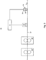
- Fig. 1 shows by way of example and simplified schematic representation of a printing press 01 with preferably several printing units 02; 03; 04.
- the printing units 02; 03; 04 of this printing machine 01 prints at least one printing unit 04 in a direct printing process with a printing formless printing device, in particular with an inkjet system 06.
- Another printing unit 02; 03 of this printing press 01 prints z. B. in an offset printing process or in a gravure printing process.
- Belonging to this printing press 01 printing units 02; 03; 04 jointly print one, ie the same guided by the printing press 01 substrate 07, wherein the substrate 07 z. B. is formed as a material web or as a printed sheet, in particular as a sequence of printed sheets.
- the printing machine 01 z. B.
- the printing machine 01 is z. B. used in newspaper printing or commercial printing or packaging printing.
- the substrate 07 is z. B. of paper, plastic, metal or a multi-component material, eg. Example of a coated carrier material or of a material having a multilayer structure, in which the layers in particular consist of different materials.
- At least two of the belonging to this printing machine 01 printing units 02; 03; 04, one of which is formed as the printing unit 04 with an inkjet system 06, are arranged in the relevant printing press 01 along a path provided for the printing material 07 transport path T in a row successively.
- the inkjet system 06 in question is designed in such a way that this inkjet system 06 prints information changing or at least changeable in the current printing process to a target surface 08 provided on the printing substrate 07.
- a plurality of inkjet systems 06 z. B. along a Traverse be arranged side by side, which are controlled so that they each print different respectively in the current printing process respectively changing or at least changeable information each on their respective assigned on the substrate 07 intended target area 08.
- Each of the inkjet systems 06 usually prints monochrome, ie prints only a single ink.
- the z. B. formed as a material web substrate 07 is in a running printing process at a speed of z. B. transported up to 15 m / s along its intended transport path T through the printing press 01.
- Fig. 2 can be removed, has to be printed in the printing substrate 07 a transversely directed to its transport T T width B07, wherein the respective target surface 08, which is provided for the pressure to be executed by the respective inkjet system 06, each one transverse to that for the Substrate 07 provided transport path T directed width B08, wherein the width B08 of the respective target surface 08 is in each case smaller than z. B. one half of the width B07 of the printing substrate 07.
- the respective target surface 08 is z. B. arranged in or on a printed image 09 of a printed copy to be produced in the current printing process, wherein the respective print image 09 on the substrate 07 in a z. B.
- the respective target area 08 is also z. B. formed as a rectangular field and has dimensions of the order of z. B. 100 mm by 75 mm.
- the respective width B08 of the respective target surface 08 is in each case also smaller than the width B09 of the respective target surface 08 respectively assigned print image 09.
- the relevant print image 09 which is associated with the target surface 08 for the impression of variable information, is preferably of at least one the other z. B. in offset printing or gravure printing printing units 02; 03 printed.
- the variable information in the relevant print job is z.
- Example a coding which is added during the printing process a print image 09 of a printed copy in order to make the relevant printed copy distinguishable from the other printed copies of the relevant print job and thereby to individualize.
- This variable information and / or an indication of the position of the intended for this information target area 08 on the substrate 07 are z. B. from a cooperating with a control unit 11 database, in particular the control unit 11 and database of a production planning system, and / or the control unit 11 of the press 01 controlling control station z. B. provided to the respective inkjet system 06.
- the coding and thus the variable information has z. B. an address and / or numbering or is designed as an address and / or numbering. With a printed address, the printed copy in question is personalized and can z.
- variable information is from a database associated with the one in question Inkjet system 06 controlling unit 11, provided in the form of a systematic or stochastic coding, this database preferably belongs to that production planning system which controls the process to be executed by the printing press 01, ie the respective processed by the printing machine 01 print job.
- a production planning system is generally understood to mean a computer-aided production planning and control system, which is used for operational planning and control of the production process, for.
- a production planning system supports the processes and processes of a product delivery, ie the production and delivery of a product, eg B. a printed product. With the help of a production planning system, orders are processed, products are configured, produced and delivered.
- the at least one successively arranged, designed as an inkjet system 06 printing unit 04 in the printing machine 01 is fixedly arranged by the respective inkjet system 06 z. B. with a frame of this printing press 01 is firmly connected.
- 03 is a printing material 07 in its position, in particular transversely to its intended transport path T adjusting positioning device 12 is provided, wherein a position of the pressure in the current printing process changing or at least variable information provided target area 08 by positioning the printing material 07 by means of Positioning device 12 is set relative to the fixedly arranged inkjet system 06 or at least adjustable.
- the positioning device 12 z. B. as a web guide or as a web aligner and / or as an arrangement of arranged in the transport path T of the printing material 07 turning bars and / or formed as a Beyakstoffsp Son adopted and / or as a transversely to the transport path T of the printing material 07 adjustable former 19.
- the Positioning device 12 is z. B. in one of the printing machine 01 associated, various processing stages having machine unit arranged.
- the printing material 07 positioning positioning 12 is z. B. controlled by the cooperating with the database control unit 11 or at least controllable.
- a printing material spreading device ie a spreading the printing substrate 07 device usually has a longitudinal cutting device with which formed as a material web 07 is cut along its transport path T for the production of at least two partial webs, then these sub-webs laterally by an array of turner bars, ie transverse to their respective transport direction are offset, so that forms a gap between two adjacent sub-webs by their spaced-apart arrangement.
- the sub-webs can be merged after their separation and optionally after their different processing in the current printing process, if necessary, again to a common strand.
- Fig. 3 also shows only schematically another example in which the at least one formed as an inkjet system 06 printing unit 04 in contrast to the embodiment according to the Fig. 1 is not stationary in the printing press 01, but the respective inkjet system 06 is in the printing machine 01 at least in the direction transverse to the intended for the substrate 07 Transportweg T by means of a remotely operated or at least remotely controllable actuator 13 differently positioned, in particular relative to at least one reference edge of the printing material 07 adjustable to different positions, wherein the relevant reference edge of the printing material 07 z. B. is directed longitudinally to the provided for this substrate 07 transport path T.
- a relevant feature here, already in connection with the Fig. 1 or 2 is described in the Fig. 3 with the same reference number as in FIG Fig. 1 characterized.
- At least one mark 14 is present, preferably on the substrate 07 both in the direction transverse to the provided for this substrate 07 Transportweg T and along each of several brands 14 available, these at least one mark 14 in a running printing process or production process is detected by a detection device 16 or at least detectable.
- the at least one mark 14 is z. B. from a printing unit 02; 03, which is arranged upstream of the inkjet system 06 in the direction of the transport path T provided for the printing substrate 07, has been printed on the printing material 07.
- This at least one mark 14 is z. B. a part of the upstream of the printing unit 02; 03 created print image 09 or at least this printed image 09 assigned.
- the at least one arranged on the substrate 07 mark 14 detection device 16 is z. B.
- This particular optical detection device 16 has z. B. a camera or this detection device 16 uses at least one camera, preferably a semiconductor camera.
- the detection device 16 is z. B. connected to the inkjet system 06 in its current position adjusting device 13 and / or with the printing material 07 positioning positioning device 12, in particular connected by data technology.
- the adjusting device 13 or the positioning device 12 each have z. B. an electric or pneumatic drive 26, by means of which the inkjet system 06 or the substrate 07 at least in the direction transverse to the transport path T provided for the substrate 07 z. B.
- the position of the inkjet system 06 which can be positioned differently at least in the direction transverse to the transport path T provided for the printing substrate 07, and / or the printing material 07 having the relevant target surface 08 are thus based on the at least one in the current Production process of the detection device 16 detected mark 14 set or at least adjustable by the position, the z. B.
- the pressure of changing in the current printing process or at least changeable information on the target surface 08 is to be taken, depending on the at least one detected by the detection device 16 position or position of at least one arranged on the substrate 07 mark 14 is set relative to the position of the intended for the printing of changing in the current printing process or at least variable information target surface 08 is or, wherein the position or position of the respective brand 14 and the target Position of the target surface 08 in a fixed, ie at least during the current setting and printing process immutable relationship to each other.
- the current position of the inkjet system 06 is or will z. B.
- the adjusting device 13 such that the relevant detected by the detection device 16 mark 14 and the current position of the inkjet system concerned 06 z. B. aligned, that are in a same track along the path provided for the substrate 07 transport path T.
- the printing material 07 having the relevant target surface 08 is / are set by the positioning device 12 connected to the detection device 16 as a function of the registered mark 14 relative to the relevant inkjet system 06.
- a printing position and / or a printing time of the inkjet system 06 in question relative to a position of the printing process that is changing in the current printing process or at least changeable information provided target area 08 is set or at least adjustable.
- the printing position is the position from which the inkjet system 06 carries out its printing operation with respect to the printing material 07 guided by the printing press 01, wherein this position z.
- B. either by positioning the entire subject inkjet system 06 relative to the target surface 08 on the Substrate 07 or by a selection of at least one of preferably several in the relevant, in the printing machine 01 z.
- nozzles is set or is adjustable, from these nozzles each drop of ink or ink are ejected.
- the printing time ie, the respective time for the ejection of printing ink or ink, from one or more of these nozzles is preferably also based on the at least one mark 14 detected by the detecting device 16 in the current printing process relevant inkjet system 06 is set relative to a position of the intended for the printing of changing in the current printing process or at least changeable information target surface 08 or at least adjustable.
- a nozzle bar 213 arranged in the inkjet system 06 has several rows of nozzles along the transport path T of the printing material 07, these nozzles being selectively set at least with regard to their respective printing time on the basis of the at least one mark 14 detected by the detection device 16 during the current printing process or at least adjustable. On the drops of a printing ink or ink ejecting nozzles of the respective inkjet system 06 will be later in particular in connection with the Fig. 12 to 14 received.
- a method for printing information which changes or at least changes information in a running printing process results on a target surface 08 provided on a substrate 07, wherein at least one brand 14 arranged on the substrate 07 and detected by a detection device 16 in the current printing process a printing position and / or a printing time of an inkjet system 06 relative to a position of the pressure for the in the current printing process changing or at least changeable information provided target area is set 08, wherein the at least one arranged on the substrate 07 mark 14 is detected by a formed as part of a cutting register control device and / or a color register control device detection device 16.
- the at least one mark 14 arranged on the printing substrate 07 is optically detected.
- the printing position based on the at least one detected in the current printing process by the detection device 16 mark 14 or the inkjet system 06 and / or the substrate 07 are moved at least in one direction transverse to a transport path T provided for the substrate 07. Furthermore, to set the printing position, at least one of a plurality of nozzles provided in the inkjet system 06 concerned can be selected on the basis of the at least one marker 14 detected in the current printing process. The at least one selected nozzle ejects drops of a printing ink or ink. To set the printing time based on the at least one in the current printing process detected by the detection device 16 mark 14 z. B.
- variable information is preferably added to a printed image 09 arranged on the printing substrate 07 in the form of a coding, the coding making the relevant printed image 09 distinguishable from other printed images 09.
- first advantageous arrangements of the inkjet system 06 in question are described in a web press to that position, in particular of the respective inkjet system 06 in the respective web press current, ie for printing in the current printing process changing or at least changeable information on the target area 08 is to be taken, relative to the position of the pressure in the to set current printing process changing or at least changeable information provided target area 08.
- formed as a material web substrate 07 passes through in a web press after its printing with print images 09 along its intended transport path T z. B. in a stand-alone machine unit diverse processing stages to which z. B.
- the material web which may have been cut longitudinally into a plurality of partial webs, is preferably fed to the folding apparatus 21 via the former 19.
- the web or its partial webs was or were at the former 19 z. B. folded into a strand or z. B. by means of the turning tool 17 placed on each other, said strand is then fed to the folding apparatus 21.
- a transverse cutting of the strand concerned and at least the generation of a transverse fold In an advantageous embodiment -.
- the folder 21 also has means for generating a third fold, z. B. a second Lijnsfalzes on.
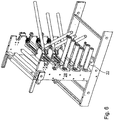
- the Fig. 5 shows a front view of the in the Fig. 4 exemplified further processing stages.
- the turning plant 17 are downstream of the maximum number of partial webs corresponding number of deflectors, z. B. arranged downstream of at least one designed as a Bay window device 22 deflecting device.
- the respective bay window device 22 has at least one deflection roller whose axis of rotation runs parallel to the transport path T of the printing material 07 through the printing press.
- the Bay window device 22 is z. B. arranged on an outer side of a turning bars supporting frame 28 or side frame 28.
- the respective bay window device 22 in each case two deflection rollers, which are viewed in a direction perpendicular to the transport path T of the printing substrate 07 viewed by the printing machine from each other. These guide rollers are viewed in the vertical direction so at a height arranged so that they at least overlap in a horizontal plane, that is, they are arranged substantially at a same height.
- Fig. 6 shows the Bay Window device 22 by way of example in a perspective view. Further details of a Bay Window device 22 are z.
- that printing unit 04 which prints the changing or at least changeable information on the substrate 07, ie in particular the inkjet system concerned 06, z. B.
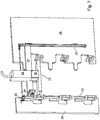
- Fig. 7 shows an enlarged detail of the Fig. 7
- the z. B. trained as inkjet system 06 printing unit 04 is preferably formed height adjustable on the Bay window device 22.
- the inkjet system 06 in question can be adjusted in height over several levels of the turning unit 17 in particular.
- a pair of vertically opposed guide rails 23 and a first drive 24 is provided, said first drive 24 z. B. is designed as a hand crank or as a remotely operable actuator.
- preferably another z is also z. B.
- Fig. 9 shows a side view of the disposed on the Bay window device 22 inkjet system 06.
- Fig. 3 illustrated embodiment with the arrangement of the respective inkjet system 06 at the Bay Window device 22 according to the Fig. 7 to 9 combined or at least combinable.
- the position of the inkjet system 06 concerned is then set on the bay window device 22 by controlling the second drive 26, which is preferably designed as a remotely operable actuator, in the manner described above or at least adjustable.
- the second drive 26 is z. B. to the remote-controlled or at least remotely actuable actuating device 13.
- a further advantageous variant of the invention combines that in the Fig. 1 illustrated embodiment with the arrangement of the particular designed as an inkjet system 06 printing unit 04 at the Bay Window device 22.
- the respective inkjet system 06 is fixedly disposed on the Bay window device 22, z. B. in the area of the center M of the width B07 of the guided through the Bay window device 22 substrate 07.
- the Bay Window device 22 upstream in the transport direction of the substrate 07 is then formed as a web of substrate 07 in its position across provided for its intended transport path T adjusting positioning device 12, said positioning device 12 z. B. as a web guide and / or as an arrangement of the transport path T of the printing substrate 07 arranged turning bars and / or is designed as a printing material spreader.
- This positioning device 12 is - as already described - z. B. by the control unit 11 in response to an indication of the position of the target surface 08, which is provided on the substrate 07 for the changing or at least changeable information, controlled or at least controllable.
- a further advantageous arrangement provides that the respective inkjet system 06 directly on the former 19, ie at a small distance of z. B. less than 2 m, or is located immediately above the former 19, this inkjet system 06 is operated such that in the current printing process changing or at least changeable information is printed on the target surface 08 provided on the substrate 07 while the relevant target surface 08 of this printing material 07 runs or is guided over the former 19.
- either this former 19 or the respective inkjet system 06 are each adjustable transversely to the transport path T of the printing material 07.
- This arrangement has the advantage that the printing material 07 has a firm support while the information changing or at least variable in the current printing process is printed on the target surface 08 provided on the printing substrate 07.
- Fig. 10 shows a schematic diagram of this arrangement.
- the former 19 is in connection with the Fig. 1 explained way z. B. adjusted by a control command of the control unit 11 transversely to the transport path T of the printing substrate 07 or at least adjustable, so that the former 19 performs the function of the positioning device 12.
- the respective inkjet system 06 is in connection with the Fig. 3 explained manner by the adjusting device 13 z. B. based on at least one detected in the current production process by a detection device 16, arranged on the substrate 07 mark 14 transversely to the transport path T of the printing substrate 07 adjusted or at least adjustable.
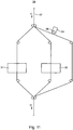
- the z. B. formed as an inkjet system 06 printing unit 04 is arranged in conjunction with a strand subassembly 29, ie in one of the branches of the strand subassembly 29, as exemplified in the Fig. 11 is shown in a schematic diagram.
- the strand subassembly 29 is arranged in the transport direction of the printing material 07, in particular after the former 19 and before the folder 21, ie on the transport path T between the former 19 and the folder 21.
- a strand of the substrate 07 consisting of several sub-webs and produced in a same printing process is separated along its transport path T into several sub-strands or even into individual sub-webs, wherein at least some of these different partial strands or partial webs are each subjected to a different further processing in their respective branch of the strand subassembly 29. It can be provided that the various partial strands or partial webs subjected to different further processing are subsequently brought together again to form a common strand.
- the various further processing can in processing steps such. B. stapling and / or gluing and / or punching and / or perforating, wherein in the respective branches of the strand subassembly 29 corresponding means for carrying out said processing steps are arranged.
- a stapling device 31 and a perforating device 32 are shown in two different partial strands.
- the stapling device 31 and / or the perforating device 32 can also be arranged on a bay window device 22 if the respective sub-strand or the respective at least one sub-web is guided via a bay window device 22 in the corresponding branch of the strand subassembly 29.
- the inkjet system 06 in question can be arranged stationarily or at least transversely to the respective transport path T variably positionable.
- the substrate 07 by means of a arranged in the respective branch positioning device 12 in conjunction with the Fig. 1 explained way z. B. by a control command of the control unit 11 transversely to the transport path T of the printing substrate 07 adjusted or at least adjustable.
- the relevant printing unit 04, z. B. inkjet system 06 is arranged variable position, the inkjet system 06 in question is in connection with the Fig.
- an inkjet system 06 is arranged in several branches of the strand subassembly 29, each of which prints in the current printing process changing or at least changeable information on the respective target surface 08 on the substrate (07).
- inkjet systems 06 z. B. operated such that they each print different respectively in the current printing process changing or at least changeable information in each case to their respective assigned on the substrate 07 provided target area 08.
- the information changing in the current printing process or at least changeable information and / or the position of the intended target for this information 08 on the substrate 07 preferably by the control unit 11, in particular a production planning system and / or the control unit 11 of the Printing machine 01 controlling console provided to the respective inkjet system 06.
- the respective installation locations relevant arrangements of the respective inkjet system 06 which prints the changing in the current printing process or at least changeable information on the provided on the substrate 07 target area 08, so are either with a fixed or with a variable location arrangement of the relevant Inkjet system 06 combined, in which case, depending on the choice made, either the respective inkjet system 06 is positioned relative to the target surface 08 provided on the substrate 07 or this target surface 08 to the respective inkjet system 06.
- a printing machine 01 with preferably a plurality of jointly printing substrate 07 printing units 02; 03; 04, wherein at least one of these printing units 04 a changing in a running printing process or at least changeable information on a particular provided on the substrate 07 target surface 08 prints, wherein in the transport direction of the printing material 07 with respect to the transport T at a short distance of a few meters, z. B.
- the substrate 07 in its position transverse to its intended transport path T adjusting positioning device 12 is provided, wherein a position the relevant target area 08, which is provided for the printing of changing in the current printing process or at least changeable information on the substrate 07, in the current printing process by means of the positioning 12 made or at least vorrisebare positioning of the printing material 07 relative to the relevant changing or at least changeable information printing unit 04 is set or at least adjustable, wherein the printing material 07 adjusting in position positioning 12 by a control unit 11 in response to an indication of the position of the target area 08, which is provided on the substrate 07 for the changing or at least changeable information, is controlled or at least controllable, this information for the respective changing or at least variable, to be printed on the substrate 07 information in a cooperating with the control unit 11 Database is stored and provided by this database.
- the printing units 02; 03 which are not used to print the information changing or at least changeable in the current printing process to the target area 08 provided on the substrate 07, ie a printing unit 02 different from the printing group 04; 03, each print the substrate 07 in a digital printing process, ie, perform the printing process without a fixed printing form.
- a digital printing machine formed printing machine 01 is described below with reference to the Fig. 12 to 14 described in more detail.
- the respective installation locations relevant arrangements of that printing unit 04 with the inkjet system 06, which changes in the current printing process or at least variable information printed on the printing substrate 07 target surface 08 prints, and optionally the stationary or spatially variable arrangement of the respective inkjet system 06 are also combined with the design of the printing machine 01 as a digital printing machine or at least combinable.
- the printing machine 01 embodied as a digital printing machine has at least one printing material source 100, at least one first printing unit 200, preferably at least one first dryer 301, preferably at least one second printing unit 400 and preferably at least one second dryer 331 and preferably at least one post-processing device 500.
- This printing machine 01 is also preferably designed as an inkjet printing machine 01.
- the digital printing machine is designed as a web-fed printing machine, more preferably as a roll-type inkjet printing machine.
- This printing press 01 is designed, for example, as a rotary printing press, for example as a rotary rotary printing press, in particular a rotary rotary inkjet printing press.
- the printing material source 100 is designed as a roll-off device 100.
- the printing material source 100 is designed as a sheet feeder.
- At least one printing material 07 is preferably aligned in the printing material source 100, preferably at least with respect to one edge of this printing material 07.
- at least one web-shaped printing material 07 ie a printing material web, for example a paper web or a textile web or a film, for example one Plastic film or a metal foil unwound from a Beyakstoffrolle 101 and preferably aligned with respect to their edges in an axial direction A.
- the axial direction A is preferably a direction parallel to a rotation axis 111 of a printing material roll 101 and / or at least one central cylinder 201; 401 extends.
- a transport path T of the at least one printing substrate 07 and, in particular, the printing material web run following the at least one printing material source 100, preferably through the at least one first Printing unit 200, where the printing substrate 07 and in particular the printing material preferably by at least one ink at least one side and preferably in conjunction with the at least one second printing unit 400 preferably on two sides with a printed image 09 is provided.
- the transport path T of the printing material 07 and in particular of the printing material web preferably passes through the at least one first dryer 301 in order to dry the applied printing ink.
- Printing ink is to be understood in the preceding text and generally below as meaning a coating composition, in particular also a lacquer.
- the at least one first dryer 301 is part of a dryer unit 300.
- the printing substrate 07 and in particular the printing material web is preferably at least a post-processing device 500 is supplied and further processed there.
- the at least one post-processing device 500 is designed, for example, as at least one folding device 500 and / or as a take-up device 500 and / or as at least one planned delivery 500.
- the printing material 07 which is preferably printed on two sides, is preferably further processed into individual printed products.
- At least the first dryer 301 and / or after the at least one first dryer 301 is preferably at least the second printing unit 400 and / or after the at least one first printing unit 200 along the transport path T of the printing substrate 07 and in particular of the printing substrate by the printing press 01
- the at least one second printing unit 400 preferably the at least one second dryer 331 and / or after the at least one second dryer 331 preferably arranged the at least one post-processing device 500.
- Bescherstoffrollen 101 which are preferably used in the Rollenabspulvorraum 100 used, preferably each have a sleeve on which the web-shaped substrate 07 is wound for use in the web printing press.
- the printing material web preferably has a width of 700 mm to 2000 mm, but may also have an arbitrarily smaller or preferably larger width.
- Bescherstoffrolle 101 is rotatably arranged.
- the Rollenabspulvorraum 100 is designed to accommodate a Beyakstoffrolle 101 suitably, thus has only one storage position for a Beyakstoffrolle 101.
- the Rollenabspulvortechnisch 100 is formed as a roll changer 100 and has storage positions for at least two Betikstofrollollen 101.
- the reel changer 100 is designed such that it enables a flying reel change, that is to connect a first printing material web of a currently processed printing substrate 101 with a second substrate web of a subsequently to be processed Beyakstoffrolle 101, while both the currently processed Beyakstoffrolle 101, as well as the following rotating printing substrate roll 101.
- a working width of the printing press 01 is a dimension which preferably extends orthogonally to the intended transport path T of the printing material 07 through the at least one first printing unit 200, more preferably in the axial direction A.
- the working width of the printing press 01 preferably corresponds to a maximum width may have a substrate 07 in order to be processed with the printing press 01, so a maximum processable with the printing press 01 Betigstoffbach.
- the roll-off device 100 preferably has at least one roll holding device 103 per storage position, which is designed, for example, as a clamping device 103 and / or as a clamping device 103.
- the at least one roller holding device 103 preferably serves to rotatably fasten at least one printing material roller 101.
- the at least one roller holding device 103 preferably has at least one drive motor 104.
- the Rollenabspulvorides 100 along the transport path T of the printing material after the roll holding device 103 preferably at a dancer lever 121 deflectably arranged dancer roller 113 and / or a first Brukantenausrichter 114 and /, a formed by a pull roller 118 and a Switzerlandpresseur 117 feed nip 119 and a pull-in unit 139 having first measuring device 141, which is designed as first measuring roller 141, in particular pull-in measuring roller 141.
- This tension roller 118 preferably has its own drive motor 146, designed as a traction drive motor 146, which is preferably provided with a machine control, for example a drive motor 146. B. the control unit 11 is connected.
- the draw roller 118 preferably represents at least one second motor-driven rotary body 118.
- a web tension is adjustable and can be kept within limits and / or the web tension is preferably kept within limits.
- the Rollenabspulvorraum 100 an adhesive and cutting device by means of a role change flying, d. H. without stopping the printing material can bestatten.
- the web 139 is preferably arranged.
- at least the draw roller 118 is preferably arranged, with which the pull press 117 is preferably arranged together forming the feed nip 119.
- the intake nip 119 serves to regulate a web tension and / or a transport of the printing material 07.
- the web tension can be measured by means of the at least one first measuring device 141 designed as a first measuring roller 141.
- the at least one first measuring device 141 designed as a first measuring roller 141 is preferably arranged in front of the drawing-in gap 119 in the transport direction of the printing material web.
- the wrap angle is the angle measured in the circumferential direction of a cylinder jacket surface of the first central cylinder 201, along which the printing material 07 and in particular the printing material web is in contact with the first central cylinder 201. Accordingly, at least 50% and more preferably at least 75% of the cylinder jacket surface of the first central cylinder 201 are in contact with the printing material web in the circumferential direction when printing.
- a partial surface of a cylinder jacket surface of the at least one first central cylinder 201 provided as the contact surface between the at least one first central cylinder 201 and the substrate material preferably embodied as printing material web has the wrap angle around the at least one first central cylinder 201, which is preferably at least 180 ° and more preferably at least 270 °.
- first printing material preparation device 202 or web preparation device 202 is arranged to act on the printing substrate web and / or aligned with the intended transport path T of the printing substrate web.
- the first printing material preparation device 202 is assigned to at least one first side and preferably both sides of the printing substrate web and in particular aligned and / or capable of acting on at least this first side of the printing substrate web and preferably on both sides of the printing substrate web.
- the transport path T of the printing material web between the first Brukantenausrichter 114 and the at least one first central cylinder 201 of the draw roller 118 and the Switzerlandpresseur 117 formed feed nip 119 is arranged.
- the at least one first substrate preparation device 202 is arranged in a preferred embodiment along the transport path T of the printing substrate after the feed nip 119 and before the first central cylinder 201 acting on the substrate web and / or aligned with the transport path T of the printing substrate.
- the at least one first substrate preparation device 202 is preferably designed as at least one substrate cleaning device 202 or web cleaning device 202.
- the at least one printing material preparation device 202 is designed as at least one coating device 202, in particular for water-based coating compositions. Such a coating serves, for example, a primer.
- the at least one substrate preparation device 202 is designed as at least one corona device 202 and / or discharge device 202 for corona treatment of the printing material 07.
- a roller 203 of the first printing unit 200 designed as a first deflecting roller 203 is arranged parallel to the first central cylinder 201 with respect to its axis of rotation.
- This first deflecting roller 203 is preferably arranged at a distance from the first central cylinder 201.
- the printing material web preferably wraps around a part of the first deflecting roller 203 and is deflected by the latter in such a way that the transport path T of the printing material web in the first intermediate space 204 is both tangential to the first deflecting roller 203 and tangential to the first central cylinder 201.
- a lateral surface of the deflection roller 203 preferably consists of a comparatively inelastic material, more preferably a metal, even more preferably steel or aluminum.
- At least one first cylinder 206 designed as the first impression roller 206 is arranged in the first pressure unit 200.
- the first impression roller 206 preferably has a lateral surface which consists of an elastic material, for example an elastomer.
- the first impression roller 206 is preferably adjustable by means of a Anstellantriebs to the first central cylinder 201 and / or disposed thereof ab plausible.
- the first impression roller 206 In a state applied to the first central cylinder 201, the first impression roller 206 preferably forms a first impression gap 209 together with the first central cylinder 201.
- the printing material web preferably passes through the first impression gap 209 during printing operation.
- the printing material web is preferably applied flatly and more preferably in a clear and known position to the first central cylinder 201.
- the axis of rotation of the first impression roller 206 is below the axis of rotation 207 of the first Central cylinder 201 arranged.
- the first central cylinder 201 preferably has its own, the first central cylinder 201 associated with the first drive motor 208, which is preferably designed as an electric motor 208 and is further preferably formed as a direct drive 208 and / or individual drive 208 of the first central cylinder 201.
- a direct drive 208 is to be understood as meaning a drive motor 208 which is in torque transmitting and / or transferable connection with the at least one first central cylinder 201 without the interposition of further rotational bodies in contact with the printing substrate 07.
- a single drive 208 is to be understood as a drive motor 208, which is designed as the drive motor 208 exclusively of the at least one first central cylinder 201.
- the first drive motor 208 of the first central cylinder 201 preferably has at least one permanent magnet, which is more preferably part of a rotor of the first drive motor 208 of the first central cylinder 201.
- a first rotation angle sensor is preferably arranged which measures a rotational angle position of the first drive motor 208 and / or the first central cylinder 201 itself measuring and / or measurable and to a higher-level machine control is designed to send and / or send.
- the first rotation angle sensor is designed, for example, as a rotary encoder or absolute value encoder. With such a rotation angle sensor is a rotational position of the first drive motor 208 and / or preferably a rotational position of the first central cylinder 201 preferably by means of the higher-level machine control, z. B. the control unit 11, absolutely determinable.
- the first drive motor 208 of the first central cylinder 201 is connected in such a circuit with the machine control that the machine control at any time on the basis of given by the machine control to the first drive motor 208 of the first central cylinder 201 target data to a rotational position of the first drive motor 208 via the Rotational position of the first Drive motor 208 and thus at the same time the rotational position of the first central cylinder 201 is informed.
- a region of the machine control which prescribes the rotational angle position or rotational position of the first central cylinder 201 and / or the first drive motor 201 is preferably connected directly to a region of the machine control system which controls at least one print head 212 of the first printing unit 200, in particular without an interposed sensor.
- the at least one first printing unit 211 is preferably arranged in the direction of rotation of the first central cylinder 201 and thus along the transport path T of the printing material web after the first impression roller 206 preferably acting on the at least one first central cylinder 201 and / or operative and / or aligned and / or alignable.
- the at least one first printing unit 211 is designed as a first inkjet printing unit 211 and is also called a first inkjet printing unit 211.
- the first printing unit 211 preferably has at least one nozzle bar 213 and preferably a plurality of nozzle bars 213.
- the at least one first printing unit 211 and thus the at least one first printing unit 200 preferably has the at least one first printing head 212, which is designed as an inkjet printing head 212.
- the at least one nozzle bar 213 in each case has at least one print head 212 and preferably in each case a plurality of print heads 212.
- Each printhead 212 preferably has a plurality of nozzles from which ink droplets are ejected and / or ejected.
- a nozzle bar 213 is a component which preferably extends over at least 80% and more preferably at least 100% of the working width of the printing machine 01 and serves as a carrier of the at least one print head 212.
- an axial length of the bale of the at least one first central cylinder 201 is at least as large as the working width of the printing press 01.
- a single or a plurality of nozzle bars 213 per printing unit 211 are arranged.
- Each nozzle is preferably a clearly defined target area on the direction A of the width of the printing material web and preferably on the direction A in particular the Rotary axis 207 associated with the at least one first central cylinder 201.
- each target area of a nozzle in particular with respect to the circumferential direction of the at least one first central cylinder 201, is clearly defined at least in the printing operation.
- a target area of a nozzle is that, in particular, substantially rectilinear space area which extends in a direction of ejection of this nozzle from this nozzle.
- the at least one first nozzle bar 213 preferably extends orthogonally to the transport path T of the printing material 07 over the working width of the printing press 01.
- the at least one nozzle bar 213 preferably has at least one row of nozzles.
- the at least one row of nozzles viewed in the axial direction A, preferably has nozzle openings at regular intervals over the entire working width of the printing machine 01 and / or width of the bale of the at least one first central cylinder 201.
- a single continuous print head 212 is arranged for this purpose, which extends in the axial direction A over the entire working width of the printing press 01 and / or the entire width of the bale of the at least one first central cylinder 201.
- the at least one row of nozzles is preferably formed as at least one linear, over the entire width of the printing material in the axial direction A extending juxtaposition of individual nozzles.
- a plurality of print heads 212 are arranged next to each other on the at least one nozzle bar 213 in the axial direction A.
- print heads 212 are not provided with nozzles up to an edge of their housing, preferably at least two, and more preferably exactly two, rows of print heads 212 extending in the axial direction A are arranged offset relative to one another in the circumferential direction of the first central cylinder 201, preferably so in that in axial direction A successive printheads 212 preferably belong alternately to one of the at least two rows of printheads 212, preferably always alternating first and second of two rows of printheads 212. Two such rows of printheads 212 form a double row of Printheads 212.
- the at least one row of nozzles is preferably not formed as a single linear juxtaposition of nozzles, but results as a sum of several individual, more preferably two, circumferentially offset from each other arranged juxtaposition of nozzles.
- a print head 212 has a plurality of nozzles, then all target areas of the nozzles of this print head 212 together form a working area of this print head 212.
- Working areas of print heads 212 of a nozzle bar 213 and in particular a double row of print heads 212 adjoin one another and / or overlap in the axial direction A. seen in the axial direction A. In this way, even when the print head 212 is not continuous in the axial direction A, target areas of nozzles of the at least one nozzle bar 213 and / or in particular of each double row of print heads 212 are located at regular and preferably periodic intervals in the axial direction A.
- an entire working area of the at least one nozzle bar 213 preferably extends over at least 90% and more preferably 100% of the working width of the printing machine 01 and / or the entire width of the bale of the at least one first central cylinder 201 in the axial direction A. or both sides with respect to the axial direction A, there may be a narrow area of the printing material web and / or the bale of the first central cylinder 201, which does not belong to the working area of the nozzle bars 213.
- An entire working area of the at least one nozzle bar 213 is preferably composed of all working areas of print heads 212 of this at least one nozzle bar and is preferably composed of all target areas of nozzles of these print heads 212 of this at least one nozzle bar 213.
- an entire working area of a double row of print heads 212 in the axial direction A corresponds to the working area of the at least one nozzle bar 213.
- each print head 212 has a plurality of nozzles, which are further preferably arranged in a matrix of a plurality of rows in the axial direction A and / or a plurality of columns, preferably in the circumferential direction of the at least one first central cylinder 201, such columns preferably further obliquely to the circumferential direction are arranged extending, for example, to increase a resolution of a print image 09.
- a plurality of rows of print heads 212 in a direction orthogonal to the axial direction A, in particular in the transport direction along the transport path T of the printing substrate 07 and / or in the circumferential direction relative to the at least one central cylinder 201, a plurality of rows of print heads 212, more preferably four double rows and even more preferably eight double rows of print heads 212 arranged one after the other. More preferably, at least in the printing operation in the circumferential direction with respect to the at least one first central cylinder 201 a plurality of rows of printheads 212, more preferably four double rows and still more preferably eight double rows of printheads 212 arranged successively aligned on the at least one first central cylinder 201.
- the print heads 212 are preferably aligned, at least in the printing operation, such that the nozzles of each print head 212 point in the radial direction toward the cylinder jacket surface of the at least one first central cylinder 201. Deviations from radial directions within a tolerance range of preferably not more than 10 ° and more preferably not more than 5 ° are to be considered essentially radial directions. This means that the at least one print head 212 aligned with the lateral surface of the at least one first central cylinder 201 is aligned with the rotational surface 207 of the at least one first central cylinder 201 in a radial direction on the lateral surface of the at least one first central cylinder 201.
- this radial direction is a radial direction relative to the axis of rotation 207 of the at least one first central cylinder 201.
- Each double row of printheads 212 is preferably an ink of a particular color assigned and / or assignable, for example in each case one of the colors black, cyan, yellow and magenta or a lacquer, for example a clearcoat.
- the corresponding inkjet printing unit 211 is preferably formed as a four-color printing unit 211 and allows a one-sided four-color printing of the printing material web. It is also possible to print fewer or more different colors with a printing unit 211, for example additional spot colors.
- correspondingly more or fewer printheads 212 and / or double rows of printheads 212 are arranged within this corresponding printing unit 211.
- a plurality of rows of printheads 212, more preferably four double rows, and more preferably eight double rows of printheads 212 are sequentially aligned on at least one surface of at least one transfer body, eg, at least one transfer cylinder and / or at least one transfer belt.
- the at least one print head 212 preferably operates to generate ink droplets by the drop-on-demand method, in which ink droplets are generated selectively as needed.
- at least one piezo element is used per nozzle, which can reduce a volume filled with ink at high speed by a certain amount when a voltage is applied. This displaces ink which is ejected through a nozzle connected to the volume filled with ink and forms at least one ink droplet.
- By applying different voltages to the piezoelectric element is influenced on a travel of the piezoelectric element and thus the reduction of the volume and thus the size of the ink drops.
- a drop deflection after ejection from the corresponding nozzle is not necessary since it is possible to set a target position of the respective ink droplet on the moving substrate web with respect to the circumferential direction of the at least one first central cylinder 201 solely by an emission timing of the respective one Drop of ink and a rotational speed of the first central cylinder 201 and / or determined by the rotational position of the first central cylinder 201.
- By individual control of each nozzle ink drops are transferred from the at least one print head 212 to the substrate web only at selected times and at selected locations.
- a comparison with actual data of the rotational position of the first drive motor 208 is preferably not necessary and preferably does not take place.
- An exact and constant position or position of the printing material web relative to the at least one first central cylinder 201 is therefore of great importance for a passport-compatible and / or register-compatible printed image 09.
- the nozzles of the at least one print head 212 are arranged such that a
- the distance between the nozzles and the printing material web arranged on the cylinder jacket surface of the at least one first central cylinder 201 is preferably between 0.5 mm and 5 mm and more preferably between 1 mm and 1.5 mm.
- the high angular resolution and / or the high sampling frequency of the rotation angle sensor and / or the high accuracy of the predetermined by the machine control and processed by the first drive motor 208 of the first central cylinder 201 target data to the rotational position of the first drive motor 208 of the first central cylinder 201 allows a very accurate Orientation and / or knowledge of the position or position of the printing substrate 02 relative to the nozzles and their target areas.
- a drop flight time between the nozzles and the printing material web 02 is known, for example, by a teaching process and / or by the known distance between the nozzles and the printing material web and a known drop speed. From the rotational angle position of the at least one first central cylinder 201 and / or the first drive 208 of the at least one first central cylinder 201, the rotational speed of the at least one first central cylinder 201 and the droplet flight time, an ideal time for ejection of a respective droplet is determined, so that a passer-like and / or register-compliant imaging of the substrate web is achieved.
- At least one sensor designed as a first print image sensor is arranged, more preferably at a location along the transport path T of the printing material web after the first printing group 211.
- the at least one first print image sensor is designed for example as a first line camera or as a first area camera.
- the at least one first print image sensor is designed, for example, as at least one CCD sensor and / or as at least one CMOS sensor.
- a location of pixels formed by ink droplets originating from a respective first printhead 212 is preferably compared to a location of pixels formed by ink droplets emerging from respective second, circumferential, directions At least a first central cylinder 201 according to the respective first printhead 212 lying printhead 212 originate. This is preferably done independently of whether these each process first and second, in the circumferential direction of the at least one first central cylinder 201 successive and / or acting print heads 212 a same or a different ink. It is monitored a vote of the layers of originating from different printheads 212 print images 09. For the same inks, register-based joining of partial images is monitored. For different inks, a register or color register is monitored. A quality control of the print image 09 is preferably also carried out with the measured values of the at least one print image sensor.
- all printheads 212 are stationary. Thereby a permanent passport-oriented and / or register-oriented alignment of all nozzles is ensured.
- Different situations are conceivable in which a movement of the print heads 212 is necessary.
- a first such situation is a flying roll change or generally a roll change with gluing process.
- a substrate web is connected by means of an adhesive strip with another printing material web. This results in a connection point, which must pass through the entire transport path T of the printing substrate.
- This joint has a thickness, ie a smallest dimension, which is greater than a thickness of the printing material web. In essence, the joint is as thick as two substrates and the adhesive strip together.
- the at least one nozzle bar 213 is therefore movable in at least one direction relative to the axis of rotation 207 of the at least one first central cylinder 201. In this way, the distance can be sufficiently increased, but must be subsequently reduced accordingly again.
- a second such situation results, for example, in the maintenance and / or cleaning of at least one of the print heads 212.
- the print heads 212 are preferably fastened individually to the at least one nozzle bar 213 and individually detachable from the at least one nozzle bar 213. This allows individual printheads 212 to be maintained and / or cleaned and / or replaced.
- nozzle bars 213 which are movable relative to one another are arranged, minimal misalignment of the nozzle bars 213 with one another may occur when at least one nozzle bar 213 is returned to a pressure position. An alignment requirement can thus occur, in particular all print heads 212 of a nozzle bar 213 to printheads 212 other nozzle bars 213.
- a new and / or reordering printhead 212 attached to the at least one nozzle bar 213, to which at least one other printhead 212 is attached so does not necessarily mean but at most coincidentally an exactly matching orientation of this new and / or reassembled printhead 212 to the at least one printhead 212 already attached, in the circumferential direction and / or in the axial direction A with respect to the at least one first central cylinder 201.
- an alignment requirement may arise, in particular a single printhead 212 to another Printheads 212 of the same nozzle bar 213 and / or other nozzle bar 213.
- At least one sensor detects a position of the target area of at least one new and / or re-arranged printhead 212 relative to a position of the target area of at least one printhead 212 already attached.
- An installation position of the at least one newly and / or re-arranged printhead 212 in the circumferential direction relative to the at least one a first central cylinder 201 can be compensated by controlling the nozzles of this print head 212, preferably analogous to the already described adaptation of printheads 212 different double rows of printheads 212.
- An installation position of the at least one new and / or re-arranged printhead 212 in the axial direction A with respect the at least one first central cylinder 201 is compensated by means of at least one adjusting mechanism.
- several print heads 212 each have their own adjustment mechanism, more preferably, all print heads 212 each have their own adjustment mechanism.
- the printing press 01 has at least one supply system for coating means, in particular ink supply system.
- a plurality of print heads 212 for example a plurality of print heads 212 of a common nozzle bar 213, in particular several or more preferably all print heads 212 each of a double row of print heads 212, a common supply system for coating agent.
- This common supply system preferably has at least one normal supply.
- At least one first liquid line or color line per print head 212 is connected to the at least one normal supply.
- the at least one normal supply via at least one supply line and at least one derivative with at least one and preferably at least one same Buffer connected.
- the normal supply preferably has at least one printing operation and more preferably a continuous level of deviations lying within a narrow tolerance range. This constant level can be achieved, for example, by means of a preferably passive overflow drain and an influx of printing ink.
- the normal supply and / or the at least one discharge at least one preferably passive overflow drain, the outflow side is preferably connected to the at least one intermediate memory and / or arranged connectable.
- at least one preferably designed as a check valve valve is disposed within the at least one supply line and / or within the at least one derivative.
- At least one first liquid pump is preferably arranged in the at least one feed line.
- a controlled and / or regulated normal pressure prevails in the normal supply, which is further preferably controlled and / or regulated relative to an ambient pressure.
- ink is pumped from the buffer into the normal supply by at least one pump.
- at least one volume provided as the first gas space is arranged in the at least one normal reserve.
- the at least one first gas space is preferably connected via at least one first gas line with at least one first gas pump.
- the at least one buffer is connected to at least one buffer memory, more preferably via at least one suction line.
- ink is conveyed by the relative negative pressure from the buffer memory in the buffer.
- a plurality of print heads 212 for example a plurality of print heads 212 of a common nozzle bar 213, in particular a plurality or more preferably all print heads 212 each of a double row of print heads 212, have a common power supply system.
- at least one common power line of the power supply extends within the respective at least one nozzle bar over at least 50%, more preferably at least 75% and even more preferably at least 90% of a working area of the respective at least one nozzle bar 213 in the axial direction A and / or The working width of the printing press 01.
- each printhead 212 of this respective at least one nozzle bar 213 each has at least one own voltage line, which is connected to this common power line of the power supply.
- Each printhead 212 of each respective at least one nozzle bar 213 preferably has at least one own data line which is connected to a computing unit which is outside the working area of the respective at least one nozzle bar 213 with respect to the axial direction A and / or outside each with respect to the axial direction A.
- substrate 07 provided transport path T of the printing press 01 is arranged.
- at least one data line per print head 212 of this at least one nozzle bar 213 runs parallel to one another.
- At least one nozzle cleaning device is arranged, which has at least one row of washing nozzles and / or brushes and / or pullers.
- the printing material web After the printing material web has passed the at least one first printing unit 200, the printing material web is transported further along its transport path T and preferably fed to the at least one first dryer 301 of the at least one dryer unit 300.
- the first side of the printing material web printed by the at least one first printing unit 200 preferably lies between a last contact point of the printing substrate web with the at least one first central cylinder 201 of the at least one a first printing unit 200 and an area of action of the at least one first dryer 301 with no component of the web press in contact.
- the second, in particular not printed by the first printing unit 200 the at least one first central cylinder 201 of the at least one first printing unit 200 contacting side of the printing substrate between the last contact point of the printing substrate with the first central cylinder 201 of the at least one first printing unit 200 and the Einwirk Scheme of the at least one first dryer 301 with at least one deflecting roller 214 of the at least one first printing unit 200 and / or with at least one deflecting roller 312 of the at least one first dryer 301 in contact.
- At least one third measuring device 214 which is also preferably designed as a third measuring roller 214, is preferably arranged. This third measuring device 214 is used to measure the web tension. More preferably, the at least one deflecting roller 214 of the first printing unit 200 is identical to the third measuring device 214 designed as the third measuring roller 214.
- the at least one first dryer 301 is preferably designed as an infrared radiation dryer 301.
- the at least one first dryer 301 preferably has at least one radiation source 302, which is preferably designed as an infrared radiation source 302.
- a radiation source 302, preferably infrared radiation source 302 is a device by means of which targeted electrical energy is converted into radiation, preferably infrared radiation, and / or is convertible and is directed onto the printing material web and / or can be directed.
- the at least one radiation source 302 preferably has a defined area of action.
- the exposure region of a radiation source 302 is in each case the region which contains all the points which, in particular, can be connected in a straight line directly or via reflectors to the radiation source 302 without interruption.
- the area of action of the at least one first dryer 301 is composed of the areas of action of all the radiation sources 302 of the at least one first dryer 301.
- the area of action of the at least one first dryer 301 preferably comprises at least one radiation source 302 to one of the at least one radiation source 302 nearest part of the transport path T of the printing substrate.
- Air is introduced into the interior of the at least one first dryer 301 through at least one ventilation opening.
- water to be removed and / or solvent of the printing inks is removed by the infrared radiation from the printing material web and taken up by the introduced air. This air is then removed through at least one vent opening from the at least one first dryer 301.
- the intended transport path T for the printing material 07 by the at least one first dryer 301 at least two sections, each extending in directions with vertical components, more preferably with larger vertical than optional horizontal components.
- the intended transport path T of the printing substrate 07 extends along one section at least with a component in the vertical direction upwards.
- the intended transport path T of the printing substrate 07 runs along the other portion at least with a component in the vertical direction downwards.
- the one portion and the other portion of the proposed transport path T by at least one provided connector of the proposed transport path T are interconnected.
- the at least one connecting piece extends in a direction with a horizontal component, more preferably with a larger horizontal than optionally present vertical component.
- the at least one dryer 301 can preferably be made particularly compact.
- At least one first cooling device 303 is preferably arranged in the transport direction of the printing material web after the action region of the at least one radiation source 302 of the at least one first dryer 301.
- the at least one first cooling device 303 preferably has at least one first cooling roller 304 and preferably a first, at least a first cooling roller 304 engageable and / or salarieddewalzenpresseur 306 and preferably at least one, to the at least one first cooling roller 304 engageable and / or employed Anlenkwalze 307; 308 up.
- One of the at least one first cooling roller 304 associated first designed as a first cooling roller drive motor 311 drive motor 311 and the firstdewalzenpresseur 306 are preferably part of a web tension control, so the web tension is arranged regulating and preferably for this purpose at least partially and / or temporarily with the higher-level machine control, z , B. the control unit 11 connected.
- the at least one first cooling roller 304 preferably represents at least a fourth motor-driven rotational body 304.
- the printing material web wraps and preferably contacts along its transport path T the at least one first cooling roller 304 with a wrap angle of preferably at least 180 ° and more preferably at least 270 °.
- the first cooling roll press 306 preferably forms with the at least one first cooling roll 304 a first cooling roll gap 309, in which the printing material web is preferably arranged and / or which preferably passes through the printing material web. In this case, the printing material web is pressed by the cooling roller press 306 to the at least one first cooling roller 304.
- the at least one first cooling roller 304 of the at least one first cooling device 303 is preferably designed as a cooling roller 304 through which a coolant flows.
- At least one second printing unit 400 is preferably arranged along the transport path T of the printing material web after the at least one first cooling device 303.
- at least one second printing unit 400 is arranged along the transport path T of the printing material web, preferably immediately before the at least one second printing unit 400 and preferably after the at least one first dryer 301 and in particular after the at least one first printing unit 200, at least one second web edge aligner is arranged, which is preferably manually or driven controllable and / or is designed adjustable.
- the at least one second printing unit 400 is constructed analogously to the first printing unit 200.
- the second printing unit 400 has a second central cylinder 401 or short central cylinder 401, which in the printing operation of the printing substrate is wrapped, also with a wrap angle of preferably at least 180 ° and more preferably at least 270 °.
- the second central cylinder 401 preferably represents a fifth motor-driven rotary body 401.
- the second central cylinder 401 of the second pressure unit 400 preferably has a rotational direction which is opposite to a direction of rotation of the at least one first central cylinder 201.
- a second printing substrate cleaning device 402 or web cleaning device 402 is preferably arranged to act on the printing substrate web.
- the transport path T of the printing material web through the at least one second printing unit 400 extends analogously to the transport path T through the at least one first printing unit 200.
- the printing material web preferably wraps around a part of a second deflecting roller 403 and is deflected by the latter in such a way that the transport path T of the printing substrate web in the second intermediate space 404 both tangential to the second guide roller 403 and tangent to the second central cylinder 401 extends.
- at least one cylinder 406 designed as a second impression roller 406 is arranged in the second printing unit 400.
- the second impression roller 406 is preferably constructed and arranged analogously to the first impression roller 206, in particular with regard to its mobility and a second impression gap 409.
- the second central cylinder 401 is preferably arranged and constructed analogously to the first central cylinder 201, in particular with respect to a second drive motor 408 of the second Central cylinder 401 and a corresponding preferably arranged second rotation angle sensor, which is a rotational angular position of the second drive motor 408 and / or the second central cylinder 401 itself measuring and / or measuring and sending to the higher-level machine control and / or sendable.
- At least one second printing unit 411 which is designed as an inkjet printing unit 411 or inkjet printing unit 411, is preferred Direction of rotation of the second central cylinder 401 and thus arranged along the transport path T of the printing substrate after the second impression roller 406 aligned on the second central cylinder 401.
- the at least one second printing unit 411 of the at least one second printing unit 400 is preferably identical to the at least one first printing unit 211 of the at least one first printing unit 200, in particular with regard to at least one nozzle bar 413, at least one print head 412 designed as an inkjet printhead 412 and its arrangement in double rows, the execution and resolution of the printing process, the arrangement, alignment and control of the nozzles and the mobility and adjustability of the at least one nozzle bar 413 and the at least one printhead 412 by means of at least one adjusting mechanism with a corresponding electric motor.
- An analogous protective cover and / or cleaning device is also preferably arranged.
- a correct alignment of the printheads 412 of the at least one second printing unit 400 is preferably checked by at least one sensor detecting a printed print image 09 and the machine controller evaluating this printed image 09.
- This at least one sensor is preferably at least one second printed image sensor which is designed analogously to the at least one first printed image sensor.
- the at least one second printing unit 411 is designed as a four-color printing unit 411.
- At least one second dryer 331 is arranged after the at least one second printing unit 400. After the printing material web has passed the at least one second printing unit 400, the printing material web is transported further along its transport path T and preferably fed to the at least one second dryer 331 of the at least one dryer unit 300.
- the at least one second dryer 331 is preferably constructed analogously to the at least one first dryer 301.
- the at least one first dryer 301 and the at least one second dryer 331 are components of the at least one dryer unit 300.
- the second side of the printing material web printed by the at least one second printing unit 400 is between a last one Touching the substrate web with the second central cylinder 401 of the at least one second printing unit 400 and a Einwirk Scheme the at least one second dryer 301 with no part of the web printing machine in contact.
- At least one deflecting roller 414 of the second printing unit 400 is preferably arranged. This at least one deflecting roller 414 is preferably designed as a fifth measuring device 414, in particular a fifth measuring roller 414.
- the construction of the at least one second dryer 331 is similar to the construction of the at least one first dryer 301, in particular with regard to a transport path T provided for the printing substrate and / or a design as a flow dryer 331 and / or radiation dryer 331 and / or hot air dryer 331 and / or infrared radiation dryer 331 and / or UV radiation dryer 331.
- the at least one second dryer 331 preferably has at least one second cooling roller 334, which more preferably represents at least a sixth motor-driven rotary body 334.
- the second cooling roller 334 is driven and / or driven by means of a second cooling roller drive 341.
- the at least one second dryer 331 is constructed essentially and more preferably completely symmetrically relative to the at least one first dryer 301 with respect to the described components.
- the at least one second dryer 331 is preferably part of the same dryer unit 300 as the at least one first dryer 301 and is further preferably arranged in a same housing 329.
- the dryer unit 300 and thus preferably the at least one first dryer 301 and the at least one second dryer 331 are preferably arranged between the at least one first printing unit 200 and the at least one second printing unit 400.
- the at least one pull-out roller 501 preferably has its own pull-out roller drive 504 trained drive motor 504 on.
- the at least one pull-out roller 501 preferably represents at least a seventh motor-driven rotary body 501.
- the at least one pull-out roller 501 preferably forms, together with a pull-out press 502 set and / or adjustable against the at least one pull-out roller 501, a pull-out gap 503 in which the printing material web is clamped and through the printing material is conveyed.
- the pull-out gap 503 is preferably used to control a web tension and / or a transport of the printing material web.
- At least one remoistening device is arranged, which preferably causes excessive moisture loss of the printing material web due to Treatment by the dryer unit 300 compensates.
- At least one post-processing device 500 is arranged, which is preferably designed as a folding device 500 and / or a sheet cutter 500 and / or a plan display 500 or is formed as a winding device 500.
- the printing material web is preferably folded and / or cut and / or stapled and / or sorted and / or enveloped and / or shipped and / or wound up.
- the printing press 01 is designed as a roller-type rotary ink-jet printing machine 01, and at least one transfer body with the at least one first central printing cylinder 201 is arranged to form a transfer nip. Then, preferably, the at least one print head 212 is aligned with the at least one transfer body.
Description
Die Erfindung betrifft eine Druckmaschine mit mehreren gemeinsam einen Bedruckstoff bedruckenden Druckwerken gemäß Anspruch 1.The invention relates to a printing machine with a plurality of printing units jointly printed on a printing material according to claim 1.
Durch die
Durch die
Durch die
Durch die
Durch die
Durch die
Durch die
Durch die
Der Erfindung liegt die Aufgabe zugrunde, eine Druckmaschine mit mehreren gemeinsam einen Bedruckstoff bedruckenden Druckwerken zu schaffen, wobei zumindest eines dieser Druckwerke einen Eindruck einer sich in einem laufenden Druckprozess verändernden oder zumindest veränderbaren Information an einer auf dem Bedruckstoff vorgesehenen Zielfläche positionsrichtig ausführt.The invention has for its object to provide a printing machine with a plurality of jointly printing a substrate printing units, wherein at least one This printing performs an impression of a changing in a running printing process or at least changeable information on a target surface provided on the substrate in the correct position.
Die Aufgabe wird erfindungsgemäß durch die Merkmale des Anspruches 1 gelöst.The object is achieved by the features of claim 1.
Die mit der Erfindung erzielbaren Vorteile bestehen insbesondere darin, dass in einer Druckmaschine mit mehreren gemeinsam einen Bedruckstoff bedruckenden Druckwerken zumindest eines dieser Druckwerke, welches vorzugsweise als ein Inkjetsystem ausgebildet ist, einen Eindruck einer sich in einem laufenden Druckprozess verändernden oder zumindest veränderbaren Information an einer auf dem Bedruckstoff vorgesehenen Zielfläche positionsrichtig ausführt.The achievable with the present invention consist in particular in that in a printing machine with a plurality of jointly printing a substrate printing units at least one of these printing units, which preferably as an inkjet system is designed to execute an impression of a changing in a running printing process or at least changeable information on a target surface provided on the substrate in the correct position.
Ausführungsbeispiele der Erfindung sind in den Zeichnungen dargestellt und werden im Folgenden näher beschrieben.Embodiments of the invention are illustrated in the drawings and will be described in more detail below.
Es zeigen:
-
Fig. 1 eine Druckmaschine mit einem ortsfesten Inkjetsystem; -
Fig. 2 einen Bedruckstoff mit Druckbildern, Zielflächen und Marken; -
Fig. 3 eine Druckmaschine mit einem während eines laufenden Druckprozesses positionierbaren Inkjetsystem; -
Fig. 4 diverse Weiterverarbeitungsstufen einer Rollendruckmaschine mit einer Längsschneideinrichtung und einem Wendewerk; -
Fig. 5 eine Vorderansicht der in derFig. 4 dargestellten Weiterverarbeitungsstufen; -
Fig. 6 eine perspektivische Darstellung einer Bay-Window-Einrichtung; -
Fig. 7 eine Anordnung eines Inkjetsystems auf einer Bay-Window-Einrichtung; -
Fig. 8 eine Ausschnittsvergrößerung aus derFig. 7 ; -
Fig. 9 eine Seitenansicht des an der Bay-Window-Einrichtung angeordneten Inkjetsystems; -
Fig. 10 eine Anordnung des Inkjetsystems an einem Falztrichter; -
Fig. 11 eine Anordnung des Inkjetsystems in einem Zweig einer Strangteileinrichtung; -
Fig. 12 eine schematische Darstellung eines Beispiels für eine Digitaldruckmaschine; -
Fig. 13 eine schematische Darstellung einer Digitaldruckmaschine mit einer alternativen Führung der Materialbahn; -
Fig. 14 eine schematische Darstellung eines Teils einer Druckeinheit mit einer Doppelreihe von Druckköpfen.
-
Fig. 1 a printing machine with a fixed inkjet system; -
Fig. 2 a substrate with printed images, target areas and marks; -
Fig. 3 a printing machine with an inkjet system positionable during a running printing process; -
Fig. 4 various further processing steps of a web-fed printing press with a longitudinal cutting device and a turning device; -
Fig. 5 a front view of the in theFig. 4 represented further processing stages; -
Fig. 6 a perspective view of a Bay Window device; -
Fig. 7 an arrangement of an inkjet system on a bay window device; -
Fig. 8 an excerpt from theFig. 7 ; -
Fig. 9 a side view of the disposed on the Bay window device inkjet system; -
Fig. 10 an arrangement of the inkjet system on a former; -
Fig. 11 an arrangement of the inkjet system in a branch of a strand subassembly; -
Fig. 12 a schematic representation of an example of a digital printing machine; -
Fig. 13 a schematic representation of a digital printing machine with an alternative guidance of the material web; -
Fig. 14 a schematic representation of a portion of a printing unit with a double row of printheads.
Wie der
In einem in der
Verfahrensmäßig formuliert ergibt sich ein Verfahren zum Drucken einer sich in einem laufenden Druckprozess verändernden oder zumindest veränderbaren Information auf eine auf einem Bedruckstoff 07 vorgesehene Zielfläche 08, wobei anhand mindestens einer auf dem Bedruckstoff 07 angeordneten und in dem laufenden Druckprozess von einer Erfassungseinrichtung 16 erfassten Marke 14 eine Druckposition und/oder ein Druckzeitpunkt eines Inkjetsystems 06 relativ zu einer Position der für den Druck der sich in dem laufenden Druckprozess verändernden oder zumindest veränderbaren Information vorgesehenen Zielfläche 08 eingestellt wird, wobei die mindestens eine auf dem Bedruckstoff 07 angeordnete Marke 14 von einer als ein Teil einer Schnittregisterregeleinrichtung und/oder einer Farbregisterregeleinrichtung ausgebildeten Erfassungseinrichtung 16 erfasst wird. Dabei wird die mindestens eine auf dem Bedruckstoff 07 angeordnete Marke 14 optisch erfasst. Zur Einstellung der Druckposition anhand der mindestens einen in dem laufenden Druckprozess von der Erfassungseinrichtung 16 erfassten Marke 14 wird bzw. werden das Inkjetsystem 06 und/oder der Bedruckstoff 07 zumindest in einer Richtung quer zu einem für den Bedruckstoff 07 vorgesehenen Transportweg T bewegt. Des Weiteren kann zur Einstellung der Druckposition anhand der mindestens einen in dem laufenden Druckprozess von der Erfassungseinrichtung 16 erfassten Marke 14 mindestens eine von mehreren in dem betreffenden Inkjetsystem 06 vorgesehenen Düsen ausgewählt werden, wobei die mindestens eine ausgewählte Düse jeweils Tropfen einer Druckfarbe oder Tinte ausstößt. Zur Einstellung des Druckzeitpunktes anhand der mindestens einen in dem laufenden Druckprozess von der Erfassungseinrichtung 16 erfassten Marke 14 wird z. B. aus in einem Düsenbalken 213 längs zum Transportweg T des Bedruckstoffs 07 in mehreren Reihen angeordneten Düsen mindestens eine dieser Düsen ausgewählt. Die variable Information wird während des Druckprozesses einem auf dem Bedruckstoff 07 angeordneten Druckbild 09 vorzugsweise in Form einer Codierung hinzugefügt, wobei die Codierung das betreffende Druckbild 09 von anderen Druckbildern 09 unterscheidbar macht.Formulated in terms of the method, a method for printing information which changes or at least changes information in a running printing process results on a
Im Folgenden werden zunächst beispielhaft vorteilhafte Anordnungen des betreffenden Inkjetsystems 06 in einer Rollendruckmaschine beschrieben, um diejenige Position, die insbesondere von dem betreffenden Inkjetsystem 06 in der betreffenden Rollendruckmaschine aktuell, d. h. zum Drucken der sich in dem laufenden Druckprozess verändernden oder zumindest veränderbaren Information auf der Zielfläche 08 eingenommen werden soll, relativ zu der Position der für den Druck der sich in dem laufenden Druckprozess verändernden oder zumindest veränderbaren Information vorgesehenen Zielfläche 08 einzustellen. Wie in der
Die
Eine weitere vorteilhafte Variante der Erfindung kombiniert das in der
Es kann auch vorgesehen sein, dass an der Bay-Window-Einrichtung 22 z. B. zusammen mit dem zuvor beschriebenen Inkjetsystem 06 eine gleichfalls z. B. höhenverstellbare Perforiereinrichtung 32 angeordnet ist. Ferner kann in Verbindung mit einem andernorts in der Druckmaschine 01 oder in deren Nachverarbeitung angeordneten Inkjetsystem 06 vorgesehen sein, dass an der Bay-Window-Einrichtung 22 eine Perforiereinrichtung 32 angeordnet ist.It can also be provided that at the Bay Window device 22 z. B. together with the previously described
Eine weitere vorteilhafte Anordnung sieht vor, dass das betreffende Inkjetsystem 06 unmittelbar am Falztrichter 19, d. h. in einem geringen Abstand von z. B. weniger als 2 m, oder unmittelbar oberhalb des Falztrichters 19 angeordnet ist, wobei dieses Inkjetsystem 06 derart betrieben ist, dass die sich in dem laufenden Druckprozess verändernde oder zumindest veränderbare Information auf die auf dem Bedruckstoff 07 vorgesehene Zielfläche 08 gedruckt wird, während die betreffende Zielfläche 08 dieses Bedruckstoffes 07 über den Falztrichter 19 läuft bzw. geführt ist. Dabei sind in einer vorteilhaften Ausbildung entweder dieser Falztrichter 19 oder das betreffende Inkjetsystem 06 jeweils quer zum Transportweg T des Bedruckstoffes 07 verstellbar. Diese Anordnung hat den Vorteil, dass der Bedruckstoff 07 eine feste Auflage hat, während die sich in dem laufenden Druckprozess verändernde oder zumindest veränderbare Information auf die auf dem Bedruckstoff 07 vorgesehene Zielfläche 08 gedruckt wird.
Des Weiteren kann vorgesehen sein, dass das betreffende z. B. als Inkjetsystem 06 ausgebildete Druckwerk 04 in Verbindung mit einer Strangteileinrichtung 29 angeordnet ist, d. h. in einem der Zweige der Strangteileinrichtung 29, wie es beispielhaft in der
Die zuvor beschriebenen, die jeweiligen Einbauorte betreffenden Anordnungen des betreffenden Inkjetsystems 06, welches die sich in dem laufenden Druckprozess verändernde oder zumindest veränderbare Information auf die auf dem Bedruckstoff 07 vorgesehene Zielfläche 08 druckt, sind also wahlweise mit einer ortsfesten oder mit einer ortsvariablen Anordnung des betreffenden Inkjetsystems 06 kombinierbar, wobei dann je nach getroffener Wahl entweder das betreffende Inkjetsystem 06 relativ zu der auf dem Bedruckstoff 07 vorgesehenen Zielfläche 08 positioniert wird oder diese Zielfläche 08 zu dem betreffenden Inkjetsystem 06.The above-described, the respective installation locations relevant arrangements of the
Mithin ergibt sich eine Druckmaschine 01 mit vorzugsweise mehreren gemeinsam einen Bedruckstoff 07 bedruckenden Druckwerken 02; 03; 04, wobei zumindest eines dieser Druckwerke 04 eine sich in einem laufenden Druckprozess verändernde oder zumindest veränderbare Information auf eine bestimmte auf dem Bedruckstoff 07 vorgesehene Zielfläche 08 druckt, wobei in Transportrichtung des Bedruckstoffes 07 mit Bezug auf dessen Transportweg T in einem kurzen Abstand von höchstens wenigen Metern, z. B. von weniger als 3 m, vor dem betreffenden Druckwerk 04, das die sich verändernde oder zumindest veränderbare Information auf den Bedruckstoff 07 druckt, eine den Bedruckstoff 07 in seiner Position quer zu seinem vorgesehenen Transportweg T einstellende Positioniereinrichtung 12 vorgesehen ist, wobei eine Position der betreffenden Zielfläche 08, die für den Druck der sich in dem laufenden Druckprozess verändernden oder zumindest veränderbaren Information auf dem Bedruckstoff 07 vorgesehen ist, in dem laufenden Druckprozess durch eine mittels der Positioniereinrichtung 12 vorgenommene oder zumindest vornehmbare Positionierung des Bedruckstoffes 07 relativ zu dem betreffenden die sich verändernde oder zumindest veränderbare Information druckenden Druckwerk 04 eingestellt oder zumindest einstellbar ist, wobei die den Bedruckstoff 07 in seiner Position einstellende Positioniereinrichtung 12 von einer Steuereinheit 11 in Abhängigkeit von einer Angabe zur Position der Zielfläche 08, die auf dem Bedruckstoff 07 für die sich verändernde oder zumindest veränderbare Information vorgesehen ist, gesteuert oder zumindest steuerbar ist, wobei diese Angabe für die jeweilige sich verändernde oder zumindest veränderbare, auf den Bedruckstoff 07 zu druckende Information in einer mit der Steuereinheit 11 zusammenwirkenden Datenbank gespeichert und von dieser Datenbank bereitgestellt ist.Thus results in a
In einer weiteren Ausgestaltung der Druckmaschine 01 kann vorgesehen sein, dass auch die Druckwerke 02; 03, die nicht dazu verwendet werden, die sich in dem laufenden Druckprozess verändernde oder zumindest veränderbare Information auf die auf dem Bedruckstoff 07 vorgesehene Zielfläche 08 zu drucken, d. h. ein vom Druckwerk 04 verschiedenes Druckwerk 02; 03, jeweils in einem Digitaldruckverfahren den Bedruckstoff 07 bedrucken, d. h. den Druckprozess ohne feste Druckform ausführen. Eine solche als eine Digitaldruckmaschine ausgebildete Druckmaschine 01 wird im Folgenden anhand der
Die als eine Digitaldruckmaschine ausgebildete Druckmaschine 01 weist zumindest eine Bedruckstoffquelle 100, zumindest eine erste Druckeinheit 200, bevorzugt zumindest einen ersten Trockner 301, bevorzugt zumindest eine zweite Druckeinheit 400 und bevorzugt zumindest einen zweiten Trockner 331 und bevorzugt zumindest eine Nachbearbeitungsvorrichtung 500 auf. Diese Druckmaschine 01 ist zudem bevorzugt als Tintenstrahldruckmaschine 01 ausgebildet. Bevorzugt ist die Digitaldruckmaschine als eine Rollendruckmaschine ausgebildet, weiter bevorzugt als eine Rollen-Tintenstrahldruckmaschine. Diese Druckmaschine 01 ist beispielsweise als Rotationsdruckmaschine ausgebildet, beispielsweise als Rollen-Rotationsdruckmaschine, insbesondere Rollen-Rotations-Tintenstrahldruckmaschine. Im Fall einer Rollen-Druckmaschine ist die Bedruckstoffquelle 100 als Rollenabspulvorrichtung 100 ausgebildet. Im Fall einer Bogendruckmaschine oder Bogen-Rotationsdruckmaschine ist die Bedruckstoffquelle 100 als Bogenanleger ausgebildet. In der Bedruckstoffquelle 100 wird bevorzugt zumindest ein Bedruckstoff 07 ausgerichtet, bevorzugt zumindest bezüglich einer Kante dieses Bedruckstoffs 07. In der Rollenabspulvorrichtung 100 einer Rollendruckmaschine wird zumindest ein bahnförmiger Bedruckstoff 07, also eine Bedruckstoffbahn, beispielsweise eine Papierbahn oder eine Textilbahn oder eine Folie, beispielsweise eine Kunststofffolie oder eine Metallfolie von einer Bedruckstoffrolle 101 abgespult und bevorzugt bezüglich ihrer Kanten in einer axialen Richtung A ausgerichtet. Die axiale Richtung A ist bevorzugt eine Richtung, die sich parallel zu einer Rotationsachse 111 einer Bedruckstoffrolle 101 und/oder zumindest eines Zentralzylinders 201; 401 erstreckt. Ein Transportweg T des zumindest einen Bedruckstoffs 07 und insbesondere die Bedruckstoffbahn verlaufen im Anschluss an die zumindest eine Bedruckstoffquelle 100 bevorzugt durch die zumindest eine erste Druckeinheit 200, wo der Bedruckstoff 07 und insbesondere die Bedruckstoffbahn bevorzugt mittels zumindest einer Druckfarbe zumindest einseitig und bevorzugt in Verbindung mit der zumindest einen zweiten Druckeinheit 400 bevorzugt zweiseitig mit einem Druckbild 09 versehen wird.The
Nach einem Passieren der zumindest einen ersten Druckeinheit 200 durchläuft der Transportweg T des Bedruckstoffs 07 und insbesondere der Bedruckstoffbahn bevorzugt den zumindest einen ersten Trockner 301, um die aufgetragene Druckfarbe zu trocknen. Unter Druckfarbe ist im Vorangegangenen und im Folgenden allgemein ein Beschichtungsmittel zu verstehen, insbesondere auch ein Lack. Bevorzugt ist der zumindest eine erste Trockner 301 Bestandteil einer Trocknereinheit 300. Nach dem Passieren des zumindest einen ersten Trockners 301 und bevorzugt der zumindest einen zweiten Druckeinheit 400 und/oder des zumindest einen zweiten Trockners 331 wird der Bedruckstoff 07 und insbesondere die Bedruckstoffbahn bevorzugt der zumindest einen Nachbearbeitungsvorrichtung 500 zugeführt und dort weiter verarbeitet. Die zumindest eine Nachbearbeitungsvorrichtung 500 ist beispielsweise als zumindest eine Falzvorrichtung 500 und/oder als eine Aufwickelvorrichtung 500 und/oder als zumindest eine Planauslage 500 ausgebildet. In der zumindest einen Falzvorrichtung 500 wird der bevorzugt zweiseitig bedruckte Bedruckstoff 07 bevorzugt zu einzelnen Druckprodukten weiterverarbeitet.After passing through the at least one
Bevorzugt ist entlang des Transportwegs T des Bedruckstoffs 07 und insbesondere der Bedruckstoffbahn durch die Druckmaschine 01 nach der zumindest einen ersten Druckeinheit 200 bevorzugt zumindest der erste Trockner 301 und/oder nach dem zumindest einen ersten Trockner 301 bevorzugt zumindest die zweite Druckeinheit 400 und/oder nach der zumindest einen zweiten Druckeinheit 400 bevorzugt der zumindest eine zweite Trockner 331 und/oder nach dem zumindest einen zweiten Trockner 331 bevorzugt die zumindest eine Nachbearbeitungsvorrichtung 500 angeordnet. Dadurch ist sichergestellt, dass ein beidseitiger Bedruck des Bedruckstoffs 02 und insbesondere der Bedruckstoffbahn in hoher Qualität ermöglicht wird.Preferably, at least the
Im Folgenden wird eine Rollen-Druckmaschine näher beschrieben. Entsprechende Einzelheiten lassen sich aber genauso auf andere Druckmaschinen 01, beispielsweise Bogen-Druckmaschinen übertragen, sofern sie dazu nicht im Widerspruch stehen. Bedruckstoffrollen 101, die bevorzugt in der Rollenabspulvorrichtung 100 zum Einsatz kommen, weisen bevorzugt jeweils eine Hülse auf, auf die der bahnförmige Bedruckstoff 07 für einen Einsatz in der Rollendruckmaschine aufgewickelt ist. Die Bedruckstoffbahn weist bevorzugt eine Breite von 700 mm bis 2000 mm auf, kann aber auch eine beliebig kleinere oder bevorzugt größere Breite aufweisen. In der Rollenabspulvorrichtung 100 ist zumindest eine Bedruckstoffrolle 101 rotierbar angeordnet. In einer bevorzugten Ausführungsform ist die Rollenabspulvorrichtung 100 für die Aufnahme einer Bedruckstoffrolle 101 geeignet ausgebildet, weist also nur eine Speicherposition für eine Bedruckstoffrolle 101 auf. In einer anderen Ausführungsform ist die Rollenabspulvorrichtung 100 als Rollenwechsler 100 ausgebildet und weist Speicherpositionen für zumindest zwei Bedruckstoffrollen 101 auf. Bevorzugt ist der Rollenwechsler 100 derart ausgebildet, dass er einen fliegenden Rollenwechsel ermöglicht, also ein Verbinden einer ersten Bedruckstoffbahn einer aktuell verarbeiteten Bedruckstoffrolle 101 mit einer zweiten Bedruckstoffbahn einer nachfolgend zu verarbeitenden Bedruckstoffrolle 101, während sowohl die aktuell verarbeitete Bedruckstoffrolle 101, als auch die nachfolgend zu verarbeitende Bedruckstoffrolle 101 rotieren.In the following, a roll printing machine will be described in more detail. Corresponding details can, however, also be transferred to
Eine Arbeitsbreite der Druckmaschine 01 ist eine Abmessung, die sich bevorzugt orthogonal zu dem vorgesehenen Transportweg T des Bedruckstoffs 07 durch die zumindest eine erste Druckeinheit 200 erstreckt, weiter bevorzugt in der axialen Richtung A. Die Arbeitsbreite der Druckmaschine 01 entspricht bevorzugt einer maximalen Breite, die ein Bedruckstoff 07 aufweisen darf, um noch mit der Druckmaschine 01 verarbeitet werden zu können, also einer maximalen mit der Druckmaschine 01 verarbeitbaren Bedruckstoffbreite.A working width of the
Die Rollenabspulvorrichtung 100 weist bevorzugt je Speicherposition zumindest eine Rollenhaltevorrichtung 103 auf, die beispielsweise als Spannvorrichtung 103 und/oder als Klemmvorrichtung 103 ausgebildet ist. Bevorzugt stellt die zumindest eine Rollenhaltevorrichtung 103 zumindest einen ersten motorgetriebenen Rotationskörper 103 dar. Die zumindest eine Rollenhaltevorrichtung 103 dient einer rotierbaren Befestigung zumindest einer Bedruckstoffrolle 101. Die zumindest eine Rollenhaltevorrichtung 103 weist bevorzugt zumindest einen Antriebsmotor 104 auf.The roll-off
Bevorzugt weist die Rollenabspulvorrichtung 100 entlang des Transportwegs T der Bedruckstoffbahn nach der Rollenhaltevorrichtung 103 eine bevorzugt an einem Tänzerhebel 121 auslenkbar angeordnete Tänzerwalze 113 und/oder einen ersten Bahnkantenausrichter 114 und/oder ein, einen von einer Zugwalze 118 und einem Zugpresseur 117 gebildeten Einzugspalt 119 und eine als erste Messwalze 141, insbesondere Einzugmesswalze 141 ausgebildete erste Messeinrichtung 141 aufweisendes Einzugwerk 139 auf. Diese Zugwalze 118 weist bevorzugt einen eigenen, als Zugantriebsmotor 146 ausgebildeten Antriebsmotor 146 auf, der bevorzugt mit einer Maschinensteuerung, z. B. der Steuereinheit 11 verbunden ist. Die Zugwalze 118 stellt bevorzugt zumindest einen zweiten motorgetriebenen Rotationskörper 118 dar. Mittels der Tänzerwalze 113 ist eine Bahnspannung einstellbar und in Grenzen haltbar und/oder wird die Bahnspannung bevorzugt in Grenzen gehalten. Gegebenenfalls weist die Rollenabspulvorrichtung 100 eine Klebe- und Schneideinrichtung auf, mittels der ein Rollenwechsel fliegend, d. h. ohne Stillstand der Bedruckstoffbahn vonstattengehen kann.Preferably, the
Dem ersten Bahnkantenausrichter 114 nachfolgend ist bevorzugt das Einzugwerk 139 angeordnet. Als Bestandteil des Einzugwerks 139 ist bevorzugt zumindest die Zugwalze 118 angeordnet, mit der bevorzugt der Zugpresseur 117 zusammen den Einzugspalt 119 bildend angeordnet ist. Der Einzugspalt 119 dient einer Regelung einer Bahnspannung und/oder einem Transport des Bedruckstoffs 07. Bevorzugt ist mittels der zumindest einen als erste Messwalze 141 ausgebildeten ersten Messeinrichtung 141 die Bahnspannung messbar. Die zumindest eine als erste Messwalze 141 ausgebildete erste Messeinrichtung 141 ist in Transportrichtung der Bedruckstoffbahn bevorzugt vor dem Einzugspalt 119 angeordnet.Subsequent to the first
Eine erste Druckeinheit 200 ist der Rollenabspulvorrichtung 100 bezüglich des Transportwegs des Bedruckstoffs 07 nachgeordnet. Die erste Druckeinheit 200 weist zumindest einen ersten Druckzentralzylinder 201 oder kurz Zentralzylinder 201 auf. Wenn im Folgenden von einem Zentralzylinder 201 die Rede ist, so ist immer ein Druckzentralzylinder 201 gemeint. Der zumindest eine erste Zentralzylinder 201 stellt bevorzugt zumindest einen dritten motorgetriebenen Rotationskörper 201 dar. Die Bedruckstoffbahn umschlingt im Druckbetrieb den ersten Zentralzylinder 201 zumindest teilweise. Dabei beträgt ein Umschlingungswinkel bevorzugt zumindest 180° und weiter bevorzugt zumindest 270°. Der Umschlingungswinkel ist dabei der in Umfangsrichtung gemessene Winkel einer Zylindermantelfläche des ersten Zentralzylinders 201, entlang dem der Bedruckstoff 07 und insbesondere die Bedruckstoffbahn mit dem ersten Zentralzylinder 201 in Kontakt steht. Dementsprechend stehen im Druckbetrieb in Umfangsrichtung gesehen bevorzugt zumindest 50 % und weiter bevorzugt zumindest 75 % der Zylindermantelfläche des ersten Zentralzylinders 201 mit der Bedruckstoffbahn in Kontakt. Das bedeutet, dass eine, als Kontaktfläche zwischen dem zumindest einen ersten Zentralzylinder 201 und dem bevorzugt als Bedruckstoffbahn ausgebildeten Bedruckstoff 07 vorgesehene Teilfläche einer Zylindermantelfläche des zumindest einen ersten Zentralzylinders 201 den Umschlingungswinkel um den zumindest einen ersten Zentralzylinder 201 aufweist, der bevorzugt zumindest 180° und weiter bevorzugt zumindest 270° beträgt.A
Entlang des Transportwegs T der Bedruckstoffbahn vor dem ersten Zentralzylinder 201 der ersten Druckeinheit 200 ist bevorzugt zumindest eine bevorzugt als zweite Messwalze 216 ausgebildete zweite Messeinrichtung 216 zur Messung der Bahnspannung angeordnet. Entlang des Transportwegs T der Bedruckstoffbahn vor dem ersten Zentralzylinder 201 der ersten Druckeinheit 200 ist bevorzugt zumindest eine erste Bedruckstoffvorbereitungsvorrichtung 202 oder Bahnvorbereitungsvorrichtung 202 auf die Bedruckstoffbahn einwirkend und/oder auf den vorgesehenen Transportweg T der Bedruckstoffbahn ausgerichtet angeordnet. Die erste Bedruckstoffvorbereitungsvorrichtung 202 ist zumindest einer ersten Seite und bevorzugt beiden Seiten der Bedruckstoffbahn zugeordnet und insbesondere zumindest auf diese erste Seite der Bedruckstoffbahn und bevorzugt auf beide Seiten der Bedruckstoffbahn einwirkend und/oder einwirkfähig ausgerichtet. Bevorzugt ist entlang des Transportwegs T der Bedruckstoffbahn zwischen dem ersten Bahnkantenausrichter 114 und dem zumindest einen ersten Zentralzylinder 201 der von der Zugwalze 118 und dem Zugpresseur 117 gebildete Einzugspalt 119 angeordnet.Along the transport path T of the printing material web in front of the first
Die zumindest eine erste Bedruckstoffvorbereitungsvorrichtung 202 ist in einer bevorzugten Ausführungsform entlang des Transportwegs T der Bedruckstoffbahn nach dem Einzugspalt 119 und vor dem ersten Zentralzylinder 201 auf die Bedruckstoffbahn einwirkend und/oder auf den Transportweg T der Bedruckstoffbahn ausgerichtet angeordnet. Bevorzugt ist die zumindest eine erste Bedruckstoffvorbereitungsvorrichtung 202 als zumindest eine Bedruckstoffreinigungsvorrichtung 202 oder Bahnreinigungsvorrichtung 202 ausgebildet. Alternativ oder zusätzlich ist die zumindest eine Bedruckstoffvorbereitungsvorrichtung 202 als zumindest eine Beschichtungsvorrichtung 202 ausgebildet insbesondere für wasserbasierte Beschichtungsmittel. Eine solche Beschichtung dient beispielsweise einer Grundierung (Primer). Alternativ oder zusätzlich ist die zumindest eine Bedruckstoffvorbereitungsvorrichtung 202 als zumindest eine Korona-Vorrichtung 202 und/oder Entladungsvorrichtung 202 zur Korona-Behandlung des Bedruckstoffs 07 ausgebildet.The at least one first
Bevorzugt ist eine als erste Umlenkwalze 203 ausgebildete Walze 203 der ersten Druckeinheit 200 bezüglich ihrer Rotationsachse parallel zu dem ersten Zentralzylinder 201 angeordnet. Diese erste Umlenkwalze 203 ist bevorzugt von dem ersten Zentralzylinder 201 beabstandet angeordnet. Insbesondere existiert bevorzugt ein erster Zwischenraum 204 zwischen der ersten Umlenkwalze 203 und dem ersten Zentralzylinder 201, der größer ist als eine Dicke der Bedruckstoffbahn. Unter der Dicke der Bedruckstoffbahn ist dabei eine kleinste Abmessung der Bedruckstoffbahn zu verstehen. Die Bedruckstoffbahn umschlingt bevorzugt einen Teil der ersten Umlenkwalze 203 und wird von dieser derart umgelenkt, dass der Transportweg T der Bedruckstoffbahn in dem ersten Zwischenraum 204 sowohl tangential zu der ersten Umlenkwalze 203 als auch tangential zu dem ersten Zentralzylinder 201 verläuft. Eine Mantelfläche der Umlenkwalze 203 besteht dabei bevorzugt aus einem vergleichsweise unelastischen Material, weiter bevorzugt einem Metall, noch weiter bevorzugt Stahl oder Aluminium.Preferably, a
Bevorzugt ist zumindest ein, als erster Presseur 206 ausgebildeter erster Zylinder 206 in der ersten Druckeinheit 200 angeordnet. Der erste Presseur 206 weist bevorzugt eine Mantelfläche auf, die aus einem elastischen Material, beispielsweise einem Elastomer besteht. Der erste Presseur 206 ist bevorzugt mittels eines Anstellantriebs an den ersten Zentralzylinder 201 anstellbar und/oder von diesem abstellbar angeordnet. In einem an den ersten Zentralzylinder 201 angestellten Zustand bildet der erste Presseur 206 bevorzugt zusammen mit dem ersten Zentralzylinder 201 einen ersten Presseurspalt 209. Die Bedruckstoffbahn durchläuft bevorzugt im Druckbetrieb den ersten Presseurspalt 209. Durch die erste Umlenkwalze 203 und/oder bevorzugt durch den ersten Presseur 206 wird die Bedruckstoffbahn bevorzugt flächig und weiter bevorzugt in eindeutiger und bekannter Lage an den ersten Zentralzylinder 201 angelegt. Bevorzugt steht abgesehen von höchstens dem ersten Presseur 206 und/oder gegebenenfalls weiteren Presseuren kein weiterer Rotationskörper, insbesondere keine weitere Walze und kein weiterer Zylinder mit dem zumindest einen ersten Zentralzylinder 201 in Kontakt. Bevorzugt ist die Rotationsachse des ersten Presseurs 206 unterhalb der Rotationsachse 207 des ersten Zentralzylinders 201 angeordnet.Preferably, at least one
Der erste Zentralzylinder 201 weist bevorzugt einen eigenen, dem ersten Zentralzylinder 201 zugeordneten ersten Antriebsmotor 208 auf, der bevorzugt als Elektromotor 208 ausgebildet ist und der weiter bevorzugt als Direktantrieb 208 und/oder Einzelantrieb 208 des ersten Zentralzylinders 201 ausgebildet ist. Unter einem Direktantrieb 208 ist dabei ein Antriebsmotor 208 zu verstehen, der ohne Zwischenschaltung weiterer mit dem Bedruckstoff 07 in Kontakt stehender Rotationskörper mit dem zumindest einen ersten Zentralzylinder 201 in Drehmoment übertragender und/oder übertragfähiger Verbindung steht. Unter einem Einzelantrieb 208 ist dabei ein Antriebsmotor 208 zu verstehen, der als Antriebsmotor 208 ausschließlich des zumindest einen ersten Zentralzylinders 201 ausgebildet ist. Der erste Antriebsmotor 208 des ersten Zentralzylinders 201 weist bevorzugt zumindest einen Permanentmagnet auf, der weiter bevorzugt Teil eines Rotors des ersten Antriebsmotors 208 des ersten Zentralzylinders 201 ist.The first
An dem ersten Antriebsmotor 208 des ersten Zentralzylinders 201 und/oder an dem ersten Zentralzylinder 201 selbst ist bevorzugt ein erster Drehwinkelsensor angeordnet, der eine Drehwinkellage des ersten Antriebsmotors 208 und/oder des ersten Zentralzylinders 201 selbst messend und/oder messfähig und an eine übergeordnete Maschinensteuerung sendend und/oder sendefähig ausgebildet ist. Der erste Drehwinkelsensor ist beispielsweise als Drehencoder oder Absolutwertencoder ausgebildet. Mit einem derartigen Drehwinkelsensor ist eine Drehstellung des ersten Antriebsmotors 208 und/oder bevorzugt eine Drehstellung des ersten Zentralzylinders 201 bevorzugt mittels der übergeordneten Maschinensteuerung, z. B. der Steuereinheit 11, absolut bestimmbar. Zusätzlich oder alternativ ist der erste Antriebsmotor 208 des ersten Zentralzylinders 201 derart schaltungstechnisch mit der Maschinensteuerung verbunden, dass die Maschinensteuerung aufgrund von von der Maschinensteuerung an den ersten Antriebsmotor 208 des ersten Zentralzylinders 201 vorgegebenen Soll-Daten zu einer Drehstellung des ersten Antriebsmotors 208 jederzeit über die Drehstellung des ersten Antriebsmotors 208 und damit zugleich die Drehstellung des ersten Zentralzylinders 201 informiert ist. Insbesondere ist bevorzugt ein die Drehwinkellage oder Drehstellung des ersten Zentralzylinders 201 und/oder des ersten Antriebsmotors 201 vorgebender Bereich der Maschinensteuerung direkt, insbesondere ohne zwischengeschalteten Sensor, mit einem zumindest einen Druckkopf 212 der ersten Druckeinheit 200 steuernden Bereich der Maschinensteuerung verbunden.On the
Innerhalb der ersten Druckeinheit 200 ist zumindest ein erstes Druckwerk 211 angeordnet. Das zumindest eine erste Druckwerk 211 ist bevorzugt in Rotationsrichtung des ersten Zentralzylinders 201 und damit entlang des Transportwegs T der Bedruckstoffbahn nach dem ersten Presseur 206 bevorzugt auf den zumindest einen ersten Zentralzylinder 201 einwirkend und/oder einwirkfähig und/oder ausgerichtet und/oder ausrichtbar angeordnet. Das zumindest eine erste Druckwerk 211 ist als ein erstes Tintenstrahldruckwerk 211 ausgebildet und wird auch erstes Inkjet-Druckwerk 211 genannt. Das erste Druckwerk 211 weist bevorzugt zumindest einen Düsenbalken 213 und bevorzugt mehrere Düsenbalken 213 auf. Das zumindest eine erste Druckwerk 211 und damit die zumindest eine erste Druckeinheit 200 weist bevorzugt den zumindest einen ersten Druckkopf 212 auf, der als Tintenstrahldruckkopf 212 ausgebildet ist. Bevorzugt weist der zumindest eine Düsenbalken 213 jeweils zumindest einen Druckkopf 212 und bevorzugt jeweils mehrere Druckköpfe 212 auf. Jeder Druckkopf 212 weist bevorzugt eine Mehrzahl von Düsen auf, aus denen Druckfarbetropfen ausgestoßen werden und/oder ausstoßbar sind. Ein Düsenbalken 213 ist dabei ein Bauteil, das sich bevorzugt über zumindest 80 % und weiter bevorzugt zumindest 100 % der Arbeitsbreite der Druckmaschine 01 erstreckt und als Träger des zumindest einen Druckkopfes 212 dient. Bevorzugt ist eine axiale Länge des Ballens des zumindest einen ersten Zentralzylinders 201 zumindest so groß wie die Arbeitsbreite der Druckmaschine 01. Dabei ist ein einziger oder sind mehrere Düsenbalken 213 je Druckwerk 211 angeordnet. Jeder Düse ist bevorzugt ein eindeutig festgelegter Zielbereich auf die Richtung A der Breite der Bedruckstoffbahn und bevorzugt auf die Richtung A insbesondere der Rotationsachse 207 des zumindest einen ersten Zentralzylinders 201 bezogen zugeordnet. Bevorzugt ist jeder Zielbereich einer Düse insbesondere bezogen auf die Umfangsrichtung des zumindest einen ersten Zentralzylinders 201 zumindest in dem Druckbetrieb eindeutig festgelegt. Insbesondere ist ein Zielbereich einer Düse derjenige insbesondere im Wesentlichen geradlinige Raumbereich, der sich in einer Ausstoßrichtung Dieser Düse von dieser Düse aus erstreckt.Within the
Der zumindest eine erste Düsenbalken 213 erstreckt sich bevorzugt orthogonal zu dem Transportweg T des Bedruckstoffs 07 über die Arbeitsbreite der Druckmaschine 01. Der zumindest eine Düsenbalken 213 weist bevorzugt zumindest eine Reihe von Düsen auf. Die zumindest eine Reihe von Düsen weist in der axialen Richtung A gesehen bevorzugt über die gesamte Arbeitsbreite der Druckmaschine 01 und/oder Breite des Ballens des zumindest einen ersten Zentralzylinders 201 in regelmäßigen Abständen Düsenöffnungen auf. In einer Ausführungsform ist dazu ein einziger durchgehender Druckkopf 212 angeordnet, der sich in der axialen Richtung A über die gesamte Arbeitsbreite der Druckmaschine 01 und/oder die gesamte Breite des Ballens des zumindest einen ersten Zentralzylinders 201 erstreckt. Dabei ist die zumindest eine Reihe von Düsen bevorzugt als zumindest eine lineare, sich über die ganze Breite der Bedruckstoffbahn in der axialen Richtung A erstreckende Aneinanderreihung von einzelnen Düsen ausgebildet. In einer anderen, bevorzugten Ausführungsform sind in der axialen Richtung A nebeneinander mehrere Druckköpfe 212 an dem zumindest einen Düsenbalken 213 angeordnet. Da üblicherweise solche einzelnen Druckköpfe 212 nicht bis zu einem Rand ihres Gehäuses mit Düsen versehen sind, sind bevorzugt zumindest zwei und weiter bevorzugt genau zwei sich in der axialen Richtung A erstreckende Reihen von Druckköpfen 212 in Umfangsrichtung des ersten Zentralzylinders 201 versetzt zueinander angeordnet, bevorzugt so, dass in axialer Richtung A aufeinander folgende Druckköpfe 212 bevorzugt abwechselnd einer der zumindest zwei Reihen von Druckköpfen 212 angehören, bevorzugt immer abwechselnd einer ersten und einer zweiten von zwei Reihen von Druckköpfen 212. Zwei solche Reihen von Druckköpfen 212 bilden eine Doppelreihe von Druckköpfen 212. Die zumindest eine Reihe von Düsen ist bevorzugt nicht als eine einzige lineare Aneinanderreihung von Düsen ausgebildet, sondern ergibt sich als Summe mehrerer einzelner, weiter bevorzugt zweier, in Umfangsrichtung versetzt zueinander angeordneter Aneinanderreihungen von Düsen.The at least one
Weist ein Druckkopf 212 mehrere Düsen auf, so bilden alle Zielbereiche der Düsen dieses Druckkopfes 212 zusammen einen Arbeitsbereich dieses Druckkopfes 212. Arbeitsbereiche von Druckköpfen 212 eines Düsenbalkens 213 und insbesondere einer Doppelreihe von Druckköpfen 212 grenzen in axialer Richtung A gesehen aneinander an und/oder überlappen in der axialen Richtung A gesehen. Auf diese Weise ist auch bei in axialer Richtung A nicht durchgehendem Druckkopf 212 sichergestellt, dass in axialer Richtung A gesehen in regelmäßigen und bevorzugt periodischen Abständen Zielbereiche von Düsen des zumindest einen Düsenbalkens 213 und/oder insbesondere jeder Doppelreihe von Druckköpfen 212 liegen. In jedem Fall erstreckt sich ein gesamter Arbeitsbereich des zumindest einen Düsenbalkens 213 bevorzugt über zumindest 90 % und weiter bevorzugt 100 % der Arbeitsbreite der Druckmaschine 01 und/oder der gesamten Breite des Ballens des zumindest einen ersten Zentralzylinders 201 in der axialen Richtung A. An einer oder beiden Seiten bezüglich der axialen Richtung A kann ein schmaler Bereich der Bedruckstoffbahn und/oder des Ballens des ersten Zentralzylinders 201 vorhanden sein, der nicht dem Arbeitsbereich der Düsenbalken 213 angehört. Ein gesamter Arbeitsbereich des zumindest einen Düsenbalkens 213 ist bevorzugt aus allen Arbeitsbereichen von Druckköpfen 212 dieses zumindest einen Düsenbalkens zusammengesetzt und ist bevorzugt aus allen Zielbereichen von Düsen dieser Druckköpfe 212 dieses zumindest einen Düsenbalkens 213 zusammengesetzt. Bevorzugt entspricht ein gesamter Arbeitsbereich einer Doppelreihe von Druckköpfen 212 in der axialen Richtung A gesehen dem Arbeitsbereich des zumindest einen Düsenbalkens 213.If a
Bevorzugt weist der zumindest eine Düsenbalken 213 in Umfangsrichtung bezüglich des zumindest einen ersten Zentralzylinders 201 mehrere Reihen von Düsen auf. Bevorzugt weist jeder Druckkopf 212 eine Vielzahl von Düsen auf, die weiter bevorzugt in einer Matrix von mehreren Zeilen in axialer Richtung A und/oder mehreren Spalten bevorzugt in Umfangsrichtung des zumindest einen ersten Zentralzylinders 201 angeordnet sind, wobei derartige Spalten weiter bevorzugt schräg zu der Umfangsrichtung verlaufend angeordnet sind, beispielsweise um eine Auflösung eines Druckbildes 09 zu erhöhen. Bevorzugt sind in einer Richtung orthogonal zu der axialen Richtung A, insbesondere in Transportrichtung entlang des Transportwegs T des Bedruckstoffs 07 und/oder in Umfangsrichtung bezogen auf den zumindest einen Zentralzylinder 201 mehrere Reihen von Druckköpfen 212, weiter bevorzugt vier Doppelreihen und noch weiter bevorzugt acht Doppelreihen von Druckköpfen 212 nacheinander angeordnet. Weiter bevorzugt sind zumindest in dem Druckbetrieb in Umfangsrichtung bezüglich des zumindest einen ersten Zentralzylinders 201 mehrere Reihen von Druckköpfen 212, weiter bevorzugt vier Doppelreihen und noch weiter bevorzugt acht Doppelreihen von Druckköpfen 212 nacheinander auf den zumindest einen ersten Zentralzylinder 201 ausgerichtet angeordnet.Preferably, the at least one
Dabei sind die Druckköpfe 212 zumindest in dem Druckbetrieb bevorzugt derart ausgerichtet, dass die Düsen jedes Druckkopfes 212 im Wesentlichen in radialer Richtung auf die Zylindermantelfläche des zumindest einen ersten Zentralzylinders 201 weisen. Abweichungen von radialen Richtungen innerhalb eines Toleranzbereichs von bevorzugt höchstens 10° und weiter bevorzugt höchstens 5° sollen dabei als im Wesentlichen radiale Richtungen gelten. Das bedeutet, dass der zumindest eine auf die Mantelfläche des zumindest einen ersten Zentralzylinders 201 ausgerichtete Druckkopf 212 bezüglich der Rotationsachse 207 des zumindest einen ersten Zentralzylinders 201 in einer radialen Richtung auf die Mantelfläche des zumindest einen ersten Zentralzylinders 201 ausgerichtet ist. Diese radiale Richtung ist dabei eine auf die Rotationsachse 207 des zumindest einen ersten Zentralzylinders 201 bezogen radiale Richtung. Jeder Doppelreihe von Druckköpfen 212 ist bevorzugt eine Druckfarbe einer bestimmten Farbe zugeordnet und/oder zuordenbar, beispielsweise jeweils eine der Farben Schwarz, Cyan, Gelb und Magenta oder ein Lack, beispielsweise ein Klarlack. Das entsprechende Tintenstrahldruckwerk 211 ist bevorzugt als Vierfarbendruckwerk 211 ausgebildet und ermöglicht einen einseitigen vierfarbigen Bedruck der Bedruckstoffbahn. Es ist auch möglich, weniger oder mehr unterschiedliche Farben mit einem Druckwerk 211 zu verdrucken, beispielsweise zusätzliche Sonderfarben. Bevorzugt sind dann entsprechend mehr oder weniger Druckköpfe 212 und/oder Doppelreihen von Druckköpfen 212 innerhalb dieses entsprechenden Druckwerks 211 angeordnet. In einer Ausführungsform sind zumindest in dem Druckbetrieb mehrere Reihen von Druckköpfen 212, weiter bevorzugt vier Doppelreihen und noch weiter bevorzugt acht Doppelreihen von Druckköpfen 212 nacheinander auf zumindest eine Oberfläche zumindest eines Übertragungskörpers, beispielsweise zumindest eines Übertragungszylinders und/oder zumindest eines Übertragungsbands ausgerichtet angeordnet.In this case, the print heads 212 are preferably aligned, at least in the printing operation, such that the nozzles of each
Der zumindest eine Druckkopf 212 arbeitet zur Erzeugung von Druckfarbetropfen bevorzugt nach dem drop-on-demand-Verfahren, bei dem Druckfarbetropfen bei Bedarf gezielt erzeugt werden. Bevorzugt kommt je Düse zumindest ein Piezoelement zum Einsatz, das bei Anlage einer Spannung ein mit Druckfarbe gefülltes Volumen mit hoher Geschwindigkeit um einen bestimmten Anteil verringern kann. Dadurch wird Druckfarbe verdrängt, die durch eine, mit dem mit Druckfarbe gefüllten Volumen verbundene Düse ausgestoßen wird und zumindest einen Druckfarbetropfen bildet. Durch Anlage unterschiedlicher Spannungen an das Piezoelement wird auf einen Stellweg des Piezoelements und damit die Verringerung des Volumens und damit die Größe der Druckfarbetropfen Einfluss genommen. Auf diese Weise sind Farbabstufungen im entstehenden Druckbild 09 realisierbar, ohne eine zum Druckbild 09 beitragende Tropfenanzahl zu verändern (Amplitudenmodulation). Es ist auch möglich, je Düse zumindest ein Heizelement einzusetzen, das in einem mit Druckfarbe gefüllten Volumen mit hoher Geschwindigkeit durch Verdampfen von Druckfarbe eine Gasblase erzeugt. Das zusätzliche Volumen der Gasblase verdrängt Druckfarbe, die wiederum durch die entsprechende Düse ausgestoßen wird und zumindest einen Druckfarbetropfen bildet.The at least one
Beim drop-on-demand-Verfahren ist eine Tropfenablenkung nach deren Ausstoß aus der entsprechenden Düse nicht notwendig, da es möglich ist, eine Zielposition des jeweiligen Druckfarbetropfens auf der bewegten Bedruckstoffbahn bezüglich der Umfangsrichtung des zumindest einen ersten Zentralzylinders 201 allein durch einen Emissionszeitpunkt des jeweiligen Druckfarbetropfens und eine Rotationsgeschwindigkeit des ersten Zentralzylinders 201 und/oder durch die Drehstellung des ersten Zentralzylinders 201 festzulegen. Durch einzelne Ansteuerung jeder Düse werden nur zu ausgewählten Zeitpunkten und an ausgewählten Orten Druckfarbetropfen von dem zumindest einen Druckkopf 212 auf die Bedruckstoffbahn übertragen. Dies geschieht in Abhängigkeit von der Rotationsgeschwindigkeit und/oder der Drehwinkellage des zumindest einen ersten Zentralzylinders 201, einem Abstand zwischen der jeweiligen Düse und der Bedruckstoffbahn sowie der Position des Zielbereichs der jeweiligen Düse bezüglich des Umfangswinkels. Dadurch ergibt sich ein erwünschtes Druckbild 09, das in Abhängigkeit von der Ansteuerung aller Düsen gestaltet ist. Ein Ausstoß von Tintentropfen aus der zumindest einen Düse des zumindest einen Druckkopfs 212 erfolgt bevorzugt in Abhängigkeit von der von der Maschinensteuerung, z. B. der Steuereinheit 11, vorgegebenen Drehstellung des ersten Antriebsmotors 208. Dabei werden die von der Maschinensteuerung an den ersten Antriebsmotor 208 vorgegebenen Soll-Daten der Drehstellung des ersten Antriebsmotors 208 bevorzugt in Echtzeit in eine Berechnung von Daten zur Ansteuerung der Düsen des zumindest einen Druckkopfs 212 mit einbezogen. Ein Abgleich mit Ist-Daten der Drehstellung des ersten Antriebsmotors 208 ist bevorzugt nicht notwendig und findet bevorzugt nicht statt. Eine exakte und konstante Lage bzw. Position der Bedruckstoffbahn relativ zu dem zumindest einen ersten Zentralzylinder 201 ist daher für ein passergerechtes und/oder registergerechtes Druckbild 09 von großer Bedeutung.In the drop-on-demand method, a drop deflection after ejection from the corresponding nozzle is not necessary since it is possible to set a target position of the respective ink droplet on the moving substrate web with respect to the circumferential direction of the at least one first
Die Düsen des zumindest einen Druckkopfes 212 sind derart angeordnet, dass ein Abstand zwischen den Düsen und der auf der Zylindermantelfläche des zumindest einen ersten Zentralzylinders 201 angeordneten Bedruckstoffbahn bevorzugt zwischen 0,5 mm und 5 mm und weiter bevorzugt zwischen 1 mm und 1,5 mm beträgt. Die hohe Winkelauflösung und/oder die hohe Abtastfrequenz des Drehwinkelsensors und/oder die große Genauigkeit der von der Maschinensteuerung vorgegebenen und von dem ersten Antriebsmotor 208 des ersten Zentralzylinders 201 verarbeiteten Soll-Daten zur Drehlage des ersten Antriebsmotors 208 des ersten Zentralzylinders 201 ermöglicht eine sehr genaue Lagebestimmung und/oder Kenntnis der Lage bzw. Position der Bedruckstoffbahn 02 relativ zu den Düsen und deren Zielbereichen. Eine Tropfenflugzeit zwischen den Düsen und der Bedruckstoffbahn 02 ist beispielsweise durch einen Einlernvorgang und/oder durch den bekannten Abstand zwischen den Düsen und der Bedruckstoffbahn und eine bekannte Tropfengeschwindigkeit bekannt. Aus der Drehwinkellage des zumindest einen ersten Zentralzylinders 201 und/oder des ersten Antriebs 208 des zumindest einen ersten Zentralzylinders 201, der Rotationsgeschwindigkeit des zumindest einen ersten Zentralzylinders 201 und der Tropfenflugzeit wird ein idealer Zeitpunkt zum Ausstoß eines jeweiligen Tropfens bestimmt, so dass eine passergerechte und/oder registergerechte Bebilderung der Bedruckstoffbahn erreicht wird.The nozzles of the at least one
Bevorzugt ist zumindest ein als erster Druckbildsensor ausgebildeter Sensor angeordnet, weiter bevorzugt an einer Stelle entlang des Transportwegs T der Bedruckstoffbahn nach dem ersten Druckwerk 211. Der zumindest eine erste Druckbildsensor ist beispielsweise als erste Zeilenkamera oder als erste Flächenkamera ausgebildet. Der zumindest eine erste Druckbildsensor ist beispielsweise als zumindest ein CCD-Sensor und/oder als zumindest ein CMOS-Sensor ausgebildet. Mittels dieses zumindest einen ersten Druckbildsensors und einer entsprechenden Auswerteeinheit, beispielsweise der übergeordneten Maschinensteuerung, wird bevorzugt eine Ansteuerung aller in Umfangsrichtung des zumindest einen ersten Zentralzylinders 201 hintereinander liegender und/oder wirkender Druckköpfe 212 und/oder Doppelreihen von Druckköpfen 212 des ersten Druckwerks 211 überwacht und geregelt. In einer ersten Ausführungsform des zumindest einen Druckbildsensors ist nur ein erster Druckbildsensor angeordnet, dessen Sensorfeld die gesamte Breite des Transportwegs T der Bedruckstoffbahn 07 umfasst. In einer zweiten Ausführungsform des zumindest einen Druckbildsensors ist nur ein erster Druckbildsensor angeordnet, der in der Richtung A orthogonal zu der Richtung des Transportwegs T der Bedruckstoffbahn bewegbar ausgebildet ist. In einer dritten Ausführungsform des zumindest einen Druckbildsensors sind mehrere Druckbildsensoren angeordnet, deren jeweilige Sensorfelder jeweils unterschiedliche Bereiche des Transportwegs T der Bedruckstoffbahn umfassen. Bevorzugt sind diese Bereiche in der Richtung A orthogonal zu der Richtung des Transportwegs T der Bedruckstoffbahn zueinander versetzt angeordnet. Bevorzugt umfasst eine Gesamtheit der Sensorfelder der mehreren Druckbildsensoren eine gesamte Breite des Transportwegs T der Bedruckstoffbahn.Preferably, at least one sensor designed as a first print image sensor is arranged, more preferably at a location along the transport path T of the printing material web after the
Eine Lage bzw. Position von Bildpunkten, die von Druckfarbetropfen gebildet werden, die aus einem jeweils ersten Druckkopf 212 stammen, wird bevorzugt mit einer Lage bzw. Position von Bildpunkten verglichen, die von Druckfarbetropfen gebildet werden, die aus einem jeweils zweiten, in Umfangsrichtung des zumindest einen ersten Zentralzylinders 201 nach dem jeweils ersten Druckkopf 212 liegenden Druckkopf 212 stammen. Dies geschieht bevorzugt unabhängig davon, ob diese jeweils ersten und zweiten, in Umfangsrichtung des zumindest einen ersten Zentralzylinders 201 hintereinander liegenden und/oder wirkenden Druckköpfe 212 eine gleiche oder eine unterschiedliche Druckfarbe verarbeiten. Es wird eine Abstimmung der Lagen der aus unterschiedlichen Druckköpfen 212 stammenden Druckbilder 09 überwacht. Bei gleichen Druckfarben wird ein registerhaltiges Zusammenfügen von Teilbildern überwacht. Bei unterschiedlichen Druckfarben wird ein Passer oder Farbregister überwacht. Bevorzugt wird mit den Messwerten des zumindest einen Druckbildsensors auch eine Qualitätskontrolle des Druckbildes 09 durchgeführt.A location of pixels formed by ink droplets originating from a respective
In einem regulären Druckbetrieb sind alle Druckköpfe 212 ortsfest angeordnet. Dadurch wird eine dauerhafte passergerechte und/oder registergerechte Ausrichtung aller Düsen sichergestellt. Es sind unterschiedliche Situationen denkbar, in denen eine Bewegung der Druckköpfe 212 notwendig ist. Eine erste solche Situation stellt ein fliegender Rollenwechsel oder allgemein ein Rollenwechsel mit Klebevorgang dar. Dabei wird eine Bedruckstoffbahn mittels eines Klebestreifens mit einer anderen Bedruckstoffbahn verbunden. Dadurch ergibt sich eine Verbindungsstelle, die den gesamten Transportweg T der Bedruckstoffbahn durchlaufen muss. Diese Verbindungsstelle weist eine Dicke, also eine kleinste Abmessung auf, die größer ist als eine Dicke der Bedruckstoffbahn. Im Wesentlichen ist die Verbindungsstelle so dick wie zwei Bedruckstoffbahnen und der Klebestreifen zusammen. Dadurch können sich Schwierigkeiten ergeben, wenn die Verbindungsstelle den Zwischenraum zwischen den Düsen der Druckköpfe 212 und der Zylindermantelfläche des zumindest einen ersten Zentralzylinders 201 passiert. Der zumindest eine Düsenbalken 213 ist daher in zumindest einer Richtung relativ zu der Rotationsachse 207 des zumindest einen ersten Zentralzylinders 201 bewegbar. Auf diese Weise kann der Abstand ausreichend vergrößert werden, muss aber im Anschluss wieder entsprechend verringert werden. Eine zweite solche Situation ergibt sich beispielsweise bei einer Wartung und/oder Reinigung zumindest eines der Druckköpfe 212. Die Druckköpfe 212 sind bevorzugt einzeln an dem zumindest einen Düsenbalken 213 befestigt und einzeln von dem zumindest einen Düsenbalken 213 lösbar. Dadurch können einzelne Druckköpfe 212 gewartet und/oder gereinigt und/oder ersetzt werden.In a regular printing operation, all
Sind mehrere zueinander bewegbare Düsenbalken 213 angeordnet, so können bei einer Rückführung zumindest eines Düsenbalkens 213 in eine Drucklage minimale Fehlstellungen der Düsenbalken 213 untereinander auftreten. Ein Ausrichtbedarf kann also auftreten, insbesondere aller Druckköpfe 212 eines Düsenbalkens 213 zu Druckköpfen 212 anderer Düsenbalken 213. Wird ein neu und/oder wieder anzuordnender Druckkopf 212 an dem zumindest einen Düsenbalken 213 befestigt, an dem bereits zumindest ein anderer Druckkopf 212 befestigt ist, so ergibt sich nicht zwangsläufig sondern höchstens zufällig eine exakt passende Ausrichtung dieses neu und/oder wieder anzuordnenden Druckkopfes 212 zu dem zumindest einen bereits befestigten Druckkopf 212 und zwar in Umfangsrichtung und/oder in axialer Richtung A bezüglich des zumindest einen ersten Zentralzylinders 201. Auch hier kann sich also ein Ausrichtbedarf ergeben, insbesondere eines einzelnen Druckkopfes 212 zu anderen Druckköpfen 212 des gleichen Düsenbalkens 213 und/oder anderer Düsenbalken 213.If a plurality of nozzle bars 213 which are movable relative to one another are arranged, minimal misalignment of the nozzle bars 213 with one another may occur when at least one
Zumindest ein Sensor erfasst eine Position des Zielbereichs zumindest eines neu und/oder wieder angeordneten Druckkopfs 212 relativ zu einer Position des Zielbereichs zumindest eines bereits zuvor befestigten Druckkopfs 212. Eine Einbaulage des zumindest einen neu und/oder wieder angeordneten Druckkopfes 212 in Umfangsrichtung bezüglich des zumindest einen ersten Zentralzylinders 201 lässt sich über die Ansteuerung der Düsen dieses Druckkopfes 212 ausgleichen, bevorzugt analog zu der bereits beschriebenen Anpassung von Druckköpfen 212 unterschiedlicher Doppelreihen von Druckköpfen 212. Eine Einbaulage des zumindest einen neu und/oder wieder angeordneten Druckkopfes 212 in axialer Richtung A bezüglich des zumindest einen ersten Zentralzylinders 201 wird mittels zumindest einer Einstellmechanik ausgeglichen. Bevorzugt weisen mehrere Druckköpfe 212 jeweils eine eigene Einstellmechanik auf, weiter bevorzugt weisen alle Druckköpfe 212 jeweils eine eigene Einstellmechanik auf.At least one sensor detects a position of the target area of at least one new and / or
Die Druckmaschine 01 weist zumindest ein Versorgungssystem für Beschichtungsmittel, insbesondere Druckfarbversorgungssystem auf. Bevorzugt weisen mehrere Druckköpfe 212, beispielsweise mehrere Druckköpfe 212 eines gemeinsamen Düsenbalkens 213, insbesondere mehrere oder weiter bevorzugt alle Druckköpfe 212 jeweils einer Doppelreihe von Druckköpfen 212 ein gemeinsames Versorgungssystem für Beschichtungsmittel auf. Dieses gemeinsame Versorgungssystem weist bevorzugt zumindest einen Normalvorrat auf. Mit dem zumindest einen Normalvorrat ist jeweils zumindest eine erste Flüssigkeitsleitung oder Farbleitung je Druckkopf 212 verbunden. Bevorzugt ist der zumindest eine Normalvorrat über zumindest eine Zuleitung und zumindest eine Ableitung mit zumindest einem und bevorzugt zumindest einem gleichen Zwischenspeicher verbunden.The
Der Normalvorrat weist bevorzugt zumindest in einem Druckbetrieb und weiter bevorzugt dauerhaft einen bis auf in einem engen Toleranzbereich liegende Abweichungen konstanten Füllstand auf. Dieser konstante Füllstand ist beispielsweise durch einen bevorzugt passiven Überlaufabfluss und einen Zustrom von Druckfarbe realisierbar. Bevorzugt weist der Normalvorrat und/oder die zumindest eine Ableitung zumindest einen bevorzugt passiven Überlaufabfluss auf, dessen Abflussseite bevorzugt mit dem zumindest einen Zwischenspeicher verbunden und/oder verbindbar angeordnet ist. Bevorzugt ist innerhalb der zumindest einen Zuleitung und/oder innerhalb der zumindest einen Ableitung jeweils zumindest ein bevorzugt als Sperrventil ausgebildetes Ventil angeordnet. Bevorzugt ist in der zumindest einen Zuleitung zumindest eine erste Flüssigkeitspumpe angeordnet. Bevorzugt herrscht in dem Normalvorrat ein gesteuerter und/oder geregelter Normaldruck, der weiter bevorzugt relativ zu einem Umgebungsdruck gesteuert und/oder geregelt wird. Bevorzugt liegt in dem Normalvorrat ein Unterdruck gegenüber dem Umgebungsdruck vor.The normal supply preferably has at least one printing operation and more preferably a continuous level of deviations lying within a narrow tolerance range. This constant level can be achieved, for example, by means of a preferably passive overflow drain and an influx of printing ink. Preferably, the normal supply and / or the at least one discharge at least one preferably passive overflow drain, the outflow side is preferably connected to the at least one intermediate memory and / or arranged connectable. Preferably, at least one preferably designed as a check valve valve is disposed within the at least one supply line and / or within the at least one derivative. At least one first liquid pump is preferably arranged in the at least one feed line. Preferably, a controlled and / or regulated normal pressure prevails in the normal supply, which is further preferably controlled and / or regulated relative to an ambient pressure. Preferably, there is a negative pressure relative to the ambient pressure in the normal supply.
Bevorzugt wird durch zumindest eine Pumpe Druckfarbe aus dem Zwischenspeicher in den Normalvorrat gepumpt. Bevorzugt ist in dem zumindest einen Normalvorrat zumindest ein als erster Gasraum vorgesehenes Volumen angeordnet. Der zumindest eine erste Gasraum ist bevorzugt über zumindest eine erste Gasleitung mit zumindest einer ersten Gaspumpe verbunden. Bevorzugt herrscht in einem zweiten Gasraum des Zwischenspeichers ein gleicher Druck, wie in dem zumindest einen ersten Gasraum des zumindest einen Normalvorrats. Bevorzugt ist der zumindest eine Zwischenspeicher mit zumindest einem Pufferspeicher verbunden, weiter bevorzugt über zumindest eine Saugleitung. Bevorzugt herrscht in dem Pufferspeicher Umgebungsdruck. Bevorzugt wird Druckfarbe durch den relativen Unterdruck aus dem Pufferspeicher in dem Zwischenspeicher gefördert.Preferably, ink is pumped from the buffer into the normal supply by at least one pump. Preferably, at least one volume provided as the first gas space is arranged in the at least one normal reserve. The at least one first gas space is preferably connected via at least one first gas line with at least one first gas pump. Preferably there is a same pressure in a second gas space of the intermediate store, as in the at least one first gas space of the at least one normal store. Preferably, the at least one buffer is connected to at least one buffer memory, more preferably via at least one suction line. Preferably prevails in the buffer memory ambient pressure. Preferably, ink is conveyed by the relative negative pressure from the buffer memory in the buffer.
Bevorzugt weisen mehrere Druckköpfe 212, beispielsweise mehrere Druckköpfe 212 eines gemeinsamen Düsenbalkens 213, insbesondere mehrere oder weiter bevorzugt alle Druckköpfe 212 jeweils einer Doppelreihe von Druckköpfen 212 ein gemeinsames Spannungsversorgungssystem auf. Bevorzugt erstreckt sich zumindest eine gemeinsame Stromleitung der Spannungsversorgung innerhalb des jeweiligen zumindest einen Düsenbalkens über zumindest 50 %, weiter bevorzugt zumindest 75 % und noch weiter bevorzugt zumindest 90 % einer Breite des Arbeitsbereichs des jeweiligen zumindest einen Düsenbalkens 213 in der axialen Richtung A und/oder der Arbeitsbreite der Druckmaschine 01. Bevorzugt weist jeder Druckkopf 212 dieses jeweiligen zumindest einen Düsenbalkens 213 jeweils zumindest eine eigene Spannungsleitung auf, die mit dieser gemeinsamen Stromleitung der Spannungsversorgung verbunden ist. Bevorzugt weist jeder Druckkopf 212 dieses jeweiligen zumindest einen Düsenbalkens 213 jeweils zumindest eine eigene Datenleitung auf, die mit einer Recheneinheit verbunden ist, die bezüglich der axialen Richtung A außerhalb des Arbeitsbereichs des jeweiligen zumindest einen Düsenbalkens 213 und/oder bezüglich der axialen Richtung A außerhalb jedes für Bedruckstoff 07 vorgesehenen Transportwegs T der Druckmaschine 01 angeordnet ist. Somit verlaufen also zumindest entlang eines sich in der axialen Richtung A erstreckenden Abschnitts des Düsenbalkens 213 zumindest eine Datenleitung je Druckkopf 212 dieses zumindest einen Düsenbalkens 213 parallel zueinander.Preferably, a plurality of print heads 212, for example a plurality of
Bevorzugt ist zumindest eine Düsenreinigungsvorrichtung angeordnet, die zumindest eine Reihe von Waschdüsen und/oder Bürsten und/oder Abziehern aufweist.Preferably, at least one nozzle cleaning device is arranged, which has at least one row of washing nozzles and / or brushes and / or pullers.
Nachdem die Bedruckstoffbahn die zumindest eine erste Druckeinheit 200 passiert hat, wird die Bedruckstoffbahn entlang ihres Transportwegs T weiter transportiert und bevorzugt dem zumindest einen ersten Trockner 301 der zumindest einen Trocknereinheit 300 zugeführt. Bevorzugt steht die erste, von der zumindest einen ersten Druckeinheit 200 bedruckte Seite der Bedruckstoffbahn zwischen einer letzten Berührstelle der Bedruckstoffbahn mit dem zumindest einen ersten Zentralzylinder 201 der zumindest einen ersten Druckeinheit 200 und einem Einwirkbereich des zumindest einen ersten Trockners 301 mit keinem Bestandteil der Rollendruckmaschine in Kontakt. Bevorzugt steht die zweite, insbesondere von der ersten Druckeinheit 200 nicht bedruckte, den zumindest einen ersten Zentralzylinder 201 der zumindest einen ersten Druckeinheit 200 berührende Seite der Bedruckstoffbahn zwischen der letzten Berührstelle der Bedruckstoffbahn mit dem ersten Zentralzylinder 201 der zumindest einen ersten Druckeinheit 200 und dem Einwirkbereich des zumindest einen ersten Trockners 301 mit zumindest einer Umlenkwalze 214 der zumindest einen ersten Druckeinheit 200 und/oder mit zumindest einer Umlenkwalze 312 des zumindest einen ersten Trockners 301 in Kontakt. Bevorzugt ist zumindest eine, weiter bevorzugt als dritte Messwalze 214 ausgebildete dritte Messeinrichtung 214 angeordnet. Diese dritte Messeinrichtung 214 dient der Messung der Bahnspannung. Weiter bevorzugt ist die zumindest eine Umlenkwalze 214 der ersten Druckeinheit 200 mit der als dritte Messwalze 214 ausgebildeten dritten Messeinrichtung 214 identisch.After the printing material web has passed the at least one
Der zumindest eine erste Trockner 301 ist bevorzugt als ein Infrarotstrahlungstrockner 301 ausgebildet. Der zumindest eine erste Trockner 301 weist bevorzugt zumindest eine Strahlungsquelle 302 auf, die bevorzugt als Infrarotstrahlungsquelle 302 ausgebildet ist. Eine Strahlungsquelle 302, bevorzugt Infrarotstrahlungsquelle 302 ist dabei eine Vorrichtung, mittels der gezielt elektrische Energie in Strahlung, bevorzugt Infrarotstrahlung umgewandelt wird und/oder umwandelbar ist und auf die Bedruckstoffbahn gerichtet wird und/oder richtbar ist. Die zumindest eine Strahlungsquelle 302 weist bevorzugt einen definierten Einwirkbereich auf. Insbesondere ist der Einwirkbereich einer Strahlungsquelle 302 jeweils der Bereich, der alle Punkte enthält, die insbesondere ohne Unterbrechung geradlinig direkt oder über Reflektoren mit der Strahlungsquelle 302 verbunden werden können. Der Einwirkbereich des zumindest einen ersten Trockners 301 setzt sich aus den Einwirkbereichen aller Strahlungsquellen 302 des zumindest einen ersten Trockners 301 zusammen. Der Einwirkbereich des zumindest einen ersten Trockners 301 weist bevorzugt von der zumindest einen Strahlungsquelle 302 zu einem der zumindest einen Strahlungsquelle 302 nächstgelegenen Teil des Transportwegs T der Bedruckstoffbahn. Durch zumindest eine Belüftungsöffnung wird Luft in den Innenraum des zumindest einen ersten Trockners 301 eingeleitet. Im Inneren des ersten Trockners 301 wird durch die Infrarotstrahlung aus der Bedruckstoffbahn zu entfernendes Wasser und/oder Lösungsmittel der Druckfarben entfernt und von der eingeleiteten Luft aufgenommen. Diese Luft wird dann durch zumindest eine Entlüftungsöffnung aus dem zumindest einen ersten Trockner 301 abgeführt.The at least one
In einer bevorzugten Ausführungsform weist der vorgesehene Transportweg T für den Bedruckstoff 07 durch den zumindest einen ersten Trockner 301 zumindest zwei Teilstücke auf, die jeweils in Richtungen mit vertikalen Komponenten verlaufen, weiter bevorzugt mit größeren vertikalen als gegebenenfalls vorhandenen horizontalen Komponenten. Bevorzugt verläuft der vorgesehene Transportweg T des Bedruckstoffs 07 entlang des einen Teilstücks zumindest mit einer Komponente in vertikaler Richtung nach oben. Bevorzugt verläuft der vorgesehene Transportweg T des Bedruckstoffs 07 entlang des anderen Teilstücks zumindest mit einer Komponente in vertikaler Richtung nach unten. Bevorzugt sind das eine Teilstück und das andere Teilstück des vorgesehenen Transportwegs T durch zumindest ein vorgesehenes Verbindungsstück des vorgesehenen Transportwegs T miteinander verbunden. Bevorzugt verläuft das zumindest eine Verbindungsstück in einer Richtung mit horizontaler Komponente, weiter bevorzugt mit größerer horizontaler als gegebenenfalls vorhandener vertikaler Komponente. Dadurch kann der zumindest eine Trockner 301 bevorzugt besonders kompakt aufgebaut werden.In a preferred embodiment, the intended transport path T for the
In Transportrichtung der Bedruckstoffbahn nach dem Einwirkbereich der zumindest einen Strahlungsquelle 302 des zumindest einen ersten Trockners 301 ist bevorzugt zumindest eine erste Kühleinrichtung 303 angeordnet. Die zumindest eine erste Kühleinrichtung 303 weist bevorzugt zumindest eine erste Kühlwalze 304 und bevorzugt einen ersten, an die zumindest eine erste Kühlwalze 304 anstellbaren und/oder angestellten Kühlwalzenpresseur 306 und bevorzugt zumindest eine, an die zumindest eine erste Kühlwalze 304 anstellbare und/oder angestellte Anlenkwalze 307; 308 auf. Ein der zumindest einen ersten Kühlwalze 304 zugeordneter erster, als erster Kühlwalzenantriebsmotor 311 ausgebildeter Antriebsmotor 311 und der erste Kühlwalzenpresseur 306 sind bevorzugt Teil einer Bahnspannungsregelung, also die Bahnspannung regelnd angeordnet und bevorzugt zu diesem Zweck zumindest teilweise und/oder zeitweise mit der übergeordneten Maschinensteuerung, z. B. der Steuereinheit 11 verbunden. Die zumindest eine erste Kühlwalze 304 stellt bevorzugt zumindest einen vierten motorgetriebenen Rotationskörper 304 dar. Die Bedruckstoffbahn umschlingt und berührt bevorzugt entlang ihres Transportwegs T die zumindest eine erste Kühlwalze 304 mit einem Umschlingungswinkel von bevorzugt zumindest 180° und weiter bevorzugt zumindest 270°. Der erste Kühlwalzenpresseur 306 bildet bevorzugt mit der zumindest einen ersten Kühlwalze 304 einen ersten Kühlwalzenspalt 309, in dem bevorzugt die Bedruckstoffbahn angeordnet ist und/oder den bevorzugt die Bedruckstoffbahn durchläuft. Dabei wird die Bedruckstoffbahn von dem Kühlwalzenpresseur 306 an die zumindest eine erste Kühlwalze 304 angepresst. Die zumindest eine erste Kühlwalze 304 der zumindest einen ersten Kühleinrichtung 303 ist bevorzugt als von einem Kühlmittel durchströmte Kühlwalze 304 ausgebildet.In the transport direction of the printing material web after the action region of the at least one
Entlang des Transportwegs T der Bedruckstoffbahn nach der zumindest einen ersten Kühleinrichtung 303 ist bevorzugt zumindest eine zweite Druckeinheit 400 angeordnet. Bevorzugt ist entlang des Transportwegs T der Bedruckstoffbahn bevorzugt unmittelbar vor der zumindest einen zweiten Druckeinheit 400 und bevorzugt nach dem zumindest einen ersten Trockner 301 und insbesondere nach der zumindest einen ersten Druckeinheit 200 zumindest ein zweiter Bahnkantenausrichter angeordnet, der bevorzugt manuell oder angetrieben steuerbar und/oder regelbar ausgebildet ist. Die zumindest eine zweite Druckeinheit 400 ist analog zu der ersten Druckeinheit 200 aufgebaut. Insbesondere weist die zweite Druckeinheit 400 einen zweiten Druckzentralzylinder 401 oder kurz Zentralzylinder 401 auf, der im Druckbetrieb von der Bedruckstoffbahn umschlungen wird, und zwar ebenfalls mit einem Umschlingungswinkel von bevorzugt zumindest 180° und weiter bevorzugt zumindest 270°. Der zweite Zentralzylinder 401 stellt bevorzugt einen fünften motorgetriebenen Rotationskörper 401 dar. Der zweite Zentralzylinder 401 der zweiten Druckeinheit 400 weist bevorzugt eine Rotationsrichtung auf, die einer Rotationsrichtung des zumindest einen ersten Zentralzylinders 201 entgegengesetzt ist. Entlang des Transportwegs T der Bedruckstoffbahn vor dem zweiten Zentralzylinder 401 der zweiten Druckeinheit 400 ist bevorzugt eine zweite Bedruckstoffreinigungsvorrichtung 402 oder Bahnreinigungsvorrichtung 402 auf die Bedruckstoffbahn einwirkend angeordnet.Along the transport path T of the printing material web after the at least one
Der Transportweg T der Bedruckstoffbahn durch die zumindest eine zweite Druckeinheit 400 verläuft analog zu dem Transportweg T durch die zumindest eine erste Druckeinheit 200. Insbesondere umschlingt die Bedruckstoffbahn bevorzugt einen Teil einer zweiten Umlenkwalze 403 und wird von dieser derart umgelenkt, dass der Transportweg T der Bedruckstoffbahn in dem zweiten Zwischenraum 404 sowohl tangential zu der zweiten Umlenkwalze 403 als auch tangential zu dem zweiten Zentralzylinder 401 verläuft. Bevorzugt ist zumindest ein als zweiter Presseur 406 ausgebildeter Zylinder 406 in der zweiten Druckeinheit 400 angeordnet. Der zweite Presseur 406 ist bevorzugt analog zu dem ersten Presseur 206 aufgebaut und angeordnet, insbesondere bezüglich seiner Bewegbarkeit und eines zweiten Presseurspalts 409. Der zweite Zentralzylinder 401 ist bevorzugt analog zu dem ersten Zentralzylinder 201 angeordnet und aufgebaut, insbesondere bezüglich eines zweiten Antriebsmotors 408 des zweiten Zentralzylinders 401 und eines entsprechenden bevorzugt angeordneten zweiten Drehwinkelsensors, der eine Drehwinkellage des zweiten Antriebsmotors 408 und/oder des zweiten Zentralzylinders 401 selbst messend und/oder messfähig und an die übergeordnete Maschinensteuerung sendend und/oder sendefähig ausgebildet ist.The transport path T of the printing material web through the at least one
Innerhalb der zweiten Druckeinheit 400 ist bevorzugt zumindest ein zweites, als Tintenstrahldruckwerk 411 oder Inkjet-Druckwerk 411 ausgebildetes Druckwerk 411 in Rotationsrichtung des zweiten Zentralzylinders 401 und damit entlang des Transportwegs T der Bedruckstoffbahn nach dem zweiten Presseur 406 auf den zweiten Zentralzylinder 401 ausgerichtet angeordnet. Das zumindest eine zweite Druckwerk 411 der zumindest einen zweiten Druckeinheit 400 ist bevorzugt identisch mit dem zumindest einen ersten Druckwerk 211 der zumindest einen ersten Druckeinheit 200, insbesondere bezüglich zumindest eines Düsenbalkens 413, zumindest eines als Tintenstrahldruckkopf 412 ausgebildeten Druckkopfes 412 und deren Anordnung in Doppelreihen, der Ausführung und Auflösung des Druckverfahrens, der Anordnung, Ausrichtung und Ansteuerung der Düsen und der Bewegbarkeit und Einstellbarkeit des zumindest einen Düsenbalkens 413 und des zumindest einen Druckkopfes 412 mittels zumindest einer Einstellmechanik mit entsprechendem Elektromotor. Auch eine analoge Schutzabdeckung und/oder Reinigungsvorrichtung ist bevorzugt angeordnet. Auch eine korrekte Ausrichtung der Druckköpfe 412 der zumindest einen zweiten Druckeinheit 400 wird bevorzugt dadurch überprüft, dass zumindest ein Sensor ein gedrucktes Druckbild 09 erfasst und die Maschinensteuerung dieses Druckbild 09 auswertet. Dieser zumindest eine Sensor ist bevorzugt zumindest ein zweiter Druckbildsensor, der analog zu dem zumindest einen ersten Druckbildsensor ausgebildet ist. Bevorzugt ist das zumindest eine zweite Druckwerk 411 als Vierfarbendruckwerk 411 ausgebildet.Within the
Bezüglich des Transportwegs T der Bedruckstoffbahn ist nach der zumindest einen zweiten Druckeinheit 400 zumindest ein zweiter Trockner 331 angeordnet. Nachdem die Bedruckstoffbahn die zumindest eine zweite Druckeinheit 400 passiert hat, wird die Bedruckstoffbahn entlang ihres Transportwegs T weiter transportiert und bevorzugt dem zumindest einem zweiten Trockner 331 der zumindest einen Trocknereinheit 300 zugeführt. Der zumindest eine zweite Trockner 331 ist bevorzugt analog zu dem zumindest einen ersten Trockner 301 aufgebaut. Der zumindest eine erste Trockner 301 und der zumindest eine zweite Trockner 331 sind Bestandteile der zumindest einen Trocknereinheit 300. Bevorzugt steht die zweite, von der zumindest einen zweiten Druckeinheit 400 bedruckte Seite der Bedruckstoffbahn zwischen einer letzten Berührstelle der Bedruckstoffbahn mit dem zweiten Zentralzylinder 401 der zumindest einen zweiten Druckeinheit 400 und einem Einwirkbereich des zumindest einen zweiten Trockners 301 mit keinem Bestandteil der Rollendruckmaschine in Kontakt. Bevorzugt ist zumindest eine Umlenkwalze 414 der zweiten Druckeinheit 400 angeordnet. Bevorzugt ist diese zumindest eine Umlenkwalze 414 als fünfte Messeinrichtung 414, insbesondere fünfte Messwalze 414 ausgebildet.With regard to the transport path T of the printing material web, at least one
Der Aufbau des zumindest einen zweiten Trockners 331 gleicht dem Aufbau des zumindest einen ersten Trockners 301, insbesondere im Hinblick auf einen für Bedruckstoff vorgesehenen Transportweg T und/oder eine Ausbildung als Strömungstrockner 331 und/oder Strahlungstrockner 331 und/oder Heißlufttrockner 331 und/oder Infrarotstrahlungstrockner 331 und/oder UV-Strahlungstrockner 331. Insbesondere weist der zumindest eine zweite Trockner 331 bevorzugt zumindest eine zweite Kühlwalze 334 auf, die weiter bevorzugt zumindest einen sechsten motorgetriebenen Rotationskörper 334 darstellt. Bevorzugt ist die zweite Kühlwalze 334 mittels eines zweiten Kühlwalzenantriebs 341 angetrieben und/oder antreibbar. Bevorzugt ist der zumindest eine zweite Trockner 331 bezüglich der beschriebenen Bauteile im Wesentlichen und weiter bevorzugt vollständig symmetrisch zu dem zumindest einen ersten Trockner 301 aufgebaut. Der zumindest eine zweite Trockner 331 ist bevorzugt Teil der gleichen Trocknereinheit 300 wie der zumindest eine erste Trockner 301 und ist weiter bevorzugt in einem gleichen Gehäuse 329 angeordnet. Bezüglich einer räumlichen Anordnung ist die Trocknereinheit 300 und sind damit bevorzugt der zumindest eine erste Trockner 301 und der zumindest eine zweite Trockner 331 bevorzugt zwischen der zumindest einen ersten Druckeinheit 200 und der zumindest einen zweiten Druckeinheit 400 angeordnet.The construction of the at least one
Entlang des Transportwegs T der Bedruckstoffbahn nach dem zumindest einen zweiten Trockner 331 ist zumindest eine Auszugwalze 501 angeordnet. Die zumindest eine Auszugwalze 501 weist bevorzugt einen eigenen, als Auszugwalzenantrieb 504 ausgebildeten Antriebsmotor 504 auf. Die zumindest eine Auszugwalze 501 stellt bevorzugt zumindest einen siebten motorgetriebenen Rotationskörper 501 dar. Die zumindest eine Auszugwalze 501 bildet bevorzugt zusammen mit einem an die zumindest eine Auszugwalze 501 angestellten und/oder anstellbaren Auszugpresseur 502 einen Auszugspalt 503, in dem die Bedruckstoffbahn eingeklemmt ist und durch den die Bedruckstoffbahn gefördert wird. Der Auszugspalt 503 dient bevorzugt der Regelung einer Bahnspannung und/oder einem Transport der Bedruckstoffbahn.Along the transport path T of the printing material after the at least one
Bezüglich des Transportwegs T der Bedruckstoffbahn vor und/oder nach der Auszugwalze 501, jedoch insbesondere entlang des Transportwegs T des Bedruckstoffs 07 nach dem zumindest einen ersten Trockner 301, ist bevorzugt zumindest eine Wiederbefeuchtungseinrichtung angeordnet, die bevorzugt einen zu großen Feuchtigkeitsverlust der Bedruckstoffbahn auf Grund der Behandlung durch die Trocknereinheit 300 ausgleicht.With regard to the transport path T of the printing material web before and / or after the draw-out
Entlang des Transportwegs T der Bedruckstoffbahn nach dem Auszugspalt 503 und/oder nach der Wiederbefeuchtungseinrichtung ist zumindest eine Nachbearbeitungsvorrichtung 500 angeordnet, die bevorzugt als Falzvorrichtung 500 ausgebildet ist und/oder einen Bogenschneider 500 und/oder eine Planauslage 500 aufweist oder als Aufwickelvorrichtung 500 ausgebildet ist. In dieser und/oder durch diese Nachbearbeitungsvorrichtung 500 wird die Bedruckstoffbahn bevorzugt gefalzt und/oder geschnitten und/oder geheftet und/oder sortiert und/oder kuvertiert und/oder versandt und/oder aufgewickelt. Die zuvor beschriebenen Anordnungen des Druckwerks 04 mit dem betreffenden, wahlweise entweder ortsfest oder ortsvariabel angeordneten Inkjetsystem 06, welches die sich in dem laufenden Druckprozess verändernde oder zumindest veränderbare Information auf die auf dem Bedruckstoff 07 vorgesehene Zielfläche 08 druckt, sind z. B. in Verbindung mit der Nachbearbeitungsvorrichtung 500 ausgebildet.Along the transport path T of the printing material web after the pull-out
In zumindest einer Variante der Druckmaschine ist die Druckmaschine 01 als Rollen-Rotations-Tintenstrahldruckmaschine 01 ausgebildet und ist zumindest ein Übertragungskörper mit dem zumindest einen ersten Druckzentralzylinder 201 einen Übertragungsspalt bildend angeordnet. Dann ist bevorzugt der zumindest eine Druckkopf 212 auf den zumindest einen Übertragungskörper ausgerichtet.In at least one variant of the printing machine, the
- 0101
- Druckmaschinepress
- 0202
- Druckwerkprinting unit
- 0303
- Druckwerkprinting unit
- 0404
- Druckwerkprinting unit
- 0505
- --
- 0606
- Inkjetsysteminkjet system
- 0707
- Bedruckstoffsubstrate
- 0808
- Zielflächetarget area
- 0909
- Druckbildprint image
- 1010
- --
- 1111
- Steuereinheitcontrol unit
- 1212
- Positioniereinrichtungpositioning
- 1313
- Stelleinrichtungsetting device
- 1414
- Markebrand
- 1515
- --
- 1616
- Erfassungseinrichtungdetector
- 1717
- Wendewerkturner unit
- 1818
- LängsschneideinrichtungSlitter
- 1919
- Falztrichterformers
- 2020
- --
- 2121
- Falzapparatfolding
- 2222
- Bay-Window-EinrichtungBay-window facility
- 2323
- Führungsschieneguide rail
- 2424
- Antriebdrive
- 2525
- --
- 2626
- Antriebdrive
- 2727
- Traversetraverse
- 2828
- Gestell; SeitengestellFrame; side frame
- 2929
- StrangteileinrichtungStrand splitting means
- 3030
- --
- 3131
- Hefteinrichtungstapler
- 3232
- Perforiereinrichtungperforating
- 100100
- Bedruckstoffquelle, Rollenabspulvorrichtung, RollenwechslerSubstrate source, roll-off device, reel splicer
- 101101
- Bedruckstoffrolleprinting material
- 102102
- --
- 103103
- Rollenhaltevorrichtung, Klemmvorrichtung, Klemmdorn, Klemmkonus, Spannvorrichtung, Spanndorn, Spannkonus, Spannwelle; Rotationskörper, ersterRoller holding device, clamping device, clamping mandrel, clamping cone, clamping device, mandrel, clamping cone, clamping shaft; Rotation body, first
- 104104
- Antriebsmotor, Elektromotor (103)Drive motor, electric motor (103)
- 107107
- Tragarm (101)Support arm (101)
- 108108
- Achse, Träger, Tragrahmen (107)Axle, support, support frame (107)
- 109109
- Schwenkachse (108)Swivel axis (108)
- 110110
- --
- 111111
- Rotationsachse (101; 103)Rotation axis (101, 103)
- 112112
- Gestellframe
- 113113
- Tänzerwalzedancer roll
- 114114
- Bahnkantenausrichter, ersterBahnkantenausrichter, first
- 115115
- --
- 116116
- Ausrichtwalzealigning
- 117117
- ZugpresseurZugpresseur
- 118118
- Zugwalze; Rotationskörper, zweiterdraw roller; Rotation body, second
- 119119
- Einzugspaltnip
- 120120
- --
- 121121
- Tänzerhebeldancer arm
- 139139
- Einzugwerkinfeed
- 140140
- --
- 141141
- Messwalze, Einzugmesswalze, Messeinrichtung, ersteMeasuring roller, feed measuring roller, measuring device, first
- 146146
- Antriebsmotor, Zugantriebsmotor (118)Drive motor, traction drive motor (118)
- 200200
- Druckeinheit, erstePrinting unit, first
- 201201
- Druckzentralzylinder, Zentralzylinder, erster; Rotationskörper, dritterCentral pressure cylinder, central cylinder, first; Rotation body, third
- 202202
- Bedruckstoffvorbereitungsvorrichtung, Bahnvorbereitungsvorrichtung, Beschichtungsvorrichtung, Korona-Vorrichtung, Entladungsvorrichtung, Bedruckstoffreinigungsvorrichtung, Bahnreinigungsvorrichtung, Entstaubungsvorrichtung, ersteSubstrate preparation device, web preparation device, coating device, corona device, discharge device, substrate cleaning device, web cleaning device, dedusting device, first
- 203203
- Walze, UmlenkwalzeRoller, guide roller
- 204204
- Zwischenraum (201; 203)Gap (201; 203)
- 205205
- --
- 206206
- Zylinder, Presseur, ersterCylinder, impression roller, first
- 207207
- Rotationsachse (201)Rotation axis (201)
- 208208
- Antriebsmotor, Elektromotor, Direktantrieb, Einzelantrieb, SynchronmotorDrive motor, electric motor, direct drive, single drive, synchronous motor
- 209209
- Presseurspalt, ersterImpression gap, first
- 210210
- --
- 211211
- Druckwerk, Tintenstrahldruckwerk, Ink-Jet-Druckwerk, Vierfarbendruckwerk, erstesPrinting unit, inkjet printing unit, inkjet printing unit, four-color printing unit, first
- 212212
- Druckkopf, Tintenstrahldruckkopf, ersterPrinthead, inkjet printhead, first
- 213213
- Düsenbalken, ersterNozzle bar, first
- 214214
- Umlenkwalze, Messwalze, Messeinrichtung, dritteGuide roller, measuring roller, measuring device, third
- 215215
- --
- 216216
- Messwalze, Messeinrichtung, zweiteMeasuring roller, measuring device, second
- 300300
- Trocknereinheitdryer unit
- 301301
- Trockner, Infrarotstrahlungstrockner, Strahlungstrockner, Strömungstrockner, UV-Strahlungstrockner, Heißlufttrockner, ersterDryer, infrared radiation dryer, radiation dryer, flow dryer, UV radiation dryer, hot air dryer, first
- 302302
- Strahlungsquelle, InfrarotstrahlungsquelleRadiation source, infrared radiation source
- 303303
- Kühleinrichtung, ersteCooling device, first
- 304304
- Kühlwalze, erste; Rotationskörper, vierterChill roll, first; Rotation body, fourth
- 305305
- --
- 306306
- KühlwalzenpresseurKühlwalzenpresseur
- 307307
- Anlenkwalze, ersteConnecting roller, first
- 308308
- Anlenkwalze, zweiteConnecting roller, second
- 309309
- Kühlwalzenspalt, ersterCooling nip, first
- 310310
- --
- 311311
- Antriebsmotor, Kühlwalzenantriebsmotor (304), ersterDrive motor, chill roll drive motor (304), first
- 312312
- Umlenkwalzedeflecting
- 329329
- Gehäuse (300)Housing (300)
- 330330
- --
- 331331
- Trockner, Infrarotstrahlungstrockner, Strömungstrockner, Strahlungstrockner, Heißlufttrockner, UV-Strahlungstrockner, zweiterDryer, infrared radiation dryer, flow dryer, radiation dryer, hot air dryer, UV radiation dryer, second
- 332332
- --
- 333333
- Kühleinrichtung, zweiteCooling device, second
- 334334
- Kühlwalze, zweite; Rotationskörper, sechsterChill roll, second; Rotation body, sixth
- 335335
- --
- 336336
- Kühlwalzenpresseur, zweiterChill roller press, second
- 339339
- Kühlwalzenspalt, zweiterCooling nip, second
- 340340
- --
- 341341
- Antriebsmotor, Kühlwalzenantriebsmotor (334), zweiterDrive motor, chill roll drive motor (334), second
- 342342
- --
- 343343
- Messwalze, Messeinrichtung, sechsteMeasuring roller, measuring device, sixth
- 400400
- Druckeinheit, zweitePrinting unit, second
- 401401
- Druckzentralzylinder, Zentralzylinder, zweiter; Rotationskörper, fünfterCentral pressure cylinder, central cylinder, second; Rotation body, fifth
- 402402
- Bedruckstoffreinigungsvorrichtung, Bahnreinigungsvorrichtung, Entstaubungsvorrichtung, zweiteSubstrate cleaning device, web cleaning device, dedusting device, second
- 403403
- Walze, UmlenkwalzeRoller, guide roller
- 404404
- Zwischenraum (401; 403)Gap (401; 403)
- 405405
- --
- 406406
- Zylinder, Presseur, zweiterCylinder, impression roller, second
- 407407
- Rotationsachse (401)Rotation axis (401)
- 408408
- Antriebsmotor, Direktantrieb, Elektromotor, Einzelantrieb, SynchronmotorDrive motor, direct drive, electric motor, single drive, synchronous motor
- 409409
- Presseurspalt, zweiterImpression gap, second
- 410410
- --
- 411411
- Druckwerk, Tintenstrahldruckwerk, Ink-Jet-Druckwerk, Vierfarbendruckwerk, zweitesPrinting unit, inkjet printing unit, inkjet printing unit, four-color printing unit, second
- 412412
- Druckkopf, Tintenstrahldruckkopf, zweiterPrinthead, inkjet printhead, second
- 413413
- Düsenbalken, zweiterNozzle bar, second
- 414414
- Umlenkwalze, Messwalze, fünfteDeflection roller, measuring roller, fifth
- 415415
- --
- 416416
- Messwalze, Messeinrichtung, vierteMeasuring roller, measuring device, fourth
- 500500
- Nachbearbeitungsvorrichtung, Falzvorrichtung, Aufwickelvorrichtung, Bogenschneider, PlanauslagePost-processing device, folding device, rewinder, sheet cutter, plan delivery
- 501501
- Auszugwalze, Rotationskörper, siebterExtractor, rotary body, seventh
- 502502
- AuszugpresseurAuszugpresseur
- 503503
- Auszugspaltexcerpt gap
- 504504
- Antriebsmotor, Auszugwalzenantrieb (501)Drive motor, extraction roller drive (501)
- AA
- Richtung, axialDirection, axial
- B07B07
- Breitewidth
- B08B08
- Breitewidth
- B09B09
- Breitewidth
- MM
- Mittecenter
- TT
- Transportwegtransport
Claims (14)
- A printing press (01) with several printing mechanisms (02; 03; 04), together printing a print substrate (07), wherein at least one of these printing mechanisms (04) is formed as a printing mechanism (04) that prints information, that is changing during an ongoing printing process, on a particular target area (08) on the print substrate (07), wherein, viewed in the transport direction of the substrate (07), before of said printing mechanism (04), that is formed as the printing mechanism (04) printing the changing information on the print substrate (07), a positioning device (12) is provided, making adjustments in its position transverse to its provided transport path (T), wherein a position of the respective target area (08), that is provided for printing of changing information on the print substrate (07) in the ongoing printing process, is adjusted or at least is adjustable by a positioning of the print substrate (07) relative to the respective printing mechanism (04), printing the changing information, the positioning being performed, or at least performable, by means of the positioning device (12) during the ongoing printing process the, wherein the positioning device (12) adjusting the print substrate (07) in its position is controlled by a control unit (11) in response to a specification of the position of the target area (08), which is provided on the print substrate (07) for the changing information, wherein the specification for the respective changing information to be printed on the print substrate (07) is stored in a database, cooperating with the control unit (11), and is provided by this database, characterized in that the printing mechanism (04) that is formed as the printing mechanism (04) printing the changing information on the print substrate (07), is arranged in a branch of a track dividing device (29), wherein the database cooperating with the control unit (11) is formed as a database of a production planning system, wherein the printing process to be performed by the printing press (01) is controlled by the production planning system.
- The printing press (01) according to claim 1, characterized in that the printing mechanism (04) that is formed as the printing mechanism (04) printing the changing information on the print substrate (07) is formed as an inkjet system (06).
- The printing press (01) according to claim 2, characterized in that the inkjet system (06) that is formed as the printing mechanism (04) printing the changing information on the print substrate (07) is arranged to be stationary in the printing press (01).
- The printing press (01) according to claim 1 and/or 2 and/or 3, characterized in that at least two of its printing mechanisms (02; 03; 04) along a transport path (T) provided for the print substrate (07) are arranged successively one after the other, one of which is formed as the printing mechanism (04) printing the changing information on the print substrate (07).
- The printing press (01) according to claim 4, characterized in that at least one of the printing mechanisms (02; 03) that is arranged successively one after the other along transport path (T) provided for the print substrate (07) is formed as an offset printing mechanism or as a gravure printing mechanism.
- The printing press (01) according to claim 1 and/or 2 and/or 3 and/or 4 and/or 5, characterized in that at the positioning device (12) is formed as a web run controller and/or as an arrangement of turning bars, arranged along the transport path (T) of the print substrate (07) and/or as a print substrate spreader device and/or as a former (19) that is adjustable transversely to the transport path (T) of the print substrate (07).
- The printing press (01) according to claim 1 and/or 2 and/or 3 and/or 4 and/or 5 and/or 6, characterized in that the printing press (01)is provided at least one turning device (17) with a this turning mechanism (17) associated downstream bay-window means (22), said bay window means (22) comprises at least one deflection roller whose rotational axis runs parallel to the transport path (T) of the print substrate (07) through the printing press.
- The printing press (01) according to claim 7, characterized in that the bay window device (22) is arranged on an outer side of a frame (28) or side frame (28) carrying turning bars.
- The printing press (01) according to claim 7 and/or 8, characterized in that a perforating device (32) and/or the printing mechanism (04) that is formed as the printing mechanism (04) printing the changing information on the print substrate (07) is or are arranged on the bay window device (22).
- The printing press (01) according to claim 9, characterized in that the printing mechanism (04) that is formed as the printing mechanism (04) printing the changing information on the print substrate (07) is configured to be height-adjustable on the bay window device (22).
- The printing press (01) according to claim 1 and/or 2 and/or 3 and/or 4 and/or 5 and/or 6 and/or 7 and/or 8 and/or 9 and/or 10, characterized in that the printing mechanism (04) that is formed as the printing mechanism (04) printing the changing information on the print substrate (07) is arranged above the former (19) that is adjustable transversely to the transport path (T) of the print substrate (07).
- The printing press (01) according to claim 1 and/or 2 and/or 3 and/or 4 and/or 5 and/or 6 and/or 7 and/or 8 and/or 9 and/or 10 and/or 11, characterized in that the control unit (11) that cooperates with the database, which provides the information that changes in the ongoing printing process, is formed as a control unit (11) of a control center, controlling the printing press (01).
- The printing press (01) according to claim 1 and/or 2 and/or 3 and/or 4 and/or 5 and/or 6 and/or 7 and/or 8 and/or 9 and/or 10 and/or 11 and/or 12, characterized in that the information changing in the ongoing printing process is formed as an address or numbering.
- The printing press (01) according to claim 1 and/or 2 and/or 3 and/or 4 and/or 5 and/or 6 and/or 7 and/or 8 and/or 9 and/or 10 and/or 11 and/or 12 and/or 13, characterized in that the database with which the control unit (11) controlling said inkjet system (06) cooperates, provides the information that changes in the ongoing printing process in the form of a systematic or stochastic coding.
Applications Claiming Priority (2)
| Application Number | Priority Date | Filing Date | Title |
|---|---|---|---|
| DE102013211246.7A DE102013211246A1 (en) | 2013-06-17 | 2013-06-17 | Printing machine with several printing units printed together on one substrate |
| PCT/EP2014/057350 WO2014202253A1 (en) | 2013-06-17 | 2014-04-11 | Printing machine having a plurality of printing units, which jointly print on a printing material |
Publications (2)
| Publication Number | Publication Date |
|---|---|
| EP3010718A1 EP3010718A1 (en) | 2016-04-27 |
| EP3010718B1 true EP3010718B1 (en) | 2017-02-01 |
Family
ID=50628771
Family Applications (1)
| Application Number | Title | Priority Date | Filing Date |
|---|---|---|---|
| EP14720511.6A Active EP3010718B1 (en) | 2013-06-17 | 2014-04-11 | Printing machine having a plurality of printing units, which jointly print on a printing material |
Country Status (3)
| Country | Link |
|---|---|
| EP (1) | EP3010718B1 (en) |
| DE (1) | DE102013211246A1 (en) |
| WO (1) | WO2014202253A1 (en) |
Citations (5)
| Publication number | Priority date | Publication date | Assignee | Title |
|---|---|---|---|---|
| DE4328026A1 (en) | 1993-08-20 | 1995-03-09 | Roland Man Druckmasch | Communication method and system for computer-aided printing |
| EP0861734A1 (en) | 1997-02-26 | 1998-09-02 | Xeikon Nv | Printer for printing a plurality of images on a substrate web |
| DE102008018806A1 (en) | 2007-05-11 | 2008-11-13 | Gallus Ferd. Rüesch AG | Printing press for laminates and other materials has several printing stations and guide rollers with one guide roller axially adjustable to maintain alignment |
| DE102007050145A1 (en) | 2007-10-19 | 2009-04-23 | Manroland Ag | Web Press |
| EP2111985A1 (en) | 2008-04-21 | 2009-10-28 | WIFAG Maschinenfabrik AG | Newspaper printing press with additional printing device and method for variable printing when producing newspapers |
Family Cites Families (7)
| Publication number | Priority date | Publication date | Assignee | Title |
|---|---|---|---|---|
| DE102006006676A1 (en) | 2006-02-14 | 2007-08-23 | Koenig & Bauer Aktiengesellschaft | Sheet- |
| DE102006016065A1 (en) | 2006-04-04 | 2007-10-11 | Man Roland Druckmaschinen Ag | Additional device for an operating according to the offset printing principle printing machine |
| DE102007047844B4 (en) | 2007-11-22 | 2015-08-13 | Koenig & Bauer Aktiengesellschaft | Web guiding device of a printing press and strand guide in the superstructure |
| DE102008000563B4 (en) | 2008-03-07 | 2011-05-05 | Koenig & Bauer Aktiengesellschaft | Method of individualizing pages of a printed product |
| DE102009002103B4 (en) | 2009-04-01 | 2011-07-07 | KOENIG & BAUER Aktiengesellschaft, 97080 | Printing machine and a method for printing a web-shaped substrate |
| DE102012208840A1 (en) * | 2011-06-01 | 2012-12-06 | Koenig & Bauer Aktiengesellschaft | Printing machine for printing print image on e.g. plastic film, has printing unit with ink jet print head and drive motor attached to central cylinder, and infrared radiation dryer arranged along paths of paper web after printing unit |
| DE102011080650A1 (en) * | 2011-08-09 | 2013-02-14 | Koenig & Bauer Aktiengesellschaft | Rotary press |
-
2013
- 2013-06-17 DE DE102013211246.7A patent/DE102013211246A1/en not_active Withdrawn
-
2014
- 2014-04-11 WO PCT/EP2014/057350 patent/WO2014202253A1/en active Application Filing
- 2014-04-11 EP EP14720511.6A patent/EP3010718B1/en active Active
Patent Citations (5)
| Publication number | Priority date | Publication date | Assignee | Title |
|---|---|---|---|---|
| DE4328026A1 (en) | 1993-08-20 | 1995-03-09 | Roland Man Druckmasch | Communication method and system for computer-aided printing |
| EP0861734A1 (en) | 1997-02-26 | 1998-09-02 | Xeikon Nv | Printer for printing a plurality of images on a substrate web |
| DE102008018806A1 (en) | 2007-05-11 | 2008-11-13 | Gallus Ferd. Rüesch AG | Printing press for laminates and other materials has several printing stations and guide rollers with one guide roller axially adjustable to maintain alignment |
| DE102007050145A1 (en) | 2007-10-19 | 2009-04-23 | Manroland Ag | Web Press |
| EP2111985A1 (en) | 2008-04-21 | 2009-10-28 | WIFAG Maschinenfabrik AG | Newspaper printing press with additional printing device and method for variable printing when producing newspapers |
Non-Patent Citations (2)
| Title |
|---|
| HELMUT KIPPHAN: "Handbuch der Printmedien", 1995, ISBN: 3540669418, pages: 961 - 975, XP055434140 |
| WOLFGANG WALENSKI: "Der Rollenoffsetdruck", 1995, ISBN: 3931436012, article "Der Falzaufbau", pages: 186 - 197, XP055434142 |
Also Published As
| Publication number | Publication date |
|---|---|
| DE102013211246A1 (en) | 2014-12-18 |
| EP3010718A1 (en) | 2016-04-27 |
| WO2014202253A1 (en) | 2014-12-24 |
Similar Documents
| Publication | Publication Date | Title |
|---|---|---|
| EP2714409B1 (en) | Printing machine | |
| EP2734375B1 (en) | Web-fed printing press | |
| DE102013208754B4 (en) | Printing machine and a method for drawing a substrate web into a printing unit of a printing press | |
| DE102011088776B3 (en) | Rotary printing machine, particularly roll rotary printing machine or inkjet printing machine, comprises printing unit and dryer, where printing unit has central cylinder with separate drive motor arranged at central cylinder | |
| EP2996877B1 (en) | Printing machine | |
| DE102011076899A1 (en) | Rotary printing machine, particularly roll rotary printing machine or inkjet printing machine, comprises printing unit and dryer, where printing unit has central cylinder with separate drive motor arranged at central cylinder | |
| DE102014208896B4 (en) | Printing machine with a supply system for coating agents | |
| EP2928695B1 (en) | Web-fed printing press | |
| EP3230187B1 (en) | Printing assembly | |
| DE102014203420A1 (en) | Method for adjusting relative printhead settings and a printing unit | |
| EP3010720B1 (en) | Printing press having an ink jet system for printing onto a target surface | |
| DE102012208840A1 (en) | Printing machine for printing print image on e.g. plastic film, has printing unit with ink jet print head and drive motor attached to central cylinder, and infrared radiation dryer arranged along paths of paper web after printing unit | |
| WO2017009034A1 (en) | Web treatment apparatus and method for transporting at least one material web along at least one web transport path of a web treatment apparatus | |
| DE102013211251B4 (en) | Printing machine with several printing units printed together on one substrate | |
| DE102013211256B4 (en) | Printing machine with several printing units printed together on one substrate | |
| EP3010718B1 (en) | Printing machine having a plurality of printing units, which jointly print on a printing material | |
| DE102013211255B4 (en) | Printing machine with several printing units printed together on one substrate | |
| DE102013208753B4 (en) | press | |
| DE102013208748B4 (en) | printing press | |
| DE102013208755A1 (en) | Printing machine and a method for cleaning in each case at least one nozzle of at least two print heads of a printing press | |
| DE102014208893A1 (en) | press | |
| DE102013208747A1 (en) | press |
Legal Events
| Date | Code | Title | Description |
|---|---|---|---|
| PUAI | Public reference made under article 153(3) epc to a published international application that has entered the european phase |
Free format text: ORIGINAL CODE: 0009012 |
|
| 17P | Request for examination filed |
Effective date: 20151103 |
|
| AK | Designated contracting states |
Kind code of ref document: A1 Designated state(s): AL AT BE BG CH CY CZ DE DK EE ES FI FR GB GR HR HU IE IS IT LI LT LU LV MC MK MT NL NO PL PT RO RS SE SI SK SM TR |
|
| AX | Request for extension of the european patent |
Extension state: BA ME |
|
| DAX | Request for extension of the european patent (deleted) | ||
| GRAP | Despatch of communication of intention to grant a patent |
Free format text: ORIGINAL CODE: EPIDOSNIGR1 |
|
| INTG | Intention to grant announced |
Effective date: 20161020 |
|
| GRAJ | Information related to disapproval of communication of intention to grant by the applicant or resumption of examination proceedings by the epo deleted |
Free format text: ORIGINAL CODE: EPIDOSDIGR1 |
|
| GRAP | Despatch of communication of intention to grant a patent |
Free format text: ORIGINAL CODE: EPIDOSNIGR1 |
|
| GRAS | Grant fee paid |
Free format text: ORIGINAL CODE: EPIDOSNIGR3 |
|
| GRAA | (expected) grant |
Free format text: ORIGINAL CODE: 0009210 |
|
| INTC | Intention to grant announced (deleted) | ||
| INTG | Intention to grant announced |
Effective date: 20161215 |
|
| AK | Designated contracting states |
Kind code of ref document: B1 Designated state(s): AL AT BE BG CH CY CZ DE DK EE ES FI FR GB GR HR HU IE IS IT LI LT LU LV MC MK MT NL NO PL PT RO RS SE SI SK SM TR |
|
| REG | Reference to a national code |
Ref country code: GB Ref legal event code: FG4D Free format text: NOT ENGLISH |
|
| REG | Reference to a national code |
Ref country code: CH Ref legal event code: EP Ref country code: AT Ref legal event code: REF Ref document number: 865212 Country of ref document: AT Kind code of ref document: T Effective date: 20170215 |
|
| REG | Reference to a national code |
Ref country code: IE Ref legal event code: FG4D Free format text: LANGUAGE OF EP DOCUMENT: GERMAN |
|
| REG | Reference to a national code |
Ref country code: DE Ref legal event code: R096 Ref document number: 502014002632 Country of ref document: DE |
|
| REG | Reference to a national code |
Ref country code: FR Ref legal event code: PLFP Year of fee payment: 4 |
|
| REG | Reference to a national code |
Ref country code: NL Ref legal event code: MP Effective date: 20170201 |
|
| REG | Reference to a national code |
Ref country code: LT Ref legal event code: MG4D |
|
| PG25 | Lapsed in a contracting state [announced via postgrant information from national office to epo] |
Ref country code: LT Free format text: LAPSE BECAUSE OF FAILURE TO SUBMIT A TRANSLATION OF THE DESCRIPTION OR TO PAY THE FEE WITHIN THE PRESCRIBED TIME-LIMIT Effective date: 20170201 Ref country code: FI Free format text: LAPSE BECAUSE OF FAILURE TO SUBMIT A TRANSLATION OF THE DESCRIPTION OR TO PAY THE FEE WITHIN THE PRESCRIBED TIME-LIMIT Effective date: 20170201 Ref country code: GR Free format text: LAPSE BECAUSE OF FAILURE TO SUBMIT A TRANSLATION OF THE DESCRIPTION OR TO PAY THE FEE WITHIN THE PRESCRIBED TIME-LIMIT Effective date: 20170502 Ref country code: NO Free format text: LAPSE BECAUSE OF FAILURE TO SUBMIT A TRANSLATION OF THE DESCRIPTION OR TO PAY THE FEE WITHIN THE PRESCRIBED TIME-LIMIT Effective date: 20170501 Ref country code: HR Free format text: LAPSE BECAUSE OF FAILURE TO SUBMIT A TRANSLATION OF THE DESCRIPTION OR TO PAY THE FEE WITHIN THE PRESCRIBED TIME-LIMIT Effective date: 20170201 Ref country code: IS Free format text: LAPSE BECAUSE OF FAILURE TO SUBMIT A TRANSLATION OF THE DESCRIPTION OR TO PAY THE FEE WITHIN THE PRESCRIBED TIME-LIMIT Effective date: 20170601 |
|
| PG25 | Lapsed in a contracting state [announced via postgrant information from national office to epo] |
Ref country code: ES Free format text: LAPSE BECAUSE OF FAILURE TO SUBMIT A TRANSLATION OF THE DESCRIPTION OR TO PAY THE FEE WITHIN THE PRESCRIBED TIME-LIMIT Effective date: 20170201 Ref country code: PL Free format text: LAPSE BECAUSE OF FAILURE TO SUBMIT A TRANSLATION OF THE DESCRIPTION OR TO PAY THE FEE WITHIN THE PRESCRIBED TIME-LIMIT Effective date: 20170201 Ref country code: PT Free format text: LAPSE BECAUSE OF FAILURE TO SUBMIT A TRANSLATION OF THE DESCRIPTION OR TO PAY THE FEE WITHIN THE PRESCRIBED TIME-LIMIT Effective date: 20170601 Ref country code: LV Free format text: LAPSE BECAUSE OF FAILURE TO SUBMIT A TRANSLATION OF THE DESCRIPTION OR TO PAY THE FEE WITHIN THE PRESCRIBED TIME-LIMIT Effective date: 20170201 Ref country code: RS Free format text: LAPSE BECAUSE OF FAILURE TO SUBMIT A TRANSLATION OF THE DESCRIPTION OR TO PAY THE FEE WITHIN THE PRESCRIBED TIME-LIMIT Effective date: 20170201 Ref country code: NL Free format text: LAPSE BECAUSE OF NON-PAYMENT OF DUE FEES Effective date: 20170201 Ref country code: SE Free format text: LAPSE BECAUSE OF FAILURE TO SUBMIT A TRANSLATION OF THE DESCRIPTION OR TO PAY THE FEE WITHIN THE PRESCRIBED TIME-LIMIT Effective date: 20170201 Ref country code: BG Free format text: LAPSE BECAUSE OF FAILURE TO SUBMIT A TRANSLATION OF THE DESCRIPTION OR TO PAY THE FEE WITHIN THE PRESCRIBED TIME-LIMIT Effective date: 20170501 |
|
| REG | Reference to a national code |
Ref country code: DE Ref legal event code: R026 Ref document number: 502014002632 Country of ref document: DE |
|
| PG25 | Lapsed in a contracting state [announced via postgrant information from national office to epo] |
Ref country code: CZ Free format text: LAPSE BECAUSE OF FAILURE TO SUBMIT A TRANSLATION OF THE DESCRIPTION OR TO PAY THE FEE WITHIN THE PRESCRIBED TIME-LIMIT Effective date: 20170201 Ref country code: SK Free format text: LAPSE BECAUSE OF FAILURE TO SUBMIT A TRANSLATION OF THE DESCRIPTION OR TO PAY THE FEE WITHIN THE PRESCRIBED TIME-LIMIT Effective date: 20170201 Ref country code: RO Free format text: LAPSE BECAUSE OF FAILURE TO SUBMIT A TRANSLATION OF THE DESCRIPTION OR TO PAY THE FEE WITHIN THE PRESCRIBED TIME-LIMIT Effective date: 20170201 Ref country code: IT Free format text: LAPSE BECAUSE OF FAILURE TO SUBMIT A TRANSLATION OF THE DESCRIPTION OR TO PAY THE FEE WITHIN THE PRESCRIBED TIME-LIMIT Effective date: 20170201 Ref country code: EE Free format text: LAPSE BECAUSE OF FAILURE TO SUBMIT A TRANSLATION OF THE DESCRIPTION OR TO PAY THE FEE WITHIN THE PRESCRIBED TIME-LIMIT Effective date: 20170201 |
|
| PLBI | Opposition filed |
Free format text: ORIGINAL CODE: 0009260 |
|
| PG25 | Lapsed in a contracting state [announced via postgrant information from national office to epo] |
Ref country code: DK Free format text: LAPSE BECAUSE OF FAILURE TO SUBMIT A TRANSLATION OF THE DESCRIPTION OR TO PAY THE FEE WITHIN THE PRESCRIBED TIME-LIMIT Effective date: 20170201 Ref country code: SM Free format text: LAPSE BECAUSE OF FAILURE TO SUBMIT A TRANSLATION OF THE DESCRIPTION OR TO PAY THE FEE WITHIN THE PRESCRIBED TIME-LIMIT Effective date: 20170201 |
|
| REG | Reference to a national code |
Ref country code: CH Ref legal event code: PL |
|
| 26 | Opposition filed |
Opponent name: MANROLAND WEB SYSTEMS GMBH Effective date: 20171027 |
|
| REG | Reference to a national code |
Ref country code: IE Ref legal event code: MM4A |
|
| PG25 | Lapsed in a contracting state [announced via postgrant information from national office to epo] |
Ref country code: MC Free format text: LAPSE BECAUSE OF FAILURE TO SUBMIT A TRANSLATION OF THE DESCRIPTION OR TO PAY THE FEE WITHIN THE PRESCRIBED TIME-LIMIT Effective date: 20170201 |
|
| PG25 | Lapsed in a contracting state [announced via postgrant information from national office to epo] |
Ref country code: LU Free format text: LAPSE BECAUSE OF NON-PAYMENT OF DUE FEES Effective date: 20170411 Ref country code: LI Free format text: LAPSE BECAUSE OF NON-PAYMENT OF DUE FEES Effective date: 20170430 Ref country code: SI Free format text: LAPSE BECAUSE OF FAILURE TO SUBMIT A TRANSLATION OF THE DESCRIPTION OR TO PAY THE FEE WITHIN THE PRESCRIBED TIME-LIMIT Effective date: 20170201 Ref country code: CH Free format text: LAPSE BECAUSE OF NON-PAYMENT OF DUE FEES Effective date: 20170430 |
|
| REG | Reference to a national code |
Ref country code: BE Ref legal event code: MM Effective date: 20170430 |
|
| REG | Reference to a national code |
Ref country code: FR Ref legal event code: PLFP Year of fee payment: 5 |
|
| PG25 | Lapsed in a contracting state [announced via postgrant information from national office to epo] |
Ref country code: IE Free format text: LAPSE BECAUSE OF NON-PAYMENT OF DUE FEES Effective date: 20170411 |
|
| PG25 | Lapsed in a contracting state [announced via postgrant information from national office to epo] |
Ref country code: BE Free format text: LAPSE BECAUSE OF NON-PAYMENT OF DUE FEES Effective date: 20170430 |
|
| PG25 | Lapsed in a contracting state [announced via postgrant information from national office to epo] |
Ref country code: MT Free format text: LAPSE BECAUSE OF FAILURE TO SUBMIT A TRANSLATION OF THE DESCRIPTION OR TO PAY THE FEE WITHIN THE PRESCRIBED TIME-LIMIT Effective date: 20170201 |
|
| PLAX | Notice of opposition and request to file observation + time limit sent |
Free format text: ORIGINAL CODE: EPIDOSNOBS2 |
|
| PLAB | Opposition data, opponent's data or that of the opponent's representative modified |
Free format text: ORIGINAL CODE: 0009299OPPO |
|
| R26 | Opposition filed (corrected) |
Opponent name: MANROLAND GOSS WEB SYSTEMS GMBH Effective date: 20171027 |
|
| PLBB | Reply of patent proprietor to notice(s) of opposition received |
Free format text: ORIGINAL CODE: EPIDOSNOBS3 |
|
| PG25 | Lapsed in a contracting state [announced via postgrant information from national office to epo] |
Ref country code: HU Free format text: LAPSE BECAUSE OF FAILURE TO SUBMIT A TRANSLATION OF THE DESCRIPTION OR TO PAY THE FEE WITHIN THE PRESCRIBED TIME-LIMIT; INVALID AB INITIO Effective date: 20140411 |
|
| PG25 | Lapsed in a contracting state [announced via postgrant information from national office to epo] |
Ref country code: CY Free format text: LAPSE BECAUSE OF FAILURE TO SUBMIT A TRANSLATION OF THE DESCRIPTION OR TO PAY THE FEE WITHIN THE PRESCRIBED TIME-LIMIT Effective date: 20170201 |
|
| PG25 | Lapsed in a contracting state [announced via postgrant information from national office to epo] |
Ref country code: MK Free format text: LAPSE BECAUSE OF FAILURE TO SUBMIT A TRANSLATION OF THE DESCRIPTION OR TO PAY THE FEE WITHIN THE PRESCRIBED TIME-LIMIT Effective date: 20170201 |
|
| PG25 | Lapsed in a contracting state [announced via postgrant information from national office to epo] |
Ref country code: TR Free format text: LAPSE BECAUSE OF FAILURE TO SUBMIT A TRANSLATION OF THE DESCRIPTION OR TO PAY THE FEE WITHIN THE PRESCRIBED TIME-LIMIT Effective date: 20170201 |
|
| REG | Reference to a national code |
Ref country code: DE Ref legal event code: R100 Ref document number: 502014002632 Country of ref document: DE |
|
| REG | Reference to a national code |
Ref country code: DE Ref legal event code: R100 Ref document number: 502014002632 Country of ref document: DE |
|
| PLCK | Communication despatched that opposition was rejected |
Free format text: ORIGINAL CODE: EPIDOSNREJ1 |
|
| PG25 | Lapsed in a contracting state [announced via postgrant information from national office to epo] |
Ref country code: AL Free format text: LAPSE BECAUSE OF FAILURE TO SUBMIT A TRANSLATION OF THE DESCRIPTION OR TO PAY THE FEE WITHIN THE PRESCRIBED TIME-LIMIT Effective date: 20170201 |
|
| REG | Reference to a national code |
Ref country code: AT Ref legal event code: MM01 Ref document number: 865212 Country of ref document: AT Kind code of ref document: T Effective date: 20190411 |
|
| PLBN | Opposition rejected |
Free format text: ORIGINAL CODE: 0009273 |
|
| PLAE | Information related to rejection of opposition modified |
Free format text: ORIGINAL CODE: 0009299REJO |
|
| STAA | Information on the status of an ep patent application or granted ep patent |
Free format text: STATUS: OPPOSITION REJECTED |
|
| 27O | Opposition rejected |
Effective date: 20200416 |
|
| PG25 | Lapsed in a contracting state [announced via postgrant information from national office to epo] |
Ref country code: AT Free format text: LAPSE BECAUSE OF NON-PAYMENT OF DUE FEES Effective date: 20190411 |
|
| R27O | Information related to the rejection of opposition modified: opposition rejected |
Effective date: 20200505 |
|
| PGFP | Annual fee paid to national office [announced via postgrant information from national office to epo] |
Ref country code: FR Payment date: 20230425 Year of fee payment: 10 Ref country code: DE Payment date: 20230613 Year of fee payment: 10 |
|
| PGFP | Annual fee paid to national office [announced via postgrant information from national office to epo] |
Ref country code: GB Payment date: 20230420 Year of fee payment: 10 |