EP3010575B1 - Medicament applicator - Google Patents
Medicament applicator Download PDFInfo
- Publication number
- EP3010575B1 EP3010575B1 EP14736562.1A EP14736562A EP3010575B1 EP 3010575 B1 EP3010575 B1 EP 3010575B1 EP 14736562 A EP14736562 A EP 14736562A EP 3010575 B1 EP3010575 B1 EP 3010575B1
- Authority
- EP
- European Patent Office
- Prior art keywords
- plunger rod
- medicament
- elongate tube
- assembly
- proximal end
- Prior art date
- Legal status (The legal status is an assumption and is not a legal conclusion. Google has not performed a legal analysis and makes no representation as to the accuracy of the status listed.)
- Active
Links
Images




Classifications
-
- A—HUMAN NECESSITIES
- A61—MEDICAL OR VETERINARY SCIENCE; HYGIENE
- A61M—DEVICES FOR INTRODUCING MEDIA INTO, OR ONTO, THE BODY; DEVICES FOR TRANSDUCING BODY MEDIA OR FOR TAKING MEDIA FROM THE BODY; DEVICES FOR PRODUCING OR ENDING SLEEP OR STUPOR
- A61M31/00—Devices for introducing or retaining media, e.g. remedies, in cavities of the body
- A61M31/007—Injectors for solid bodies, e.g. suppositories
-
- A—HUMAN NECESSITIES
- A61—MEDICAL OR VETERINARY SCIENCE; HYGIENE
- A61M—DEVICES FOR INTRODUCING MEDIA INTO, OR ONTO, THE BODY; DEVICES FOR TRANSDUCING BODY MEDIA OR FOR TAKING MEDIA FROM THE BODY; DEVICES FOR PRODUCING OR ENDING SLEEP OR STUPOR
- A61M3/00—Medical syringes, e.g. enemata; Irrigators
- A61M3/02—Enemata; Irrigators
- A61M3/0233—Enemata; Irrigators characterised by liquid supply means, e.g. from pressurised reservoirs
- A61M3/0254—Enemata; Irrigators characterised by liquid supply means, e.g. from pressurised reservoirs the liquid being pumped
- A61M3/0262—Enemata; Irrigators characterised by liquid supply means, e.g. from pressurised reservoirs the liquid being pumped manually, e.g. by squeezing a bulb
-
- A—HUMAN NECESSITIES
- A61—MEDICAL OR VETERINARY SCIENCE; HYGIENE
- A61M—DEVICES FOR INTRODUCING MEDIA INTO, OR ONTO, THE BODY; DEVICES FOR TRANSDUCING BODY MEDIA OR FOR TAKING MEDIA FROM THE BODY; DEVICES FOR PRODUCING OR ENDING SLEEP OR STUPOR
- A61M37/00—Other apparatus for introducing media into the body; Percutany, i.e. introducing medicines into the body by diffusion through the skin
- A61M37/0069—Devices for implanting pellets, e.g. markers or solid medicaments
-
- A—HUMAN NECESSITIES
- A61—MEDICAL OR VETERINARY SCIENCE; HYGIENE
- A61M—DEVICES FOR INTRODUCING MEDIA INTO, OR ONTO, THE BODY; DEVICES FOR TRANSDUCING BODY MEDIA OR FOR TAKING MEDIA FROM THE BODY; DEVICES FOR PRODUCING OR ENDING SLEEP OR STUPOR
- A61M5/00—Devices for bringing media into the body in a subcutaneous, intra-vascular or intramuscular way; Accessories therefor, e.g. filling or cleaning devices, arm-rests
- A61M5/178—Syringes
-
- A—HUMAN NECESSITIES
- A61—MEDICAL OR VETERINARY SCIENCE; HYGIENE
- A61M—DEVICES FOR INTRODUCING MEDIA INTO, OR ONTO, THE BODY; DEVICES FOR TRANSDUCING BODY MEDIA OR FOR TAKING MEDIA FROM THE BODY; DEVICES FOR PRODUCING OR ENDING SLEEP OR STUPOR
- A61M5/00—Devices for bringing media into the body in a subcutaneous, intra-vascular or intramuscular way; Accessories therefor, e.g. filling or cleaning devices, arm-rests
- A61M5/178—Syringes
- A61M5/31—Details
- A61M5/315—Pistons; Piston-rods; Guiding, blocking or restricting the movement of the rod or piston; Appliances on the rod for facilitating dosing ; Dosing mechanisms
-
- A—HUMAN NECESSITIES
- A61—MEDICAL OR VETERINARY SCIENCE; HYGIENE
- A61M—DEVICES FOR INTRODUCING MEDIA INTO, OR ONTO, THE BODY; DEVICES FOR TRANSDUCING BODY MEDIA OR FOR TAKING MEDIA FROM THE BODY; DEVICES FOR PRODUCING OR ENDING SLEEP OR STUPOR
- A61M5/00—Devices for bringing media into the body in a subcutaneous, intra-vascular or intramuscular way; Accessories therefor, e.g. filling or cleaning devices, arm-rests
- A61M5/178—Syringes
- A61M5/31—Details
- A61M5/315—Pistons; Piston-rods; Guiding, blocking or restricting the movement of the rod or piston; Appliances on the rod for facilitating dosing ; Dosing mechanisms
- A61M5/31501—Means for blocking or restricting the movement of the rod or piston
-
- A—HUMAN NECESSITIES
- A61—MEDICAL OR VETERINARY SCIENCE; HYGIENE
- A61M—DEVICES FOR INTRODUCING MEDIA INTO, OR ONTO, THE BODY; DEVICES FOR TRANSDUCING BODY MEDIA OR FOR TAKING MEDIA FROM THE BODY; DEVICES FOR PRODUCING OR ENDING SLEEP OR STUPOR
- A61M5/00—Devices for bringing media into the body in a subcutaneous, intra-vascular or intramuscular way; Accessories therefor, e.g. filling or cleaning devices, arm-rests
- A61M5/002—Packages specially adapted therefor, e.g. for syringes or needles, kits for diabetics
- A61M2005/005—Magazines with multiple ampoules directly inserted into an injection or infusion device, e.g. revolver-like magazines containing ampoules with or without needles
-
- A—HUMAN NECESSITIES
- A61—MEDICAL OR VETERINARY SCIENCE; HYGIENE
- A61M—DEVICES FOR INTRODUCING MEDIA INTO, OR ONTO, THE BODY; DEVICES FOR TRANSDUCING BODY MEDIA OR FOR TAKING MEDIA FROM THE BODY; DEVICES FOR PRODUCING OR ENDING SLEEP OR STUPOR
- A61M2210/00—Anatomical parts of the body
- A61M2210/14—Female reproductive, genital organs
Definitions
- aspects of the present disclosure generally relate to an apparatus and a method for introducing a medicament into a body cavity. Specific embodiments of the disclosure are directed to apparatus for administering a medicament vaginally.
- Instruments for inserting a suppository commonly hold the suppository at a first end of a tubular body with a plunger rod accessible from a second end of the tubular body to forcefully expel the suppository.
- the typical suppository insertion tool Before use, the typical suppository insertion tool has a loosely-positioned plunger rod within the tubular body. Support structures hold the plunger rod in place to prevent it from becoming dislodged from the tubular body to avoid contamination of the plunger rod. Contamination of the plunger rod with foreign matter and/or microorganisms is undesirable as these contaminants can be transferred to the user.
- Some suppository insertion tools include a flange/shoulder combination to hold the plunger rod in place. These flange/shoulder combinations are positioned immediately adjacent the suppository being used. This placement is useful to support the suppository prior to use.
- pressure on the other end of the plunger rod for example, when operating the tool, can cause the plunger rod to deform and bow along its length. If the plunger rod becomes bowed, the end of the plunger rod adjacent the suppository becomes skewed and can damage the suppository during insertion and/or adversely affect a desired straight trajectory of the expelled suppository.
- the present disclosure provides an assembly for introducing a medicament into a body as defined in claim 1.
- Medicaments that can be delivered using an apparatus of the present disclosure can be in the forms of inserts (i.e., tablets or suppositories), capsules, creams, gels, etc.
- Drug substances that can be incorporated into the medicaments include those suitable for either human or veterinary therapy.
- the medicaments can be intended for oral administration when human or veterinary patients will not readily swallow a dosage form or can be intended for administration into a body cavity or onto the eye, where a drug will have a local effect or be absorbed through mucosa.
- an applicator device particularly suited for administering a solid dosage form intravaginally will be described below.
- Those skilled in the art will be aware of modifications that can be made for administering medicaments of various other types into other body cavities.
- embodiments of the device described below can be used for intrauterine medicament administration.
- one or more embodiments are directed to assemblies 100 for inserting a solid dosage form, such as tablet 190, into a body cavity.
- the body cavity can be any suitable body cavity depending on the medication to be delivered.
- the body cavity can be one or more of a mouth, vagina, nostril, ear, or anus.
- the assemblies 100 comprise an elongate tube 110, also referred to as a barrel, and a plunger rod 150.
- Some embodiments of the assembly 100 further comprise a tablet 190.
- FIGS. 1 to 6 show embodiments of elongate tubes 110 in accordance with one or more embodiments.
- the elongate tube 110 has a proximal end 112, a distal end 114, an outer surface 116 and an inner surface 118.
- An opening 120 extends from the distal end 114 to the proximal end 112 and forms a cavity within the elongate tube 110. The cavity holds and guides the plunger rod 150 as it moves to expel the medicament.
- the shape of the elongate tube 110 in cross-section, can be any suitable shape including, but not limited to, circular, elliptical, square, triangular, pentagonal, hexagonal or octagonal.
- the elongate tube 110 shown in the figures has a round cross-section so that the majority of the elongate tube appears to be cylindrical.
- the shape of the cavity can be the same or different from the outer shape.
- the outer surface of the elongate tube 110 may have a hexagonal cross-section, while the cavity on the inner surface is circular.
- the proximal end 112 of the elongate tube 110 includes a support section 122.
- the support section 122 supports a tablet 190, capsule, suppository or other suitable medication dosage form.
- the support section 122 or proximal end 112 supports a medicament for delivery to a body cavity.
- tablette is sometimes used throughout this specification to describe the medicament, it will be understood by those skilled in the art that the dosage form is not limited to tablets.
- the support section 122 at the proximal end 112 of the elongate tube 110 includes at least two components to support the medicament.
- the support section 122, or proximal end 112 of the elongate tube 110 includes at least two tongues 126 that can support the medicament.
- the tongues 126 can be shaped to conform to the shape of the medicament so that there is greater surface area contact between the tongue and the medicament.
- the tongues 126 comprise concave walls 128 which engage a convex surface of the medicament.
- the at least two tongues 126 help prevent the medicament from being prematurely expelled from the proximal end 112 of the elongate tube 110.
- the proximal end 112 of the elongate tube 110 further includes at least two lips 130.
- the at least two lips 130 help prevent lateral movement of the medicament. As a result, the lips 130 help hold the medicament in place until the user is ready to expel the medicament.
- the at least two lips 130 of some embodiments are biased inwardly from the outer surface of the elongate tube 110.
- the lips 130 can also be shaped to conform to the medicament in similar fashion as the tongues 126. This may allow the lips 130 to be more effective at retaining the medicament so that there is a decreased potential for premature expulsion of the medicament.
- the elongate tube 110 can include at least one tooth 132 at the support section 122.
- the at least one tooth 132 can be seen in FIGS. 3 and 5 and are positioned on the tongues 126.
- the at least one tooth 132 extends inwardly from the tongues 126 and can serve to prevent the medicament from being prematurely expelled by providing an additional barrier that must be overcome during expulsion.
- the number of teeth 132 can vary depending on the specific shape and size of the medicament and the support section 122.
- each tongue 126 has at least one tooth 132.
- each tongue 126 as shown in the Figures, has at least two teeth 132.
- a tablet comprises an estrogen, such as estradiol, and, optionally, may also include any suitable binders, fillers and excipients.
- a tablet comprises an estrogen in an amount up to about 50 mcg (micrograms).
- a tablet comprises an estrogen in an amount in the range of about 5 mcg to about 40 mcg.
- a tablet comprises an estrogen in an amount in the range of about 10 mcg to about 25 mcg.
- the elongate tube 110 includes at least one radial discontinuity 124 about the inner surface 118.
- the at least one radial discontinuity 124 is spaced a distance from the distal end 114 of the elongate tube 110 as shown in the Figures.
- the radial discontinuity 124 is positioned immediately adjacent the distal end 114.
- the radial discontinuity 124 is positioned at a distance of up to about 50% of the overall length of the elongate tube 110 from the distal end 114, so that the at least one radial discontinuity is positioned closer to the distal end 114 than to the proximal end 112 of the elongate tube 110.
- the at least one radial discontinuity is at least about 1,27 mm (0,05 inches) from the distal end, or in the range of 0,762 to 2,286 mm (0,03 to 0,09 inches) from the distal end. Without being bound by any particular theory of operation, it is believed that this placement of the radial discontinuity prevents or minimizes deformation and bowing of the plunger rod 150 during use.
- discontinuity means any intentional irregularity in the smoothness of the inner surface 118 of the elongate tube 110.
- the radial discontinuity 124 can be one or more of a projection and a recess.
- the radial discontinuity 124 is a projection extending inwardly from the inner surface 118 of the elongate tube 110.
- the shape of the discontinuity is such that the discontinuity can cooperatively interact or engage with at least one projection on the plunger rod.
- the discontinuity is a recess and the plunger rod includes at least one projection that cooperatively interacts or engages with the recess.
- the example of FIG. 1 includes a roughened area or corrugations 134 on the outer surface 116 of the elongate tube 110.
- the corrugations 134 can be any suitable pattern or configuration and provide a textured area for a user to grip the assembly 100.
- the corrugations 134 of some examples help to prevent slippage of the elongate tube between the user's fingers.
- the corrugations 134 can be, for example, cross-hatched or bumps and be formed into any shape.
- the corrugations 134 can include a logo, product or company name embossed therein, or the corrugations 134 can form a logo, product or company name.
- the dimensions of the elongate tube 110 can vary depending on the desired use of the insertion tool.
- the elongate tube has a length in the range of about 10,16 cm to about 15,24 cm (4 inches to about 6 inches), or in the range of about 11,42 cm to about 13,9 cm (4,5 inches to about 5,5 inches) or in the range of about 12,19 cm to about 12,7 cm (4,8 inches to about 5 inches).
- the elongate tube has a length of about 12,6124 cm (4, 906 inches) ⁇ 1%.
- the diameter of the elongate tube can also vary depending on, for example, the medicament to be dispensed from the elongate tube.
- the elongate tube has an outer diameter in the range of about 2,54 mm to about 20,32 mm (0,1 inches to about 0,8 inches), or in the range of about 5,08 mm to about 14,24 mm (0,2 inches to about 0,6 inches) or in the range of about 7,62 mm to about 10,16 mm (0,3 inches to about 0,4 inches). In one or more examples, the elongate tube has an outer diameter of about 7,9756 mm (0,314 inches) ⁇ 0.5%.
- the assembly 100 includes a plunger rod 150 which is used to expel the medicament from the support section 122.
- the plunger rod 150 has an elongate body 152 with a proximal end 154 and a distal end 156 and can slidably engage the elongate tube 110 within the cavity.
- the plunger rod comprises at least two axial spaced projections adjacent the distal end 156 of the elongate body 152.
- the projections 158 are sized and shaped to cooperatively engage the at least one radial discontinuity 124 on the inner surface 118 of the elongate tube 110.
- Including at least two projections 158 can provide additional control over the positioning of the plunger rod 150 within the elongate tube 110 as described further below.
- the plunger rod 150 can be solid or hollow and has a cross-sectional shape that will allow it to slide within the elongate tube 110.
- the plunger rod can have a similar shape. However, it is not always necessary for the shapes to be similar.
- the elongate body 152 of the plunger rod 150 of an embodiment comprises at least two intersecting beams 160.
- the intersecting beams 160 extend from the distal end 156 to the proximal end 154 of the plunger rod 150.
- there are two intersecting beams 160 such that elongate body 152 has a cruciform-shaped cross section comprising four rays.
- the plunger rod 150 comprises three intersecting beams 160, or more, such that there are six rays (or two times the number of beams).
- the number of rays including projections 158 can vary depending on, for example, the size of the assembly, plunger rod and medicament to be delivered.
- two of the four rays contain at least one projection 158.
- two of four rays contain two axially spaced projections 158 as illustrated in the Figures.
- the proximal end 154 of the plunger rod 150 is undivided. This means that the proximal end 154 of the plunger rod 150 is a solid material and does not contain specific definable rays.
- the intersecting beams 160 extend from the distal end 156 toward the proximal end 154 of the plunger rod 150 and either taper or abruptly transition to the undivided portion.
- the proximal end 154 of the plunger rod 150 can have any shape suitable for contacting and expelling the medicament.
- the proximal end 154 of the plunger rod 150 is blunt. This can be seen in the Figures as a proximal cap 162 on the proximal end 154 of the plunger rod 150.
- the proximal cap 162 can be blunt (or flat ended) or have a shape conforming to the portion of the medicament that the proximal cap 162 will contact.
- the proximal end 154 has a rounded surface.
- the length of plunger rod 150 is such that the rod will remain substantially completely within elongate body 152 after a medicament has been expelled, thereby avoiding contact between the plunger rod and epithelial tissues.
- the pushing region 166 of the plunger rod 150 can be the same size (e.g., radially) or a different size than the remainder of the plunger rod 150.
- the pushing region 166 of the plunger rod shown in the Figures is smaller than the remainder of the plunger rod 150.
- the pushing region and the proximal cap 162 are more easily able to fit into the support section 122 to expel the medicament.
- the support section 122 may have components (e.g., fingers, tongues and teeth) which make the support section 122 smaller than the remainder of the elongate tube 110. Therefore, if the pushing region 166 of the plunger rod 150 is smaller in diameter, then the pushing region 166 will more easily fit into the support section 122.
- the distal end 156 of the plunger rod 150 may also include a thumbpress 164 which can be smooth or textured.
- the thumbpress 164 is textured to prevent slippage of the user's thumb or finger from the thumbpress 164.
- the plunger rod 150 also includes one opening 168 adjacent each of the at least two axially spaced projections 158.
- the opening 168 can be positioned along the rays containing the projections adjacent the projections. Without being bound by any particular theory of operation, it is believed that the openings allow for some flexing in the plunger rod 150 at the projections 158 so that the projections can move relative to the at least one discontinuity.
- the at least one radial discontinuity 124 on the elongate tube 110 is cooperatively engaged between the at least two axially spaced projections 158 on the elongate body of the plunger rod 150.
- Such an arrangement is suitable to substantially prevent spontaneous movement of the plunger rod 150 distally or proximally with respect to the elongate tube 110.
- the term "substantially prevent spontaneous movement” means that the plunger rod does not move distally or proximally with respect to the elongate tube 110 to the extent that one or more of the projections moves past the at least one discontinuity or that the medicament is spontaneously expelled from the assembly. This means that minor movement of the plunger rod either distally or proximally with respect to the elongate tube is possible, but such movement is inconsequential to the operation of the assembly.
- the physical dimensions of the plunger rod 150 can vary depending on the desired use of the suppository insertion tool.
- the dimensions of the plunger rod allow the plunger rod to cooperatively interact with the elongate tube.
- the plunger rod has a length in the range of about 10,16 cm to about 15,24 cm (4 inches to about 6 inches), or in the range of about 11,43 cm to about 13,97 cm (4,5 inches to about 5,5 inches), or in the range of about 12,192 cm to about 12,7 cm (4,8 inches to about 5 inches).
- the plunger rod has a length of about 12,584 cm (4,960 inches) ⁇ 1%.
- the diameter of the plunger rod can also vary depending on, for example, the medicament to be dispensed from the elongate tube.
- the plunger rod has a diameter near the proximal end in the range of about 12,7 mm to about 15,24 mm (0,05 inches to about 0,6 inches), or in the range of about 2,54 mm to about 10,16 mm (0,1 inches to about 0,4 inches), or in the range of about 3,556 mm to about 3,81 mm (0,14 inches to about 0,15 inches).
- the elongate tube has an outer diameter of about 3,5814 mm (0,141 inches) ⁇ 1%.
- the operation of one or more embodiments of the assembly is described with respect to FIGS. 12 and 13 .
- the at least two axially spaced projections 158 on the elongate body 152 of the plunger rod 150 are positioned on opposite sides of the at least one discontinuity 124 on the inner surface 118 of the elongate tube 110.
- the plunger rod 150 can be placed into this position during manufacturing of the assembly (i.e., before sale of a completed unit) or after manufacture (i.e., by an end user).
- the position of the plunger rod 150 shown in FIG. 12A substantially prevents proximal or distal movement of the plunger rod. This position may be useful to ensure that the end user has the assembly in a ready-to-use configuration.
- the at least one projection 158 is shown positioned at a sufficient distance from the distal end 156 of the plunger rod 150 such that the proximal end 154 of the plunger rod 150, and the proximal cap 162, are positioned distally from the tablet 190.
- the proximal end 154 of the plunger rod 150 is in position to expel the tablet 190 upon proximal movement of the plunger rod 150.
- the projections 158 relative to the at least one discontinuity 124, expulsion cannot occur spontaneously.
- the assembly is loaded with a tablet 190 and ready for use.
- proximal movement of the plunger rod 150 relative to the elongate tube 110 expels the tablet 190.
- FIG. 13A it can be seen that both of the projections 158 on the plunger rod 150 have been moved proximal of the at least one discontinuity 124. Since this cannot occur spontaneously, it will likely be the result of proximally directed force on the plunger rod 150. For example, the user may apply pressure to the thumbpress 164 to expel the tablet 190.
- the proximal cap 162 of the plunger rod 150 has contacted the tablet 190 and forced it out of the elongate tube 110. If the proximal end 112 of the elongate tube 110 has been positioned in a body cavity, the tablet 190 will be expelled into that cavity.
- the projections 158 on the plunger rod 150 may be positioned a distance from the distal end 156 of the plunger rod 150 and the thumbpress 164, so that proximal movement of the plunger rod 150 causes the thumbpress 164 to contact the distal end 114 of the elongate tube 110.
- the contact of the thumbpress 164 with the elongate tube 110 may serve to stop further proximal movement so that the proximal cap of the plunger rod 150 does not protrude from the proximal end of the elongate tube 110.
- the distance between the thumbpress 164 and the projections 158 can be tuned to allow or prevent such protrusion.
- the plunger rod 150 includes a single projection 158 which can be moved from the distal discontinuity to the proximal discontinuity. In the ready-to-use position, the projection 158 is engaged with the distal discontinuity which holds the plunger rod in position to expel the medicament. When force is applied to the thumbpress in the proximal direction, the projection 158 slides from the distal discontinuity to the proximal discontinuity, and the proximal end of the plunger rod expels the medicament.
- Both the elongate tube 110 and the plunger rod 150 can be made from any suitable materials. Additionally, each component can be integrally formed or made up of multiple pieces. In some embodiments, each of the elongate tube and the plunger rod are independently made from a material comprising one or more of polypropylene and high-density polyethylene.
- the apparatus is well-suited for inexpensive component manufacturing from any desired thermoplastic materials, using single- or multiple-cavity molds. In embodiments, the apparatus is intended for delivering a prefilled medicament and will be discarded after use.
- Embodiments of the disclosed apparatus can reproducibly expel a 6 mm diameter tablet to distances at least 25,4 cm (10 inches) from the proximal tip.
- the proximal end of the elongate tube will not have the above-described support section for retaining a solid dosage form but rather will have a substantially uniform internal shape and be capable of being closed, such as with a removable plug, to contain and protect the contained medicament until it is intended to be dispensed.
- the plunger tip also will have a sealing relationship with the interior surface of the elongate tube.
- the proximal end can be fitted with a tip that enables delivery of a medicament in desired dimensions, and facilitates application onto a desired portion of the anatomy.
- the tip can be affixed after removal of the closure, or can be permanently or removably attached during manufacture of the elongate tube or after filling of the medicament into the tube.
- the contained medicament quantity can be delivered in a single step or can be delivered in portions, at different times and/or to different locations.
- Applicator devices constructed in accordance with this disclosure, are tested for their ability to reproducibly expel a 6 mm diameter cylindrical tablet.
- the table below shows results obtained from testing units from two manufacturing batches of the "test" applicators according to the present disclosure and four lot numbers of marketed VAGIFEM applicators.
- the VAGIFEM applicators appear to be constructed generally in accordance with the description in U.S. Patent No. 5,860,946 .
Landscapes
- Health & Medical Sciences (AREA)
- Engineering & Computer Science (AREA)
- General Health & Medical Sciences (AREA)
- Public Health (AREA)
- Heart & Thoracic Surgery (AREA)
- Hematology (AREA)
- Life Sciences & Earth Sciences (AREA)
- Animal Behavior & Ethology (AREA)
- Anesthesiology (AREA)
- Biomedical Technology (AREA)
- Veterinary Medicine (AREA)
- Vascular Medicine (AREA)
- Dermatology (AREA)
- Medical Informatics (AREA)
- Infusion, Injection, And Reservoir Apparatuses (AREA)
- Medicinal Preparation (AREA)
Description
- The present application is a continuation of
U.S. Patent Application No. 13/921,429, filed on June 19, 2013 - Aspects of the present disclosure generally relate to an apparatus and a method for introducing a medicament into a body cavity. Specific embodiments of the disclosure are directed to apparatus for administering a medicament vaginally.
- Instruments for inserting a suppository commonly hold the suppository at a first end of a tubular body with a plunger rod accessible from a second end of the tubular body to forcefully expel the suppository. Before use, the typical suppository insertion tool has a loosely-positioned plunger rod within the tubular body. Support structures hold the plunger rod in place to prevent it from becoming dislodged from the tubular body to avoid contamination of the plunger rod. Contamination of the plunger rod with foreign matter and/or microorganisms is undesirable as these contaminants can be transferred to the user.
- Some suppository insertion tools include a flange/shoulder combination to hold the plunger rod in place. These flange/shoulder combinations are positioned immediately adjacent the suppository being used. This placement is useful to support the suppository prior to use. However, pressure on the other end of the plunger rod, for example, when operating the tool, can cause the plunger rod to deform and bow along its length. If the plunger rod becomes bowed, the end of the plunger rod adjacent the suppository becomes skewed and can damage the suppository during insertion and/or adversely affect a desired straight trajectory of the expelled suppository.
- There is a continuing need in the art for reliable and cost effective medicament dose insertion devices. The devices need to be simple in design, to promote both ease of manufacturing and patient compliance. In addition, many existing commercially available devices do not reproducibly deliver medicaments, as can be indicated by measuring the distances traveled by expelled dosage forms when the devices are actuated.
- The present disclosure provides an assembly for introducing a medicament into a body as defined in
claim 1. - Alternative embodiments are defined in the dependent claims.
-
-
FIG. 1 shows an exploded perspective view of a medicament insertion tool in accordance with one or more examples of the disclosure; -
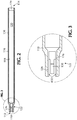
FIG. 2 shows a cross-sectional view of an elongate tube in accordance with one or more embodiments of the disclosure; -
FIG. 3 shows an expanded view of a portion of the elongate tube ofFIG. 2 ; -
FIG. 4 shows a cross-sectional view of an elongate tube in accordance with one or more embodiments of the disclosure; -
FIG. 5 shows an expanded view of a portion of the elongate tube ofFIG. 4 ; -
FIG. 6 shows an expanded view of a portion of the elongate tube ofFIG. 4 ; -
FIG. 7 shows a cross-sectional view of a plunger rod in accordance with one or more embodiments of the disclosure; -
FIG. 8 shows a cross-sectional view of a plunger rod in accordance with one or more embodiments of the disclosure; -
FIG. 9 shows an expanded view of a portion of the plunger rod ofFIG. 7 ; -
FIG. 10 shows an expanded view of a portion of the plunger rod ofFIG. 8 ; -
FIG. 11 shows a partial perspective view of a medicament insertion tool in accordance with one or more embodiments of the disclosure; -
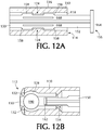
FIG 12A shows an expanded view of the distal end of a medicament insertion tool in the ready-to-use configuration in accordance with one or more embodiments of the disclosure; -
FIG. 12B shows an expanded view of the proximal end of a medicament insertion tool in the ready-to-use configuration in accordance with one or more embodiments of the disclosure; -
FIG. 13A shows an expanded view of the distal end of a medicament insertion tool after delivery, in accordance with one or more embodiments of the disclosure; and -
FIG. 13B shows an expanded view of the proximal end of a medicament insertion tool after delivery, in accordance with one or more embodiments of the disclosure. - Medicaments that can be delivered using an apparatus of the present disclosure can be in the forms of inserts (i.e., tablets or suppositories), capsules, creams, gels, etc. Drug substances that can be incorporated into the medicaments include those suitable for either human or veterinary therapy. The medicaments can be intended for oral administration when human or veterinary patients will not readily swallow a dosage form or can be intended for administration into a body cavity or onto the eye, where a drug will have a local effect or be absorbed through mucosa.
- For purposes of illustration, an applicator device particularly suited for administering a solid dosage form intravaginally will be described below. Those skilled in the art will be aware of modifications that can be made for administering medicaments of various other types into other body cavities. By selecting an appropriate body length, embodiments of the device described below can be used for intrauterine medicament administration.
- Referring to
FIG. 1 , one or more embodiments are directed to assemblies 100 for inserting a solid dosage form, such astablet 190, into a body cavity. The body cavity can be any suitable body cavity depending on the medication to be delivered. The body cavity can be one or more of a mouth, vagina, nostril, ear, or anus. Theassemblies 100 comprise anelongate tube 110, also referred to as a barrel, and aplunger rod 150. Some embodiments of theassembly 100 further comprise atablet 190. -
FIGS. 1 to 6 show embodiments ofelongate tubes 110 in accordance with one or more embodiments. Theelongate tube 110 has aproximal end 112, adistal end 114, anouter surface 116 and aninner surface 118. Anopening 120 extends from thedistal end 114 to theproximal end 112 and forms a cavity within theelongate tube 110. The cavity holds and guides theplunger rod 150 as it moves to expel the medicament. - The shape of the
elongate tube 110, in cross-section, can be any suitable shape including, but not limited to, circular, elliptical, square, triangular, pentagonal, hexagonal or octagonal. Theelongate tube 110 shown in the figures has a round cross-section so that the majority of the elongate tube appears to be cylindrical. The shape of the cavity can be the same or different from the outer shape. For example, the outer surface of theelongate tube 110 may have a hexagonal cross-section, while the cavity on the inner surface is circular. - The
proximal end 112 of theelongate tube 110 includes asupport section 122. Thesupport section 122 supports atablet 190, capsule, suppository or other suitable medication dosage form. Thesupport section 122 orproximal end 112 supports a medicament for delivery to a body cavity. Although the term "tablet" is sometimes used throughout this specification to describe the medicament, it will be understood by those skilled in the art that the dosage form is not limited to tablets. - The
support section 122 at theproximal end 112 of theelongate tube 110 includes at least two components to support the medicament. In the present invention, as shown inFIGS. 3-5 , thesupport section 122, orproximal end 112 of theelongate tube 110, includes at least twotongues 126 that can support the medicament. Thetongues 126 can be shaped to conform to the shape of the medicament so that there is greater surface area contact between the tongue and the medicament. For example, in some embodiments thetongues 126 compriseconcave walls 128 which engage a convex surface of the medicament. The at least twotongues 126 help prevent the medicament from being prematurely expelled from theproximal end 112 of theelongate tube 110. - In some embodiments, the
proximal end 112 of theelongate tube 110 further includes at least twolips 130. The at least twolips 130 help prevent lateral movement of the medicament. As a result, thelips 130 help hold the medicament in place until the user is ready to expel the medicament. The at least twolips 130 of some embodiments are biased inwardly from the outer surface of theelongate tube 110. Thelips 130 can also be shaped to conform to the medicament in similar fashion as thetongues 126. This may allow thelips 130 to be more effective at retaining the medicament so that there is a decreased potential for premature expulsion of the medicament. - The
elongate tube 110 can include at least onetooth 132 at thesupport section 122. The at least onetooth 132 can be seen inFIGS. 3 and5 and are positioned on thetongues 126. The at least onetooth 132 extends inwardly from thetongues 126 and can serve to prevent the medicament from being prematurely expelled by providing an additional barrier that must be overcome during expulsion. The number ofteeth 132 can vary depending on the specific shape and size of the medicament and thesupport section 122. In some embodiments, eachtongue 126 has at least onetooth 132. In one or more examples, eachtongue 126, as shown in the Figures, has at least twoteeth 132. - The specific medication in the tablet, capsule, etc., is dependent only on the desired treatment. In one or more examples, a tablet comprises an estrogen, such as estradiol, and, optionally, may also include any suitable binders, fillers and excipients. In some examples, a tablet comprises an estrogen in an amount up to about 50 mcg (micrograms). In one or more examples, a tablet comprises an estrogen in an amount in the range of about 5 mcg to about 40 mcg. In some examples, a tablet comprises an estrogen in an amount in the range of about 10 mcg to about 25 mcg.
- The
elongate tube 110 includes at least oneradial discontinuity 124 about theinner surface 118. In some examples, the at least oneradial discontinuity 124 is spaced a distance from thedistal end 114 of theelongate tube 110 as shown in the Figures. However, in the present invention, theradial discontinuity 124 is positioned immediately adjacent thedistal end 114. For example, theradial discontinuity 124 is positioned at a distance of up to about 50% of the overall length of theelongate tube 110 from thedistal end 114, so that the at least one radial discontinuity is positioned closer to thedistal end 114 than to theproximal end 112 of theelongate tube 110. For example, the at least one radial discontinuity is at least about 1,27 mm (0,05 inches) from the distal end, or in the range of 0,762 to 2,286 mm (0,03 to 0,09 inches) from the distal end. Without being bound by any particular theory of operation, it is believed that this placement of the radial discontinuity prevents or minimizes deformation and bowing of theplunger rod 150 during use. - As used in this specification and the appended claims, the term "discontinuity" means any intentional irregularity in the smoothness of the
inner surface 118 of theelongate tube 110. Theradial discontinuity 124 can be one or more of a projection and a recess. In the embodiment shown in the Figures, theradial discontinuity 124 is a projection extending inwardly from theinner surface 118 of theelongate tube 110. As will be discussed further below, the shape of the discontinuity is such that the discontinuity can cooperatively interact or engage with at least one projection on the plunger rod. In some embodiments, the discontinuity is a recess and the plunger rod includes at least one projection that cooperatively interacts or engages with the recess. - The example of
FIG. 1 includes a roughened area orcorrugations 134 on theouter surface 116 of theelongate tube 110. Thecorrugations 134 can be any suitable pattern or configuration and provide a textured area for a user to grip theassembly 100. Thecorrugations 134 of some examples help to prevent slippage of the elongate tube between the user's fingers. Thecorrugations 134 can be, for example, cross-hatched or bumps and be formed into any shape. For example, thecorrugations 134 can include a logo, product or company name embossed therein, or thecorrugations 134 can form a logo, product or company name. - The dimensions of the
elongate tube 110 can vary depending on the desired use of the insertion tool. In some example the elongate tube has a length in the range of about 10,16 cm to about 15,24 cm (4 inches to about 6 inches), or in the range of about 11,42 cm to about 13,9 cm (4,5 inches to about 5,5 inches) or in the range of about 12,19 cm to about 12,7 cm (4,8 inches to about 5 inches). In one or more examples, the elongate tube has a length of about 12,6124 cm (4, 906 inches) ± 1%. The diameter of the elongate tube can also vary depending on, for example, the medicament to be dispensed from the elongate tube. In some embodiments, the elongate tube has an outer diameter in the range of about 2,54 mm to about 20,32 mm (0,1 inches to about 0,8 inches), or in the range of about 5,08 mm to about 14,24 mm (0,2 inches to about 0,6 inches) or in the range of about 7,62 mm to about 10,16 mm (0,3 inches to about 0,4 inches). In one or more examples, the elongate tube has an outer diameter of about 7,9756 mm (0,314 inches) ± 0.5%. - Referring to
FIGS. 7 to 10 , theassembly 100 includes aplunger rod 150 which is used to expel the medicament from thesupport section 122. Theplunger rod 150 has anelongate body 152 with aproximal end 154 and adistal end 156 and can slidably engage theelongate tube 110 within the cavity. The plunger rod comprises at least two axial spaced projections adjacent thedistal end 156 of theelongate body 152. Theprojections 158 are sized and shaped to cooperatively engage the at least oneradial discontinuity 124 on theinner surface 118 of theelongate tube 110. - Including at least two
projections 158 can provide additional control over the positioning of theplunger rod 150 within theelongate tube 110 as described further below. - The
plunger rod 150 can be solid or hollow and has a cross-sectional shape that will allow it to slide within theelongate tube 110. For example, if the elongate tube has a round, triangular, or square cross-sectional shape, the plunger rod can have a similar shape. However, it is not always necessary for the shapes to be similar. - As shown in the Figures, the
elongate body 152 of theplunger rod 150 of an embodiment comprises at least two intersectingbeams 160. The intersecting beams 160 extend from thedistal end 156 to theproximal end 154 of theplunger rod 150. In one or more embodiments, there are two intersectingbeams 160 such thatelongate body 152 has a cruciform-shaped cross section comprising four rays. In some embodiments, theplunger rod 150 comprises three intersectingbeams 160, or more, such that there are six rays (or two times the number of beams). The number ofrays including projections 158 can vary depending on, for example, the size of the assembly, plunger rod and medicament to be delivered. In some embodiments, two of the four rays contain at least oneprojection 158. In one or more embodiments, two of four rays contain two axially spacedprojections 158 as illustrated in the Figures. - In some embodiments, the
proximal end 154 of theplunger rod 150 is undivided. This means that theproximal end 154 of theplunger rod 150 is a solid material and does not contain specific definable rays. In these embodiments, the intersecting beams 160 extend from thedistal end 156 toward theproximal end 154 of theplunger rod 150 and either taper or abruptly transition to the undivided portion. - The
proximal end 154 of theplunger rod 150 can have any shape suitable for contacting and expelling the medicament. In some embodiments, theproximal end 154 of theplunger rod 150 is blunt. This can be seen in the Figures as aproximal cap 162 on theproximal end 154 of theplunger rod 150. Theproximal cap 162 can be blunt (or flat ended) or have a shape conforming to the portion of the medicament that theproximal cap 162 will contact. In other embodiments, theproximal end 154 has a rounded surface. Various embodiments avoid providing any sharp edges that might come into contact with patient epithelial tissues. In certain embodiments, the length ofplunger rod 150 is such that the rod will remain substantially completely withinelongate body 152 after a medicament has been expelled, thereby avoiding contact between the plunger rod and epithelial tissues. - The pushing
region 166 of theplunger rod 150 can be the same size (e.g., radially) or a different size than the remainder of theplunger rod 150. For example, the pushingregion 166 of the plunger rod shown in the Figures is smaller than the remainder of theplunger rod 150. In some embodiments where the pushingregion 166 is smaller than the rest of the plunger rod, the pushing region and theproximal cap 162 are more easily able to fit into thesupport section 122 to expel the medicament. Thesupport section 122 may have components (e.g., fingers, tongues and teeth) which make thesupport section 122 smaller than the remainder of theelongate tube 110. Therefore, if the pushingregion 166 of theplunger rod 150 is smaller in diameter, then the pushingregion 166 will more easily fit into thesupport section 122. - The
distal end 156 of theplunger rod 150 may also include athumbpress 164 which can be smooth or textured. In some examples, thethumbpress 164 is textured to prevent slippage of the user's thumb or finger from thethumbpress 164. - The
plunger rod 150 also includes oneopening 168 adjacent each of the at least two axially spacedprojections 158. Theopening 168 can be positioned along the rays containing the projections adjacent the projections. Without being bound by any particular theory of operation, it is believed that the openings allow for some flexing in theplunger rod 150 at theprojections 158 so that the projections can move relative to the at least one discontinuity. - In the present invention, as shown in
FIG. 12A , the at least oneradial discontinuity 124 on theelongate tube 110 is cooperatively engaged between the at least two axially spacedprojections 158 on the elongate body of theplunger rod 150. Such an arrangement is suitable to substantially prevent spontaneous movement of theplunger rod 150 distally or proximally with respect to theelongate tube 110. As used in this specification and the appended claims, the term "substantially prevent spontaneous movement" means that the plunger rod does not move distally or proximally with respect to theelongate tube 110 to the extent that one or more of the projections moves past the at least one discontinuity or that the medicament is spontaneously expelled from the assembly. This means that minor movement of the plunger rod either distally or proximally with respect to the elongate tube is possible, but such movement is inconsequential to the operation of the assembly. - The physical dimensions of the
plunger rod 150 can vary depending on the desired use of the suppository insertion tool. The dimensions of the plunger rod allow the plunger rod to cooperatively interact with the elongate tube. In some embodiments, the plunger rod has a length in the range of about 10,16 cm to about 15,24 cm (4 inches to about 6 inches), or in the range of about 11,43 cm to about 13,97 cm (4,5 inches to about 5,5 inches), or in the range of about 12,192 cm to about 12,7 cm (4,8 inches to about 5 inches). In one or more embodiments, the plunger rod has a length of about 12,584 cm (4,960 inches) ± 1%. The diameter of the plunger rod can also vary depending on, for example, the medicament to be dispensed from the elongate tube. In some embodiments, the plunger rod has a diameter near the proximal end in the range of about 12,7 mm to about 15,24 mm (0,05 inches to about 0,6 inches), or in the range of about 2,54 mm to about 10,16 mm (0,1 inches to about 0,4 inches), or in the range of about 3,556 mm to about 3,81 mm (0,14 inches to about 0,15 inches). In one or more embodiments, the elongate tube has an outer diameter of about 3,5814 mm (0,141 inches) ± 1%. - The operation of one or more embodiments of the assembly is described with respect to
FIGS. 12 and13 . As shown inFIG. 12A , the at least two axially spacedprojections 158 on theelongate body 152 of theplunger rod 150 are positioned on opposite sides of the at least onediscontinuity 124 on theinner surface 118 of theelongate tube 110. Theplunger rod 150 can be placed into this position during manufacturing of the assembly (i.e., before sale of a completed unit) or after manufacture (i.e., by an end user). The position of theplunger rod 150 shown inFIG. 12A substantially prevents proximal or distal movement of the plunger rod. This position may be useful to ensure that the end user has the assembly in a ready-to-use configuration. - The at least one
projection 158 is shown positioned at a sufficient distance from thedistal end 156 of theplunger rod 150 such that theproximal end 154 of theplunger rod 150, and theproximal cap 162, are positioned distally from thetablet 190. Referring toFIG. 12B , theproximal end 154 of theplunger rod 150 is in position to expel thetablet 190 upon proximal movement of theplunger rod 150. However, because of the placement of theprojections 158 relative to the at least onediscontinuity 124, expulsion cannot occur spontaneously. In the positions shown inFIGS. 12A and 12B , the assembly is loaded with atablet 190 and ready for use. - Referring to
FIGS. 13A and 13B , proximal movement of theplunger rod 150 relative to theelongate tube 110 expels thetablet 190. InFIG. 13A , it can be seen that both of theprojections 158 on theplunger rod 150 have been moved proximal of the at least onediscontinuity 124. Since this cannot occur spontaneously, it will likely be the result of proximally directed force on theplunger rod 150. For example, the user may apply pressure to thethumbpress 164 to expel thetablet 190. InFIG. 13B , theproximal cap 162 of theplunger rod 150 has contacted thetablet 190 and forced it out of theelongate tube 110. If theproximal end 112 of theelongate tube 110 has been positioned in a body cavity, thetablet 190 will be expelled into that cavity. - The
projections 158 on theplunger rod 150 may be positioned a distance from thedistal end 156 of theplunger rod 150 and thethumbpress 164, so that proximal movement of theplunger rod 150 causes thethumbpress 164 to contact thedistal end 114 of theelongate tube 110. The contact of thethumbpress 164 with theelongate tube 110 may serve to stop further proximal movement so that the proximal cap of theplunger rod 150 does not protrude from the proximal end of theelongate tube 110. The distance between thethumbpress 164 and theprojections 158 can be tuned to allow or prevent such protrusion. - In alternate embodiments, there are two radial discontinuities124 on the
inner surface 118 of theelongate tube 110. Theradial discontinuities 124 are spaced along the length of theelongate tube 110 so that there is a distal discontinuity and a proximal discontinuity. Theplunger rod 150 includes asingle projection 158 which can be moved from the distal discontinuity to the proximal discontinuity. In the ready-to-use position, theprojection 158 is engaged with the distal discontinuity which holds the plunger rod in position to expel the medicament. When force is applied to the thumbpress in the proximal direction, theprojection 158 slides from the distal discontinuity to the proximal discontinuity, and the proximal end of the plunger rod expels the medicament. - Both the
elongate tube 110 and theplunger rod 150 can be made from any suitable materials. Additionally, each component can be integrally formed or made up of multiple pieces. In some embodiments, each of the elongate tube and the plunger rod are independently made from a material comprising one or more of polypropylene and high-density polyethylene. The apparatus is well-suited for inexpensive component manufacturing from any desired thermoplastic materials, using single- or multiple-cavity molds. In embodiments, the apparatus is intended for delivering a prefilled medicament and will be discarded after use. - Embodiments of the disclosed apparatus can reproducibly expel a 6 mm diameter tablet to distances at least 25,4 cm (10 inches) from the proximal tip.
- Certain modifications can be made to the apparatus for delivering fluid medicaments, such as semi-solid creams, gels, etc., and liquids. For such medicaments, the proximal end of the elongate tube will not have the above-described support section for retaining a solid dosage form but rather will have a substantially uniform internal shape and be capable of being closed, such as with a removable plug, to contain and protect the contained medicament until it is intended to be dispensed. The plunger tip also will have a sealing relationship with the interior surface of the elongate tube. For example, the proximal end can be fitted with a tip that enables delivery of a medicament in desired dimensions, and facilitates application onto a desired portion of the anatomy. The tip can be affixed after removal of the closure, or can be permanently or removably attached during manufacture of the elongate tube or after filling of the medicament into the tube. For fluid medicaments, the contained medicament quantity can be delivered in a single step or can be delivered in portions, at different times and/or to different locations.
- Applicator devices, constructed in accordance with this disclosure, are tested for their ability to reproducibly expel a 6 mm diameter cylindrical tablet. Applicators supplied with the commercial product VAGIFEM® estradiol (10 mcg) vaginal tablets, and having similar barrel and plunger rod dimensions, are also tested. In the tests, a unit is unwrapped and the presence of a tablet contained at the proximal end of the applicator is verified. The applicator is placed flat on a hard surface and gripped with the hand, such that a finger placed over the distal plunger end can depress the plunger. Pressure is gradually applied to the plunger end until the device is actuated and the tablet is expelled. The tablet distance from the applicator proximal tip is then measured. The table below shows results obtained from testing units from two manufacturing batches of the "test" applicators according to the present disclosure and four lot numbers of marketed VAGIFEM applicators. The VAGIFEM applicators appear to be constructed generally in accordance with the description in
U.S. Patent No. 5,860,946 .Unit Distance Traveled (inches) Test VAGIFEM® K11K00542A K11K00543A AE70133 AE70253 AE70273 AE70274 1 15 17 6 15 3 42 2 29 19 7 22 4 16 3 29 16 9 54 4 38 4 26 27 8 42 3 40 5 25 23 7 21 4 46 6 30 20 12 70 5 18 7 26 29 7 34 6 36 8 25 24 4 12 7 18 9 30 26 5 33 5 34 10 38 30 3 60 3 43 11 21 31 4 10 4 33 12 28 23 7 27 5 10 Average 26.83 23.75 6.58 33.33 4.42 31.17 Std. Dev. 5.54 5.03 2.47 19.57 1.24 12.29
Claims (13)
- An assembly (100) for introducing a medicament into a body cavity, the assembly comprising:an elongate tube (110) having a proximal end (112), a distal end (114), an outer surface (116), an inner surface (118) and an opening (120) extending from the distal end (114) to the proximal end (112), the proximal end adapted to support a medicament, the elongate tube (110) comprising at least one radial discontinuity (124) adjacent the distal end (114) and extending inwardly from the inner surface (118) of the tube (110); anda plunger rod (150) having an elongate body (152) with a distal end (156) and a proximal end (154), the plunger rod adapted to be slidably engaged within the tube (110), the plunger rod comprising at least two axially spaced projections (158) adjacent the distal end (156) of the elongate body (152) that cooperatively engages with the at least one radial discontinuity (124), the plunger rod (150) including an opening (168) adjacent each of the at least two axially spaced projections (158) to allow flexion of the plunger rod adjacent each of the at least two axially spaced projections;wherein the at least one radial discontinuity (124) on the elongate tube (110) cooperatively engages between the at least two axially spaced projections (158) on the elongate body (152) of the plunger rod (150), such that spontaneous movement of the plunger rod distally or proximally with respect to the elongate tube (110) is substantially prevented,wherein the proximal end (112) of the elongate tube (110) comprises at least two tongues (126) adapted to support a medicament (190).
- The assembly of claim 1, wherein the opening (168) is a cutout that extends below each of the at least two axially spaced projections (158).
- The assembly of claim 1, wherein the proximal end (112) of the elongate tube (110) contains a medicament (190).
- The assembly of claim 3, wherein the medicament (190) is a tablet.
- The assembly of claim 3, wherein the at least two axially spaced projections (158) on the elongate body are positioned a sufficient distance from the distal end (156) of the plunger rod (150) such that when the at least one radial discontinuity (124) on the elongate tube is cooperatively engaged between the at least two axially spaced projections, proximal movement of the plunger rod with respect to the elongate tube (110) causes the proximal end (154) of the plunger rod to expel the medicament from the proximal end (112) of the elongate tube.
- The assembly of claim 1, wherein the elongate body (152) of the plunger rod comprises two intersecting beams (160) extending from the distal end (156) to the proximal end (154), such that elongate body has a cruciform-shaped cross section comprising four rays.
- The assembly of claim 6, wherein two of the four rays each contain two axially spaced projections (158).
- The assembly of claim 1, wherein the distal end (156) of the plunger rod (150) is undivided.
- The assembly of claim 1, wherein the distal end (156) of the plunger rod (150) is blunt or rounded.
- The assembly of claim 1, wherein the at least two tongues (126) each comprise recessed walls (128) adapted to engage the surface of the medicament.
- The assembly of claim 1, wherein the at least two tongues (126) prevent the medicament from being prematurely expelled from the proximal end (112) of the elongate tube (110).
- The assembly of claim 1, wherein the proximal end (112) of the elongate tube (110) further comprises at least two lips (130) adapted to prevent lateral movement of the medicament.
- The assembly of claim 12, wherein the at least two lips (130) are biased inward from the outer surface of the elongate tube at its proximal end.
Applications Claiming Priority (2)
| Application Number | Priority Date | Filing Date | Title |
|---|---|---|---|
| US13/921,429 US9517328B2 (en) | 2013-06-19 | 2013-06-19 | Medicament applicator |
| PCT/US2014/042318 WO2014204805A1 (en) | 2013-06-19 | 2014-06-13 | Medicament applicator |
Publications (2)
| Publication Number | Publication Date |
|---|---|
| EP3010575A1 EP3010575A1 (en) | 2016-04-27 |
| EP3010575B1 true EP3010575B1 (en) | 2021-07-21 |
Family
ID=51136833
Family Applications (1)
| Application Number | Title | Priority Date | Filing Date |
|---|---|---|---|
| EP14736562.1A Active EP3010575B1 (en) | 2013-06-19 | 2014-06-13 | Medicament applicator |
Country Status (4)
| Country | Link |
|---|---|
| US (3) | US9517328B2 (en) |
| EP (1) | EP3010575B1 (en) |
| ES (1) | ES2892287T3 (en) |
| WO (1) | WO2014204805A1 (en) |
Families Citing this family (15)
| Publication number | Priority date | Publication date | Assignee | Title |
|---|---|---|---|---|
| US20100076370A1 (en) | 2008-09-23 | 2010-03-25 | Infusion Advancements, LLC. | Apparatus and methods for purging catheter systems |
| US9517328B2 (en) * | 2013-06-19 | 2016-12-13 | Kashiv Pharma, Llc | Medicament applicator |
| PT3682915T (en) * | 2015-10-30 | 2023-06-26 | Acelrx Pharmaceuticals Inc | Apparatus and methods for dispensing oral transmucosal dosage forms |
| US10076650B2 (en) | 2015-11-23 | 2018-09-18 | Warsaw Orthopedic, Inc. | Enhanced stylet for drug depot injector |
| USD802755S1 (en) | 2016-06-23 | 2017-11-14 | Warsaw Orthopedic, Inc. | Drug pellet cartridge |
| US10434261B2 (en) | 2016-11-08 | 2019-10-08 | Warsaw Orthopedic, Inc. | Drug pellet delivery system and method |
| JP1594716S (en) * | 2017-03-07 | 2018-01-15 | ||
| BR102017016174B1 (en) * | 2017-07-27 | 2020-08-11 | Doris Maria Hexsel | WRAPPING DEVICE FOR DISPENSING TOPICAL PRODUCTS FOR ORAL, VULVAR AND ANAL USE, COUPLABLE TO PORTABLE APPLICATOR FOR VAGINAL AND RECTAL USES |
| US20210128840A1 (en) * | 2018-04-09 | 2021-05-06 | Sio2 Medical Products, Inc. | Stretchable plunger assemblies |
| WO2020092241A1 (en) * | 2018-10-28 | 2020-05-07 | Cardiac Pacemakers, Inc. | Implantable monitor introducer design features |
| CN109224274B (en) * | 2018-11-28 | 2021-04-27 | 江西仁和药用塑胶制品有限公司 | Unilateral capsule pusher of vagina or anus |
| CN109260580B (en) * | 2018-11-28 | 2021-03-23 | 窦玉芝 | Two-side capsule pushing device for vagina or anus |
| CN109621061A (en) * | 2018-12-31 | 2019-04-16 | 孙孝国 | A kind of department of general surgery's wound-cleaning device |
| KR102483864B1 (en) * | 2020-05-13 | 2023-01-03 | 주식회사 웨트러스트 | Functional Drug injection module including a cover unit for lubrication coating |
| IT202100023285A1 (en) * | 2021-09-09 | 2023-03-09 | Irccs Azienda Ospedaliero Univ Di Bologna | DEVICE FOR THE POSITIONING OF ORGANIC TISSUE AND RELATED APPARATUS |
Citations (3)
| Publication number | Priority date | Publication date | Assignee | Title |
|---|---|---|---|---|
| JPS60138543U (en) * | 1984-02-28 | 1985-09-13 | 三菱鉛筆株式会社 | syringe |
| EP0611035A1 (en) * | 1993-01-12 | 1994-08-17 | Owen Mumford Limited | Improvement relating to devices for generating intermittent motion |
| WO2012050511A1 (en) * | 2010-10-11 | 2012-04-19 | Shl Group Ab | Medicament delivery device |
Family Cites Families (41)
| Publication number | Priority date | Publication date | Assignee | Title |
|---|---|---|---|---|
| US2754822A (en) * | 1954-02-15 | 1956-07-17 | Emelock Melvin | Instrument for the administration of suppositories |
| US3635218A (en) * | 1970-03-23 | 1972-01-18 | Eiliot Lab Inc | Combination bulb-piston syringe |
| US3766921A (en) * | 1971-08-18 | 1973-10-23 | Procter & Gamble | Proximal apex tampon |
| US3780735A (en) * | 1972-02-03 | 1973-12-25 | J Crouter | Dose syringe |
| US4361150A (en) | 1980-04-07 | 1982-11-30 | Voss Joseph A | Extruded plastic hygienic applicator |
| US4421504A (en) * | 1981-09-08 | 1983-12-20 | Kline Larry H | Lubricating object injector utilizing a single plunger |
| US4341211A (en) | 1981-09-08 | 1982-07-27 | Kline Larry H | Lubricating object applicator |
| US4496341A (en) | 1982-04-12 | 1985-01-29 | Brucks Anton B | Apparatus for vaginal medication application |
| EP0114811A1 (en) | 1982-07-23 | 1984-08-08 | KLINE, Larry Harold | Lubricating object applicator |
| DE8409756U1 (en) | 1984-03-30 | 1984-08-16 | Novo Industri A/S, Bagsvaerd | DISPOSABLE DEVICE FOR INSERTING A SUPPOSITORIUM |
| US4826483A (en) * | 1988-05-05 | 1989-05-02 | Paul F. Boyd | Non-reusable syringe |
| FR2634650B1 (en) * | 1988-08-01 | 1990-11-02 | Labouze Joseph | NON REUSABLE SYRINGE |
| US4911687A (en) * | 1988-08-22 | 1990-03-27 | Playtex Family Products, Inc. | Compact tampon applicator with snap-action hinged panels |
| US5084017A (en) * | 1989-10-10 | 1992-01-28 | John Maffetone | Self disabling, single use, hypodermic syringe |
| US4990136A (en) | 1989-10-12 | 1991-02-05 | Warner-Lambert Company | Suppository applicator |
| US5213566A (en) | 1991-07-02 | 1993-05-25 | Ortho Pharmaceutical Corporation | Prefilled suppository applicator |
| US5330427A (en) | 1991-07-02 | 1994-07-19 | Ortho Pharmaceutical Corporation | Prefilled suppository applicator |
| AR243387A1 (en) * | 1991-10-03 | 1993-08-31 | Cesar Gabriel Corsich | Hypodermic syringe with a locking stopper, which prevents it from being reloaded and reused. |
| US5263934A (en) * | 1991-11-28 | 1993-11-23 | Haak Abraham Van Den | Stroke limiting syringe with retractable needle |
| US5352208A (en) * | 1992-11-30 | 1994-10-04 | Robinson Wilbur D | Safe non-reusable hypodermic syringe |
| US5380295A (en) * | 1992-12-14 | 1995-01-10 | Mallinckrodt Medical, Inc. | Delivery apparatus with mechanism preventing rearward movement of a piston disposed therein |
| US5395308A (en) | 1993-09-24 | 1995-03-07 | Kimberly-Clark Corporation | Thermoplastic applicator exhibiting accelerated breakup when immersed in water |
| US5788664A (en) | 1994-11-30 | 1998-08-04 | Scalise; Gaspare | Suppository applicator |
| US5697918A (en) * | 1995-02-23 | 1997-12-16 | Ultradent Products, Inc. | Systems for storing and dispensing dental compositions |
| ATE240764T1 (en) | 1996-07-05 | 2003-06-15 | Novo Nordisk As | DEVICE FOR INSERTING A SUPPOSITORY |
| GB2369063B (en) | 1999-04-29 | 2003-07-16 | Peter James Brian Lamb | Device for depositing a non-flowable object or a non-flowable medicament in a body cavity |
| MXPA04005445A (en) * | 2001-12-05 | 2005-03-23 | Barr Lab Inc | Oral contraceptives to prevent pregnancy and diminish premenstrual symptomatology. |
| GB2385274B (en) | 2002-02-13 | 2004-04-14 | Ming-Jeng Shue | Vaginal suppository delivery device |
| US7104968B2 (en) | 2002-06-14 | 2006-09-12 | Mcneil-Ppc, Inc. | Applicator device for suppositories and the like |
| US7217252B2 (en) | 2002-06-14 | 2007-05-15 | Mcneil-Ppc, Inc. | Applicator device for medicated materials |
| CA2513007C (en) | 2003-01-16 | 2009-11-03 | Femmepharma Holding Company, Inc. | Vaginal or rectal applicator |
| US7118550B2 (en) * | 2003-07-10 | 2006-10-10 | B. Braun Medical | Side-delivery suppository dispenser |
| US8057433B2 (en) | 2004-07-08 | 2011-11-15 | Drugtech Corporation | Delivery system |
| WO2006121754A2 (en) | 2005-05-05 | 2006-11-16 | Robert H. Carpenter Dvm, Pc | Device capable of delivery of highly soluble pharmaceutical dose forms into body spaces |
| JP4332532B2 (en) | 2006-02-16 | 2009-09-16 | 明敏 黄 | Drug administration device |
| US20070225655A1 (en) | 2006-03-22 | 2007-09-27 | Sjoerd Osinga | Intravaginal medicament applicators |
| US8308675B2 (en) | 2006-03-31 | 2012-11-13 | Mcneil-Ppc, Inc. | Applicator device |
| KR20090038907A (en) * | 2006-07-17 | 2009-04-21 | 유로-셀띠끄 소시에떼 아노님 | Dosing tool |
| US7666160B2 (en) | 2006-12-29 | 2010-02-23 | Kimberly-Clark Worldwide, Inc. | Delivery device |
| JP5841051B2 (en) | 2009-07-10 | 2016-01-06 | ベクトン・ディキンソン・アンド・カンパニーBecton, Dickinson And Company | Cleaning syringe assembly with controlled pulsatile cleaning function |
| US9517328B2 (en) * | 2013-06-19 | 2016-12-13 | Kashiv Pharma, Llc | Medicament applicator |
-
2013
- 2013-06-19 US US13/921,429 patent/US9517328B2/en active Active
-
2014
- 2014-06-13 EP EP14736562.1A patent/EP3010575B1/en active Active
- 2014-06-13 WO PCT/US2014/042318 patent/WO2014204805A1/en not_active Ceased
- 2014-06-13 ES ES14736562T patent/ES2892287T3/en active Active
-
2016
- 2016-11-07 US US15/344,803 patent/US9884173B2/en active Active
-
2018
- 2018-02-05 US US15/888,330 patent/US10940300B2/en active Active
Patent Citations (3)
| Publication number | Priority date | Publication date | Assignee | Title |
|---|---|---|---|---|
| JPS60138543U (en) * | 1984-02-28 | 1985-09-13 | 三菱鉛筆株式会社 | syringe |
| EP0611035A1 (en) * | 1993-01-12 | 1994-08-17 | Owen Mumford Limited | Improvement relating to devices for generating intermittent motion |
| WO2012050511A1 (en) * | 2010-10-11 | 2012-04-19 | Shl Group Ab | Medicament delivery device |
Also Published As
| Publication number | Publication date |
|---|---|
| US20140378948A1 (en) | 2014-12-25 |
| US20180154125A1 (en) | 2018-06-07 |
| US20170050007A1 (en) | 2017-02-23 |
| US9517328B2 (en) | 2016-12-13 |
| ES2892287T3 (en) | 2022-02-03 |
| US10940300B2 (en) | 2021-03-09 |
| US9884173B2 (en) | 2018-02-06 |
| WO2014204805A1 (en) | 2014-12-24 |
| EP3010575A1 (en) | 2016-04-27 |
Similar Documents
| Publication | Publication Date | Title |
|---|---|---|
| US10940300B2 (en) | Medicament applicator | |
| JPH0517068Y2 (en) | ||
| EP0600864B1 (en) | Device for applying a drain | |
| JP4319357B2 (en) | Medication applicator | |
| US7666160B2 (en) | Delivery device | |
| US20100010471A1 (en) | Medication applicator device | |
| EP2167176B1 (en) | Syringe assembly including reuse prevention mechanism | |
| JPH0588628B2 (en) | ||
| NZ579803A (en) | Pre-filled applicator device for delivering medicine to a body cavity | |
| KR20080112240A (en) | Intravaginal drug topical device | |
| US10525242B2 (en) | Method and apparatus for inserting a rectal suppository | |
| US11439803B2 (en) | Medicant applicator | |
| US20180229016A1 (en) | Vaginal applicator for pharmaceutical preparations | |
| MXPA06001075A (en) | Syringe assembly having disabling mechanism. | |
| WO2006121754A2 (en) | Device capable of delivery of highly soluble pharmaceutical dose forms into body spaces | |
| US20150005700A1 (en) | Sanitary device for applying an active principle within a body cavity | |
| WO2019018913A1 (en) | Encasing device for dispensing topical products for oral, vulvar and anal use, which can be attached to a portable applicator for vaginal and rectal use | |
| CN204502074U (en) | Disposable vaginal administrator | |
| KR20190000726U (en) | indicator | |
| JPS6335263A (en) | Preparation administration device |
Legal Events
| Date | Code | Title | Description |
|---|---|---|---|
| PUAI | Public reference made under article 153(3) epc to a published international application that has entered the european phase |
Free format text: ORIGINAL CODE: 0009012 |
|
| 17P | Request for examination filed |
Effective date: 20151221 |
|
| AK | Designated contracting states |
Kind code of ref document: A1 Designated state(s): AL AT BE BG CH CY CZ DE DK EE ES FI FR GB GR HR HU IE IS IT LI LT LU LV MC MK MT NL NO PL PT RO RS SE SI SK SM TR |
|
| AX | Request for extension of the european patent |
Extension state: BA ME |
|
| DAX | Request for extension of the european patent (deleted) | ||
| STAA | Information on the status of an ep patent application or granted ep patent |
Free format text: STATUS: EXAMINATION IS IN PROGRESS |
|
| 17Q | First examination report despatched |
Effective date: 20190121 |
|
| GRAP | Despatch of communication of intention to grant a patent |
Free format text: ORIGINAL CODE: EPIDOSNIGR1 |
|
| STAA | Information on the status of an ep patent application or granted ep patent |
Free format text: STATUS: GRANT OF PATENT IS INTENDED |
|
| RIC1 | Information provided on ipc code assigned before grant |
Ipc: A61M 31/00 20060101AFI20210118BHEP |
|
| INTG | Intention to grant announced |
Effective date: 20210217 |
|
| GRAS | Grant fee paid |
Free format text: ORIGINAL CODE: EPIDOSNIGR3 |
|
| GRAA | (expected) grant |
Free format text: ORIGINAL CODE: 0009210 |
|
| STAA | Information on the status of an ep patent application or granted ep patent |
Free format text: STATUS: THE PATENT HAS BEEN GRANTED |
|
| AK | Designated contracting states |
Kind code of ref document: B1 Designated state(s): AL AT BE BG CH CY CZ DE DK EE ES FI FR GB GR HR HU IE IS IT LI LT LU LV MC MK MT NL NO PL PT RO RS SE SI SK SM TR |
|
| REG | Reference to a national code |
Ref country code: GB Ref legal event code: FG4D |
|
| REG | Reference to a national code |
Ref country code: CH Ref legal event code: EP |
|
| REG | Reference to a national code |
Ref country code: DE Ref legal event code: R096 Ref document number: 602014078886 Country of ref document: DE |
|
| REG | Reference to a national code |
Ref country code: AT Ref legal event code: REF Ref document number: 1412023 Country of ref document: AT Kind code of ref document: T Effective date: 20210815 |
|
| REG | Reference to a national code |
Ref country code: IE Ref legal event code: FG4D |
|
| REG | Reference to a national code |
Ref country code: LT Ref legal event code: MG9D |
|
| REG | Reference to a national code |
Ref country code: NL Ref legal event code: MP Effective date: 20210721 |
|
| REG | Reference to a national code |
Ref country code: AT Ref legal event code: MK05 Ref document number: 1412023 Country of ref document: AT Kind code of ref document: T Effective date: 20210721 |
|
| PG25 | Lapsed in a contracting state [announced via postgrant information from national office to epo] |
Ref country code: HR Free format text: LAPSE BECAUSE OF FAILURE TO SUBMIT A TRANSLATION OF THE DESCRIPTION OR TO PAY THE FEE WITHIN THE PRESCRIBED TIME-LIMIT Effective date: 20210721 Ref country code: SE Free format text: LAPSE BECAUSE OF FAILURE TO SUBMIT A TRANSLATION OF THE DESCRIPTION OR TO PAY THE FEE WITHIN THE PRESCRIBED TIME-LIMIT Effective date: 20210721 Ref country code: RS Free format text: LAPSE BECAUSE OF FAILURE TO SUBMIT A TRANSLATION OF THE DESCRIPTION OR TO PAY THE FEE WITHIN THE PRESCRIBED TIME-LIMIT Effective date: 20210721 Ref country code: FI Free format text: LAPSE BECAUSE OF FAILURE TO SUBMIT A TRANSLATION OF THE DESCRIPTION OR TO PAY THE FEE WITHIN THE PRESCRIBED TIME-LIMIT Effective date: 20210721 Ref country code: NL Free format text: LAPSE BECAUSE OF FAILURE TO SUBMIT A TRANSLATION OF THE DESCRIPTION OR TO PAY THE FEE WITHIN THE PRESCRIBED TIME-LIMIT Effective date: 20210721 Ref country code: PT Free format text: LAPSE BECAUSE OF FAILURE TO SUBMIT A TRANSLATION OF THE DESCRIPTION OR TO PAY THE FEE WITHIN THE PRESCRIBED TIME-LIMIT Effective date: 20211122 Ref country code: NO Free format text: LAPSE BECAUSE OF FAILURE TO SUBMIT A TRANSLATION OF THE DESCRIPTION OR TO PAY THE FEE WITHIN THE PRESCRIBED TIME-LIMIT Effective date: 20211021 Ref country code: BG Free format text: LAPSE BECAUSE OF FAILURE TO SUBMIT A TRANSLATION OF THE DESCRIPTION OR TO PAY THE FEE WITHIN THE PRESCRIBED TIME-LIMIT Effective date: 20211021 Ref country code: AT Free format text: LAPSE BECAUSE OF FAILURE TO SUBMIT A TRANSLATION OF THE DESCRIPTION OR TO PAY THE FEE WITHIN THE PRESCRIBED TIME-LIMIT Effective date: 20210721 Ref country code: LT Free format text: LAPSE BECAUSE OF FAILURE TO SUBMIT A TRANSLATION OF THE DESCRIPTION OR TO PAY THE FEE WITHIN THE PRESCRIBED TIME-LIMIT Effective date: 20210721 |
|
| REG | Reference to a national code |
Ref country code: ES Ref legal event code: FG2A Ref document number: 2892287 Country of ref document: ES Kind code of ref document: T3 Effective date: 20220203 |
|
| PG25 | Lapsed in a contracting state [announced via postgrant information from national office to epo] |
Ref country code: PL Free format text: LAPSE BECAUSE OF FAILURE TO SUBMIT A TRANSLATION OF THE DESCRIPTION OR TO PAY THE FEE WITHIN THE PRESCRIBED TIME-LIMIT Effective date: 20210721 Ref country code: LV Free format text: LAPSE BECAUSE OF FAILURE TO SUBMIT A TRANSLATION OF THE DESCRIPTION OR TO PAY THE FEE WITHIN THE PRESCRIBED TIME-LIMIT Effective date: 20210721 Ref country code: GR Free format text: LAPSE BECAUSE OF FAILURE TO SUBMIT A TRANSLATION OF THE DESCRIPTION OR TO PAY THE FEE WITHIN THE PRESCRIBED TIME-LIMIT Effective date: 20211022 |
|
| REG | Reference to a national code |
Ref country code: DE Ref legal event code: R097 Ref document number: 602014078886 Country of ref document: DE |
|
| PG25 | Lapsed in a contracting state [announced via postgrant information from national office to epo] |
Ref country code: DK Free format text: LAPSE BECAUSE OF FAILURE TO SUBMIT A TRANSLATION OF THE DESCRIPTION OR TO PAY THE FEE WITHIN THE PRESCRIBED TIME-LIMIT Effective date: 20210721 |
|
| PLBE | No opposition filed within time limit |
Free format text: ORIGINAL CODE: 0009261 |
|
| STAA | Information on the status of an ep patent application or granted ep patent |
Free format text: STATUS: NO OPPOSITION FILED WITHIN TIME LIMIT |
|
| PG25 | Lapsed in a contracting state [announced via postgrant information from national office to epo] |
Ref country code: SM Free format text: LAPSE BECAUSE OF FAILURE TO SUBMIT A TRANSLATION OF THE DESCRIPTION OR TO PAY THE FEE WITHIN THE PRESCRIBED TIME-LIMIT Effective date: 20210721 Ref country code: SK Free format text: LAPSE BECAUSE OF FAILURE TO SUBMIT A TRANSLATION OF THE DESCRIPTION OR TO PAY THE FEE WITHIN THE PRESCRIBED TIME-LIMIT Effective date: 20210721 Ref country code: RO Free format text: LAPSE BECAUSE OF FAILURE TO SUBMIT A TRANSLATION OF THE DESCRIPTION OR TO PAY THE FEE WITHIN THE PRESCRIBED TIME-LIMIT Effective date: 20210721 Ref country code: EE Free format text: LAPSE BECAUSE OF FAILURE TO SUBMIT A TRANSLATION OF THE DESCRIPTION OR TO PAY THE FEE WITHIN THE PRESCRIBED TIME-LIMIT Effective date: 20210721 Ref country code: CZ Free format text: LAPSE BECAUSE OF FAILURE TO SUBMIT A TRANSLATION OF THE DESCRIPTION OR TO PAY THE FEE WITHIN THE PRESCRIBED TIME-LIMIT Effective date: 20210721 Ref country code: AL Free format text: LAPSE BECAUSE OF FAILURE TO SUBMIT A TRANSLATION OF THE DESCRIPTION OR TO PAY THE FEE WITHIN THE PRESCRIBED TIME-LIMIT Effective date: 20210721 |
|
| 26N | No opposition filed |
Effective date: 20220422 |
|
| PG25 | Lapsed in a contracting state [announced via postgrant information from national office to epo] |
Ref country code: MC Free format text: LAPSE BECAUSE OF FAILURE TO SUBMIT A TRANSLATION OF THE DESCRIPTION OR TO PAY THE FEE WITHIN THE PRESCRIBED TIME-LIMIT Effective date: 20210721 |
|
| REG | Reference to a national code |
Ref country code: CH Ref legal event code: PL |
|
| REG | Reference to a national code |
Ref country code: BE Ref legal event code: MM Effective date: 20220630 |
|
| PG25 | Lapsed in a contracting state [announced via postgrant information from national office to epo] |
Ref country code: LU Free format text: LAPSE BECAUSE OF NON-PAYMENT OF DUE FEES Effective date: 20220613 Ref country code: LI Free format text: LAPSE BECAUSE OF NON-PAYMENT OF DUE FEES Effective date: 20220630 Ref country code: IE Free format text: LAPSE BECAUSE OF NON-PAYMENT OF DUE FEES Effective date: 20220613 Ref country code: CH Free format text: LAPSE BECAUSE OF NON-PAYMENT OF DUE FEES Effective date: 20220630 |
|
| PG25 | Lapsed in a contracting state [announced via postgrant information from national office to epo] |
Ref country code: BE Free format text: LAPSE BECAUSE OF NON-PAYMENT OF DUE FEES Effective date: 20220630 |
|
| PG25 | Lapsed in a contracting state [announced via postgrant information from national office to epo] |
Ref country code: HU Free format text: LAPSE BECAUSE OF FAILURE TO SUBMIT A TRANSLATION OF THE DESCRIPTION OR TO PAY THE FEE WITHIN THE PRESCRIBED TIME-LIMIT; INVALID AB INITIO Effective date: 20140613 |
|
| PG25 | Lapsed in a contracting state [announced via postgrant information from national office to epo] |
Ref country code: MK Free format text: LAPSE BECAUSE OF FAILURE TO SUBMIT A TRANSLATION OF THE DESCRIPTION OR TO PAY THE FEE WITHIN THE PRESCRIBED TIME-LIMIT Effective date: 20210721 Ref country code: CY Free format text: LAPSE BECAUSE OF FAILURE TO SUBMIT A TRANSLATION OF THE DESCRIPTION OR TO PAY THE FEE WITHIN THE PRESCRIBED TIME-LIMIT Effective date: 20210721 |
|
| PG25 | Lapsed in a contracting state [announced via postgrant information from national office to epo] |
Ref country code: MT Free format text: LAPSE BECAUSE OF FAILURE TO SUBMIT A TRANSLATION OF THE DESCRIPTION OR TO PAY THE FEE WITHIN THE PRESCRIBED TIME-LIMIT Effective date: 20210721 |
|
| PGFP | Annual fee paid to national office [announced via postgrant information from national office to epo] |
Ref country code: DE Payment date: 20250627 Year of fee payment: 12 |
|
| PGFP | Annual fee paid to national office [announced via postgrant information from national office to epo] |
Ref country code: GB Payment date: 20250627 Year of fee payment: 12 |
|
| PGFP | Annual fee paid to national office [announced via postgrant information from national office to epo] |
Ref country code: FR Payment date: 20250625 Year of fee payment: 12 |
|
| PGFP | Annual fee paid to national office [announced via postgrant information from national office to epo] |
Ref country code: ES Payment date: 20250701 Year of fee payment: 12 |
|
| PGFP | Annual fee paid to national office [announced via postgrant information from national office to epo] |
Ref country code: IT Payment date: 20250619 Year of fee payment: 12 |
|
| PG25 | Lapsed in a contracting state [announced via postgrant information from national office to epo] |
Ref country code: TR Free format text: LAPSE BECAUSE OF FAILURE TO SUBMIT A TRANSLATION OF THE DESCRIPTION OR TO PAY THE FEE WITHIN THE PRESCRIBED TIME-LIMIT Effective date: 20210721 |