EP3010397B2 - Respiratory therapy apparatus and methods - Google Patents
Respiratory therapy apparatus and methods Download PDFInfo
- Publication number
- EP3010397B2 EP3010397B2 EP14727016.9A EP14727016A EP3010397B2 EP 3010397 B2 EP3010397 B2 EP 3010397B2 EP 14727016 A EP14727016 A EP 14727016A EP 3010397 B2 EP3010397 B2 EP 3010397B2
- Authority
- EP
- European Patent Office
- Prior art keywords
- respiratory therapy
- sensor
- therapy apparatus
- breathing
- output
- Prior art date
- Legal status (The legal status is an assumption and is not a legal conclusion. Google has not performed a legal analysis and makes no representation as to the accuracy of the status listed.)
- Active
Links
Images


Classifications
-
- A—HUMAN NECESSITIES
- A61—MEDICAL OR VETERINARY SCIENCE; HYGIENE
- A61M—DEVICES FOR INTRODUCING MEDIA INTO, OR ONTO, THE BODY; DEVICES FOR TRANSDUCING BODY MEDIA OR FOR TAKING MEDIA FROM THE BODY; DEVICES FOR PRODUCING OR ENDING SLEEP OR STUPOR
- A61M16/00—Devices for influencing the respiratory system of patients by gas treatment, e.g. ventilators; Tracheal tubes
- A61M16/0003—Accessories therefor, e.g. sensors, vibrators, negative pressure
- A61M16/0006—Accessories therefor, e.g. sensors, vibrators, negative pressure with means for creating vibrations in patients' airways
-
- A—HUMAN NECESSITIES
- A61—MEDICAL OR VETERINARY SCIENCE; HYGIENE
- A61M—DEVICES FOR INTRODUCING MEDIA INTO, OR ONTO, THE BODY; DEVICES FOR TRANSDUCING BODY MEDIA OR FOR TAKING MEDIA FROM THE BODY; DEVICES FOR PRODUCING OR ENDING SLEEP OR STUPOR
- A61M16/00—Devices for influencing the respiratory system of patients by gas treatment, e.g. ventilators; Tracheal tubes
- A61M16/20—Valves specially adapted to medical respiratory devices
-
- A—HUMAN NECESSITIES
- A63—SPORTS; GAMES; AMUSEMENTS
- A63B—APPARATUS FOR PHYSICAL TRAINING, GYMNASTICS, SWIMMING, CLIMBING, OR FENCING; BALL GAMES; TRAINING EQUIPMENT
- A63B21/00—Exercising apparatus for developing or strengthening the muscles or joints of the body by working against a counterforce, with or without measuring devices
- A63B21/00192—Exercising apparatus for developing or strengthening the muscles or joints of the body by working against a counterforce, with or without measuring devices using resistance provided by magnetic means
-
- A—HUMAN NECESSITIES
- A63—SPORTS; GAMES; AMUSEMENTS
- A63B—APPARATUS FOR PHYSICAL TRAINING, GYMNASTICS, SWIMMING, CLIMBING, OR FENCING; BALL GAMES; TRAINING EQUIPMENT
- A63B23/00—Exercising apparatus specially adapted for particular parts of the body
- A63B23/18—Exercising apparatus specially adapted for particular parts of the body for improving respiratory function
-
- A—HUMAN NECESSITIES
- A61—MEDICAL OR VETERINARY SCIENCE; HYGIENE
- A61B—DIAGNOSIS; SURGERY; IDENTIFICATION
- A61B5/00—Measuring for diagnostic purposes; Identification of persons
- A61B5/48—Other medical applications
- A61B5/4833—Assessment of subject's compliance to treatment
-
- A—HUMAN NECESSITIES
- A61—MEDICAL OR VETERINARY SCIENCE; HYGIENE
- A61M—DEVICES FOR INTRODUCING MEDIA INTO, OR ONTO, THE BODY; DEVICES FOR TRANSDUCING BODY MEDIA OR FOR TAKING MEDIA FROM THE BODY; DEVICES FOR PRODUCING OR ENDING SLEEP OR STUPOR
- A61M16/00—Devices for influencing the respiratory system of patients by gas treatment, e.g. ventilators; Tracheal tubes
- A61M16/20—Valves specially adapted to medical respiratory devices
- A61M16/201—Controlled valves
- A61M16/202—Controlled valves electrically actuated
- A61M16/203—Proportional
- A61M16/205—Proportional used for exhalation control
-
- A—HUMAN NECESSITIES
- A61—MEDICAL OR VETERINARY SCIENCE; HYGIENE
- A61M—DEVICES FOR INTRODUCING MEDIA INTO, OR ONTO, THE BODY; DEVICES FOR TRANSDUCING BODY MEDIA OR FOR TAKING MEDIA FROM THE BODY; DEVICES FOR PRODUCING OR ENDING SLEEP OR STUPOR
- A61M16/00—Devices for influencing the respiratory system of patients by gas treatment, e.g. ventilators; Tracheal tubes
- A61M16/20—Valves specially adapted to medical respiratory devices
- A61M16/208—Non-controlled one-way valves, e.g. exhalation, check, pop-off non-rebreathing valves
-
- A—HUMAN NECESSITIES
- A61—MEDICAL OR VETERINARY SCIENCE; HYGIENE
- A61M—DEVICES FOR INTRODUCING MEDIA INTO, OR ONTO, THE BODY; DEVICES FOR TRANSDUCING BODY MEDIA OR FOR TAKING MEDIA FROM THE BODY; DEVICES FOR PRODUCING OR ENDING SLEEP OR STUPOR
- A61M2205/00—General characteristics of the apparatus
- A61M2205/02—General characteristics of the apparatus characterised by a particular materials
- A61M2205/0272—Electro-active or magneto-active materials
- A61M2205/0294—Piezoelectric materials
-
- A—HUMAN NECESSITIES
- A61—MEDICAL OR VETERINARY SCIENCE; HYGIENE
- A61M—DEVICES FOR INTRODUCING MEDIA INTO, OR ONTO, THE BODY; DEVICES FOR TRANSDUCING BODY MEDIA OR FOR TAKING MEDIA FROM THE BODY; DEVICES FOR PRODUCING OR ENDING SLEEP OR STUPOR
- A61M2205/00—General characteristics of the apparatus
- A61M2205/33—Controlling, regulating or measuring
- A61M2205/332—Force measuring means
-
- A—HUMAN NECESSITIES
- A61—MEDICAL OR VETERINARY SCIENCE; HYGIENE
- A61M—DEVICES FOR INTRODUCING MEDIA INTO, OR ONTO, THE BODY; DEVICES FOR TRANSDUCING BODY MEDIA OR FOR TAKING MEDIA FROM THE BODY; DEVICES FOR PRODUCING OR ENDING SLEEP OR STUPOR
- A61M2205/00—General characteristics of the apparatus
- A61M2205/33—Controlling, regulating or measuring
- A61M2205/3331—Pressure; Flow
-
- A—HUMAN NECESSITIES
- A61—MEDICAL OR VETERINARY SCIENCE; HYGIENE
- A61M—DEVICES FOR INTRODUCING MEDIA INTO, OR ONTO, THE BODY; DEVICES FOR TRANSDUCING BODY MEDIA OR FOR TAKING MEDIA FROM THE BODY; DEVICES FOR PRODUCING OR ENDING SLEEP OR STUPOR
- A61M2205/00—General characteristics of the apparatus
- A61M2205/33—Controlling, regulating or measuring
- A61M2205/3375—Acoustical, e.g. ultrasonic, measuring means
-
- A—HUMAN NECESSITIES
- A61—MEDICAL OR VETERINARY SCIENCE; HYGIENE
- A61M—DEVICES FOR INTRODUCING MEDIA INTO, OR ONTO, THE BODY; DEVICES FOR TRANSDUCING BODY MEDIA OR FOR TAKING MEDIA FROM THE BODY; DEVICES FOR PRODUCING OR ENDING SLEEP OR STUPOR
- A61M2205/00—General characteristics of the apparatus
- A61M2205/35—Communication
- A61M2205/3546—Range
- A61M2205/3569—Range sublocal, e.g. between console and disposable
-
- A—HUMAN NECESSITIES
- A61—MEDICAL OR VETERINARY SCIENCE; HYGIENE
- A61M—DEVICES FOR INTRODUCING MEDIA INTO, OR ONTO, THE BODY; DEVICES FOR TRANSDUCING BODY MEDIA OR FOR TAKING MEDIA FROM THE BODY; DEVICES FOR PRODUCING OR ENDING SLEEP OR STUPOR
- A61M2205/00—General characteristics of the apparatus
- A61M2205/35—Communication
- A61M2205/3576—Communication with non implanted data transmission devices, e.g. using external transmitter or receiver
- A61M2205/3592—Communication with non implanted data transmission devices, e.g. using external transmitter or receiver using telemetric means, e.g. radio or optical transmission
-
- A—HUMAN NECESSITIES
- A61—MEDICAL OR VETERINARY SCIENCE; HYGIENE
- A61M—DEVICES FOR INTRODUCING MEDIA INTO, OR ONTO, THE BODY; DEVICES FOR TRANSDUCING BODY MEDIA OR FOR TAKING MEDIA FROM THE BODY; DEVICES FOR PRODUCING OR ENDING SLEEP OR STUPOR
- A61M2205/00—General characteristics of the apparatus
- A61M2205/50—General characteristics of the apparatus with microprocessors or computers
- A61M2205/502—User interfaces, e.g. screens or keyboards
-
- A—HUMAN NECESSITIES
- A61—MEDICAL OR VETERINARY SCIENCE; HYGIENE
- A61M—DEVICES FOR INTRODUCING MEDIA INTO, OR ONTO, THE BODY; DEVICES FOR TRANSDUCING BODY MEDIA OR FOR TAKING MEDIA FROM THE BODY; DEVICES FOR PRODUCING OR ENDING SLEEP OR STUPOR
- A61M2205/00—General characteristics of the apparatus
- A61M2205/50—General characteristics of the apparatus with microprocessors or computers
- A61M2205/52—General characteristics of the apparatus with microprocessors or computers with memories providing a history of measured variating parameters of apparatus or patient
-
- A—HUMAN NECESSITIES
- A63—SPORTS; GAMES; AMUSEMENTS
- A63B—APPARATUS FOR PHYSICAL TRAINING, GYMNASTICS, SWIMMING, CLIMBING, OR FENCING; BALL GAMES; TRAINING EQUIPMENT
- A63B2220/00—Measuring of physical parameters relating to sporting activity
- A63B2220/40—Acceleration
-
- A—HUMAN NECESSITIES
- A63—SPORTS; GAMES; AMUSEMENTS
- A63B—APPARATUS FOR PHYSICAL TRAINING, GYMNASTICS, SWIMMING, CLIMBING, OR FENCING; BALL GAMES; TRAINING EQUIPMENT
- A63B2220/00—Measuring of physical parameters relating to sporting activity
- A63B2220/50—Force related parameters
- A63B2220/58—Measurement of force related parameters by electric or magnetic means
Definitions
- This invention relates to respiratory therapy apparatus of the kind including a device having a structure and a movable member mounted with the structure and caused to oscillate by the action of breathing through the device such as to provide an oscillating resistance to breathing through the device.
- Positive expiratory pressure (PEP) apparatus that is, apparatus that presents a resistance to expiration through the device, are now widely used to help treat patients suffering from a range of respiratory impairments, such as chronic obstructive pulmonary disease, bronchitis, cystic fibrosis and atelectasis. More recently, such apparatus that provide an alternating resistance to flow have been found to be particularly effective.
- Acapella a registered trade mark of Smiths Medical
- Smiths Medical is described in US6581598 , US6776159 , US7059324 and US7699054 .
- a respiratory therapy apparatus of the above-specified kind, characterised in that the apparatus further includes a sensor mounted with the structure and responsive to vibration transmitted through the structure caused by the oscillating movement of the movable member to provide a signal indicative of the oscillatory movement of the movable member within the apparatus caused by breathing through the apparatus; and processing means arranged to convert the signal of the sensor into parameters indicative of the use of the vibratory therapy device whereby the sensor (20) includes an accelerometer (21).
- the structure preferably includes an outer housing of the device.
- the sensor is preferably mounted on the outside of the outer housing.
- the sensor may include a beam including a piezoelectric element, the beam being supported at one end such that vibration transmitted through the structure causes the beam to flex and produces a change of output from the piezoelectric element.
- the beam preferably supports a mass towards an opposite end.
- the device may include a store for storing the parameters.
- the apparatus may be arranged to provide an output representation from the parameters, the output representation being indicative of one or more of the following: when the apparatus is used, the duration of use and the quality of use of the apparatus.
- the apparatus may include a valve element on a rocker arm that opens and closes an opening during exhalation through the apparatus.
- the respiratory therapy device 100 comprises a rocker assembly 1 contained within an outer housing 2 provided by an upper part 3 and a lower part 4 of substantially semi-cylindrical shape.
- the device is completed by an adjustable dial 5 of circular section.
- the outer housing 2 contains an air flow tube 6 with a breathing inlet 7 at one end and an inspiratory inlet 8 at the opposite end including a one-way valve (not shown) that allows air to flow into the air flow tube but prevents air flowing out through the inspiratory inlet.
- the air flow tube 6 has an outlet opening 10 with a non-linear profile that is opened and closed by a conical valve element 11 mounted on a rocker arm 12 pivoted midway along its length about a transverse axis.
- the air flow tube 6 and housing 2 provide a structure with which the rocker arm 12 is mounted.
- the rocker arm 12 carries an iron pin 13 that interacts with the magnetic field produced by a permanent magnet (not visible) mounted on an adjustable support frame 14.
- the magnet arrangement is such that, when the patient is not breathing through the device, the far end of the rocker arm 12 is held down such that its valve element 11 is also held down in sealing engagement with the outlet opening 10.
- a cam follower projection 15 at one end of the support frame 14 locates in a cam slot 16 in the dial 5 such that, by rotating the dial, the support frame 14, with its magnet, can be moved up or down to alter the strength of the magnetic field interacting with the iron pin 13.
- the dial 5 enables the frequency of operation and the resistance to flow of air through the device to be adjusted for maximum therapeutic benefit to the user.
- the device is conventional.
- the apparatus of the present invention includes the device 100 described above and a sensor 20 attached to the structure of the device.
- the sensor 20 is attached to the external surface of the housing 2.
- mounting the sensor externally avoids the need to provide electrical access within the device.
- the sensor 20 is responsive to vibration transmitted through the structure of the device caused by parts of the rocker arm 12 contacting other parts of the device as it oscillates up and down in seesaw fashion.
- the sensor 20 is an accelerometer.
- the sensor 20 includes a piezoelectric element 21 of the kind shown in Figure 2 .
- the piezoelectric element 21 is a model MiniSense 100NM or MiniSense 100 available from Measurement Specialities, although other piezoelectric sensors could be used.
- It includes a thin, bendable rectangular beam 22 that is itself of a piezoelectric material or includes a piezoelectric material bonded to a supporting substrate.
- the beam 22 is supported at one end 23 in cantilever fashion by two pillars 24, which also act as electrodes to provide electrical connection to the element 21, and hold the beam spaced above and parallel to a circuit board 25.
- the opposite, free end 26 of the beam 22 supports a small mass 27 so that any acceleration in the vertical plane causes the free end of the beam to flex up or down.
- This flexing of the piezoelectric element 21 causes a charge or voltage to be produced across the output electrodes 24. Vibration transmitted through the structure provided by the air flow tube 6 and the housing 2 causes the piezoelectric element 21 to vibrate at a frequency and with an amplitude dependent on the frequency and magnitude (forcefulness) of oscillation of the rocker arm 12.
- the sensor element 21 has a good linearity and dynamic range.
- the mass 27 may be modified to vary the frequency response and sensitivity.
- the element 21 may be used to detect either continuous or impulsive vibration or impacts. For excitation frequencies below its resonant frequency, the piezoelectric element 21 produces a linear output governed by the "baseline" sensitivity. The sensitivity at resonance is significantly higher. Impacts containing high frequency components will excite the resonance frequency. The ability of the sensor element 21 to detect low frequency motion is strongly influenced by the external electrical circuit.
- the output of the piezoelectric element 21 is supplied to a circuit 29 on the board 25, which is preferably an LDTC MiniSense 100 Analog PCB.
- the circuit 29 includes a low-power operational amplifier, comparator, DC/DC converter, store and passive components used in signal conditioning and has an adjustable gain.
- the sensor 20 may itself include processing means or this may be provided externally in a unit 28.
- the processing is arranged to convert the output from the piezoelectric element 21 into usable parameters by suitable statistical treatment, such as time-domain or frequency-domain analysis. Conventional signal processing using fast fourier transformation, correlation analysis, finite impulse filters and the like may be used.
- the sensor 20 also includes a memory for recording the output and may also include a display for providing information to the patient, such as average frequency of vibration, day and time of the therapy sessions, duration of the therapy sessions and an indication of the quality of the exhalation breaths, representing the average pressure or flow as derived from the amplitude of the sensed vibration.
- the board also has an output socket 120, such as for a USB connector or may have a wireless output, such as using the Bluetooth radio frequency protocol.
- the piezoelectric element 21' could be encapsulated in a protective capsule 30 as shown in Figure 3 .
- the capsule 30 includes little or no processing circuitry but has a connector 31 by which connection can be made to a remote circuit at which the processing and storage can be carried out.
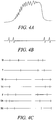
- Figure 4B shows a succession of breaths during a single therapy session.
- Figure 4C shows seven traces, one for each day of the week, with marks indicating when therapy sessions have taken place.
- Apparatus of the present invention can be used with any conventional respiratory therapy apparatus that produces a vibration.
- the therapy apparatus may be combined with other treatments such as nebulisation or the administration of aerosol medication.
- the present invention enables existing, conventional therapy apparatus that is known and trusted by the user and clinician to be readily modified to provide useful data about use of the apparatus.
- the user can be made more aware of how well he is complying with the prescribed therapy programme and can modify his use of the apparatus accordingly to achieve maximum benefit.
- the clinician is also able to check patient compliance so that he can identify whether any deterioration in a patient's condition is due to lack of compliance or if alternative treatment is needed.
Landscapes
- Health & Medical Sciences (AREA)
- General Health & Medical Sciences (AREA)
- Life Sciences & Earth Sciences (AREA)
- Pulmonology (AREA)
- Engineering & Computer Science (AREA)
- Public Health (AREA)
- Veterinary Medicine (AREA)
- Emergency Medicine (AREA)
- Animal Behavior & Ethology (AREA)
- Anesthesiology (AREA)
- Biomedical Technology (AREA)
- Heart & Thoracic Surgery (AREA)
- Hematology (AREA)
- Physical Education & Sports Medicine (AREA)
- Biophysics (AREA)
- Orthopedic Medicine & Surgery (AREA)
- Percussion Or Vibration Massage (AREA)
- Measurement Of The Respiration, Hearing Ability, Form, And Blood Characteristics Of Living Organisms (AREA)
Description
- This invention relates to respiratory therapy apparatus of the kind including a device having a structure and a movable member mounted with the structure and caused to oscillate by the action of breathing through the device such as to provide an oscillating resistance to breathing through the device.
- Positive expiratory pressure (PEP) apparatus, that is, apparatus that presents a resistance to expiration through the device, are now widely used to help treat patients suffering from a range of respiratory impairments, such as chronic obstructive pulmonary disease, bronchitis, cystic fibrosis and atelectasis. More recently, such apparatus that provide an alternating resistance to flow have been found to be particularly effective. One example of such apparatus is sold under the trade mark Acapella (a registered trade mark of Smiths Medical) by Smiths Medical and is described in
US6581598 ,US6776159 ,US7059324 andUS7699054 . Other vibratory respiratory therapy apparatus is available, such as "Quake" manufactured by Thayer, "AeroPEP" manufactured by Monaghan, "TheraPEP" manufactured by Smiths Medical and "IPV Percussionator" manufactured by Percussionaire Corp. Alternative apparatus such as "CoughAssist" manufactured by Philips is also available. Respiratory therapy apparatus can instead provide an alternating resistance to flow during inhalation.US6058932 describes a therapy device with an electrically-driven acoustic transducer. - To be effective these apparatus must be used regularly at prescribed intervals. In the case of chronic diseases, the patient needs to use the apparatus daily for the rest of his life in order to maintain continuous relief.
- Although these apparatus can be very effective, users often neglect to use the apparatus regularly at the prescribed frequency. It is very difficult to maintain a record of use of the apparatus, especially when the patient is using it at home. The clinician often does not know whether deterioration in a patient's condition is because he has failed to use the apparatus as prescribed or whether other factors are the cause.
- It is an object of the present invention to provide alternative respiratory therapy apparatus.
- According to the present invention there is provided a respiratory therapy apparatus of the above-specified kind, characterised in that the apparatus further includes a sensor mounted with the structure and responsive to vibration transmitted through the structure caused by the oscillating movement of the movable member to provide a signal indicative of the oscillatory movement of the movable member within the apparatus caused by breathing through the apparatus; and processing means arranged to convert the signal of the sensor into parameters indicative of the use of the vibratory therapy device whereby the sensor (20) includes an accelerometer (21).
- The structure preferably includes an outer housing of the device. The sensor is preferably mounted on the outside of the outer housing. The sensor may include a beam including a piezoelectric element, the beam being supported at one end such that vibration transmitted through the structure causes the beam to flex and produces a change of output from the piezoelectric element. The beam preferably supports a mass towards an opposite end. The device may include a store for storing the parameters. The apparatus may be arranged to provide an output representation from the parameters, the output representation being indicative of one or more of the following: when the apparatus is used, the duration of use and the quality of use of the apparatus. The apparatus may include a valve element on a rocker arm that opens and closes an opening during exhalation through the apparatus.
- Apparatus including a vibratory PEP device and its method of use according to the present invention will now be described, by way of example, with reference to the accompanying drawings, in which:
- Figure 1
- is an exploded view of the apparatus;
- Figure 2
- is a perspective view of the interior of the sensor;
- Figure 3
- illustrates an alternative form of sensor;
- Figure 4A
- illustrates the output from a single expiration;
- Figure 4B
- illustrates the output over a treatment cycle of multiple breaths; and
- Figure 4C
- illustrates use of the apparatus over a week.
- With reference first to
Figure 1 , therespiratory therapy device 100 comprises arocker assembly 1 contained within anouter housing 2 provided by anupper part 3 and alower part 4 of substantially semi-cylindrical shape. The device is completed by an adjustable dial 5 of circular section. Theouter housing 2 contains anair flow tube 6 with abreathing inlet 7 at one end and aninspiratory inlet 8 at the opposite end including a one-way valve (not shown) that allows air to flow into the air flow tube but prevents air flowing out through the inspiratory inlet. Theair flow tube 6 has an outlet opening 10 with a non-linear profile that is opened and closed by aconical valve element 11 mounted on arocker arm 12 pivoted midway along its length about a transverse axis. Theair flow tube 6 andhousing 2 provide a structure with which therocker arm 12 is mounted. At its far end, remote from thebreathing inlet 7, therocker arm 12 carries aniron pin 13 that interacts with the magnetic field produced by a permanent magnet (not visible) mounted on anadjustable support frame 14. The magnet arrangement is such that, when the patient is not breathing through the device, the far end of therocker arm 12 is held down such that itsvalve element 11 is also held down in sealing engagement with the outlet opening 10. Acam follower projection 15 at one end of thesupport frame 14 locates in acam slot 16 in the dial 5 such that, by rotating the dial, thesupport frame 14, with its magnet, can be moved up or down to alter the strength of the magnetic field interacting with theiron pin 13. The dial 5 enables the frequency of operation and the resistance to flow of air through the device to be adjusted for maximum therapeutic benefit to the user. - When the patient inhales through the
breathing inlet 7 air is drawn through theinspiratory inlet 8 and along theair flow tube 6 to the breathing inlet. When the patient exhales, the one-way valve in theinspiratory inlet 8 closes, preventing any air flowing out along this path. Instead, the expiratory pressure is applied to the underside of thevalve element 11 on therocker arm 12 causing it to be lifted up out of the opening 10 against the magnetic attraction, thereby allowing air to flow out to atmosphere. The opening 10 has a non-linear profile, which causes the effective discharge area to increase as the far end of therocker arm 12 lifts, thereby allowing the arm to fall back down and close the opening. As long as the user keeps applying sufficient expiratory pressure, therocker arm 12 will rise and fall repeatedly as theopening 10 is opened and closed, causing a vibratory, alternating or oscillating interruption to expiratory breath flow through the device. Further information about the construction and operation of the device can be found inUS6581598 , the contents of which are hereby incorporated into the present application. - As so far described, the device is conventional.
- The apparatus of the present invention includes the
device 100 described above and asensor 20 attached to the structure of the device. In particular, thesensor 20 is attached to the external surface of thehousing 2. Although it would be possible to mount thesensor 20 internally within thehousing 2, mounting the sensor externally avoids the need to provide electrical access within the device. Thesensor 20 is responsive to vibration transmitted through the structure of the device caused by parts of therocker arm 12 contacting other parts of the device as it oscillates up and down in seesaw fashion. Thesensor 20 is an accelerometer. Preferably, however, thesensor 20 includes apiezoelectric element 21 of the kind shown inFigure 2 . Thepiezoelectric element 21 is a model MiniSense 100NM or MiniSense 100 available from Measurement Specialities, although other piezoelectric sensors could be used. It includes a thin, bendable rectangular beam 22 that is itself of a piezoelectric material or includes a piezoelectric material bonded to a supporting substrate. The beam 22 is supported at oneend 23 in cantilever fashion by twopillars 24, which also act as electrodes to provide electrical connection to theelement 21, and hold the beam spaced above and parallel to acircuit board 25. The opposite,free end 26 of the beam 22 supports a small mass 27 so that any acceleration in the vertical plane causes the free end of the beam to flex up or down. This flexing of thepiezoelectric element 21 causes a charge or voltage to be produced across theoutput electrodes 24. Vibration transmitted through the structure provided by theair flow tube 6 and thehousing 2 causes thepiezoelectric element 21 to vibrate at a frequency and with an amplitude dependent on the frequency and magnitude (forcefulness) of oscillation of therocker arm 12. - The
sensor element 21 has a good linearity and dynamic range. The mass 27 may be modified to vary the frequency response and sensitivity. Theelement 21 may be used to detect either continuous or impulsive vibration or impacts. For excitation frequencies below its resonant frequency, thepiezoelectric element 21 produces a linear output governed by the "baseline" sensitivity. The sensitivity at resonance is significantly higher. Impacts containing high frequency components will excite the resonance frequency. The ability of thesensor element 21 to detect low frequency motion is strongly influenced by the external electrical circuit. - The output of the
piezoelectric element 21 is supplied to acircuit 29 on theboard 25, which is preferably anLDTC MiniSense 100 Analog PCB. Thecircuit 29 includes a low-power operational amplifier, comparator, DC/DC converter, store and passive components used in signal conditioning and has an adjustable gain. Thesensor 20 may itself include processing means or this may be provided externally in aunit 28. In particular, the processing is arranged to convert the output from thepiezoelectric element 21 into usable parameters by suitable statistical treatment, such as time-domain or frequency-domain analysis. Conventional signal processing using fast fourier transformation, correlation analysis, finite impulse filters and the like may be used. Thesensor 20 also includes a memory for recording the output and may also include a display for providing information to the patient, such as average frequency of vibration, day and time of the therapy sessions, duration of the therapy sessions and an indication of the quality of the exhalation breaths, representing the average pressure or flow as derived from the amplitude of the sensed vibration. The board also has anoutput socket 120, such as for a USB connector or may have a wireless output, such as using the Bluetooth radio frequency protocol. - Instead of being mounted on a circuit board, the piezoelectric element 21' could be encapsulated in a
protective capsule 30 as shown inFigure 3 . Thecapsule 30 includes little or no processing circuitry but has aconnector 31 by which connection can be made to a remote circuit at which the processing and storage can be carried out. - The typical output from the
piezoelectric element 21 during a single exhalation is shown inFigure 4A where the output rises along an approximate square wave with a superimposed alternating signal as the oscillation of therocker arm 12 becomes more forceful during the exhalation. When the user has exhausted his exhalation breath therocker arm 12 reverts to a stationary state with the outlet opening 10 closed. When this happens the output of thepiezoelectric element 21 rapidly falls. -
Figure 4B shows a succession of breaths during a single therapy session. -
Figure 4C shows seven traces, one for each day of the week, with marks indicating when therapy sessions have taken place. - It will be appreciated that there are many different ways in which information obtained from the sensor can be represented so that it is provided to the user and clinician in the most useful manner.
- Apparatus of the present invention can be used with any conventional respiratory therapy apparatus that produces a vibration. The therapy apparatus may be combined with other treatments such as nebulisation or the administration of aerosol medication.
- The present invention enables existing, conventional therapy apparatus that is known and trusted by the user and clinician to be readily modified to provide useful data about use of the apparatus. In this way, the user can be made more aware of how well he is complying with the prescribed therapy programme and can modify his use of the apparatus accordingly to achieve maximum benefit. The clinician is also able to check patient compliance so that he can identify whether any deterioration in a patient's condition is due to lack of compliance or if alternative treatment is needed.
Claims (8)
- Respiratory therapy apparatus including a vibratory therapy device (100) having a structure (2) and a movable member (12) mounted with the structure and caused to oscillate by the action of breathing through the device such as to provide an oscillating resistance to breathing through the device, whereby the apparatus further includes a sensor (20) mounted with the structure (2) and responsive to vibration transmitted through the structure caused by the oscillating movement of the movable member (12) to provide a signal indicative of the oscillatory movement of the movable member (12) within the apparatus caused by breathing through the apparatus; and processing means arranged to convert the signal of the sensor (20) into parameters indicative of the use of the vibratory therapy device (100), characterised in that the sensor (20) includes an accelerometer (21).
- Respiratory therapy apparatus according to Claim 1, wherein the structure includes an outer housing (2) of the device (100).
- Respiratory therapy apparatus according to Claim 2, wherein the sensor (20) is mounted on the outside of the outer housing (2).
- Respiratory therapy apparatus according to any one of the preceding claims, wherein the sensor (20) includes a beam (22) including a piezoelectric element (21), and wherein the beam (22) is supported at one end such that vibration transmitted through the structure (2) causes the beam (22) to flex and produces a change of output from the piezoelectric element (21).
- Respiratory therapy apparatus according to Claim 4, wherein the beam (22) supports a mass (27) towards an opposite end (26).
- Respiratory therapy apparatus according to any one of the preceding claims, wherein the apparatus includes a store (29) for storing the parameters.
- Respiratory therapy apparatus according to any one of the preceding claims, wherein the apparatus is arranged to provide an output representation from the parameters, and wherein the output representation is indicative of one or more of the following: when the apparatus is used, the duration of use and the quality of use of the apparatus.
- Respiratory therapy apparatus according to any one of the preceding claims, wherein device (100) includes a valve element (11) on a rocker arm (12) that opens and closes an opening (10) during exhalation through the apparatus.
Applications Claiming Priority (2)
| Application Number | Priority Date | Filing Date | Title |
|---|---|---|---|
| GBGB1310826.1A GB201310826D0 (en) | 2013-06-18 | 2013-06-18 | Respiratory therapy apparatus and methods |
| PCT/GB2014/000184 WO2014202924A1 (en) | 2013-06-18 | 2014-05-14 | Respiratory therapy apparatus and methods |
Publications (3)
| Publication Number | Publication Date |
|---|---|
| EP3010397A1 EP3010397A1 (en) | 2016-04-27 |
| EP3010397B1 EP3010397B1 (en) | 2019-04-10 |
| EP3010397B2 true EP3010397B2 (en) | 2021-09-15 |
Family
ID=48914734
Family Applications (1)
| Application Number | Title | Priority Date | Filing Date |
|---|---|---|---|
| EP14727016.9A Active EP3010397B2 (en) | 2013-06-18 | 2014-05-14 | Respiratory therapy apparatus and methods |
Country Status (6)
| Country | Link |
|---|---|
| US (1) | US11000654B2 (en) |
| EP (1) | EP3010397B2 (en) |
| JP (1) | JP6503595B2 (en) |
| CA (1) | CA2910134C (en) |
| GB (1) | GB201310826D0 (en) |
| WO (1) | WO2014202924A1 (en) |
Families Citing this family (27)
| Publication number | Priority date | Publication date | Assignee | Title |
|---|---|---|---|---|
| US9517315B2 (en) | 2012-11-30 | 2016-12-13 | Trudell Medical International | Oscillating positive expiratory pressure device |
| EP3019137B1 (en) | 2013-07-12 | 2019-02-06 | Trudell Medical International | Huff cough simulation device |
| US9849257B2 (en) | 2013-08-22 | 2017-12-26 | Trudell Medical International | Oscillating positive respiratory pressure device |
| GB201420518D0 (en) | 2014-11-19 | 2014-12-31 | Smiths Medical Int Ltd | Respiratory therapy apparatus |
| FR3038519B1 (en) * | 2015-07-10 | 2022-03-18 | Lantz Jean Sebastien | TRACHEO-BRONCHIAL AIR STIMULATING DEVICE |
| ES2855373T3 (en) | 2015-12-04 | 2021-09-23 | Trudell Medical Int | Forced Expiration Cough Simulation Device |
| CN109152891B (en) | 2016-03-24 | 2022-11-08 | 特鲁德尔医学国际公司 | Respiratory care system with electronic indicator |
| GB201608128D0 (en) * | 2016-05-07 | 2016-06-22 | Smiths Medical Int Ltd | Respiratory monitoring apparatus |
| US9914017B2 (en) * | 2016-05-17 | 2018-03-13 | Patrick McKeown | Sports mask system |
| ES2966349T3 (en) | 2016-05-19 | 2024-04-22 | Trudell Medical Int | Holding chamber with smart valve |
| ES2988939T3 (en) | 2016-07-08 | 2024-11-22 | Trudell Medical Int Inc | Intelligent Oscillating Positive Expiratory Pressure Device |
| CN110049795B (en) | 2016-12-09 | 2022-07-19 | 特鲁德尔医学国际公司 | Intelligent atomizer |
| US10506926B2 (en) | 2017-02-18 | 2019-12-17 | Arc Devices Limited | Multi-vital sign detector in an electronic medical records system |
| US10492684B2 (en) | 2017-02-21 | 2019-12-03 | Arc Devices Limited | Multi-vital-sign smartphone system in an electronic medical records system |
| CA3059532C (en) | 2017-05-03 | 2024-10-01 | Trudell Medical International Inc. | Combined oscillating positive expiratory pressure therapy and huff cough simulation device |
| US10602987B2 (en) | 2017-08-10 | 2020-03-31 | Arc Devices Limited | Multi-vital-sign smartphone system in an electronic medical records system |
| US11666801B2 (en) | 2018-01-04 | 2023-06-06 | Trudell Medical International | Smart oscillating positive expiratory pressure device |
| KR102168758B1 (en) * | 2018-01-16 | 2020-10-22 | 연세대학교 원주산학협력단 | Portable respiration training device system and thereof methods with training function to strengthen respiratory muscles |
| US10485431B1 (en) | 2018-05-21 | 2019-11-26 | ARC Devices Ltd. | Glucose multi-vital-sign system in an electronic medical records system |
| EP3801714B1 (en) | 2018-06-04 | 2026-01-28 | Trudell Medical International Inc. | Smart valved holding chamber |
| GB201809559D0 (en) * | 2018-06-09 | 2018-07-25 | Smiths Medical International Ltd | Respiratory therapy apparatus and methods |
| GB201904825D0 (en) | 2019-04-05 | 2019-05-22 | Smiths Medical International Ltd | Respiratory therapy apparatus |
| WO2021038467A1 (en) | 2019-08-27 | 2021-03-04 | Trudell Medical International | Smart oscillating positive expiratory pressure device |
| WO2021247300A1 (en) | 2020-06-01 | 2021-12-09 | Arc Devices Limited | Apparatus and methods for measuring blood pressure and other vital signs via a finger |
| IT202100012089A1 (en) * | 2021-05-11 | 2022-11-11 | Milano Politecnico | Device for analysis/monitoring and training of the respiratory system |
| CN113648619A (en) * | 2021-09-26 | 2021-11-16 | 重庆上品益生电子商务有限公司 | breathing trainer |
| CA3258274A1 (en) | 2022-06-03 | 2023-12-07 | Mark Haig Khachaturian | Apparatus and methods for measuring blood pressure and other vital signs via a finger |
Family Cites Families (38)
| Publication number | Priority date | Publication date | Assignee | Title |
|---|---|---|---|---|
| US3640133A (en) * | 1967-02-24 | 1972-02-08 | Moore Products Co | Flowmeter |
| AU607164B2 (en) | 1987-10-22 | 1991-02-28 | Varioraw Percutive S.A. | Expiration resistance apparatus for improving the pulmonary ventilation |
| CH685475A5 (en) | 1992-04-10 | 1995-07-31 | Varioraw Percutive Sa | specific therapeutic device in the respiratory field. |
| US5544647A (en) * | 1994-11-29 | 1996-08-13 | Iep Group, Inc. | Metered dose inhalator |
| US6058932A (en) * | 1997-04-21 | 2000-05-09 | Hughes; Arthur R. | Acoustic transceiver respiratory therapy apparatus |
| AUPO826597A0 (en) | 1997-07-25 | 1997-08-21 | Platt, Harry Louis | Cardiac patient remote monitoring apparatus |
| US6076392A (en) * | 1997-08-18 | 2000-06-20 | Metasensors, Inc. | Method and apparatus for real time gas analysis |
| US6328033B1 (en) * | 1999-06-04 | 2001-12-11 | Zohar Avrahami | Powder inhaler |
| US6581596B1 (en) * | 1999-09-24 | 2003-06-24 | Respironics, Inc. | Apparatus and method of providing high frequency variable pressure to a patient |
| US6776159B2 (en) * | 1999-11-24 | 2004-08-17 | Dhd Healthcare Corporation | Positive expiratory pressure device with bypass |
| US6581598B1 (en) | 1999-11-24 | 2003-06-24 | Dhd Healthcare Corporation | Positive expiratory pressure device |
| US7059324B2 (en) * | 1999-11-24 | 2006-06-13 | Smiths Medical Asd, Inc. | Positive expiratory pressure device with bypass |
| GB0204328D0 (en) | 2002-02-25 | 2002-04-10 | Fyne Dynamics Ltd | Flow indicator |
| WO2003077511A1 (en) | 2002-03-12 | 2003-09-18 | Era Centre Pty Ltd | Multifunctional mobile phone for medical diagnosis and rehabilitation |
| JP3902506B2 (en) * | 2002-05-16 | 2007-04-11 | セイコーインスツル株式会社 | Portable biological information collection device |
| DE10253934C1 (en) * | 2002-11-19 | 2003-12-04 | Seleon Gmbh | Continuous positive airway pressure respiration device with selective illumination of display and/or operating controls under control of sensor signal |
| US6910481B2 (en) | 2003-03-28 | 2005-06-28 | Ric Investments, Inc. | Pressure support compliance monitoring system |
| US20070089740A1 (en) | 2003-04-28 | 2007-04-26 | Chi, Llc | Pursed lip breathing device |
| JPWO2005016426A1 (en) * | 2003-08-14 | 2006-10-12 | 帝人ファーマ株式会社 | Oxygen concentrator and home oxygen therapy execution support method using the same |
| US20060212273A1 (en) | 2005-03-04 | 2006-09-21 | Individual Monitoring Systems.Inc. | Real-time snoring assessment apparatus and method |
| US20080078384A1 (en) * | 2006-09-18 | 2008-04-03 | Invacare Corporation | Breathing gas delivery system with user feedback |
| US8225785B2 (en) * | 2006-10-03 | 2012-07-24 | Smiths Medical Asd, Inc. | Vibratory PEP therapy system with medicated aerosol nebulizer |
| US20090030285A1 (en) | 2007-07-25 | 2009-01-29 | Andersen Bjorn K | Monitoring of use status and automatic power management in medical devices |
| KR101628410B1 (en) * | 2008-06-20 | 2016-06-08 | 맨카인드 코포레이션 | An interactive apparatus and method for real-time profiling of inhalation efforts |
| GB2469068B (en) * | 2009-03-31 | 2011-03-09 | Naseem Bari | Usage indicator |
| JP5852961B2 (en) * | 2009-10-28 | 2016-02-03 | コーニンクレッカ フィリップス エヌ ヴェKoninklijke Philips N.V. | Pressure assist system with guide tube |
| US20110100112A1 (en) * | 2009-10-30 | 2011-05-05 | Schlumberger Technology Corporation | Piezo-based downhole flow meter |
| WO2011056889A1 (en) * | 2009-11-03 | 2011-05-12 | Mannkind Corporation | An apparatus and method for simulating inhalation efforts |
| US8758262B2 (en) | 2009-11-25 | 2014-06-24 | University Of Rochester | Respiratory disease monitoring system |
| CA2808836C (en) | 2010-08-23 | 2020-05-12 | Darren Rubin | Systems and methods of aerosol delivery with airflow regulation |
| WO2012038903A2 (en) | 2010-09-22 | 2012-03-29 | Lior Gonnen | Modular acoustic spirometer |
| US8844537B1 (en) * | 2010-10-13 | 2014-09-30 | Michael T. Abramson | System and method for alleviating sleep apnea |
| WO2012058727A2 (en) * | 2010-11-05 | 2012-05-10 | Resmed Limited | Acoustic detection mask systems and/or methods |
| CN103370005A (en) * | 2010-12-20 | 2013-10-23 | 皇家飞利浦电子股份有限公司 | System and method of providing feedback to a subject receiving respiratory therapy via a client device associated with the subject |
| WO2012095764A1 (en) * | 2011-01-14 | 2012-07-19 | Koninklijke Philips Electronics N.V. | Measuring continuity of therapy associated with a respiratory treatment device |
| FR2970872B1 (en) * | 2011-02-02 | 2014-04-11 | Air Liquide | DEVICE FOR MEASURING THE OBSERVANCE OF TREATMENT OF THREE DIMENSIONAL ACCELEROMETER OXYGEN THERAPY |
| GB201209962D0 (en) * | 2012-06-06 | 2012-07-18 | Smiths Medical Int Ltd | Respiratory therapy apparatus |
| US8807131B1 (en) * | 2013-06-18 | 2014-08-19 | Isonea Limited | Compliance monitoring for asthma inhalers |
-
2013
- 2013-06-18 GB GBGB1310826.1A patent/GB201310826D0/en not_active Ceased
-
2014
- 2014-05-14 EP EP14727016.9A patent/EP3010397B2/en active Active
- 2014-05-14 WO PCT/GB2014/000184 patent/WO2014202924A1/en not_active Ceased
- 2014-05-14 JP JP2016520733A patent/JP6503595B2/en active Active
- 2014-05-14 US US14/898,159 patent/US11000654B2/en active Active
- 2014-05-14 CA CA2910134A patent/CA2910134C/en active Active
Also Published As
| Publication number | Publication date |
|---|---|
| GB201310826D0 (en) | 2013-07-31 |
| JP2016523636A (en) | 2016-08-12 |
| CA2910134C (en) | 2022-02-22 |
| EP3010397A1 (en) | 2016-04-27 |
| JP6503595B2 (en) | 2019-04-24 |
| CA2910134A1 (en) | 2014-12-24 |
| EP3010397B1 (en) | 2019-04-10 |
| US20160136367A1 (en) | 2016-05-19 |
| US11000654B2 (en) | 2021-05-11 |
| WO2014202924A1 (en) | 2014-12-24 |
Similar Documents
| Publication | Publication Date | Title |
|---|---|---|
| EP3010397B2 (en) | Respiratory therapy apparatus and methods | |
| EP3010396B2 (en) | Respiratory therapy apparatus | |
| JP6957520B2 (en) | Holding chamber with smart valve | |
| US20160213868A1 (en) | Respiratory therapy apparatus and methods | |
| CN105579104A (en) | Respiratory therapy apparatus, sensors and methods | |
| US10675422B2 (en) | Monitoring respiratory parameters through ultrasonic measurements indicating flow changes in respiratory drug delivery devices | |
| US20170020776A1 (en) | Respiratory therapy systems, sensors arrangements and methods | |
| US20160166785A1 (en) | Monitoring of nebulizer usage | |
| IL316543A (en) | Compliance Monitoring Unit for Inhaler | |
| WO2016049066A1 (en) | Vibration sensor based drug delivery monitor | |
| US10799655B2 (en) | Ultrasonic energy measurements in respiratory drug delivery devices | |
| WO2017187116A1 (en) | Respiratory therapy apparatus | |
| US10946151B2 (en) | Ultrasonic measurements for monitoring patients using respiratory therapy delivery devices | |
| EP3946530B1 (en) | Respiratory therapy apparatus | |
| GB2560105A (en) | Respiratory therapy apparatus |
Legal Events
| Date | Code | Title | Description |
|---|---|---|---|
| PUAI | Public reference made under article 153(3) epc to a published international application that has entered the european phase |
Free format text: ORIGINAL CODE: 0009012 |
|
| 17P | Request for examination filed |
Effective date: 20160210 |
|
| AK | Designated contracting states |
Kind code of ref document: A1 Designated state(s): AL AT BE BG CH CY CZ DE DK EE ES FI FR GB GR HR HU IE IS IT LI LT LU LV MC MK MT NL NO PL PT RO RS SE SI SK SM TR |
|
| AX | Request for extension of the european patent |
Extension state: BA ME |
|
| DAX | Request for extension of the european patent (deleted) | ||
| STAA | Information on the status of an ep patent application or granted ep patent |
Free format text: STATUS: EXAMINATION IS IN PROGRESS |
|
| 17Q | First examination report despatched |
Effective date: 20170217 |
|
| GRAP | Despatch of communication of intention to grant a patent |
Free format text: ORIGINAL CODE: EPIDOSNIGR1 |
|
| STAA | Information on the status of an ep patent application or granted ep patent |
Free format text: STATUS: GRANT OF PATENT IS INTENDED |
|
| INTG | Intention to grant announced |
Effective date: 20181211 |
|
| GRAS | Grant fee paid |
Free format text: ORIGINAL CODE: EPIDOSNIGR3 |
|
| GRAA | (expected) grant |
Free format text: ORIGINAL CODE: 0009210 |
|
| STAA | Information on the status of an ep patent application or granted ep patent |
Free format text: STATUS: THE PATENT HAS BEEN GRANTED |
|
| AK | Designated contracting states |
Kind code of ref document: B1 Designated state(s): AL AT BE BG CH CY CZ DE DK EE ES FI FR GB GR HR HU IE IS IT LI LT LU LV MC MK MT NL NO PL PT RO RS SE SI SK SM TR |
|
| REG | Reference to a national code |
Ref country code: GB Ref legal event code: FG4D |
|
| REG | Reference to a national code |
Ref country code: CH Ref legal event code: EP Ref country code: AT Ref legal event code: REF Ref document number: 1117567 Country of ref document: AT Kind code of ref document: T Effective date: 20190415 |
|
| REG | Reference to a national code |
Ref country code: IE Ref legal event code: FG4D |
|
| REG | Reference to a national code |
Ref country code: DE Ref legal event code: R096 Ref document number: 602014044416 Country of ref document: DE |
|
| REG | Reference to a national code |
Ref country code: NL Ref legal event code: MP Effective date: 20190410 |
|
| REG | Reference to a national code |
Ref country code: LT Ref legal event code: MG4D |
|
| REG | Reference to a national code |
Ref country code: AT Ref legal event code: MK05 Ref document number: 1117567 Country of ref document: AT Kind code of ref document: T Effective date: 20190410 |
|
| PG25 | Lapsed in a contracting state [announced via postgrant information from national office to epo] |
Ref country code: NL Free format text: LAPSE BECAUSE OF FAILURE TO SUBMIT A TRANSLATION OF THE DESCRIPTION OR TO PAY THE FEE WITHIN THE PRESCRIBED TIME-LIMIT Effective date: 20190410 |
|
| PG25 | Lapsed in a contracting state [announced via postgrant information from national office to epo] |
Ref country code: FI Free format text: LAPSE BECAUSE OF FAILURE TO SUBMIT A TRANSLATION OF THE DESCRIPTION OR TO PAY THE FEE WITHIN THE PRESCRIBED TIME-LIMIT Effective date: 20190410 Ref country code: AL Free format text: LAPSE BECAUSE OF FAILURE TO SUBMIT A TRANSLATION OF THE DESCRIPTION OR TO PAY THE FEE WITHIN THE PRESCRIBED TIME-LIMIT Effective date: 20190410 Ref country code: SE Free format text: LAPSE BECAUSE OF FAILURE TO SUBMIT A TRANSLATION OF THE DESCRIPTION OR TO PAY THE FEE WITHIN THE PRESCRIBED TIME-LIMIT Effective date: 20190410 Ref country code: PT Free format text: LAPSE BECAUSE OF FAILURE TO SUBMIT A TRANSLATION OF THE DESCRIPTION OR TO PAY THE FEE WITHIN THE PRESCRIBED TIME-LIMIT Effective date: 20190910 Ref country code: NO Free format text: LAPSE BECAUSE OF FAILURE TO SUBMIT A TRANSLATION OF THE DESCRIPTION OR TO PAY THE FEE WITHIN THE PRESCRIBED TIME-LIMIT Effective date: 20190710 Ref country code: HR Free format text: LAPSE BECAUSE OF FAILURE TO SUBMIT A TRANSLATION OF THE DESCRIPTION OR TO PAY THE FEE WITHIN THE PRESCRIBED TIME-LIMIT Effective date: 20190410 Ref country code: LT Free format text: LAPSE BECAUSE OF FAILURE TO SUBMIT A TRANSLATION OF THE DESCRIPTION OR TO PAY THE FEE WITHIN THE PRESCRIBED TIME-LIMIT Effective date: 20190410 Ref country code: ES Free format text: LAPSE BECAUSE OF FAILURE TO SUBMIT A TRANSLATION OF THE DESCRIPTION OR TO PAY THE FEE WITHIN THE PRESCRIBED TIME-LIMIT Effective date: 20190410 |
|
| PG25 | Lapsed in a contracting state [announced via postgrant information from national office to epo] |
Ref country code: LV Free format text: LAPSE BECAUSE OF FAILURE TO SUBMIT A TRANSLATION OF THE DESCRIPTION OR TO PAY THE FEE WITHIN THE PRESCRIBED TIME-LIMIT Effective date: 20190410 Ref country code: RS Free format text: LAPSE BECAUSE OF FAILURE TO SUBMIT A TRANSLATION OF THE DESCRIPTION OR TO PAY THE FEE WITHIN THE PRESCRIBED TIME-LIMIT Effective date: 20190410 Ref country code: BG Free format text: LAPSE BECAUSE OF FAILURE TO SUBMIT A TRANSLATION OF THE DESCRIPTION OR TO PAY THE FEE WITHIN THE PRESCRIBED TIME-LIMIT Effective date: 20190710 Ref country code: GR Free format text: LAPSE BECAUSE OF FAILURE TO SUBMIT A TRANSLATION OF THE DESCRIPTION OR TO PAY THE FEE WITHIN THE PRESCRIBED TIME-LIMIT Effective date: 20190711 Ref country code: PL Free format text: LAPSE BECAUSE OF FAILURE TO SUBMIT A TRANSLATION OF THE DESCRIPTION OR TO PAY THE FEE WITHIN THE PRESCRIBED TIME-LIMIT Effective date: 20190410 |
|
| REG | Reference to a national code |
Ref country code: CH Ref legal event code: PL |
|
| PG25 | Lapsed in a contracting state [announced via postgrant information from national office to epo] |
Ref country code: IS Free format text: LAPSE BECAUSE OF FAILURE TO SUBMIT A TRANSLATION OF THE DESCRIPTION OR TO PAY THE FEE WITHIN THE PRESCRIBED TIME-LIMIT Effective date: 20190810 Ref country code: AT Free format text: LAPSE BECAUSE OF FAILURE TO SUBMIT A TRANSLATION OF THE DESCRIPTION OR TO PAY THE FEE WITHIN THE PRESCRIBED TIME-LIMIT Effective date: 20190410 |
|
| REG | Reference to a national code |
Ref country code: DE Ref legal event code: R026 Ref document number: 602014044416 Country of ref document: DE |
|
| PLBI | Opposition filed |
Free format text: ORIGINAL CODE: 0009260 |
|
| PLAX | Notice of opposition and request to file observation + time limit sent |
Free format text: ORIGINAL CODE: EPIDOSNOBS2 |
|
| PG25 | Lapsed in a contracting state [announced via postgrant information from national office to epo] |
Ref country code: MC Free format text: LAPSE BECAUSE OF FAILURE TO SUBMIT A TRANSLATION OF THE DESCRIPTION OR TO PAY THE FEE WITHIN THE PRESCRIBED TIME-LIMIT Effective date: 20190410 Ref country code: SK Free format text: LAPSE BECAUSE OF FAILURE TO SUBMIT A TRANSLATION OF THE DESCRIPTION OR TO PAY THE FEE WITHIN THE PRESCRIBED TIME-LIMIT Effective date: 20190410 Ref country code: DK Free format text: LAPSE BECAUSE OF FAILURE TO SUBMIT A TRANSLATION OF THE DESCRIPTION OR TO PAY THE FEE WITHIN THE PRESCRIBED TIME-LIMIT Effective date: 20190410 Ref country code: CH Free format text: LAPSE BECAUSE OF NON-PAYMENT OF DUE FEES Effective date: 20190531 Ref country code: LI Free format text: LAPSE BECAUSE OF NON-PAYMENT OF DUE FEES Effective date: 20190531 Ref country code: EE Free format text: LAPSE BECAUSE OF FAILURE TO SUBMIT A TRANSLATION OF THE DESCRIPTION OR TO PAY THE FEE WITHIN THE PRESCRIBED TIME-LIMIT Effective date: 20190410 Ref country code: RO Free format text: LAPSE BECAUSE OF FAILURE TO SUBMIT A TRANSLATION OF THE DESCRIPTION OR TO PAY THE FEE WITHIN THE PRESCRIBED TIME-LIMIT Effective date: 20190410 Ref country code: CZ Free format text: LAPSE BECAUSE OF FAILURE TO SUBMIT A TRANSLATION OF THE DESCRIPTION OR TO PAY THE FEE WITHIN THE PRESCRIBED TIME-LIMIT Effective date: 20190410 |
|
| REG | Reference to a national code |
Ref country code: BE Ref legal event code: MM Effective date: 20190531 |
|
| 26 | Opposition filed |
Opponent name: TRUDELL MEDICAL LTD. Effective date: 20200110 |
|
| PG25 | Lapsed in a contracting state [announced via postgrant information from national office to epo] |
Ref country code: LU Free format text: LAPSE BECAUSE OF NON-PAYMENT OF DUE FEES Effective date: 20190514 Ref country code: SM Free format text: LAPSE BECAUSE OF FAILURE TO SUBMIT A TRANSLATION OF THE DESCRIPTION OR TO PAY THE FEE WITHIN THE PRESCRIBED TIME-LIMIT Effective date: 20190410 Ref country code: IT Free format text: LAPSE BECAUSE OF FAILURE TO SUBMIT A TRANSLATION OF THE DESCRIPTION OR TO PAY THE FEE WITHIN THE PRESCRIBED TIME-LIMIT Effective date: 20190410 |
|
| PG25 | Lapsed in a contracting state [announced via postgrant information from national office to epo] |
Ref country code: TR Free format text: LAPSE BECAUSE OF FAILURE TO SUBMIT A TRANSLATION OF THE DESCRIPTION OR TO PAY THE FEE WITHIN THE PRESCRIBED TIME-LIMIT Effective date: 20190410 |
|
| PG25 | Lapsed in a contracting state [announced via postgrant information from national office to epo] |
Ref country code: IE Free format text: LAPSE BECAUSE OF NON-PAYMENT OF DUE FEES Effective date: 20190514 |
|
| PG25 | Lapsed in a contracting state [announced via postgrant information from national office to epo] |
Ref country code: SI Free format text: LAPSE BECAUSE OF FAILURE TO SUBMIT A TRANSLATION OF THE DESCRIPTION OR TO PAY THE FEE WITHIN THE PRESCRIBED TIME-LIMIT Effective date: 20190410 Ref country code: BE Free format text: LAPSE BECAUSE OF NON-PAYMENT OF DUE FEES Effective date: 20190531 |
|
| PLBB | Reply of patent proprietor to notice(s) of opposition received |
Free format text: ORIGINAL CODE: EPIDOSNOBS3 |
|
| PLAB | Opposition data, opponent's data or that of the opponent's representative modified |
Free format text: ORIGINAL CODE: 0009299OPPO |
|
| R26 | Opposition filed (corrected) |
Opponent name: TRUDELL MEDICAL INTERNATIONAL Effective date: 20200110 |
|
| PG25 | Lapsed in a contracting state [announced via postgrant information from national office to epo] |
Ref country code: CY Free format text: LAPSE BECAUSE OF FAILURE TO SUBMIT A TRANSLATION OF THE DESCRIPTION OR TO PAY THE FEE WITHIN THE PRESCRIBED TIME-LIMIT Effective date: 20190410 |
|
| PG25 | Lapsed in a contracting state [announced via postgrant information from national office to epo] |
Ref country code: HU Free format text: LAPSE BECAUSE OF FAILURE TO SUBMIT A TRANSLATION OF THE DESCRIPTION OR TO PAY THE FEE WITHIN THE PRESCRIBED TIME-LIMIT; INVALID AB INITIO Effective date: 20140514 Ref country code: MT Free format text: LAPSE BECAUSE OF FAILURE TO SUBMIT A TRANSLATION OF THE DESCRIPTION OR TO PAY THE FEE WITHIN THE PRESCRIBED TIME-LIMIT Effective date: 20190410 |
|
| PUAH | Patent maintained in amended form |
Free format text: ORIGINAL CODE: 0009272 |
|
| STAA | Information on the status of an ep patent application or granted ep patent |
Free format text: STATUS: PATENT MAINTAINED AS AMENDED |
|
| 27A | Patent maintained in amended form |
Effective date: 20210915 |
|
| AK | Designated contracting states |
Kind code of ref document: B2 Designated state(s): AL AT BE BG CH CY CZ DE DK EE ES FI FR GB GR HR HU IE IS IT LI LT LU LV MC MK MT NL NO PL PT RO RS SE SI SK SM TR |
|
| REG | Reference to a national code |
Ref country code: DE Ref legal event code: R102 Ref document number: 602014044416 Country of ref document: DE |
|
| PG25 | Lapsed in a contracting state [announced via postgrant information from national office to epo] |
Ref country code: MK Free format text: LAPSE BECAUSE OF FAILURE TO SUBMIT A TRANSLATION OF THE DESCRIPTION OR TO PAY THE FEE WITHIN THE PRESCRIBED TIME-LIMIT Effective date: 20190410 |
|
| P01 | Opt-out of the competence of the unified patent court (upc) registered |
Effective date: 20230419 |
|
| REG | Reference to a national code |
Ref country code: DE Ref legal event code: R081 Ref document number: 602014044416 Country of ref document: DE Owner name: ICU MEDICAL INTERNATIONAL LTD., ASHFORD, GB Free format text: FORMER OWNER: SMITHS MEDICAL INTERNATIONAL LTD., ASHFORD, KENT, GB |
|
| PGFP | Annual fee paid to national office [announced via postgrant information from national office to epo] |
Ref country code: DE Payment date: 20250319 Year of fee payment: 12 |
|
| PGFP | Annual fee paid to national office [announced via postgrant information from national office to epo] |
Ref country code: GB Payment date: 20260312 Year of fee payment: 13 |
|
| PGFP | Annual fee paid to national office [announced via postgrant information from national office to epo] |
Ref country code: FR Payment date: 20260309 Year of fee payment: 13 |