EP3010307A1 - Inductive heating energy recovery system - Google Patents
Inductive heating energy recovery system Download PDFInfo
- Publication number
- EP3010307A1 EP3010307A1 EP15189902.8A EP15189902A EP3010307A1 EP 3010307 A1 EP3010307 A1 EP 3010307A1 EP 15189902 A EP15189902 A EP 15189902A EP 3010307 A1 EP3010307 A1 EP 3010307A1
- Authority
- EP
- European Patent Office
- Prior art keywords
- inductive heating
- recovery system
- energy recovery
- steam
- pump
- Prior art date
- Legal status (The legal status is an assumption and is not a legal conclusion. Google has not performed a legal analysis and makes no representation as to the accuracy of the status listed.)
- Granted
Links
Images


Classifications
-
- F—MECHANICAL ENGINEERING; LIGHTING; HEATING; WEAPONS; BLASTING
- F22—STEAM GENERATION
- F22B—METHODS OF STEAM GENERATION; STEAM BOILERS
- F22B1/00—Methods of steam generation characterised by form of heating method
- F22B1/28—Methods of steam generation characterised by form of heating method in boilers heated electrically
- F22B1/281—Methods of steam generation characterised by form of heating method in boilers heated electrically other than by electrical resistances or electrodes
-
- B—PERFORMING OPERATIONS; TRANSPORTING
- B23—MACHINE TOOLS; METAL-WORKING NOT OTHERWISE PROVIDED FOR
- B23K—SOLDERING OR UNSOLDERING; WELDING; CLADDING OR PLATING BY SOLDERING OR WELDING; CUTTING BY APPLYING HEAT LOCALLY, e.g. FLAME CUTTING; WORKING BY LASER BEAM
- B23K26/00—Working by laser beam, e.g. welding, cutting or boring
- B23K26/20—Bonding
- B23K26/32—Bonding taking account of the properties of the material involved
- B23K26/322—Bonding taking account of the properties of the material involved involving coated metal parts
-
- H—ELECTRICITY
- H05—ELECTRIC TECHNIQUES NOT OTHERWISE PROVIDED FOR
- H05B—ELECTRIC HEATING; ELECTRIC LIGHT SOURCES NOT OTHERWISE PROVIDED FOR; CIRCUIT ARRANGEMENTS FOR ELECTRIC LIGHT SOURCES, IN GENERAL
- H05B6/00—Heating by electric, magnetic or electromagnetic fields
- H05B6/02—Induction heating
- H05B6/10—Induction heating apparatus, other than furnaces, for specific applications
- H05B6/105—Induction heating apparatus, other than furnaces, for specific applications using a susceptor
- H05B6/108—Induction heating apparatus, other than furnaces, for specific applications using a susceptor for heating a fluid
-
- H—ELECTRICITY
- H05—ELECTRIC TECHNIQUES NOT OTHERWISE PROVIDED FOR
- H05B—ELECTRIC HEATING; ELECTRIC LIGHT SOURCES NOT OTHERWISE PROVIDED FOR; CIRCUIT ARRANGEMENTS FOR ELECTRIC LIGHT SOURCES, IN GENERAL
- H05B6/00—Heating by electric, magnetic or electromagnetic fields
- H05B6/02—Induction heating
- H05B6/36—Coil arrangements
- H05B6/42—Cooling of coils
-
- B—PERFORMING OPERATIONS; TRANSPORTING
- B23—MACHINE TOOLS; METAL-WORKING NOT OTHERWISE PROVIDED FOR
- B23K—SOLDERING OR UNSOLDERING; WELDING; CLADDING OR PLATING BY SOLDERING OR WELDING; CUTTING BY APPLYING HEAT LOCALLY, e.g. FLAME CUTTING; WORKING BY LASER BEAM
- B23K26/00—Working by laser beam, e.g. welding, cutting or boring
- B23K26/36—Removing material
- B23K26/361—Removing material for deburring or mechanical trimming
-
- B—PERFORMING OPERATIONS; TRANSPORTING
- B23—MACHINE TOOLS; METAL-WORKING NOT OTHERWISE PROVIDED FOR
- B23K—SOLDERING OR UNSOLDERING; WELDING; CLADDING OR PLATING BY SOLDERING OR WELDING; CUTTING BY APPLYING HEAT LOCALLY, e.g. FLAME CUTTING; WORKING BY LASER BEAM
- B23K26/00—Working by laser beam, e.g. welding, cutting or boring
- B23K26/36—Removing material
- B23K26/362—Laser etching
-
- H—ELECTRICITY
- H05—ELECTRIC TECHNIQUES NOT OTHERWISE PROVIDED FOR
- H05B—ELECTRIC HEATING; ELECTRIC LIGHT SOURCES NOT OTHERWISE PROVIDED FOR; CIRCUIT ARRANGEMENTS FOR ELECTRIC LIGHT SOURCES, IN GENERAL
- H05B2214/00—Aspects relating to resistive heating, induction heating and heating using microwaves, covered by groups H05B3/00, H05B6/00
- H05B2214/03—Heating of hydrocarbons
Definitions
- the present disclosure relates to induction heating systems, and, more specifically, to an oil-cooled induction heating system to recover heat energy.
- Induction heating may be used in manufacturing carbon brake parts. Induction heating may consume a large amount of energy to operate in vacuum vessels used in the heating process. At the same time, copper coils used in conventional inductive methods consume electricity and generate heat both in the copper coils and inside of the vessel. The copper coils may be cooled using a variety of methods. However, significant heat energy may leave the system as heat waste as a result of cooling the coils. For example, steam may be evaporated into the atmosphere after cooling the coils. As a result, induction heating operations may leave a large carbon emissions footprint. Furthermore, water cooled induction heating systems may have unacceptably high pressure in the induction coils as the induction coil gets hot and water begins to boil or evaporate.
- the energy recovery system may comprise an inductive heating coil configured to have a cooling fluid flow through the inductive heating coil and a heat exchanger fluidly coupled to the inductive heating coil and configured to produce a steam source.
- the steam source drives a pump.
- the cooling fluid may comprise a liquid-phase heat transfer fluid.
- the pump may further comprise a steam turbine pump.
- the pump may comprise a vacuum pump.
- the inductive heating coil may comprise copper tubing.
- a steam header may contain the steam source and be in fluid communication with the heat exchanger.
- a variable frequency drive pump may be fluidly coupled to the inductive heating coil.
- a ceramic insulating material may be in contact with the inductive heating coil.
- a fluid storage tank may be configured to store the cooling fluid.
- the inductive heating device may comprise a conductive coil, an insulating material proximate the conductive coil, a susceptor proximate the insulating material, and a heat transfer oil in the conductive coil.
- a heat exchanger may be configured to cool the heat transfer oil and produce steam.
- a vacuum pump may be configured to be driven by the steam.
- the heat exchanger may use water to cool the heat transfer oil.
- a variable frequency drive pump may be configured to move the heat transfer oil into the conductive coil.
- a steam turbine pump may be configured to move the heat transfer oil into the conductive coil.
- any reference to singular includes plural embodiments, and any reference to more than one component or step may include a singular embodiment or step.
- any reference to attached, fixed, connected or the like may include permanent, removable, temporary, partial, full and/or any other possible attachment option.
- any reference to without contact (or similar phrases) may also include reduced contact or minimal contact. Surface shading lines may be used throughout the figures to denote different parts but not necessarily to denote the same or different materials.
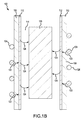
- FIG. 1B illustrates a cross sectional view of induction heating system 100 along plane A-A' as shown in FIG. 1A .
- Induction heating system 100 comprises an inlet 102.
- Inlet 102 may be made from conductive tubing (also referred to as conductive conduit) that comprises copper or other electrically conductive metal.
- the conductive tubing is capable of conducting electricity and containing fluid.
- Inlet 102 leads into a conductive coil 104 made from conductive conduit to serve as an inductive heating coil.
- Conductive coil 104 may wind around vessel 108 and feed into outlet 106.
- Outlet 106 may also be made from conductive tubing.
- a cooling fluid may flow through inlet 102 into conductive coil 104 and out outlet 106. Cooling fluid 126 absorbs heat from vessel 108 and, thus, cooling fluid 126 leaves outlet 106 at a higher temperature than the cooling coil had entering inlet 102.
- an insulating material 110 may be adjacent conductive coil 104. Insulating material 110 may insulate conductive coil 104 from susceptor 112 and hot zone 114. Insulating material 110 may be carbon bonded carbon fiber insulation. Insulating material 110 may also be a ceramic insulating material to enable conductive coil 104 to operate at temperatures above 460°F (238°C). Insulating material 110 may substantially enclose susceptor 112. Susceptor 112 may comprise a conductive material with high resistivity to generate heat in response to a current in conductive coil 104. Susceptor 112 may be made of graphite, molybdenum, silicon carbide, stainless steel, niobium, aluminum, and/or any other conductive material. Susceptor 112 defines the volume of hot zone 114. Susceptor may heat hot zone 114 by conduction and/or radiation.
- inlet 102 and outlet 106 may server as conductive leads to conductive coil 104.
- a current may run through conductive coil 104.
- the current in conductive coil 104 may create magnetic field 122 that induces current in susceptor 112.
- Susceptor 112 will heat as the induced current passes over and/or through the resistive material of susceptor 112.
- Susceptor 112 may emit radiant heat 124 to heat material 120 in hot zone 114.
- the susceptor may reach surface temperatures exceeding 3,000°F (1649°C). During heating, the conductive coil may reach temperatures up to 500°F (260°C) or higher. Cooling may protect conductive coil 104 from damage resulting from high temperatures.
- cooling fluid 126 may flow through conductive coil 104.
- Cooling fluid may be a fluid selected to avoid reaching a vapor or boiling phase when flowing through conductive coil 104 at temperatures up to 500°F (260°C) or higher.
- Cooling fluid 126 may be a high-temperature, liquid-phase heat transfer fluid.
- cooling fluid 126 may comprise a commercially available heat transfer oil.
- cooling fluid 126 comprises a mixture of severely hydrotreated and hydrocracked hydrocarbons such as that available under the trademark DURATHERM 600 and/or a mixture of hydrogenated terphenyl, terphenyl, and quater- and higher, partially hydrogenated polyphenyls, such as that available under the trademark THERMINOL 66.
- an energy recovery system 200 is shown with induction heating system 100 (as illustrated in FIGs. 1A and 1B ).
- Energy recovery system 200 includes a fluid storage tank 202 to serve as a reservoir for cooling fluid 126.
- Fluid storage tank 202 may be configured to store cooling fluid 126.
- fluid storage tank may be a nitrogen-blanketed, oil storage tank to prevent cooling fluid 126 from oxidizing.
- a regulator may maintain a desired temperature of nitrogen gas to prevent oxygen from entering the system.
- the nitrogen blanket and fluid storage tank 202 provide a volume buffer as cooling fluid 126 expands and contracts with temperature fluctuations.
- cooling fluid 126 stored in fluid storage tank 202 may be pumped through system by pumps 204 or pumps 206.
- Pumps 204 may comprise one or more variable frequency drive pumps. Pumps 204 may require an external energy source such as fossil fuels or electricity.
- Pumps 206 may comprise one or more steam turbine pumps. In that regard, pump 206 may be powered by steam generated by energy recovery system 200. Pumps that are redundant to pumps 204 or pumps 206 may be integrated into the system to provide continuous uptime of the cooling system and prevent overheating damage to induction heating system 100.
- pump 204 and pump 206 may be fluidly coupled to inlet 102, conductive coil 104, and outlet 106 of inductive heating system 100 as well as fluid storage tank 202 and heat exchanger 210 by a conduit 201.
- Conduit 201 may comprise any material suitable for carrying cooling fluid 126 at the contemplated operating temperatures.
- conduit 201 may comprise stainless steel tubing or other suitable tubing.
- Cooling fluid 126 flows from pumps 204 and/or pumps 206 to cool conductive coil 104 of induction heating system 100. Cooling fluid 126 may be approximately 360°F (182°C) when cooling fluid 126 reaches inlet 102. Cooling fluid 126 may absorb heat energy from conductive coil 104 and may reach temperatures up to approximately 430°F (221°C) or higher at outlet 106.
- cooling fluid 126 may flow into heat exchanger 210.
- Heat exchanger 210 may also be referred to as a boiler.
- Heat exchanger 210 may comprise a heat exchanger configured to transfer heat energy from cooling fluid 126 into water to produce steam. In that regard, heat exchanger 210 may place cooling fluid 126 in close proximity to water so that heat is transferred from cooling fluid 126 to water.
- Cooling fluid 126 may be cooled down to approximately 360°F (182°C).
- Water may be provided at water intake 212.
- Water in water intake 212 may be water provided by condensing steam or from a water source. Water in water intake 212 may have a minimal mineral content and, in various embodiments, water may comprise distilled water, reverse osmosis treated water, and the like.
- Water in water intake may also be soft water, i.e., substantially free of Ca, Mg and Mn but may contain K or Na.
- Cooling fluid 126 may be cooled by heating the water in heat exchanger 210 and producing steam.
- the steam may be driven to steam header 214.
- Steam in steam header 214 may be used in induction heating system 100 to create a vacuum.
- Steam header 214 is a repository of steam used to do work throughout a plant.
- steam header 214 drives a vacuum pump 216 (e.g., a vacuum ejector) that draws a vacuum in vessel 108 (of FIG. 1A ).
- Steam header 214 may also drive pump 206 that provides motive pressure for cooling fluid 126.
- Other steam sources may provide steam to steam header 214 to augment steam produced by energy.
- Steam leaving heat exchanger 210 may be approximately 350°F (177°C) to 380°F (193°C). In various embodiments, the steam temperature may be anywhere from 212°F (100°C) to 500°F (260°C). The steam temperature or volume may be augmented by cracking natural gas using another heat source to provide additional thermal energy at the desired temperature.
- induction heating system 100 may be configured to operate with up to 50% of the steam used to operate induction heating system 100 provided by energy recovery system 200. Induction heating system 100 may also be configured to rely on energy recovery system to provide up to 80% of the steam used to operate induction heating system 100. In that regard, energy recovery system 200 may improve plant efficiency by reducing the need for heat energy from outside energy sources to produce steam.
- references to "various embodiments”, “one embodiment”, “an embodiment”, “an example embodiment”, etc. indicate that the embodiment described may include a particular feature, structure, or characteristic, but every embodiment may not necessarily include the particular feature, structure, or characteristic. Moreover, such phrases are not necessarily referring to the same embodiment. Further, when a particular feature, structure, or characteristic is described in connection with an embodiment, it is submitted that it is within the knowledge of one skilled in the art to affect such feature, structure, or characteristic in connection with other embodiments whether or not explicitly described. After reading the description, it will be apparent to one skilled in the relevant art(s) how to implement the disclosure in alternative embodiments.
Landscapes
- Physics & Mathematics (AREA)
- Engineering & Computer Science (AREA)
- Electromagnetism (AREA)
- Mechanical Engineering (AREA)
- Optics & Photonics (AREA)
- Life Sciences & Earth Sciences (AREA)
- Sustainable Development (AREA)
- Sustainable Energy (AREA)
- Thermal Sciences (AREA)
- General Engineering & Computer Science (AREA)
- Plasma & Fusion (AREA)
- General Induction Heating (AREA)
Abstract
Description
- The present disclosure relates to induction heating systems, and, more specifically, to an oil-cooled induction heating system to recover heat energy.
- Induction heating may be used in manufacturing carbon brake parts. Induction heating may consume a large amount of energy to operate in vacuum vessels used in the heating process. At the same time, copper coils used in conventional inductive methods consume electricity and generate heat both in the copper coils and inside of the vessel. The copper coils may be cooled using a variety of methods. However, significant heat energy may leave the system as heat waste as a result of cooling the coils. For example, steam may be evaporated into the atmosphere after cooling the coils. As a result, induction heating operations may leave a large carbon emissions footprint. Furthermore, water cooled induction heating systems may have unacceptably high pressure in the induction coils as the induction coil gets hot and water begins to boil or evaporate.
- An energy recovery system is provided. The energy recovery system may comprise an inductive heating coil configured to have a cooling fluid flow through the inductive heating coil and a heat exchanger fluidly coupled to the inductive heating coil and configured to produce a steam source. The steam source drives a pump.
- In various embodiments, the cooling fluid may comprise a liquid-phase heat transfer fluid. The pump may further comprise a steam turbine pump. The pump may comprise a vacuum pump. The inductive heating coil may comprise copper tubing. A steam header may contain the steam source and be in fluid communication with the heat exchanger. A variable frequency drive pump may be fluidly coupled to the inductive heating coil. A ceramic insulating material may be in contact with the inductive heating coil. A fluid storage tank may be configured to store the cooling fluid.
- An inductive heating device is also provided. The inductive heating device may comprise a conductive coil, an insulating material proximate the conductive coil, a susceptor proximate the insulating material, and a heat transfer oil in the conductive coil.
- In various embodiments, a heat exchanger may be configured to cool the heat transfer oil and produce steam. A vacuum pump may be configured to be driven by the steam. The heat exchanger may use water to cool the heat transfer oil. A variable frequency drive pump may be configured to move the heat transfer oil into the conductive coil. A steam turbine pump may be configured to move the heat transfer oil into the conductive coil.
- The foregoing features and elements may be combined in various combinations without exclusivity, unless expressly indicated otherwise. These features and elements as well as the operation thereof will become more apparent in light of the following description and the accompanying drawings. It should be understood, however, the following description and drawings are intended to be exemplary in nature and nonlimiting.
- The subject matter of the present disclosure is particularly pointed out and distinctly claimed in the concluding portion of the specification. A more complete understanding of the present disclosure, however, may best be obtained by referring to the detailed description and claims when considered in connection with the figures, wherein like numerals denote like elements.
-
FIG. 1A is an exemplary inductive heating device configured to heat non-metallic parts, in accordance with various embodiments; -
FIG. 1B is a cross-sectional view of an exemplary inductive heating device configured to heat non-metallic parts, in accordance with various embodiments; and -
FIG. 2 illustrates an oil-cooled induction heating system configured to recover heat energy in the form of steam, in accordance with various embodiments. - The detailed description of exemplary embodiments herein makes reference to the accompanying drawings, which show exemplary embodiments by way of illustration. While these exemplary embodiments are described in sufficient detail to enable those skilled in the art to practice the inventions, it should be understood that other embodiments may be realized and that logical changes and adaptations in design and construction may be made in accordance with this invention and the teachings herein. Thus, the detailed description herein is presented for purposes of illustration only and not of limitation. The scope of the invention is defined by the appended claims. For example, the steps recited in any of the method or process descriptions may be executed in any order and are not necessarily limited to the order presented.
- Furthermore, any reference to singular includes plural embodiments, and any reference to more than one component or step may include a singular embodiment or step. Also, any reference to attached, fixed, connected or the like may include permanent, removable, temporary, partial, full and/or any other possible attachment option. Additionally, any reference to without contact (or similar phrases) may also include reduced contact or minimal contact. Surface shading lines may be used throughout the figures to denote different parts but not necessarily to denote the same or different materials.
- In various embodiments, and with reference to
FIGs. 1A and1B , aninduction heating system 100 is shown.FIG. 1B illustrates a cross sectional view ofinduction heating system 100 along plane A-A' as shown inFIG. 1A .Induction heating system 100 comprises aninlet 102.Inlet 102 may be made from conductive tubing (also referred to as conductive conduit) that comprises copper or other electrically conductive metal. The conductive tubing is capable of conducting electricity and containing fluid.Inlet 102 leads into aconductive coil 104 made from conductive conduit to serve as an inductive heating coil.Conductive coil 104 may wind aroundvessel 108 and feed intooutlet 106.Outlet 106 may also be made from conductive tubing. A cooling fluid may flow throughinlet 102 intoconductive coil 104 and outoutlet 106.Cooling fluid 126 absorbs heat fromvessel 108 and, thus,cooling fluid 126leaves outlet 106 at a higher temperature than the cooling coil had enteringinlet 102. - In various embodiments, an
insulating material 110 may be adjacentconductive coil 104. Insulatingmaterial 110 may insulateconductive coil 104 fromsusceptor 112 andhot zone 114. Insulatingmaterial 110 may be carbon bonded carbon fiber insulation. Insulatingmaterial 110 may also be a ceramic insulating material to enableconductive coil 104 to operate at temperatures above 460°F (238°C). Insulatingmaterial 110 may substantially enclosesusceptor 112.Susceptor 112 may comprise a conductive material with high resistivity to generate heat in response to a current inconductive coil 104.Susceptor 112 may be made of graphite, molybdenum, silicon carbide, stainless steel, niobium, aluminum, and/or any other conductive material.Susceptor 112 defines the volume ofhot zone 114. Susceptor may heathot zone 114 by conduction and/or radiation. - In various embodiments, and with reference to
FIG. 1B ,inlet 102 andoutlet 106 may server as conductive leads toconductive coil 104. A current may run throughconductive coil 104. The current inconductive coil 104 may createmagnetic field 122 that induces current insusceptor 112.Susceptor 112 will heat as the induced current passes over and/or through the resistive material ofsusceptor 112.Susceptor 112 may emitradiant heat 124 toheat material 120 inhot zone 114. The susceptor may reach surface temperatures exceeding 3,000°F (1649°C). During heating, the conductive coil may reach temperatures up to 500°F (260°C) or higher. Cooling may protectconductive coil 104 from damage resulting from high temperatures. - In various embodiments, cooling
fluid 126 may flow throughconductive coil 104. Cooling fluid may be a fluid selected to avoid reaching a vapor or boiling phase when flowing throughconductive coil 104 at temperatures up to 500°F (260°C) or higher. Coolingfluid 126 may be a high-temperature, liquid-phase heat transfer fluid. For example, coolingfluid 126 may comprise a commercially available heat transfer oil. In various embodiments, coolingfluid 126 comprises a mixture of severely hydrotreated and hydrocracked hydrocarbons such as that available under the trademark DURATHERM 600 and/or a mixture of hydrogenated terphenyl, terphenyl, and quater- and higher, partially hydrogenated polyphenyls, such as that available under the trademark THERMINOL 66. - In various embodiments, and with reference to
FIG. 2 , anenergy recovery system 200 is shown with induction heating system 100 (as illustrated inFIGs. 1A and1B ).Energy recovery system 200 includes afluid storage tank 202 to serve as a reservoir for coolingfluid 126.Fluid storage tank 202 may be configured to store coolingfluid 126. In that regard, fluid storage tank may be a nitrogen-blanketed, oil storage tank to prevent cooling fluid 126 from oxidizing. A regulator may maintain a desired temperature of nitrogen gas to prevent oxygen from entering the system. The nitrogen blanket andfluid storage tank 202 provide a volume buffer as coolingfluid 126 expands and contracts with temperature fluctuations. - In various embodiments, cooling fluid 126 stored in
fluid storage tank 202 may be pumped through system bypumps 204 or pumps 206.Pumps 204 may comprise one or more variable frequency drive pumps.Pumps 204 may require an external energy source such as fossil fuels or electricity.Pumps 206 may comprise one or more steam turbine pumps. In that regard, pump 206 may be powered by steam generated byenergy recovery system 200. Pumps that are redundant topumps 204 orpumps 206 may be integrated into the system to provide continuous uptime of the cooling system and prevent overheating damage toinduction heating system 100. - In various embodiments, pump 204 and pump 206 may be fluidly coupled to
inlet 102,conductive coil 104, andoutlet 106 ofinductive heating system 100 as well asfluid storage tank 202 andheat exchanger 210 by aconduit 201. In that regard, pump 204 and pump 206 move cooling fluid 126 throughenergy recovery system 200.Conduit 201 may comprise any material suitable for carrying cooling fluid 126 at the contemplated operating temperatures. For example,conduit 201 may comprise stainless steel tubing or other suitable tubing. Cooling fluid 126 flows frompumps 204 and/or pumps 206 to coolconductive coil 104 ofinduction heating system 100. Coolingfluid 126 may be approximately 360°F (182°C) when coolingfluid 126 reachesinlet 102. Coolingfluid 126 may absorb heat energy fromconductive coil 104 and may reach temperatures up to approximately 430°F (221°C) or higher atoutlet 106. - In various embodiments, after heating, cooling
fluid 126 may flow intoheat exchanger 210.Heat exchanger 210 may also be referred to as a boiler.Heat exchanger 210 may comprise a heat exchanger configured to transfer heat energy from cooling fluid 126 into water to produce steam. In that regard,heat exchanger 210 may place coolingfluid 126 in close proximity to water so that heat is transferred from cooling fluid 126 to water. Coolingfluid 126 may be cooled down to approximately 360°F (182°C). Water may be provided atwater intake 212. Water inwater intake 212 may be water provided by condensing steam or from a water source. Water inwater intake 212 may have a minimal mineral content and, in various embodiments, water may comprise distilled water, reverse osmosis treated water, and the like. Water in water intake may also be soft water, i.e., substantially free of Ca, Mg and Mn but may contain K or Na. Coolingfluid 126 may be cooled by heating the water inheat exchanger 210 and producing steam. The steam may be driven tosteam header 214. Steam insteam header 214 may be used ininduction heating system 100 to create a vacuum.Steam header 214 is a repository of steam used to do work throughout a plant. For example,steam header 214 drives a vacuum pump 216 (e.g., a vacuum ejector) that draws a vacuum in vessel 108 (ofFIG. 1A ).Steam header 214 may also drivepump 206 that provides motive pressure for coolingfluid 126. Other steam sources may provide steam tosteam header 214 to augment steam produced by energy. Steam leavingheat exchanger 210 may be approximately 350°F (177°C) to 380°F (193°C). In various embodiments, the steam temperature may be anywhere from 212°F (100°C) to 500°F (260°C). The steam temperature or volume may be augmented by cracking natural gas using another heat source to provide additional thermal energy at the desired temperature. - In various embodiments,
induction heating system 100 may be configured to operate with up to 50% of the steam used to operateinduction heating system 100 provided byenergy recovery system 200.Induction heating system 100 may also be configured to rely on energy recovery system to provide up to 80% of the steam used to operateinduction heating system 100. In that regard,energy recovery system 200 may improve plant efficiency by reducing the need for heat energy from outside energy sources to produce steam. - Benefits, other advantages, and solutions to problems have been described herein with regard to specific embodiments. Furthermore, the connecting lines shown in the various figures contained herein are intended to represent exemplary functional relationships and/or physical couplings between the various elements. It should be noted that many alternative or additional functional relationships or physical connections may be present in a practical system. However, the benefits, advantages, solutions to problems, and any elements that may cause any benefit, advantage, or solution to occur or become more pronounced are not to be construed as critical, required, or essential features or elements of the inventions. The scope of the inventions is accordingly to be limited by nothing other than the appended claims, in which reference to an element in the singular is not intended to mean "one and only one" unless explicitly so stated, but rather "one or more." Moreover, where a phrase similar to "at least one of A, B, or C" is used in the claims, it is intended that the phrase be interpreted to mean that A alone may be present in an embodiment, B alone may be present in an embodiment, C alone may be present in an embodiment, or that any combination of the elements A, B and C may be present in a single embodiment; for example, A and B, A and C, B and C, or A and B and C.
- Systems, methods and apparatus are provided herein. In the detailed description herein, references to "various embodiments", "one embodiment", "an embodiment", "an example embodiment", etc., indicate that the embodiment described may include a particular feature, structure, or characteristic, but every embodiment may not necessarily include the particular feature, structure, or characteristic. Moreover, such phrases are not necessarily referring to the same embodiment. Further, when a particular feature, structure, or characteristic is described in connection with an embodiment, it is submitted that it is within the knowledge of one skilled in the art to affect such feature, structure, or characteristic in connection with other embodiments whether or not explicitly described. After reading the description, it will be apparent to one skilled in the relevant art(s) how to implement the disclosure in alternative embodiments.
- Furthermore, no element, component, or method step in the present disclosure is intended to be dedicated to the public regardless of whether the element, component, or method step is explicitly recited in the claims. No claim element herein is to be construed under the provisions of 35 U.S.C. 112(f), unless the element is expressly recited using the phrase "means for." As used herein, the terms "comprises", "comprising", or any other variation thereof, are intended to cover a non-exclusive inclusion, such that a process, method, article, or apparatus that comprises a list of elements does not include only those elements but may include other elements not expressly listed or inherent to such process, method, article, or apparatus.
Claims (15)
- An energy recovery system (200), comprising:an inductive heating coil (104) configured to have a cooling fluid (126) flow through the inductive heating coil (104); anda heat exchanger (210) fluidly coupled to the inductive heating coil (104) and configured to produce a steam source, wherein the steam source drives a pump (206, 216).
- The energy recovery system of claim 1, wherein the cooling fluid (126) comprises a liquid-phase heat transfer fluid.
- The energy recovery system of claim 1 or 2, wherein the pump (206, 216) further comprises a steam turbine pump (206).
- The energy recovery system of claim 1, 2 or 3, wherein the pump (206, 216) further comprises a vacuum pump (216).
- The energy recovery system of any preceding claim, wherein the inductive heating coil (104) comprises copper tubing.
- The energy recovery system of any preceding claim, further comprising a steam header (214) to contain the steam source, the steam header (214) in fluid communication with the heat exchanger (210).
- The energy recovery system of any preceding claim, further comprising a variable frequency drive pump (204) fluidly coupled to the inductive heating coil (104).
- The energy recovery system of any preceding claim, further comprising a ceramic insulating material (110) in contact with the inductive heating coil (104).
- The energy recovery system of any preceding claim, further comprising a fluid storage tank (202) configured to store the cooling fluid (126).
- An inductive heating device, comprising:a conductive coil (104);an insulating material (110) proximate the conductive coil (104);a susceptor (112) proximate the insulating material (110); anda heat transfer oil in the conductive coil (104).
- The inductive heating device of claim 10, further comprising a heat exchanger (210) configured to cool the heat transfer oil and produce steam.
- The inductive heating device of claim 11, further comprising a vacuum pump (216) configured to be driven by the steam.
- The inductive heating device of claim 11 or 12, wherein the heat exchanger (210) uses water to cool the heat transfer oil.
- The inductive heating device of any of claims 10 to 13, further comprising a variable frequency drive pump (204) configured to move the heat transfer oil into the conductive coil (104).
- The inductive heating device of any of claims 10 to 14, further comprising a steam turbine pump (206) configured to move the heat transfer oil into the conductive coil (104).
Applications Claiming Priority (1)
| Application Number | Priority Date | Filing Date | Title |
|---|---|---|---|
| US14/517,247 US10480778B2 (en) | 2014-10-17 | 2014-10-17 | Inductive heating energy recovery system |
Publications (2)
| Publication Number | Publication Date |
|---|---|
| EP3010307A1 true EP3010307A1 (en) | 2016-04-20 |
| EP3010307B1 EP3010307B1 (en) | 2018-04-25 |
Family
ID=54329437
Family Applications (1)
| Application Number | Title | Priority Date | Filing Date |
|---|---|---|---|
| EP15189902.8A Active EP3010307B1 (en) | 2014-10-17 | 2015-10-15 | Inductive heating energy recovery system |
Country Status (2)
| Country | Link |
|---|---|
| US (1) | US10480778B2 (en) |
| EP (1) | EP3010307B1 (en) |
Families Citing this family (4)
| Publication number | Priority date | Publication date | Assignee | Title |
|---|---|---|---|---|
| US20160174302A1 (en) * | 2013-07-15 | 2016-06-16 | Momentive Performance Materials Inc. | Coated graphite heater configuration |
| US20170356304A1 (en) * | 2016-06-13 | 2017-12-14 | General Electric Company | Systems and methods for reducing fluid viscosity in a gas turbine engine |
| WO2021077398A1 (en) * | 2019-10-25 | 2021-04-29 | 双钱集团(江苏)轮胎有限公司 | Laser marking device for solid tire production |
| EP4654750A1 (en) * | 2024-05-21 | 2025-11-26 | Naarea | Method and system for heating a body of semiconductor material |
Citations (3)
| Publication number | Priority date | Publication date | Assignee | Title |
|---|---|---|---|---|
| US4855552A (en) * | 1986-10-01 | 1989-08-08 | Hydro-Quebec | Fluid heating device incorporating transformer secondary winding having a single electrical turn and cooling means optimized for heat transfer |
| GB2311197A (en) * | 1996-03-12 | 1997-09-17 | Raychem Sa Nv | Induction heating |
| US20050035115A1 (en) * | 2003-08-13 | 2005-02-17 | The Boeing Company | Forming apparatus and method |
Family Cites Families (8)
| Publication number | Priority date | Publication date | Assignee | Title |
|---|---|---|---|---|
| US4071079A (en) * | 1974-07-31 | 1978-01-31 | Sadao Shimoda | Heat-storage unit and system |
| US3977198A (en) * | 1975-03-17 | 1976-08-31 | Berry Clyde F | Multiple boiler steam generation system |
| US4399657A (en) * | 1982-04-14 | 1983-08-23 | Berry Clyde F | Steam generation system |
| US4545365A (en) * | 1983-12-07 | 1985-10-08 | Wetzel Enterprises, Inc. | Fluid heating system utilizing solar energy and waste heat |
| US5958273A (en) * | 1994-02-01 | 1999-09-28 | E. I. Du Pont De Nemours And Company | Induction heated reactor apparatus |
| US5773797A (en) * | 1996-10-18 | 1998-06-30 | Daihan, Co., Ltd. | Induction heated steam generating system |
| US6734405B2 (en) * | 2002-06-12 | 2004-05-11 | Steris Inc. | Vaporizer using electrical induction to produce heat |
| GB2471834A (en) * | 2009-07-09 | 2011-01-19 | Hewlett Packard Development Co | Cooling Module with a Chiller Unit, Flow Control, and Able to Utilise Free Cooling |
-
2014
- 2014-10-17 US US14/517,247 patent/US10480778B2/en active Active
-
2015
- 2015-10-15 EP EP15189902.8A patent/EP3010307B1/en active Active
Patent Citations (3)
| Publication number | Priority date | Publication date | Assignee | Title |
|---|---|---|---|---|
| US4855552A (en) * | 1986-10-01 | 1989-08-08 | Hydro-Quebec | Fluid heating device incorporating transformer secondary winding having a single electrical turn and cooling means optimized for heat transfer |
| GB2311197A (en) * | 1996-03-12 | 1997-09-17 | Raychem Sa Nv | Induction heating |
| US20050035115A1 (en) * | 2003-08-13 | 2005-02-17 | The Boeing Company | Forming apparatus and method |
Also Published As
| Publication number | Publication date |
|---|---|
| US20160109114A1 (en) | 2016-04-21 |
| EP3010307B1 (en) | 2018-04-25 |
| US10480778B2 (en) | 2019-11-19 |
Similar Documents
| Publication | Publication Date | Title |
|---|---|---|
| EP3010307B1 (en) | Inductive heating energy recovery system | |
| US20110219771A1 (en) | Energy transfer system comprising a phase change material | |
| CN102325965B (en) | Electricity generation device with several heat pumps in series | |
| JP6268714B2 (en) | Geothermal power generation system | |
| CN101469863A (en) | Superheated steam generation container, superheated steam generator, and superheated steam generation method | |
| CN109311539A (en) | Integration of Phase Change Materials for Temperature Limiting of Fuel from Electronic Modules | |
| JP5839528B1 (en) | Temperature drop compensation type geothermal exchanger and temperature drop compensation type geothermal power generator | |
| CN105305936A (en) | Thermo-photovoltaic power generation system based on heat pipe heat radiation platform | |
| US4342197A (en) | Geothermal pump down-hole energy regeneration system | |
| EP2323743B1 (en) | Method for evaporation and possible distillation of fluids using a heat pump | |
| US8893496B2 (en) | Sea water desalination and thermal energy conversion | |
| CN102315797A (en) | Mix photovolatic system and method thereof | |
| CN102035357A (en) | System, method and apparatus for cooling power conversion system | |
| WO2019177464A1 (en) | A system for recovery of waste heat from an industrial plant | |
| CN105164411B (en) | The system and method for cooling OTEC working fluid pump motor | |
| CN104081133A (en) | Natural circulation solar system with vacuum tubes with an accumulation tank cavity | |
| CN104314782A (en) | Seawater atmospheric temperature difference thermal power device in antarctic and arctic regions | |
| US9567874B2 (en) | Electric induction fluid heaters for fluids utilized in turbine-driven electric generator systems | |
| RU81259U1 (en) | HEAT ELECTRIC STATION | |
| EP3580454B1 (en) | Wind turbine waste heat recovery system | |
| RU2513118C2 (en) | Evaporative-condensing cooling system for current-conducting elements (versions) | |
| WO2007085045A1 (en) | Heat energy transfer system and turbopump | |
| CN114008302A (en) | Double-circulation power system | |
| JP2012112298A (en) | Heat generating machine and wind-force thermal power generation system | |
| CN103759542B (en) | Combined direct heating resistance furnace |
Legal Events
| Date | Code | Title | Description |
|---|---|---|---|
| PUAI | Public reference made under article 153(3) epc to a published international application that has entered the european phase |
Free format text: ORIGINAL CODE: 0009012 |
|
| AK | Designated contracting states |
Kind code of ref document: A1 Designated state(s): AL AT BE BG CH CY CZ DE DK EE ES FI FR GB GR HR HU IE IS IT LI LT LU LV MC MK MT NL NO PL PT RO RS SE SI SK SM TR |
|
| AX | Request for extension of the european patent |
Extension state: BA ME |
|
| 17P | Request for examination filed |
Effective date: 20161020 |
|
| RBV | Designated contracting states (corrected) |
Designated state(s): AL AT BE BG CH CY CZ DE DK EE ES FI FR GB GR HR HU IE IS IT LI LT LU LV MC MK MT NL NO PL PT RO RS SE SI SK SM TR |
|
| STAA | Information on the status of an ep patent application or granted ep patent |
Free format text: STATUS: EXAMINATION IS IN PROGRESS |
|
| 17Q | First examination report despatched |
Effective date: 20170616 |
|
| GRAP | Despatch of communication of intention to grant a patent |
Free format text: ORIGINAL CODE: EPIDOSNIGR1 |
|
| STAA | Information on the status of an ep patent application or granted ep patent |
Free format text: STATUS: GRANT OF PATENT IS INTENDED |
|
| RIC1 | Information provided on ipc code assigned before grant |
Ipc: H05B 6/10 20060101AFI20171026BHEP Ipc: F22B 1/28 20060101ALI20171026BHEP Ipc: H05B 6/42 20060101ALI20171026BHEP |
|
| INTG | Intention to grant announced |
Effective date: 20171116 |
|
| GRAA | (expected) grant |
Free format text: ORIGINAL CODE: 0009210 |
|
| GRAS | Grant fee paid |
Free format text: ORIGINAL CODE: EPIDOSNIGR3 |
|
| STAA | Information on the status of an ep patent application or granted ep patent |
Free format text: STATUS: THE PATENT HAS BEEN GRANTED |
|
| AK | Designated contracting states |
Kind code of ref document: B1 Designated state(s): AL AT BE BG CH CY CZ DE DK EE ES FI FR GB GR HR HU IE IS IT LI LT LU LV MC MK MT NL NO PL PT RO RS SE SI SK SM TR |
|
| REG | Reference to a national code |
Ref country code: GB Ref legal event code: FG4D |
|
| REG | Reference to a national code |
Ref country code: CH Ref legal event code: EP |
|
| REG | Reference to a national code |
Ref country code: AT Ref legal event code: REF Ref document number: 994199 Country of ref document: AT Kind code of ref document: T Effective date: 20180515 |
|
| REG | Reference to a national code |
Ref country code: IE Ref legal event code: FG4D |
|
| REG | Reference to a national code |
Ref country code: DE Ref legal event code: R096 Ref document number: 602015010348 Country of ref document: DE |
|
| REG | Reference to a national code |
Ref country code: NL Ref legal event code: MP Effective date: 20180425 |
|
| REG | Reference to a national code |
Ref country code: LT Ref legal event code: MG4D |
|
| REG | Reference to a national code |
Ref country code: FR Ref legal event code: PLFP Year of fee payment: 4 |
|
| PG25 | Lapsed in a contracting state [announced via postgrant information from national office to epo] |
Ref country code: NL Free format text: LAPSE BECAUSE OF FAILURE TO SUBMIT A TRANSLATION OF THE DESCRIPTION OR TO PAY THE FEE WITHIN THE PRESCRIBED TIME-LIMIT Effective date: 20180425 |
|
| PG25 | Lapsed in a contracting state [announced via postgrant information from national office to epo] |
Ref country code: ES Free format text: LAPSE BECAUSE OF FAILURE TO SUBMIT A TRANSLATION OF THE DESCRIPTION OR TO PAY THE FEE WITHIN THE PRESCRIBED TIME-LIMIT Effective date: 20180425 Ref country code: SE Free format text: LAPSE BECAUSE OF FAILURE TO SUBMIT A TRANSLATION OF THE DESCRIPTION OR TO PAY THE FEE WITHIN THE PRESCRIBED TIME-LIMIT Effective date: 20180425 Ref country code: BG Free format text: LAPSE BECAUSE OF FAILURE TO SUBMIT A TRANSLATION OF THE DESCRIPTION OR TO PAY THE FEE WITHIN THE PRESCRIBED TIME-LIMIT Effective date: 20180725 Ref country code: NO Free format text: LAPSE BECAUSE OF FAILURE TO SUBMIT A TRANSLATION OF THE DESCRIPTION OR TO PAY THE FEE WITHIN THE PRESCRIBED TIME-LIMIT Effective date: 20180725 Ref country code: FI Free format text: LAPSE BECAUSE OF FAILURE TO SUBMIT A TRANSLATION OF THE DESCRIPTION OR TO PAY THE FEE WITHIN THE PRESCRIBED TIME-LIMIT Effective date: 20180425 Ref country code: LT Free format text: LAPSE BECAUSE OF FAILURE TO SUBMIT A TRANSLATION OF THE DESCRIPTION OR TO PAY THE FEE WITHIN THE PRESCRIBED TIME-LIMIT Effective date: 20180425 Ref country code: PL Free format text: LAPSE BECAUSE OF FAILURE TO SUBMIT A TRANSLATION OF THE DESCRIPTION OR TO PAY THE FEE WITHIN THE PRESCRIBED TIME-LIMIT Effective date: 20180425 |
|
| PG25 | Lapsed in a contracting state [announced via postgrant information from national office to epo] |
Ref country code: GR Free format text: LAPSE BECAUSE OF FAILURE TO SUBMIT A TRANSLATION OF THE DESCRIPTION OR TO PAY THE FEE WITHIN THE PRESCRIBED TIME-LIMIT Effective date: 20180726 Ref country code: HR Free format text: LAPSE BECAUSE OF FAILURE TO SUBMIT A TRANSLATION OF THE DESCRIPTION OR TO PAY THE FEE WITHIN THE PRESCRIBED TIME-LIMIT Effective date: 20180425 Ref country code: LV Free format text: LAPSE BECAUSE OF FAILURE TO SUBMIT A TRANSLATION OF THE DESCRIPTION OR TO PAY THE FEE WITHIN THE PRESCRIBED TIME-LIMIT Effective date: 20180425 Ref country code: RS Free format text: LAPSE BECAUSE OF FAILURE TO SUBMIT A TRANSLATION OF THE DESCRIPTION OR TO PAY THE FEE WITHIN THE PRESCRIBED TIME-LIMIT Effective date: 20180425 |
|
| REG | Reference to a national code |
Ref country code: AT Ref legal event code: MK05 Ref document number: 994199 Country of ref document: AT Kind code of ref document: T Effective date: 20180425 |
|
| REG | Reference to a national code |
Ref country code: DE Ref legal event code: R097 Ref document number: 602015010348 Country of ref document: DE |
|
| PG25 | Lapsed in a contracting state [announced via postgrant information from national office to epo] |
Ref country code: CZ Free format text: LAPSE BECAUSE OF FAILURE TO SUBMIT A TRANSLATION OF THE DESCRIPTION OR TO PAY THE FEE WITHIN THE PRESCRIBED TIME-LIMIT Effective date: 20180425 Ref country code: RO Free format text: LAPSE BECAUSE OF FAILURE TO SUBMIT A TRANSLATION OF THE DESCRIPTION OR TO PAY THE FEE WITHIN THE PRESCRIBED TIME-LIMIT Effective date: 20180425 Ref country code: DK Free format text: LAPSE BECAUSE OF FAILURE TO SUBMIT A TRANSLATION OF THE DESCRIPTION OR TO PAY THE FEE WITHIN THE PRESCRIBED TIME-LIMIT Effective date: 20180425 Ref country code: AT Free format text: LAPSE BECAUSE OF FAILURE TO SUBMIT A TRANSLATION OF THE DESCRIPTION OR TO PAY THE FEE WITHIN THE PRESCRIBED TIME-LIMIT Effective date: 20180425 Ref country code: EE Free format text: LAPSE BECAUSE OF FAILURE TO SUBMIT A TRANSLATION OF THE DESCRIPTION OR TO PAY THE FEE WITHIN THE PRESCRIBED TIME-LIMIT Effective date: 20180425 Ref country code: SK Free format text: LAPSE BECAUSE OF FAILURE TO SUBMIT A TRANSLATION OF THE DESCRIPTION OR TO PAY THE FEE WITHIN THE PRESCRIBED TIME-LIMIT Effective date: 20180425 |
|
| PG25 | Lapsed in a contracting state [announced via postgrant information from national office to epo] |
Ref country code: IT Free format text: LAPSE BECAUSE OF FAILURE TO SUBMIT A TRANSLATION OF THE DESCRIPTION OR TO PAY THE FEE WITHIN THE PRESCRIBED TIME-LIMIT Effective date: 20180425 Ref country code: SM Free format text: LAPSE BECAUSE OF FAILURE TO SUBMIT A TRANSLATION OF THE DESCRIPTION OR TO PAY THE FEE WITHIN THE PRESCRIBED TIME-LIMIT Effective date: 20180425 |
|
| PLBE | No opposition filed within time limit |
Free format text: ORIGINAL CODE: 0009261 |
|
| STAA | Information on the status of an ep patent application or granted ep patent |
Free format text: STATUS: NO OPPOSITION FILED WITHIN TIME LIMIT |
|
| 26N | No opposition filed |
Effective date: 20190128 |
|
| REG | Reference to a national code |
Ref country code: DE Ref legal event code: R119 Ref document number: 602015010348 Country of ref document: DE |
|
| PG25 | Lapsed in a contracting state [announced via postgrant information from national office to epo] |
Ref country code: SI Free format text: LAPSE BECAUSE OF FAILURE TO SUBMIT A TRANSLATION OF THE DESCRIPTION OR TO PAY THE FEE WITHIN THE PRESCRIBED TIME-LIMIT Effective date: 20180425 |
|
| REG | Reference to a national code |
Ref country code: CH Ref legal event code: PL |
|
| REG | Reference to a national code |
Ref country code: BE Ref legal event code: MM Effective date: 20181031 |
|
| PG25 | Lapsed in a contracting state [announced via postgrant information from national office to epo] |
Ref country code: LU Free format text: LAPSE BECAUSE OF NON-PAYMENT OF DUE FEES Effective date: 20181015 Ref country code: MC Free format text: LAPSE BECAUSE OF FAILURE TO SUBMIT A TRANSLATION OF THE DESCRIPTION OR TO PAY THE FEE WITHIN THE PRESCRIBED TIME-LIMIT Effective date: 20180425 |
|
| REG | Reference to a national code |
Ref country code: IE Ref legal event code: MM4A |
|
| PG25 | Lapsed in a contracting state [announced via postgrant information from national office to epo] |
Ref country code: DE Free format text: LAPSE BECAUSE OF NON-PAYMENT OF DUE FEES Effective date: 20190501 |
|
| PG25 | Lapsed in a contracting state [announced via postgrant information from national office to epo] |
Ref country code: LI Free format text: LAPSE BECAUSE OF NON-PAYMENT OF DUE FEES Effective date: 20181031 Ref country code: BE Free format text: LAPSE BECAUSE OF NON-PAYMENT OF DUE FEES Effective date: 20181031 Ref country code: CH Free format text: LAPSE BECAUSE OF NON-PAYMENT OF DUE FEES Effective date: 20181031 |
|
| PG25 | Lapsed in a contracting state [announced via postgrant information from national office to epo] |
Ref country code: IE Free format text: LAPSE BECAUSE OF NON-PAYMENT OF DUE FEES Effective date: 20181015 |
|
| PG25 | Lapsed in a contracting state [announced via postgrant information from national office to epo] |
Ref country code: AL Free format text: LAPSE BECAUSE OF FAILURE TO SUBMIT A TRANSLATION OF THE DESCRIPTION OR TO PAY THE FEE WITHIN THE PRESCRIBED TIME-LIMIT Effective date: 20180425 |
|
| PG25 | Lapsed in a contracting state [announced via postgrant information from national office to epo] |
Ref country code: MT Free format text: LAPSE BECAUSE OF NON-PAYMENT OF DUE FEES Effective date: 20181015 |
|
| PG25 | Lapsed in a contracting state [announced via postgrant information from national office to epo] |
Ref country code: TR Free format text: LAPSE BECAUSE OF FAILURE TO SUBMIT A TRANSLATION OF THE DESCRIPTION OR TO PAY THE FEE WITHIN THE PRESCRIBED TIME-LIMIT Effective date: 20180425 |
|
| PG25 | Lapsed in a contracting state [announced via postgrant information from national office to epo] |
Ref country code: PT Free format text: LAPSE BECAUSE OF FAILURE TO SUBMIT A TRANSLATION OF THE DESCRIPTION OR TO PAY THE FEE WITHIN THE PRESCRIBED TIME-LIMIT Effective date: 20180425 |
|
| PG25 | Lapsed in a contracting state [announced via postgrant information from national office to epo] |
Ref country code: HU Free format text: LAPSE BECAUSE OF FAILURE TO SUBMIT A TRANSLATION OF THE DESCRIPTION OR TO PAY THE FEE WITHIN THE PRESCRIBED TIME-LIMIT; INVALID AB INITIO Effective date: 20151015 Ref country code: CY Free format text: LAPSE BECAUSE OF FAILURE TO SUBMIT A TRANSLATION OF THE DESCRIPTION OR TO PAY THE FEE WITHIN THE PRESCRIBED TIME-LIMIT Effective date: 20180425 Ref country code: MK Free format text: LAPSE BECAUSE OF NON-PAYMENT OF DUE FEES Effective date: 20180425 |
|
| PG25 | Lapsed in a contracting state [announced via postgrant information from national office to epo] |
Ref country code: IS Free format text: LAPSE BECAUSE OF FAILURE TO SUBMIT A TRANSLATION OF THE DESCRIPTION OR TO PAY THE FEE WITHIN THE PRESCRIBED TIME-LIMIT Effective date: 20180825 |
|
| P01 | Opt-out of the competence of the unified patent court (upc) registered |
Effective date: 20230522 |
|
| PGFP | Annual fee paid to national office [announced via postgrant information from national office to epo] |
Ref country code: GB Payment date: 20250923 Year of fee payment: 11 |
|
| PGFP | Annual fee paid to national office [announced via postgrant information from national office to epo] |
Ref country code: FR Payment date: 20250924 Year of fee payment: 11 |