EP3010252A1 - A necklace apparatus - Google Patents
A necklace apparatus Download PDFInfo
- Publication number
- EP3010252A1 EP3010252A1 EP14189168.9A EP14189168A EP3010252A1 EP 3010252 A1 EP3010252 A1 EP 3010252A1 EP 14189168 A EP14189168 A EP 14189168A EP 3010252 A1 EP3010252 A1 EP 3010252A1
- Authority
- EP
- European Patent Office
- Prior art keywords
- speaker
- circumferential housing
- speakers
- rendering
- necklace
- Prior art date
- Legal status (The legal status is an assumption and is not a legal conclusion. Google has not performed a legal analysis and makes no representation as to the accuracy of the status listed.)
- Ceased
Links
Images


Classifications
-
- H—ELECTRICITY
- H04—ELECTRIC COMMUNICATION TECHNIQUE
- H04R—LOUDSPEAKERS, MICROPHONES, GRAMOPHONE PICK-UPS OR LIKE ACOUSTIC ELECTROMECHANICAL TRANSDUCERS; DEAF-AID SETS; PUBLIC ADDRESS SYSTEMS
- H04R5/00—Stereophonic arrangements
- H04R5/02—Spatial or constructional arrangements of loudspeakers
-
- H—ELECTRICITY
- H04—ELECTRIC COMMUNICATION TECHNIQUE
- H04R—LOUDSPEAKERS, MICROPHONES, GRAMOPHONE PICK-UPS OR LIKE ACOUSTIC ELECTROMECHANICAL TRANSDUCERS; DEAF-AID SETS; PUBLIC ADDRESS SYSTEMS
- H04R2205/00—Details of stereophonic arrangements covered by H04R5/00 but not provided for in any of its subgroups
- H04R2205/024—Positioning of loudspeaker enclosures for spatial sound reproduction
-
- H—ELECTRICITY
- H04—ELECTRIC COMMUNICATION TECHNIQUE
- H04R—LOUDSPEAKERS, MICROPHONES, GRAMOPHONE PICK-UPS OR LIKE ACOUSTIC ELECTROMECHANICAL TRANSDUCERS; DEAF-AID SETS; PUBLIC ADDRESS SYSTEMS
- H04R2420/00—Details of connection covered by H04R, not provided for in its groups
- H04R2420/07—Applications of wireless loudspeakers or wireless microphones
-
- H—ELECTRICITY
- H04—ELECTRIC COMMUNICATION TECHNIQUE
- H04R—LOUDSPEAKERS, MICROPHONES, GRAMOPHONE PICK-UPS OR LIKE ACOUSTIC ELECTROMECHANICAL TRANSDUCERS; DEAF-AID SETS; PUBLIC ADDRESS SYSTEMS
- H04R5/00—Stereophonic arrangements
- H04R5/033—Headphones for stereophonic communication
- H04R5/0335—Earpiece support, e.g. headbands or neckrests
-
- H—ELECTRICITY
- H04—ELECTRIC COMMUNICATION TECHNIQUE
- H04S—STEREOPHONIC SYSTEMS
- H04S7/00—Indicating arrangements; Control arrangements, e.g. balance control
- H04S7/30—Control circuits for electronic adaptation of the sound field
- H04S7/302—Electronic adaptation of stereophonic sound system to listener position or orientation
- H04S7/303—Tracking of listener position or orientation
Definitions
- the present application relates generally to a necklace apparatus.
- One or more embodiments may provide an apparatus, a computer readable medium, a non-transitory computer readable medium, a computer program product, and a method for receiving, at a necklace apparatus, spatial audio information that comprises at least one audio signal that has at least one spatial audio property, identifying at least one rendering speaker of at least three speakers, the at least three speakers being separately coupled with a circumferential housing, such that each speaker of the at least three speakers is coupled with the circumferential housing at a position along the circumferential housing that is different from a position along the circumferential housing of any other speaker of the at least three speakers, the rendering speaker being identified such that a position along the circumferential housing of the rendering speaker corresponds with the spatial audio property, and causing the rendering speaker to render the audio signal based, at least in part, on the identification of the rendering speaker.
- One or more embodiments may provide an apparatus, a computer readable medium, a computer program product, and a non-transitory computer readable medium having means for receiving, at a necklace apparatus, spatial audio information that comprises at least one audio signal that has at least one spatial audio property, means for identifying at least one rendering speaker of at least three speakers, the at least three speakers being separately coupled with a circumferential housing, such that each speaker of the at least three speakers is coupled with the circumferential housing at a position along the circumferential housing that is different from a position along the circumferential housing of any other speaker of the at least three speakers, the rendering speaker being identified such that a position along the circumferential housing of the rendering speaker corresponds with the spatial audio property, and means for causing the rendering speaker to render the audio signal based, at least in part, on the identification of the rendering speaker.
- An apparatus comprising at least one processor and at least one memory, the memory comprising machine-readable instructions, that when executed cause the apparatus to perform receiving, at a necklace apparatus, spatial audio information that comprises at least one audio signal that has at least one spatial audio property, identifying at least one rendering speaker of at least three speakers, the at least three speakers being separately coupled with a circumferential housing, such that each speaker of the at least three speakers is coupled with the circumferential housing at a position along the circumferential housing that is different from a position along the circumferential housing of any other speaker of the at least three speakers, the rendering speaker being identified such that a position along the circumferential housing of the rendering speaker corresponds with the spatial audio property, and causing the rendering speaker to render the audio signal based, at least in part, on the identification of the rendering speaker.
- FIGURES 1 through 10 of the drawings An embodiment of the invention and its potential advantages are understood by referring to FIGURES 1 through 10 of the drawings.
- FIGURES 1 through 10 of the drawings Some embodiments will now be described more fully hereinafter with reference to the accompanying drawings, in which some, but not all, embodiments are shown.
- Various embodiments of the invention may be embodied in many different forms and should not be construed as limited to the embodiments set forth herein; rather, these embodiments are provided so that this disclosure will satisfy applicable legal requirements.
- Like reference numerals refer to like elements throughout.
- the terms "data,” “content,” “information,” and similar terms may be used interchangeably to refer to data capable of being transmitted, received and/or stored in accordance with embodiments of the present invention. Thus, use of any such terms should not be taken to limit the spirit and scope of embodiments of the present invention.
- circuitry refers to (a) hardware-only circuit implementations (e.g., implementations in analog circuitry and/or digital circuitry); (b) combinations of circuits and computer program product(s) comprising software and/or firmware instructions stored on one or more computer readable memories that work together to cause an apparatus to perform one or more functions described herein; and (c) circuits, such as, for example, a microprocessor(s) or a portion of a microprocessor(s), that require software or firmware for operation even if the software or firmware is not physically present.
- This definition of 'circuitry' applies to all uses of this term herein, including in any claims.
- the term 'circuitry' also includes an implementation comprising one or more processors and/or portion(s) thereof and accompanying software and/or firmware.
- the term 'circuitry' as used herein also includes, for example, a baseband integrated circuit or applications processor integrated circuit for a mobile phone or a similar integrated circuit in a server, a cellular network apparatus, other network apparatus, and/or other computing apparatus.
- non-transitory computer-readable medium which refers to a physical medium (e.g., volatile or non-volatile memory device), can be differentiated from a “transitory computer-readable medium,” which refers to an electromagnetic signal.
- FIGURE 1 is a block diagram showing an apparatus, such as an electronic apparatus 10, according to at least one example embodiment. It should be understood, however, that an electronic apparatus as illustrated and hereinafter described is merely illustrative of an electronic apparatus that could benefit from embodiments of the invention and, therefore, should not be taken to limit the scope of the invention. While electronic apparatus 10 is illustrated and will be hereinafter described for purposes of example, other types of electronic apparatuses may readily employ embodiments of the invention.
- Electronic apparatus 10 may be a personal digital assistant (PDAs), a pager, a mobile computer, a desktop computer, a television, a gaming apparatus, a laptop computer, a tablet computer, a media player, a camera, a video recorder, a mobile phone, a wearable apparatus, a necklace apparatus, a beaded apparatus, a head worn apparatus, a neck worn apparatus, a global positioning system (GPS) apparatus, an automobile, a kiosk, an electronic table, and/or any other types of electronic systems.
- PDAs personal digital assistant
- a pager a mobile computer
- desktop computer a television
- gaming apparatus a laptop computer
- a tablet computer a media player
- a camera a video recorder
- a mobile phone a wearable apparatus
- a necklace apparatus a beaded apparatus
- head worn apparatus a neck worn apparatus
- GPS global positioning system
- the apparatus of at least one example embodiment need not be the entire electronic apparatus, but may be a component or group of components of the electronic apparatus in
- apparatuses may readily employ embodiments of the invention regardless of their intent to provide mobility.
- embodiments of the invention may be described in conjunction with mobile applications, it should be understood that embodiments of the invention may be utilized in conjunction with a variety of other applications, both in the mobile communications industries and outside of the mobile communications industries.
- the apparatus may be, at least part of, a non-carryable apparatus, such as a large screen television, an electronic table, a kiosk, an automobile, and/or the like.
- electronic apparatus 10 comprises processor 11 and memory 12.
- Processor 11 may be any type of processor, controller, embedded controller, processor core, and/or the like.
- processor 11 utilizes computer program code to cause an apparatus to perform one or more actions.
- Memory 12 may comprise volatile memory, such as volatile Random Access Memory (RAM) including a cache area for the temporary storage of data and/or other memory, for example, non-volatile memory, which may be embedded and/or may be removable.
- the non-volatile memory may comprise an EEPROM, flash memory and/or the like.
- Memory 12 may store any of a number of pieces of information, and data. The information and data may be used by the electronic apparatus 10 to implement one or more functions of the electronic apparatus 10, such as the functions described herein.
- memory 12 includes computer program code such that the memory and the computer program code are configured to, working with the processor, cause the apparatus to perform one or more actions described herein.
- the electronic apparatus 10 may further comprise a communication device 15.
- communication device 15 comprises an antenna, (or multiple antennae), a wired connector, and/or the like in operable communication with a transmitter and/or a receiver.
- processor 11 provides signals to a transmitter and/or receives signals from a receiver.
- the signals may comprise signaling information in accordance with a communications interface standard, user speech, received data, user generated data, and/or the like.
- Communication device 15 may operate with one or more air interface standards, communication protocols, modulation types, and access types.
- the electronic communication device 15 may operate in accordance with second-generation (2G) wireless communication protocols IS-136 (time division multiple access (TDMA)), Global System for Mobile communications (GSM), and IS-95 (code division multiple access (CDMA)), with third-generation (3G) wireless communication protocols, such as Universal Mobile Telecommunications System (UMTS), CDMA2000, wideband CDMA (WCDMA) and time division-synchronous CDMA (TD-SCDMA), and/or with fourth-generation (4G) wireless communication protocols, wireless networking protocols, such as 802.11, short-range wireless protocols, such as Bluetooth, and/or the like.
- Communication device 15 may operate in accordance with wireline protocols, such as Ethernet, digital subscriber line (DSL), asynchronous transfer mode (ATM), and/or the like.
- Processor 11 may comprise means, such as circuitry, for implementing audio, video, communication, navigation, logic functions, and/or the like, as well as for implementing embodiments of the invention including, for example, one or more of the functions described herein.
- processor 11 may comprise means, such as a digital signal processor device, a microprocessor device, various analog to digital converters, digital to analog converters, processing circuitry and other support circuits, for performing various functions including, for example, one or more of the functions described herein.
- the apparatus may perform control and signal processing functions of the electronic apparatus 10 among these devices according to their respective capabilities.
- the processor 11 thus may comprise the functionality to encode and interleave message and data prior to modulation and transmission.
- the processor 1 may additionally comprise an internal voice coder, and may comprise an internal data modem. Further, the processor 11 may comprise functionality to operate one or more software programs, which may be stored in memory and which may, among other things, cause the processor 11 to implement at least one embodiment including, for example, one or more of the functions described herein. For example, the processor 11 may operate a connectivity program, such as a conventional internet browser.
- the connectivity program may allow the electronic apparatus 10 to transmit and receive internet content, such as location-based content and/or other web page content, according to a Transmission Control Protocol (TCP), Internet Protocol (IP), User Datagram Protocol (UDP), Internet Message Access Protocol (IMAP), Post Office Protocol (POP), Simple Mail Transfer Protocol (SMTP), Wireless Application Protocol (WAP), Hypertext Transfer Protocol (HTTP), and/or the like, for example.
- TCP Transmission Control Protocol
- IP Internet Protocol
- UDP User Datagram Protocol
- IMAP Internet Message Access Protocol
- POP Post Office Protocol
- Simple Mail Transfer Protocol SMTP
- WAP Wireless Application Protocol
- HTTP Hypertext Transfer Protocol
- the electronic apparatus 10 may comprise a user interface for providing output and/or receiving input.
- the electronic apparatus 10 may comprise an output device 14.
- Output device 14 may comprise an audio output device, such as a ringer, an earphone, a speaker, and/or the like.
- Output device 14 may comprise a tactile output device, such as a vibration transducer, an electronically deformable surface, an electronically deformable structure, and/or the like.
- Output device 14 may comprise a visual output device, such as a display, a light, and/or the like.
- the apparatus causes display of information, the causation of display may comprise displaying the information on a display comprised by the apparatus, sending the information to a separate apparatus that comprises a display, and/or the like.
- the electronic apparatus may comprise an input device 13.
- Input device 13 may comprise a light sensor, a proximity sensor, a microphone, a touch sensor, a force sensor, a button, a keypad, a motion sensor, a magnetic field sensor, a camera, and/or the like.
- a touch sensor and a display may be characterized as a touch display.
- the touch display may be configured to receive input from a single point of contact, multiple points of contact, and/or the like.
- the touch display and/or the processor may determine input based, at least in part, on position, motion, speed, contact area, and/or the like.
- the apparatus receives an indication of an input.
- the apparatus may receive the indication from a sensor, a driver, a separate apparatus, and/or the like.
- the information indicative of the input may comprise information that conveys information indicative of the input, indicative of an aspect of the input indicative of occurrence of the input, and/or the like.
- the electronic apparatus 10 may include any of a variety of touch displays including those that are configured to enable touch recognition by any of resistive, capacitive, infrared, strain gauge, surface wave, optical imaging, dispersive signal technology, acoustic pulse recognition or other techniques, and to then provide signals indicative of the location and other parameters associated with the touch.
- the touch display may be configured to receive an indication of an input in the form of a touch event which may be defined as an actual physical contact between a selection object (e.g., a finger, stylus, pen, pencil, or other pointing device) and the touch display.
- a touch event may be defined as bringing the selection object in proximity to the touch display, hovering over a displayed object or approaching an object within a predefined distance, even though physical contact is not made with the touch display.
- a touch input may comprise any input that is detected by a touch display including touch events that involve actual physical contact and touch events that do not involve physical contact but that are otherwise detected by the touch display, such as a result of the proximity of the selection object to the touch display.
- a touch display may be capable of receiving information associated with force applied to the touch screen in relation to the touch input.
- the touch screen may differentiate between a heavy press touch input and a light press touch input.
- a display may display two-dimensional information, three-dimensional information and/or the like.
- the keypad may comprise numeric (for example, 0-9) keys, symbol keys (for example, #, *), alphabetic keys, and/or the like for operating the electronic apparatus 10.
- the keypad may comprise a conventional QWERTY keypad arrangement.
- the keypad may also comprise various soft keys with associated functions.
- the electronic apparatus 10 may comprise an interface device such as a joystick or other user input interface.
- the media capturing element may be any means for capturing an image, video, and/or audio for storage, display or transmission.
- the camera module may comprise a digital camera which may form a digital image file from a captured image.
- the camera module may comprise hardware, such as a lens or other optical component(s), and/or software necessary for creating a digital image file from a captured image.
- the camera module may comprise only the hardware for viewing an image, while a memory device of the electronic apparatus 10 stores instructions for execution by the processor 11 in the form of software for creating a digital image file from a captured image.
- the camera module may further comprise a processing element such as a co-processor that assists the processor 11 in processing image data and an encoder and/or decoder for compressing and/or decompressing image data.
- the encoder and/or decoder may encode and/or decode according to a standard format, for example, a Joint Photographic Experts Group (JPEG) standard format.
- JPEG Joint Photographic Experts Group
- FIGURE 2 is a diagram illustrating anatomical terms of location, orientation, and/or the like, with respect to wearer 200. It can be seen that wearer 200 is depicted in an anatomic position.
- An anatomic position is a posture of a human body in which the body is standing with legs slightly apart with feet forward and palms facing forward.
- the body of wearer 200 may be described in relation to three fundamental axes that are orthogonal to each other; the frontal axis, the longitudinal axis, and the sagittal axis.
- Frontal axis 201 is an imaginary line that extends from right to left through the center of wearer 200.
- Longitudinal axis 202 is a line that extends from superior (upper) to inferior (lower) through the center of wearer 200.
- Sagittal axis 203 is a line that extends from anterior to posterior through the center of wearer 200.
- Frontal plane 204 is a plane that divides wearer 200 into anterior and posterior halves along frontal axis 201 and longitudinal axis 202. It can be seen that, when wearer 200 is in the anatomical position, the frontal plane divides the body and neck of wearer 200 into front and back parts.
- Transverse plane 205 is a plane that divides wearer 200 into superior and inferior parts through frontal axis 201 and sagittal axis 203.
- Sagittal plane 206 is a plane that divides wearer 200 into left and right parts through sagittal axis 203 and longitudinal axis 202. It can be seen that, when wearer 200 is in the anatomical position, the sagittal plane divides the body and neck of wearer 200 into left and right parts.
- FIGURES 3A-3G are diagrams illustrating a necklace apparatus that comprises at least three speakers according to at least one example embodiment.
- the examples of FIGURES 3A-3G are merely examples and do not limit the scope of the claims.
- necklace apparatus design and/or configuration may vary, number of speakers may vary, positions and/or arrangement of speakers may vary, and/or the like.
- a user may desire to interact with an electronic apparatus throughout the user's day. For example, the user may desire to perceive indications associated with messages, notifications, emails, alerts, phone calls, and/or the like. In such an example, the user may desire to utilize the electronic apparatus in a matter that is easy and convenient for the user. For example, the user may desire to avoid holding the electronic apparatus in the user's hands, avoid storing the electronic apparatus in the user's pocket only to subsequently retrieve the electronic apparatus upon receipt of a notification, and/or the like.
- an apparatus is a wearable apparatus.
- a wearable apparatus is an apparatus that is configured to be worn by a wearer.
- a wearable apparatus may be a necklace apparatus, a bracelet apparatus, a ring apparatus, and/or the like.
- the apparatus may be a head-worn apparatus, neck-worn apparatus, a wrist-worn apparatus, a finger-worn apparatus, and/or the like, such that the apparatus is configured to be worn by a wearer on the respective portion of the wearer's body.
- an apparatus is a necklace apparatus.
- the necklace apparatus may be an apparatus that is configured to be worn on the neck of a wearer.
- the necklace apparatus may be a beaded necklace apparatus, a contiguous necklace apparatus, and/or the like.
- a necklace apparatus comprises a circumferential housing.
- the circumferential housing may have a substantially uniform cross section across the entirety of the circumferential housing, a portion of the circumferential housing, and/or the like.
- the circumferential housing is a contiguous structure configured to surround a neck of a wearer of the necklace apparatus.
- the circumferential housing may comprise an end of the circumferential housing, an opposite end of the circumferential housing, and a coupling that is configured to connect the end to the opposite end.
- connection of the end to the opposite end by way of the coupling is such that the circumferential housing is a contiguous structure.
- the coupling is a fixed coupling.
- the coupling may be a riveted coupling, a glued coupling, an injection molded coupling, a stitched coupling, a welded coupling, a mechanical coupling, and/or the like.
- the coupling is a non-fixed coupling.
- the coupling may be a clasp, a hook, a detachable coupling, a magnetic coupling, and/or the like.
- the coupling may be a distinct element of the circumferential housing.
- the coupling may fail to be an integral element of the circumferential housing, separable from the circumferential housing, and/or the like.
- FIGURE 3A is a diagram illustrating a necklace apparatus that comprises at least three speakers according to at least one example embodiment.
- the example of FIGURE 3A depicts a necklace apparatus comprising circumferential housing 300 in relation to frontal plane 302A and sagittal plane 302B.
- frontal plane 302A corresponds with frontal plane 204 of FIGURE 2
- sagittal plane 302B corresponds with sagittal plane 206 of FIGURE 2 .
- frontal plane 302A and sagittal plane 302B of the necklace apparatus depicted in the example of FIGURE 3A correspond with frontal plane 204 and sagittal plane 206 of wearer 200 in the example of FIGURE 2 .
- a necklace apparatus may be designed to be worn by a wearer in a certain manner, configured to be worn around the neck of a wearer in a certain orientation, and/or the like.
- the circumferential housing comprises a leftward portion of the circumferential housing.
- the leftward portion of the circumferential housing may be a portion of the circumferential housing that is left of a sagittal plane of the necklace apparatus.
- the portion of circumferential housing 300 that is to the left of sagittal plane 302B is the leftward portion of circumferential housing 300.
- the circumferential housing comprises a rightward portion of the circumferential housing.
- the rightward portion of the circumferential housing may be a portion of the circumferential housing that is right of a sagittal plane of the necklace apparatus.
- the portion of circumferential housing 300 that is to the right of sagittal plane 302B is the rightward portion of circumferential housing 300.
- the circumferential housing comprises a frontward portion of the circumferential housing.
- the frontward portion of the circumferential housing may be a portion of the circumferential housing that is forward of a frontal plane of the necklace apparatus.
- the portion of circumferential housing 300 that is below frontal plane 302A is the frontward portion of circumferential housing 300.
- the circumferential housing comprises a rearward portion of the circumferential housing.
- the rearward portion of the circumferential housing may be a portion of the circumferential housing that is rearward of a frontal plane of the necklace apparatus.
- the portion of circumferential housing 300 that is above frontal plane 302A is the rearward portion of circumferential housing 300.
- the necklace apparatus may be configured to be worn by a wearer such that the portions of the circumferential housing correspond with the anatomical coordinates discussed in the example of FIGURE 2 .
- the necklace apparatus may be configured such that the frontward portion of the circumferential housing is intended to be worn on a portion of wearer 200's neck that is forward of frontal plane 204 of FIGURE 2 .
- the necklace apparatus may be configured such that the leftward portion of the circumferential housing is intended to be worn on a portion of wearer 200's neck that is to the left of sagittal plane 206 of FIGURE 2 .
- a necklace apparatus comprises a speaker.
- the speaker may be an audio output transducer, a loud speaker, an electromechanical device which produces sound, and/or the like.
- a speaker is configured to render audio information.
- audio information may comprise at least one audio signal that is configured to actuate the speaker in a manner that allows for user perception of the audio signal.
- a necklace apparatus is configured to render spatial audio information. Spatial audio may, for example, be audio that is perceived to be projected from a certain location in physical space, audio that is perceived to emanate from a particular localized source and/or direction, and/or the like.
- a wearer of a necklace apparatus may perceive an audio signal that is being rendered by the necklace apparatus to be rendered at a location that is to the left of the wearer, to the right of the wearer, forward of the wearer, above the wearer, behind the wearer, surrounding the wearer, and/or the like.
- the necklace apparatus may convey additional information to the wearer by way of one or more spatial properties of the audio signal.
- a necklace apparatus such that the necklace apparatus comprises a plurality of speakers.
- the speakers may be arranged such that the speakers may render such spatial audio information in a manner perceivable by a wearer of the necklace apparatus to be rendered at a location that is to the left of the wearer, to the right of the wearer, forward of the wearer, above the wearer, behind the wearer, surrounding the wearer, and/or the like.
- a necklace apparatus comprises at least three speakers separately coupled with the circumferential housing.
- each speaker of the at least three speakers may be coupled with the circumferential housing at a position along the circumferential housing that is different from a position along the circumferential housing of any other speaker of the at least three speakers. In this manner, the at least three speakers may be coupled to the circumferential housing at three distinct positions along the circumferential housing.
- the necklace apparatus In order to facilitate wearer perception of an audio signal being rendered by a necklace apparatus, it may be desirable to configure the necklace apparatus such that the speakers comprised by the necklace apparatus are oriented in a manner that facilitates wearer perception of the audio signal rendered by the speakers.
- the necklace apparatus may be intended to be worn around the neck of a wearer, it may be desirable for the speakers of the necklace apparatus to be angled towards the ears of the wearer, outward from the wearer's neck, and/or the like.
- the at least three speakers are coupled to the circumferential housing such that each of the at least three speakers face an outward direction.
- the outward direction may be relative to a position along a longitudinal axis of the necklace apparatus that is central to the necklace apparatus.
- the at least three speakers are coupled to the circumferential housing such that each of the at least three speakers face an upward direction.
- the upward direction may be relative to a position along a longitudinal axis of the necklace apparatus that is central to the necklace apparatus.
- the exact position at which the speakers are coupled to the circumferential housing may affect rendering of spatial audio information.
- the necklace apparatus may comprise at least one speaker that is coupled to a rearward portion of the circumferential housing of the necklace apparatus.
- the necklace apparatus in order to render spatial audio information that is perceived as being rendered to the left a wearer of a necklace apparatus, may comprise at least one speaker that is coupled to a leftward portion of the circumferential housing of the necklace apparatus.
- the arrangement of the at least three speakers along the circumferential housing may be influenced by one or more functionality requirements, design constraints, and/or the like.
- the at least three speakers are coupled to the circumferential housing such that a distance between adjacent speakers of the at least three speakers is substantially equal.
- the distance between adjacent speakers may be a distance between adjacent speakers of the at least three speakers along the circumferential housing.
- the distance between adjacent speakers of the at least three speakers may be substantially equal along an entirety of the circumferential housing, substantially equal along a portion of the circumferential housing, and/or the like.
- the portion of the circumferential housing may be a portion of the circumferential housing that is less than an entirety of the circumferential housing, a frontward portion, a leftward portion of the circumferential housing, a rightward portion of the circumferential housing, a rearward portion of the circumferential housing, and/or the like.
- the leftward portion of the circumferential housing is symmetrical to a rightward portion of the circumferential housing.
- the at least three speakers are coupled to the circumferential housing such that the leftward portion of the circumferential housing is symmetrical to a rightward portion of the circumferential housing.
- the frontward portion of the circumferential housing is symmetrical to a rearward portion of the circumferential housing.
- the at least three speakers are coupled to the circumferential housing such that the frontward portion of the circumferential housing is symmetrical to a rearward portion of the circumferential housing.
- the necklace apparatus may render spatial audio information by way of at least three speakers that are coupled to the circumferential housing of the necklace apparatus.
- the at least three speakers are configured to render spatial audio information that comprises at least one audio signal that has at least one spatial audio property.
- the spatial audio property may be a property that indicates a direction associated with rendering of the audio signal of the spatial audio information.
- the direction may be a cardinal direction, a relative direction such as above, below, left, right, forward, behind, and/or the like, a three-dimensional angular direction with respect to a wearer, and/or the like.
- spatial audio information that is intended to be perceived as being rendered from a position to the left of the wearer may comprise at least one audio signal that has at least one spatial audio property that indicates a direction to the left of the wearer.
- a position of a speaker along the circumferential housing may correspond with a spatial audio property of an audio signal intended to be rendered by the necklace apparatus.
- a location of at least one speaker of at least three speakers along the circumferential housing corresponds with the spatial audio property.
- the at least one speaker of the at least three speakers may be identified as a rendering speaker based, at least in part, on the position of the at least one speaker of the at least three speakers along the circumferential housing corresponding with the spatial audio property.
- Correspondence between a speaker of the at least three speakers and the spatial audio property may be indicative of correspondence between the position of the at least one speaker of the at least three speakers and a direction indicated by the spatial audio property.
- a spatial audio property may be a leftward spatial audio property
- the rendering speaker may be identified as a speaker that is coupled to a leftward portion of the circumferential housing.
- the necklace apparatus may be configured to identify a rendering speaker that is coupled to the leftward portion of the circumferential housing based, at least in part, on the spatial audio property being the leftward spatial audio property and the rendering speaker being coupled to the leftward portion of the circumferential housing.
- a spatial audio property may be a rightward spatial audio property
- the rendering speaker may be identified as a speaker that is coupled to a rightward portion of the circumferential housing.
- the necklace apparatus may be configured to identify a rendering speaker that is coupled to the rightward portion of the circumferential housing based, at least in part, on the spatial audio property being the rightward spatial audio property and the rendering speaker being coupled to the rightward portion of the circumferential housing.
- a spatial audio property may be a frontward spatial audio property
- the rendering speaker may be identified as a speaker that is coupled to a frontward portion of the circumferential housing.
- the necklace apparatus may be configured to identify a rendering speaker that is coupled to the frontward portion of the circumferential housing based, at least in part, on the spatial audio property being the frontward spatial audio property and the rendering speaker being coupled to the frontward portion of the circumferential housing.
- a spatial audio property may be a rearward spatial audio property
- the rendering speaker may be identified as a speaker that is coupled to a rearward portion of the circumferential housing.
- the necklace apparatus may be configured to identify a rendering speaker that is coupled to the rearward portion of the circumferential housing based, at least in part, on the spatial audio property being the rearward spatial audio property and the rendering speaker being coupled to the rearward portion of the circumferential housing.
- the necklace apparatus may receive spatial audio information that comprises at least one audio signal that has at least one spatial audio property.
- the spatial audio information may be received from a separate apparatus, from at least one memory, from a repository, from a database, and/or the like.
- the spatial audio information may be received from a phone, a computer, a streaming platform, a radio transmitter, and/or the like.
- the spatial audio information is received by way of at least one communication channel.
- the communication channel may be a wireless communication channel, a wired communication channel, a wireless local area network communication channel, a Bluetooth communication channel, a cellular communication channel, and/or the like.
- the necklace apparatus may identify at least one rendering speaker of at least three speakers.
- the at least three speakers may be separately coupled with a circumferential housing such that each speaker of the at least three speakers is coupled with the circumferential housing at a position along the circumferential housing that is different from a position along the circumferential housing of any other speaker of the at least three speakers.
- the rendering speaker may be identified such that a position along the circumferential housing of the rendering speaker corresponds with the spatial audio property.
- the necklace apparatus may cause the rendering speaker to render the audio signal. The causation of the rendering speaker to render the audio signal may be based, at least in part, on the identification of the rendering speaker.
- the rendering of the audio signal may comprise actuation of the rendering speaker in accordance with the audio signal such that a wearer of the necklace apparatus may perceive auditory information.
- Causation of rendering of the audio signal may comprise sending of the audio signal to the rendering speaker, supplying power to the rendering speaker such that the rendering speaker may render the audio signal, and/or the like.
- FIGURES 3A-3G are diagrams that depict various configurations of a necklace apparatus.
- FIGURES 3A-3G depict necklace apparatuses that comprise various numbers of speakers coupled to the circumferential housing of the necklace apparatuses, speakers coupled to the circumferential housings at various positions and in carious arrangements, and/or the like.
- FIGURES 3A-3G are merely examples and do not limit the scope of the claims.
- any number of speakers may be coupled to the circumferential housing of a necklace apparatus, a speaker may be coupled at any position along the circumferential housing of a necklace apparatus, and/or the like.
- FIGURES 3A-3G depict the speakers as a singular circle shape, the design and/or construction of the speakers may differ, the number of speakers at each position along the circumferential housing may differ, and/or the like.
- one or more of the depicted speakers may be identified as rendering speakers and utilized in rendering of spatial audio information such that a wearer of the depicted necklace apparatus perceives the spatial audio information in accordance with the at least one spatial audio property.
- FIGURE 3A is a diagram illustrating a necklace apparatus that comprises at least three speakers according to at least one example embodiment.
- the necklace apparatus comprises speakers 304A, 304B, and 304C, which are each coupled to circumferential housing 300 at a position along the circumferential housing that is different from a position along the circumferential housing of any other speaker of the depicted speakers.
- speaker 304A is coupled to circumferential housing 300 at a position that corresponds with the leftward portion of circumferential housing 300, and at the intersection of the leftward portion of circumferential housing 300 and frontal plane 302A.
- speaker 304A may be identified as a rendering speaker associated with rendering of spatial audio information that comprises at least one audio signal that has a leftward spatial audio property.
- the identification of speaker 304A as the rendering speaker may be based, at least in part, on the correspondence of the leftward portion of the circumferential housing and the leftward direction of the spatial audio property.
- speaker 304B is coupled to circumferential housing 300 at a position that corresponds with the frontward portion of circumferential housing 300, and at the intersection of the frontward portion of circumferential housing 300 and sagittal plane 302B.
- speaker 304B may be identified as a rendering speaker associated with rendering of spatial audio information that comprises at least one audio signal that has a frontward spatial audio property.
- the identification of speaker 304B as the rendering speaker may be based, at least in part, on the correspondence of the frontward portion of the circumferential housing and the frontward direction of the spatial audio property.
- speaker 304C is coupled to circumferential housing 300 at a position that corresponds with the rightward portion of circumferential housing 300, and at the intersection of the rightward portion of circumferential housing 300 and frontal plane 302A.
- speaker 304C may be identified as a rendering speaker associated with rendering of spatial audio information that comprises at least one audio signal that has a rightward spatial audio property.
- the identification of speaker 304C as the rendering speaker may be based, at least in part, on the correspondence of the rightward portion of the circumferential housing and the rightward direction of the spatial audio property.
- FIGURE 3B is a diagram illustrating a necklace apparatus that comprises at least three speakers according to at least one example embodiment.
- the example of FIGURE 3B depicts a necklace apparatus comprising circumferential housing 310 in relation to frontal plane 312A and sagittal plane 312B.
- frontal plane 312A corresponds with frontal plane 204 of FIGURE 2
- sagittal plane 312B corresponds with sagittal plane 206 of FIGURE 2 .
- frontal plane 312A and sagittal plane 312B of the necklace apparatus depicted in the example of FIGURE 3B corresponds with frontal plane 204 and sagittal plane 206 of wearer 200 in the example of FIGURE 2 .
- the necklace apparatus comprises speakers 314A, 314B, and 314C, which are each coupled to circumferential housing 310 at a position along the circumferential housing that is different from a position along the circumferential housing of any other speaker of the depicted speakers.
- speaker 314A is coupled to circumferential housing 310 at a position that corresponds with the leftward portion of circumferential housing 310, and at the intersection of the leftward portion of circumferential housing 310 and frontal plane 312A.
- speaker 314A may be identified as a rendering speaker associated with rendering of spatial audio information that comprises at least one audio signal that has a leftward spatial audio property, a frontward spatial audio property, a rearward spatial audio property, and/or the like.
- the identification of speaker 314A as the rendering speaker may be based, at least in part, on the correspondence of the leftward portion of the circumferential housing and the leftward direction of the spatial audio property.
- speaker 314B is coupled to circumferential housing 310 at a position that corresponds with the rearward portion of circumferential housing 310, and at the intersection of the rearward portion of circumferential housing 310 and sagittal plane 312B.
- speaker 314B may be identified as a rendering speaker associated with rendering of spatial audio information that comprises at least one audio signal that has a rearward spatial audio property, a leftward spatial audio property, a rightward spatial audio property, an upwards spatial audio property, and/or the like.
- the identification of speaker 314B as the rendering speaker may be based, at least in part, on the correspondence of the rearward portion of the circumferential housing and the rearward direction of the spatial audio property.
- speaker 314C is coupled to circumferential housing 310 at a position that corresponds with the rightward portion of circumferential housing 310, and at the intersection of the rightward portion of circumferential housing 310 and frontal plane 312A.
- speaker 314C may be identified as a rendering speaker associated with rendering of spatial audio information that comprises at least one audio signal that has a rightward spatial audio property, a frontward spatial audio property, a rearward spatial audio property, and/or the like.
- the identification of speaker 314C as the rendering speaker may be based, at least in part, on the correspondence of the rightward portion of the circumferential housing and the rightward direction of the spatial audio property.
- FIGURE 3C is a diagram illustrating a necklace apparatus that comprises at least three speakers according to at least one example embodiment.
- the example of FIGURE 3C depicts a necklace apparatus comprising circumferential housing 320 in relation to frontal plane 322A and sagittal plane 322B.
- frontal plane 322A corresponds with frontal plane 204 of FIGURE 2
- sagittal plane 322B corresponds with sagittal plane 206 of FIGURE 2 .
- frontal plane 322A and sagittal plane 322B of the necklace apparatus depicted in the example of FIGURE 3C corresponds with frontal plane 204 and sagittal plane 206 of wearer 200 in the example of FIGURE 2 .
- the necklace apparatus comprises speakers 324A, 324B, and 324C, which are each coupled to circumferential housing 320 at a position along the circumferential housing that is different from a position along the circumferential housing of any other speaker of the depicted speakers.
- speaker 324A is coupled to circumferential housing 320 at a position that corresponds with the leftward portion of circumferential housing 320 and the frontward portion of circumferential housing 320, and at position between frontal plane 322A and sagittal plane 322B.
- speaker 324A may be identified as a rendering speaker associated with rendering of spatial audio information that comprises at least one audio signal that has a leftward spatial audio property, a frontward spatial audio property, and/or the like.
- the identification of speaker 324A as the rendering speaker may be based, at least in part, on the correspondence of the leftward portion of the circumferential housing and the leftward direction of the spatial audio property.
- speaker 324B is coupled to circumferential housing 320 at a position that corresponds with the rearward portion of circumferential housing 320, and at the intersection of the rearward portion of circumferential housing 320 and sagittal plane 322B.
- speaker 324B may be identified as a rendering speaker associated with rendering of spatial audio information that comprises at least one audio signal that has a rearward spatial audio property, a rightward spatial audio property, a leftward spatial audio property, and/or the like.
- the identification of speaker 324B as the rendering speaker may be based, at least in part, on the correspondence of the rearward portion of the circumferential housing and the rearward direction of the spatial audio property.
- speaker 324C is coupled to circumferential housing 320 at a position that corresponds with the rightward portion of circumferential housing 320 and the frontward portion of circumferential housing 320, and between frontal plane 322A and sagittal plane 322B.
- speaker 324C may be identified as a rendering speaker associated with rendering of spatial audio information that comprises at least one audio signal that has a rightward spatial audio property, a frontward spatial audio property, and/or the like.
- the identification of speaker 324C as the rendering speaker may be based, at least in part, on the correspondence of the rightward portion of the circumferential housing and the rightward direction of the spatial audio property.
- FIGURE 3D is a diagram illustrating a necklace apparatus that comprises at least three speakers according to at least one example embodiment.
- the example of FIGURE 3D depicts a necklace apparatus comprising circumferential housing 330 in relation to frontal plane 332A and sagittal plane 332B.
- frontal plane 332A corresponds with frontal plane 204 of FIGURE 2
- sagittal plane 332B corresponds with sagittal plane 206 of FIGURE 2 .
- frontal plane 332A and sagittal plane 332B of the necklace apparatus depicted in the example of FIGURE 3D corresponds with frontal plane 204 and sagittal plane 206 of wearer 200 in the example of FIGURE 2 .
- the necklace apparatus comprises speakers 334A, 334B, and 334C, which are each coupled to circumferential housing 330 at a position along the circumferential housing that is different from a position along the circumferential housing of any other speaker of the depicted speakers.
- speaker 334A is coupled to circumferential housing 330 at a position that corresponds with the leftward portion of circumferential housing 330 and the rearward portion of circumferential housing 330, and at position between frontal plane 332A and sagittal plane 332B.
- speaker 334A may be identified as a rendering speaker associated with rendering of spatial audio information that comprises at least one audio signal that has a leftward spatial audio property, a rearward spatial audio property, an upward spatial audio property, and/or the like.
- the identification of speaker 334A as the rendering speaker may be based, at least in part, on the correspondence of the leftward portion of the circumferential housing and the leftward direction of the spatial audio property.
- speaker 334B is coupled to circumferential housing 330 at a position that corresponds with the frontward portion of circumferential housing 330, and at the intersection of the frontward portion of circumferential housing 330 and sagittal plane 332B.
- speaker 334B may be identified as a rendering speaker associated with rendering of spatial audio information that comprises at least one audio signal that has a frontward spatial audio property, a rightward spatial audio property, a leftward spatial audio property, and/or the like.
- the identification of speaker 334B as the rendering speaker may be based, at least in part, on the correspondence of the frontward portion of the circumferential housing and the frontward direction of the spatial audio property.
- speaker 334C is coupled to circumferential housing 330 at a position that corresponds with the rightward portion of circumferential housing 330 and the rearward portion of circumferential housing 330, and between frontal plane 332A and sagittal plane 332B.
- speaker 334C may be identified as a rendering speaker associated with rendering of spatial audio information that comprises at least one audio signal that has a rightward spatial audio property, a rearward spatial audio property, and/or the like.
- the identification of speaker 334C as the rendering speaker may be based, at least in part, on the correspondence of the rightward portion of the circumferential housing and the rightward direction of the spatial audio property.
- FIGURE 3E is a diagram illustrating a necklace apparatus that comprises at least three speakers according to at least one example embodiment.
- the example of FIGURE 3E depicts a necklace apparatus comprising circumferential housing 340 in relation to frontal plane 342A and sagittal plane 342B.
- frontal plane 342A corresponds with frontal plane 204 of FIGURE 2
- sagittal plane 342B corresponds with sagittal plane 206 of FIGURE 2 .
- frontal plane 342A and sagittal plane 342B of the necklace apparatus depicted in the example of FIGURE 3E corresponds with frontal plane 204 and sagittal plane 206 of wearer 200 in the example of FIGURE 2 .
- the necklace apparatus comprises speakers 344A, 344B, and 344C, which are each coupled to circumferential housing 340 at a position along the circumferential housing that is different from a position along the circumferential housing of any other speaker of the depicted speakers.
- speaker 344A is coupled to circumferential housing 340 at a position that corresponds with the leftward portion of circumferential housing 340 and the frontward portion of circumferential housing 340, and at position between frontal plane 342A and sagittal plane 342B.
- speaker 344A may be identified as a rendering speaker associated with rendering of spatial audio information that comprises at least one audio signal that has a leftward spatial audio property, a frontward spatial audio property, an upward spatial audio property, and/or the like.
- the identification of speaker 344A as the rendering speaker may be based, at least in part, on the correspondence of the leftward portion of the circumferential housing and the leftward direction of the spatial audio property.
- speaker 344B is coupled to circumferential housing 340 at a position that corresponds with the frontward portion of circumferential housing 340, and at the intersection of the frontward portion of circumferential housing 340 and sagittal plane 342B.
- speaker 344B may be identified as a rendering speaker associated with rendering of spatial audio information that comprises at least one audio signal that has a frontward spatial audio property, a rightward spatial audio property, a leftward spatial audio property, and/or the like.
- the identification of speaker 344B as the rendering speaker may be based, at least in part, on the correspondence of the frontward portion of the circumferential housing and the frontward direction of the spatial audio property.
- speaker 344C is coupled to circumferential housing 340 at a position that corresponds with the rightward portion of circumferential housing 340 and the frontward portion of circumferential housing 340, and between frontal plane 342A and sagittal plane 342B.
- speaker 344C may be identified as a rendering speaker associated with rendering of spatial audio information that comprises at least one audio signal that has a rightward spatial audio property, a frontward spatial audio property, and/or the like.
- the identification of speaker 344C as the rendering speaker may be based, at least in part, on the correspondence of the rightward portion of the circumferential housing and the rightward direction of the spatial audio property.
- FIGURE 3F is a diagram illustrating a necklace apparatus that comprises at least three speakers according to at least one example embodiment.
- the example of FIGURE 3F depicts a necklace apparatus comprising circumferential housing 350 in relation to frontal plane 352A and sagittal plane 352B.
- frontal plane 352A corresponds with frontal plane 204 of FIGURE 2
- sagittal plane 352B corresponds with sagittal plane 206 of FIGURE 2 .
- frontal plane 352A and sagittal plane 352B of the necklace apparatus depicted in the example of FIGURE 3F corresponds with frontal plane 204 and sagittal plane 206 of wearer 200 in the example of FIGURE 2 .
- the necklace apparatus comprises speakers 354A, 354B, 354C, 354D, 354E, 354F, 354G, 354H, 354I, and 354J, which are each coupled to circumferential housing 350 at a position along the circumferential housing that is different from a position along the circumferential housing of any other speaker of the depicted speakers.
- speaker 354A is coupled to circumferential housing 350 at a position that corresponds with the leftward portion of circumferential housing 350, and at the intersection of the leftward portion of circumferential housing 350 and frontal plane 352A.
- speaker 354A may be identified as a rendering speaker associated with rendering of spatial audio information that comprises at least one audio signal that has a leftward spatial audio property, a frontward spatial audio property, a rearward spatial audio property, an upward spatial audio property, and/or the like.
- the identification of speaker 354A as the rendering speaker may be based, at least in part, on the correspondence of the leftward portion of the circumferential housing and the leftward direction of the spatial audio property.
- speakers 354B-354E are coupled to circumferential housing 350 at positions that corresponds with the leftward portion of circumferential housing 350 and the frontward portion of circumferential housing 350, and between frontal plane 352A and sagittal plane 352B.
- one or more of speakers 354B-354E may be identified as a rendering speaker associated with rendering of spatial audio information that comprises at least one audio signal that has a leftward spatial audio property, a frontward spatial audio property, an upward spatial audio property, and/or the like.
- the identification of speaker 354B as the rendering speaker may be based, at least in part, on the correspondence of the leftward portion of the circumferential housing and the leftward direction of the spatial audio property.
- speakers 354F-354I are coupled to circumferential housing 350 at positions that corresponds with the rightward portion of circumferential housing 350 and the frontward portion of circumferential housing 350, and between frontal plane 352A and sagittal plane 352B.
- one or more of speakers 354F-354I may be identified as a rendering speaker associated with rendering of spatial audio information that comprises at least one audio signal that has a rightward spatial audio property, a frontward spatial audio property, an upward spatial audio property, and/or the like.
- the identification of speaker 354G as the rendering speaker may be based, at least in part, on the correspondence of the frontward portion of the circumferential housing and the frontward direction of the spatial audio property.
- speaker 354J is coupled to circumferential housing 350 at a position that corresponds with the rightward portion of circumferential housing 350, and at the intersection of the rightward portion of circumferential housing 350 and frontal plane 352A.
- speaker 354A may be identified as a rendering speaker associated with rendering of spatial audio information that comprises at least one audio signal that has a rightward spatial audio property, a frontward spatial audio property, a rearward spatial audio property, an upward spatial audio property, and/or the like.
- the identification of speaker 354J as the rendering speaker may be based, at least in part, on the correspondence of the rightward portion of the circumferential housing and the leftward direction of the spatial audio property.
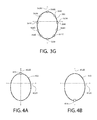
- FIGURE 3G is a diagram illustrating a necklace apparatus that comprises at least three speakers according to at least one example embodiment.
- the example of FIGURE 3G depicts a necklace apparatus comprising circumferential housing 360 in relation to frontal plane 362A and sagittal plane 362B.
- frontal plane 362A corresponds with frontal plane 204 of FIGURE 2
- sagittal plane 362B corresponds with sagittal plane 206 of FIGURE 2 .
- frontal plane 362A and sagittal plane 362B of the necklace apparatus depicted in the example of FIGURE 3G corresponds with frontal plane 204 and sagittal plane 206 of wearer 200 in the example of FIGURE 2 .
- the necklace apparatus comprises speakers 364A, 364B, 364C, 364D, 364E, 364F, 364G, 364H, 364I, and 364J, which are each coupled to circumferential housing 360 at a position along the circumferential housing that is different from a position along the circumferential housing of any other speaker of the depicted speakers.
- speakers 364A-364J may be identified as a rendering speaker and utilized in rendering of spatial audio information such that a wearer of the depicted necklace apparatus perceives the spatial audio information in accordance with the at least one spatial audio property.
- speaker 364A may be identified as a rendering speaker associated with rendering of spatial audio information that comprises at least one audio signal that has a rearward spatial audio property, a leftward spatial audio property, a rightward spatial audio property, an upward spatial audio property, and/or the like.
- speaker 364G may be identified as a rendering speaker associated with rendering of spatial audio information that comprises at least one audio signal that has a rightward spatial audio property, a frontward spatial audio property, an upward spatial audio property, and/or the like.
- FIGURES 4A-4B are diagrams illustrating a necklace apparatus that comprises at least one orientation reference point according to at least one example embodiment. The examples of FIGURES 4A-4B are merely examples and do not limit the scope of the claims.
- necklace apparatus design and/or configuration may vary, number of orientation reference points may vary, positions, designs, configurations, and/or arrangement of orientation reference points may vary, and/or the like.
- the necklace apparatus may move about the wearer's neck, may rotate with respect to the wearer's neck, and/or the like, such that an orientation of the necklace apparatus may change from an orientation to a different orientation.
- the necklace apparatus may rotate about the longitudinal axis of the wearer or, in other words, may rotate around the neck of the wearer.
- the portion of the circumferential housing that was previously the leftward portion of the circumferential housing of the necklace apparatus may rotate such that it corresponds with the portion of the wearer's neck that is to the right of the sagittal plane of the wearer.
- spatial audio information intended to be rendered leftward by way of a rendering speaker coupled to the previously leftward portion of the circumferential housing may instead by rendered rightward by way of the rendering speaker, which is now positioned rightward of the sagittal plane of the wearer.
- a necklace apparatus may be configured such that the necklace apparatus has an intended orientation.
- a necklace apparatus may be configured such that a clasp of the necklace apparatus is positioned at the rear-most position of a wearer's neck, at the highest position on the wearer's neck relative, and/or the like.
- a necklace apparatus may be configured such that a decorative element of the necklace apparatus is positioned at the front-most position of a wearer's neck, at the lowest point the necklace apparatus may reach on the wearer's upper check when worn around the wearer's neck, and/or the like.
- the necklace apparatus may have an intended orientation, a predetermined orientation relative to the clasp and/or the decorative element, and/or the like.
- a necklace apparatus comprises at least one orientation reference point coupled to the circumferential housing.
- the orientation reference point may, for example, indicate an orientation of the necklace apparatus.
- the orientation of the necklace apparatus may be a predetermined orientation of the necklace apparatus that is based, at least in part, on the orientation reference point.
- an orientation reference point is a coupling.
- the coupling may be configured to be oriented along a rearward portion of a sagittal plane of the wearer such that the coupling defines a rearward portion of a sagittal plane of the necklace apparatus.
- the orientation of the necklace apparatus is a predetermined orientation
- the identification of the at least one rendering speaker is based, at least in part, on the predetermined orientation.
- the predetermined orientation may be based, at least in part, on the coupling that indicates a predetermined orientation of the necklace apparatus.
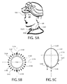
- FIGURE 4A is a diagram illustrating a necklace apparatus that comprises at least one orientation reference point according to at least one example embodiment.
- FIGURE 4A depicts a necklace apparatus comprising circumferential housing 400 in relation to frontal plane 402A and sagittal plane 402B.
- frontal plane 402A corresponds with frontal plane 204 of FIGURE 2
- sagittal plane 402B corresponds with sagittal plane 206 of FIGURE 2 .
- frontal plane 402A and sagittal plane 402B of the necklace apparatus depicted in the example of FIGURE 4A corresponds with frontal plane 204 and sagittal plane 206 of wearer 200 in the example of FIGURE 2 .
- the necklace apparatus depicted in FIGURE 4A comprises orientation reference point 404 coupled to circumferential housing 400 at a position that corresponds with the rearward portion of circumferential housing 400, and at the intersection of circumferential housing 400 and sagittal plane 402B.
- orientation reference point 404 is a coupling.
- the necklace apparatus may have a predetermined orientation associated with the necklace apparatus being worn by a wearer such that orientation reference point 404 rests on the rear-most portion of the wearer's neck.
- the circumferential housing of the necklace apparatus may comprise a leftward portion of the circumferential housing, a rightward portion of the circumferential housing, a frontward portion of the circumferential housing, a rearward portion of the circumferential housing, and/or the like, that are based, at least in part, on the predetermined orientation of the necklace apparatus and the coupling.
- an orientation reference point is a pendant.
- the pendant may be any decorative element, screen, housing, and/or the like, that is intended to be positioned at forward center of the wearer's neck, chest, and/or the like.
- the pendant may be configured to be oriented along a frontward portion of a sagittal plane of the wearer such that the pendant defines a frontward portion of a sagittal plane of the necklace apparatus.
- the orientation of the necklace apparatus is a predetermined orientation, and the identification of the at least one rendering speaker is based, at least in part, on the predetermined orientation.
- FIGURE 4B is a diagram illustrating a necklace apparatus that comprises at least one orientation reference point according to at least one example embodiment.
- the example of FIGURE 4B depicts a necklace apparatus comprising circumferential housing 410 in relation to frontal plane 412A and sagittal plane 412B.
- frontal plane 412A corresponds with frontal plane 204 of FIGURE 2
- sagittal plane 412B corresponds with sagittal plane 206 of FIGURE 2 .
- frontal plane 412A and sagittal plane 412B of the necklace apparatus depicted in the example of FIGURE 4B corresponds with frontal plane 204 and sagittal plane 206 of wearer 200 in the example of FIGURE 2 .
- the necklace apparatus depicted in FIGURE 4B comprises orientation reference point 414 coupled to circumferential housing 410 at a position that corresponds with the frontward portion of circumferential housing 410, and at the intersection of circumferential housing 410 and sagittal plane 412B.
- orientation reference point 414 is a pendant.
- the necklace apparatus may have a predetermined orientation associated with the necklace apparatus being worn by a wearer such that orientation reference point 414 rests on the front-most portion of the wearer's neck, at the center of the wearer's check, and/or the like.
- the circumferential housing of the necklace apparatus may comprise a leftward portion of the circumferential housing, a rightward portion of the circumferential housing, a frontward portion of the circumferential housing, a rearward portion of the circumferential housing, and/or the like, that are based, at least in part, on the predetermined orientation of the necklace apparatus and the pendant.
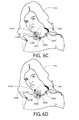
- FIGURES 5A-5C are diagrams illustrating a necklace apparatus that comprises at least three orientation sensors according to at least one example embodiment.
- the examples of FIGURES 5A-5C are merely examples and do not limit the scope of the claims.
- necklace apparatus design and/or configuration may vary, number of orientation sensors may vary, positions, designs, configurations, and/or arrangement of orientation sensors may vary, and/or the like.
- the necklace apparatus may move about the wearer's neck, may rotate with respect to the wearer's neck, and/or the like, such that an orientation of the necklace apparatus may change from an orientation to a different orientation.
- it may be desirable to configure the necklace apparatus such that the necklace apparatus may determine the orientation of the necklace apparatus for purposes associated with identification of at least one rendering speaker in accordance with at least one spatial rendering property.
- a necklace apparatus comprises at least three orientation sensors.
- the necklace apparatus may fail to comprise an orientation reference point.
- Each of the at least three orientation sensors may be an accelerometer, a gyroscope, a position sensor, a light sensor, a touch sensor, any other sensor configured to provide information indicative of orientation of the sensor, and/or the like.
- each orientation sensor of the at least three orientation sensors is separately coupled with the circumferential housing, such that each orientation sensor of the at least three orientation sensors is coupled with the circumferential housing at a position along the circumferential housing that is different from a position along the circumferential housing of any other orientation sensor of the at least three orientation sensors.
- the orientation sensors may be coupled to the circumferential housing at positions along the circumferential housing that correspond with positions along the circumferential housing of speakers coupled to the circumferential housing, a speaker and an orientation sensor may be integrally formed such that the speaker and orientation sensor are jointly coupled to the circumferential housing at a particular position along the circumferential housing, and/or the like.
- each orientation sensor of the at least three orientation sensors is coupled with the circumferential housing at a position along the circumferential housing that corresponds with a position along the circumferential housing of at least one speaker of the at least three speakers.
- the orientation sensors may be coupled to the circumferential housing at positions along the circumferential housing that fail to correspond with positions along the circumferential housing of speakers coupled to the circumferential housing, a speaker and an orientation sensor may fail to be integrally formed such that the speaker and orientation sensor are separately and distinctly coupled to the circumferential housing at different positions along the circumferential housing, and/or the like.
- at least one orientation sensor of the at least three orientation sensors is coupled with the circumferential housing at a position along the circumferential housing that fails to correspond with a position along the circumferential housing of any of the at least three speakers.
- the necklace apparatus is configured to receive orientation information from at least one of the at least three orientation sensors.
- the necklace apparatus may be configured to determine an orientation of the necklace apparatus based, at least in part, on the orientation information.
- the orientation of the necklace apparatus may be an orientation of the necklace apparatus relative to the wearer of the necklace apparatus, an orientation that is relative to the neck of the wearer of the necklace apparatus, an orientation that is relative to a predetermined orientation of the necklace apparatus, and/or the like.
- the orientation of the necklace apparatus is determined based, at least in part, on an orientation of at least one orientation sensor and an orientation of at least one other orientation sensor.
- the orientation of the necklace apparatus may be determined based, at least in part, on a direction of a gravitational force.
- the direction of the gravitational force may be a direction of the gravitational force with respect to the at least three orientation sensors, with respect to at least one orientation sensor of the at least three orientation sensors, and/or the like.
- a necklace apparatus receives orientation information from the at least three orientation sensors, and determines that the orientation of the necklace apparatus has changed from an orientation to a changed orientation.
- the changed orientation of the necklace apparatus may fail to correspond with the previous orientation of the necklace apparatus.
- a necklace apparatus may determine an orientation of the necklace apparatus, and identify at least one rendering speaker based, at least in part, on the orientation of the necklace apparatus.
- the necklace apparatus may subsequently cause the rendering speaker to render an audio signal based, at least in part, on the identification of the rendering speaker, the orientation of the necklace apparatus, the position of the rendering speaker corresponding with a direction associated with at least one spatial rendering property of the spatial audio information, and/or the like.
- the necklace apparatus may subsequently receive orientation information from at least one of the at least three orientation sensors, and determine that the orientation of the necklace apparatus has changed to a changed orientation.
- the necklace apparatus may identify at least one different rendering speaker of the at least three speakers based, at least in part, on the changed orientation of the necklace apparatus, and cause the at least one different rendering speaker to render the audio signal based, at least in part, on the identification of the at least one different rendering speaker, on the changed orientation of the necklace apparatus, on the position of the different rendering speaker corresponding with a direction associated with at least one spatial rendering property of the spatial audio information, and/or the like.
- FIGURE 5A is a diagram illustrating a necklace apparatus that comprises at least three orientation sensors according to at least one example embodiment.
- the example of FIGURE 5A depicts wearer 508 wearing a necklace apparatus that comprises circumferential housing 500 and orientation sensors 502A, 502B, and 502C.
- orientation sensors 502A, 502B, and 502C are coupled to circumferential housing 500 at various positions along circumferential housing 500.
- orientation sensors 502A, 502B, and 502C differ in orientation as each of orientation sensors 502A, 502B, and 502C are coupled to circumferential housing 500 at different positions along circumferential housing 500 and, thus, rest at different orientations against wearer 508's neck and chest.
- FIGURE 5B is a diagram illustrating an orientation sensor according to at least one example embodiment.
- the example of FIGURE 5B depicts orientation sensor 510 relative to circumferential housing axis 512A and gravitational force axis 512B.
- orientation sensor 510 may be coupled to a circumferential housing such that the circumferential housing is threaded through orientation sensor 510, such that the circumferential housing corresponds with circumferential housing axis 512A, and/or the like.
- gravitational force axis 512B is an axis associated with gravitational force, and is perpendicular to circumferential housing axis 512A.
- an orientation of an orientation sensor may be based, at least in part, on a direction of a gravitational force relative to a circumferential housing axis of the orientation sensor.
- a gravitational force acting straight down as illustrated by gravitational force indication 514A, may indicate that the orientation sensor is an orientation such that the circumferential housing axis is horizontal and right side up.
- Such a direction of gravitational force may indicate that the orientation sensor is positioned at the front-most position along the circumferential housing, at the front most position of the wearer's neck, and/or the like.
- a gravitational force acting leftward may indicate that the orientation sensor is orientation such that the circumferential housing axis is tilted from horizontal.
- a direction of gravitational force may indicate that the orientation sensor is positioned along a leftward portion of the circumferential housing of the necklace apparatus.
- a gravitational force acting rightward as illustrated by force indications 514D and 516D, may indicate that the orientation sensor is orientation such that the circumferential housing axis is tilted from horizontal.
- Such a direction of gravitational force may indicate that the orientation sensor is positioned along a rightward portion of the circumferential housing of the necklace apparatus.
- a gravitational force acting straight up may indicate that the orientation sensor is orientation such that the circumferential housing axis is horizontal and upside down.
- Such a direction of gravitational force may indicate that the orientation sensor is positioned at the rear-most position along the circumferential housing, at the back of the wearer's neck, and/or the like.
- an orientation may be rotatably coupled to a circumferential housing of a necklace apparatus.
- the orientation sensor may maintain a particular orientation with respect to the circumferential housing, may have a predetermined bottom, and/or the like.
- the upper portion of FIGURE 5B may correspond with the lower portion of FIGURE 5B .
- a gravitational force acting downward may indicate that the orientation sensor is positioned at the front-most position along the circumferential housing, at the front most position of the wearer's neck, and/or the like, or at the rear-most position along the circumferential housing, at the back of the wearer's neck, and/or the like.
- FIGURE 5C is a diagram illustrating a necklace apparatus that comprises at least three orientation sensors according to at least one example embodiment.
- the example of FIGURE 5C depicts a necklace apparatus comprising circumferential housing 520 in relation to frontal plane 522A and sagittal plane 522B.
- frontal plane 522A corresponds with frontal plane 204 of FIGURE 2
- sagittal plane 522B corresponds with sagittal plane 206 of FIGURE 2 .
- frontal plane 522A and sagittal plane 522B of the necklace apparatus depicted in the example of FIGURE 5C corresponds with frontal plane 204 and sagittal plane 206 of wearer 200 in the example of FIGURE 2 .
- the necklace apparatus depicted in FIGURE 5C comprises orientation sensors 524A, 524B, and 524C, each of which are coupled to circumferential housing 520 at different positions along circumferential housing 520.
- orientation sensor 524B is coupled to circumferential housing 520 at a position that corresponds with the frontward portion of circumferential housing 520, and at the intersection of circumferential housing 520 and sagittal plane 522B.
- the gravitational force experienced by orientation sensor 524B is perpendicular to the gravitational force axis, similar as described regarding orientation sensor 510 of FIGURE 5B .
- orientation sensor 524B may correspond with orientation sensor 510 experiencing a gravitational force indicated by gravitational force indication 514A, may correspond with orientation sensor 502B of FIGURE 5A , and/or the like.
- orientation sensor 524B Based, at least in part, on the direction of the gravitational force experienced by orientation sensor 524B, it may be determined that orientation sensor 524B is positioned along circumferential housing 520 at a position that corresponds with the intersection of circumferential housing 520 and sagittal plane 522B.
- orientation sensor 524A is coupled to circumferential housing 520 at a position that corresponds with the leftward portion of circumferential housing 520, and between frontal plane 522A and sagittal plane 522B.
- the gravitational force experienced by orientation sensor 524A is angled to the left from the gravitational force axis of sensor 524A, similar as described regarding orientation sensor 510 of FIGURE 5B .
- orientation sensor 524A may correspond with orientation sensor 510 experiencing a gravitational force indicated by gravitational force indication 514C, may correspond with orientation sensor 502A of FIGURE 5A , and/or the like.
- orientation sensor 524A Based, at least in part, on the direction of the gravitational force experienced by orientation sensor 524A, it may be determined that orientation sensor 524A is positioned along circumferential housing 520 at a position that corresponds with the leftward portion of circumferential housing 520, at a position between frontal plane 522A and sagittal plane 522B.
- orientation sensor 524C is coupled to circumferential housing 520 at a position that corresponds with the rightward portion of circumferential housing 520, and between frontal plane 522A and sagittal plane 522B.
- the gravitational force experienced by orientation sensor 524C is angled to the right from the gravitational force axis of sensor 524C, similar as described regarding orientation sensor 510 of FIGURE 5B .
- orientation sensor 524C may correspond with orientation sensor 510 experiencing a gravitational force indicated by gravitational force indication 514D, may correspond with orientation sensor 502C of FIGURE 5A , and/or the like.
- orientation sensor 524C Based, at least in part, on the direction of the gravitational force experienced by orientation sensor 524C, it may be determined that orientation sensor 524C is positioned along circumferential housing 520 at a position that corresponds with the rightward portion of circumferential housing 520, at a position between frontal plane 522A and sagittal plane 522B.
- orientation sensor 524C is closer to parallel with the circumferential housing axis of orientation sensor 524C than the gravitational force acting upon orientation sensor 524A, depicted as the downward arrow originating at orientation sensor 524A,.
- orientation sensor 524C is coupled to circumferential housing 520 at a position that is closer to the intersection of circumferential housing 520 and frontal plane 522A than orientation sensor 524A.
- the necklace apparatus may determine an orientation of the necklace apparatus based, at least in part, on orientation sensors 524A, 524B, and 524C.
- FIGURES 6A-6D are diagrams illustrating rendering of an audio signal by a rendering speaker according to at least one example embodiment.
- the examples of FIGURES 6A-6D are merely examples and do not limit the scope of the claims.
- necklace apparatus design and/or configuration may vary
- number of orientation sensors may vary
- positions, designs, configurations, and/or arrangement of orientation sensors may vary
- number of speakers may vary
- positions, designs, configurations, and/or arrangement of speakers may vary
- number of rendering speakers may vary, and/or the like.
- FIGURE 6A is a diagram illustrating rendering of an audio signal by a rendering speaker according to at least one example embodiment.
- the example of FIGURE 6A depicts wearer 608 wearing a necklace apparatus that comprises circumferential housing 600, to which speakers 604A, 604B, and 604C, and orientation sensors 606A, 606B, and 606C are coupled.
- the necklace apparatus may determine an orientation of the necklace apparatus based, at least in part, on orientation sensors 606A, 606B, and 606C.
- the necklace apparatus identifies speaker 604A, then speaker 604B, and, finally, speaker 604C as rendering speakers, and causes speaker 604A, then speaker 604B, and, finally, speaker 604C to render at least a portion of the audio signal of the spatial audio information.
- Such a progression across speakers 604A, 604B, and 604C may be based, at least in part, on a plurality of spatial audio properties associated with the spatial audio information.
- the necklace apparatus may be slightly rotated about wearer 608's neck. In such an example, the necklace apparatus may determine one or more changed orientations of the necklace apparatus, identify one or more different rendering speaker based, at least in part, on the changed orientation of the necklace apparatus, and cause the different rendering speaker to render the spatial audio information.
- FIGURE 7 is a flow diagram illustrating activities associated with causing a rendering speaker to render an audio signal according to at least one example embodiment.
- An apparatus for example electronic apparatus 10 of FIGURE 1 , or a portion thereof, may utilize the set of operations.
- the apparatus may comprise means, including, for example processor 11 of FIGURE 1 , for performance of such operations.
- an apparatus, for example electronic apparatus 10 of FIGURE 1 is transformed by having memory, for example memory 12 of FIGURE 1 , comprising computer code configured to, working with a processor, for example processor 11 of FIGURE 1 , cause the apparatus to perform set of operations of FIGURE 7 .
- the necklace apparatus receives spatial audio information that comprises at least one audio signal that has at least one spatial audio property.
- the receipt, the necklace apparatus, the spatial audio information, the audio signal, and the spatial audio property may be similar as described regarding FIGURES 3A-3G and FIGURES 6A-6D .
- the necklace apparatus identifies at least one rendering speaker of at least three speakers.
- the at least three speakers are separately coupled with a circumferential housing, such that each speaker of the at least three speakers is coupled with the circumferential housing at a position along the circumferential housing that is different from a position along the circumferential housing of any other speaker of the at least three speakers.
- the rendering speaker is identified such that a position along the circumferential housing of the rendering speaker corresponds with the spatial audio property. The identification, the rendering speaker, the speakers, the circumferential housing, and the position along the circumferential housing may be similar as described regarding FIGURES 3A-3G and FIGURES 6A-6D .
- the necklace apparatus causes the rendering speaker to render the audio signal based, at least in part, on the identification of the rendering speaker.
- the causation and the rendering may be similar as described regarding FIGURES 3A-3G and FIGURES 6A-6D .
- FIGURE 8 is a flow diagram illustrating activities associated with causing a rendering speaker to render an audio signal according to at least one example embodiment.
- An apparatus for example electronic apparatus 10 of FIGURE 1 , or a portion thereof, may utilize the set of operations.
- the apparatus may comprise means, including, for example processor 11 of FIGURE 1 , for performance of such operations.
- an apparatus, for example electronic apparatus 10 of FIGURE 1 is transformed by having memory, for example memory 12 of FIGURE 1 , comprising computer code configured to, working with a processor, for example processor 11 of FIGURE 1 , cause the apparatus to perform set of operations of FIGURE 8 .
- a rendering speaker may be desirable to identify a rendering speaker to render an audio signal based, at least in part, on a position along a circumferential housing of the rendering speaker corresponding with a spatial audio property.
- the necklace apparatus receives spatial audio information that comprises at least one audio signal that has at least a first spatial audio property, a second spatial audio property, and a third spatial audio property.
- the receipt, the necklace apparatus, the spatial audio information, the audio signal, the first spatial audio property, the second spatial audio property, and the third spatial audio property may be similar as described regarding FIGURES 3A-3G and FIGURES 6A-6D .
- the necklace apparatus identifies at least a first rendering speaker of at least three speakers.
- the at least three speakers are separately coupled with a circumferential housing, such that each speaker of the at least three speakers is coupled with the circumferential housing at a position along the circumferential housing that is different from a position along the circumferential housing of any other speaker of the at least three speakers.
- the first rendering speaker is identified such that a position along the circumferential housing of the first rendering speaker corresponds with the first spatial audio property. The identification, the first rendering speaker, the speakers, the circumferential housing, and the position along the circumferential housing may be similar as described regarding FIGURES 3A-3G and FIGURES 6A-6D .
- the necklace apparatus causes the first rendering speaker to render the audio signal based, at least in part, on the identification of the first rendering speaker.
- the causation and the rendering may be similar as described regarding FIGURES 3A-3G and FIGURES 6A-6D .
- the necklace apparatus identifies at least a second rendering speaker of the at least three speakers such that a position along the circumferential housing of the second rendering speaker corresponds with the second spatial audio property.
- the identification, the second rendering speaker, and the position along the circumferential housing may be similar as described regarding FIGURES 3A-3G and FIGURES 6A-6D .
- the necklace apparatus causes the second rendering speaker to render the audio signal based, at least in part, on the identification of the second rendering speaker.
- the causation and the rendering may be similar as described regarding FIGURES 3A-3G and FIGURES 6A-6D .
- the necklace apparatus identifies at least a third rendering speaker of the at least three speakers such that a position along the circumferential housing of the third rendering speaker corresponds with the third spatial audio property.
- the identification, the third rendering speaker, and the position along the circumferential housing may be similar as described regarding FIGURES 3A-3G and FIGURES 6A-6D .
- the necklace apparatus causes the third rendering speaker to render the audio signal based, at least in part, on the identification of the third rendering speaker.
- the causation and the rendering may be similar as described regarding FIGURES 3A-3G and FIGURES 6A-6D .
- FIGURE 9 is a flow diagram illustrating activities associated with causing a rendering speaker to render an audio signal according to at least one example embodiment.
- An apparatus for example electronic apparatus 10 of FIGURE 1 , or a portion thereof, may utilize the set of operations.
- the apparatus may comprise means, including, for example processor 11 of FIGURE 1 , for performance of such operations.
- an apparatus, for example electronic apparatus 10 of FIGURE 1 is transformed by having memory, for example memory 12 of FIGURE 1 , comprising computer code configured to, working with a processor, for example processor 11 of FIGURE 1 , cause the apparatus to perform set of operations of FIGURE 9 .
- a necklace apparatus such that the necklace apparatus identifies at least one rendering speaker to render an audio signal based, at least in part, on an orientation of the necklace apparatus.
- the necklace apparatus receives spatial audio information that comprises at least one audio signal that has at least one spatial audio property.
- the receipt, the necklace apparatus, the spatial audio information, the audio signal, and the spatial audio property may be similar as described regarding FIGURES 3A-3G and FIGURES 6A-6D .
- the necklace apparatus determines an orientation of the necklace apparatus.
- the determination and the orientation of the necklace apparatus may be similar as described regarding FIGURES 4A-4B and FIGURES 5A-5C .
- the necklace apparatus identifies at least one rendering speaker of at least three speakers.
- the at least three speakers are separately coupled with a circumferential housing, such that each speaker of the at least three speakers is coupled with the circumferential housing at a position along the circumferential housing that is different from a position along the circumferential housing of any other speaker of the at least three speakers.
- the rendering speaker is identified such that a position along the circumferential housing of the rendering speaker corresponds with the spatial audio property.
- the identification of the at least one rendering speaker is based on the orientation of the necklace apparatus.
- the identification, the rendering speaker, the speakers, the circumferential housing, and the position along the circumferential housing may be similar as described regarding FIGURES 3A-3G , FIGURES 4A-4B , FIGURES 5A-5C , and FIGURES 6A-6D .
- the necklace apparatus causes the rendering speaker to render the audio signal based, at least in part, on the identification of the rendering speaker.
- the causation and the rendering may be similar as described regarding FIGURES 3A-3G and FIGURES 6A-6D .
- FIGURE 10 is a flow diagram illustrating activities associated with causing a rendering speaker to render an audio signal according to at least one example embodiment.
- An apparatus, for example electronic apparatus 10 of FIGURE 1 , or a portion thereof, may utilize the set of operations.
- the apparatus may comprise means, including, for example processor 11 of FIGURE 1 , for performance of such operations.
- an apparatus, for example electronic apparatus 10 of FIGURE 1 is transformed by having memory, for example memory 12 of FIGURE 1 , comprising computer code configured to, working with a processor, for example processor 11 of FIGURE 1 , cause the apparatus to perform set of operations of FIGURE 10 .
- the orientation of the necklace apparatus may change to a changed orientation of the necklace apparatus.
- the necklace apparatus receives spatial audio information that comprises at least one audio signal that has at least one spatial audio property.
- the receipt, the necklace apparatus, the spatial audio information, the audio signal, and the spatial audio property may be similar as described regarding FIGURES 3A-3G and FIGURES 6A-6D .
- the necklace apparatus determines an orientation of the necklace apparatus.
- the determination and the orientation of the necklace apparatus may be similar as described regarding FIGURES 4A-4B and FIGURES 5A-5C .
- the necklace apparatus identifies at least one rendering speaker of at least three speakers.
- the at least three speakers are separately coupled with a circumferential housing, such that each speaker of the at least three speakers is coupled with the circumferential housing at a position along the circumferential housing that is different from a position along the circumferential housing of any other speaker of the at least three speakers.
- the rendering speaker is identified such that a position along the circumferential housing of the rendering speaker corresponds with the spatial audio property.
- the identification of the at least one rendering speaker is based on the orientation of the necklace apparatus.
- the identification, the rendering speaker, the speakers, the circumferential housing, and the position along the circumferential housing may be similar as described regarding FIGURES 3A-3G , FIGURES 4A-4B , FIGURES 5A-5C , and FIGURES 6A-6D .
- the necklace apparatus causes the rendering speaker to render the audio signal based, at least in part, on the identification of the rendering speaker.
- the causation and the rendering may be similar as described regarding FIGURES 3A-3G and FIGURES 6A-6D .
- the necklace apparatus determines that the orientation of the necklace apparatus has changed to a changed orientation of the necklace apparatus.
- the determination and the changed orientation of the necklace apparatus may be similar as described regarding FIGURES 3A-3G , FIGURES 4A-4B , FIGURES 5A-5C , and FIGURES 6A-6D .
- the necklace apparatus identifies at least one different rendering speaker of the at least three speakers based, at least in part, on the changed orientation of the necklace apparatus.
- the identification and the different rendering speaker may be similar as described regarding FIGURES 3A-3G , FIGURES 4A-4B , FIGURES 5A-5C , and FIGURES 6A-6D .
- Embodiments of the invention may be implemented in software, hardware, application logic or a combination of software, hardware, and application logic.
- the software, application logic, and/or hardware may reside on the apparatus, a separate device, or a plurality of separate devices.
- part of the software, application logic, and/or hardware may reside on the apparatus, part of the software, application logic and/or hardware may reside on a separate device, and part of the software, application logic and/or hardware may reside on a plurality of separate devices.
- the application logic, software or an instruction set is maintained on any one of various conventional computer-readable media.
- block 808 and block 810 of FIGURE 8 may be performed after block 814 of FIGURE 8 .
- block 904 of FIGURE 9 may be performed before block 902 of FIGURE 9 .
- one or more of the above-described functions may be optional or may be combined.
- block 812 and block 814 of FIGURE 8 may be optional and/or combined with block 808 and block 810 of FIGURE 8 .
Landscapes
- Physics & Mathematics (AREA)
- Engineering & Computer Science (AREA)
- Acoustics & Sound (AREA)
- Signal Processing (AREA)
- Details Of Audible-Bandwidth Transducers (AREA)
Abstract
Description
- The present application relates generally to a necklace apparatus.
- As electronic apparatuses become increasingly robust, there is a growing need for intuitive interactions with electronic apparatuses, information delivery methods, and/or the like. As such, it may be desirable to configure an electronic apparatus such that a user of the electronic apparatus may interact with the electronic apparatus and perceive information associated with the electronic apparatus in an easy and intuitive manner.
- Various aspects of examples of the invention are set out in the claims.
- One or more embodiments may provide an apparatus, a computer readable medium, a non-transitory computer readable medium, a computer program product, and a method for receiving, at a necklace apparatus, spatial audio information that comprises at least one audio signal that has at least one spatial audio property, identifying at least one rendering speaker of at least three speakers, the at least three speakers being separately coupled with a circumferential housing, such that each speaker of the at least three speakers is coupled with the circumferential housing at a position along the circumferential housing that is different from a position along the circumferential housing of any other speaker of the at least three speakers, the rendering speaker being identified such that a position along the circumferential housing of the rendering speaker corresponds with the spatial audio property, and causing the rendering speaker to render the audio signal based, at least in part, on the identification of the rendering speaker.
- One or more embodiments may provide an apparatus, a computer readable medium, a computer program product, and a non-transitory computer readable medium having means for receiving, at a necklace apparatus, spatial audio information that comprises at least one audio signal that has at least one spatial audio property, means for identifying at least one rendering speaker of at least three speakers, the at least three speakers being separately coupled with a circumferential housing, such that each speaker of the at least three speakers is coupled with the circumferential housing at a position along the circumferential housing that is different from a position along the circumferential housing of any other speaker of the at least three speakers, the rendering speaker being identified such that a position along the circumferential housing of the rendering speaker corresponds with the spatial audio property, and means for causing the rendering speaker to render the audio signal based, at least in part, on the identification of the rendering speaker.
- An apparatus comprising at least one processor and at least one memory, the memory comprising machine-readable instructions, that when executed cause the apparatus to perform receiving, at a necklace apparatus, spatial audio information that comprises at least one audio signal that has at least one spatial audio property, identifying at least one rendering speaker of at least three speakers, the at least three speakers being separately coupled with a circumferential housing, such that each speaker of the at least three speakers is coupled with the circumferential housing at a position along the circumferential housing that is different from a position along the circumferential housing of any other speaker of the at least three speakers, the rendering speaker being identified such that a position along the circumferential housing of the rendering speaker corresponds with the spatial audio property, and causing the rendering speaker to render the audio signal based, at least in part, on the identification of the rendering speaker.
- For a more complete understanding of embodiments of the invention, reference is now made to the following descriptions taken in connection with the accompanying drawings in which:
-
FIGURE 1 is a block diagram showing an apparatus according to at least one example embodiment; -
FIGURE 2 is a diagram illustrating anatomical terms of location, orientation, and/or the like, with respect to a wearer; -
FIGURES 3A-3G are diagrams illustrating a necklace apparatus that comprises at least three speakers according to at least one example embodiment; -
FIGURES 4A-4B are diagrams illustrating a necklace apparatus that comprises at least one orientation reference point according to at least one example embodiment; -
FIGURES 5A-5C are diagrams illustrating a necklace apparatus that comprises at least three orientation sensors according to at least one example embodiment; -
FIGURES 6A-6D are diagrams illustrating rendering of an audio signal by a rendering speaker according to at least one example embodiment; -
FIGURE 7 is a flow diagram illustrating activities associated with causing a rendering speaker to render an audio signal according to at least one example embodiment; -
FIGURE 8 is a flow diagram illustrating activities associated with causing a rendering speaker to render an audio signal according to at least one example embodiment; -
FIGURE 9 is a flow diagram illustrating activities associated with causing a rendering speaker to render an audio signal according to at least one example embodiment; and -
FIGURE 10 is a flow diagram illustrating activities associated with causing a rendering speaker to render an audio signal according to at least one example embodiment. - An embodiment of the invention and its potential advantages are understood by referring to
FIGURES 1 through 10 of the drawings.
Some embodiments will now be described more fully hereinafter with reference to the accompanying drawings, in which some, but not all, embodiments are shown. Various embodiments of the invention may be embodied in many different forms and should not be construed as limited to the embodiments set forth herein; rather, these embodiments are provided so that this disclosure will satisfy applicable legal requirements. Like reference numerals refer to like elements throughout. As used herein, the terms "data," "content," "information," and similar terms may be used interchangeably to refer to data capable of being transmitted, received and/or stored in accordance with embodiments of the present invention. Thus, use of any such terms should not be taken to limit the spirit and scope of embodiments of the present invention. - Additionally, as used herein, the term 'circuitry' refers to (a) hardware-only circuit implementations (e.g., implementations in analog circuitry and/or digital circuitry); (b) combinations of circuits and computer program product(s) comprising software and/or firmware instructions stored on one or more computer readable memories that work together to cause an apparatus to perform one or more functions described herein; and (c) circuits, such as, for example, a microprocessor(s) or a portion of a microprocessor(s), that require software or firmware for operation even if the software or firmware is not physically present. This definition of 'circuitry' applies to all uses of this term herein, including in any claims. As a further example, as used herein, the term 'circuitry' also includes an implementation comprising one or more processors and/or portion(s) thereof and accompanying software and/or firmware. As another example, the term 'circuitry' as used herein also includes, for example, a baseband integrated circuit or applications processor integrated circuit for a mobile phone or a similar integrated circuit in a server, a cellular network apparatus, other network apparatus, and/or other computing apparatus.
- As defined herein, a "non-transitory computer-readable medium," which refers to a physical medium (e.g., volatile or non-volatile memory device), can be differentiated from a "transitory computer-readable medium," which refers to an electromagnetic signal.
-
FIGURE 1 is a block diagram showing an apparatus, such as anelectronic apparatus 10, according to at least one example embodiment. It should be understood, however, that an electronic apparatus as illustrated and hereinafter described is merely illustrative of an electronic apparatus that could benefit from embodiments of the invention and, therefore, should not be taken to limit the scope of the invention. Whileelectronic apparatus 10 is illustrated and will be hereinafter described for purposes of example, other types of electronic apparatuses may readily employ embodiments of the invention.Electronic apparatus 10 may be a personal digital assistant (PDAs), a pager, a mobile computer, a desktop computer, a television, a gaming apparatus, a laptop computer, a tablet computer, a media player, a camera, a video recorder, a mobile phone, a wearable apparatus, a necklace apparatus, a beaded apparatus, a head worn apparatus, a neck worn apparatus, a global positioning system (GPS) apparatus, an automobile, a kiosk, an electronic table, and/or any other types of electronic systems. Moreover, the apparatus of at least one example embodiment need not be the entire electronic apparatus, but may be a component or group of components of the electronic apparatus in other example embodiments. For example, the apparatus may be an integrated circuit, a set of integrated circuits, and/or the like. - Furthermore, apparatuses may readily employ embodiments of the invention regardless of their intent to provide mobility. In this regard, even though embodiments of the invention may be described in conjunction with mobile applications, it should be understood that embodiments of the invention may be utilized in conjunction with a variety of other applications, both in the mobile communications industries and outside of the mobile communications industries. For example, the apparatus may be, at least part of, a non-carryable apparatus, such as a large screen television, an electronic table, a kiosk, an automobile, and/or the like.
- In at least one example embodiment,
electronic apparatus 10 comprisesprocessor 11 andmemory 12.Processor 11 may be any type of processor, controller, embedded controller, processor core, and/or the like. In at least one example embodiment,processor 11 utilizes computer program code to cause an apparatus to perform one or more actions.Memory 12 may comprise volatile memory, such as volatile Random Access Memory (RAM) including a cache area for the temporary storage of data and/or other memory, for example, non-volatile memory, which may be embedded and/or may be removable. The non-volatile memory may comprise an EEPROM, flash memory and/or the like.Memory 12 may store any of a number of pieces of information, and data. The information and data may be used by theelectronic apparatus 10 to implement one or more functions of theelectronic apparatus 10, such as the functions described herein. In at least one example embodiment,memory 12 includes computer program code such that the memory and the computer program code are configured to, working with the processor, cause the apparatus to perform one or more actions described herein. - The
electronic apparatus 10 may further comprise acommunication device 15. In at least one example embodiment,communication device 15 comprises an antenna, (or multiple antennae), a wired connector, and/or the like in operable communication with a transmitter and/or a receiver. In at least one example embodiment,processor 11 provides signals to a transmitter and/or receives signals from a receiver. The signals may comprise signaling information in accordance with a communications interface standard, user speech, received data, user generated data, and/or the like.Communication device 15 may operate with one or more air interface standards, communication protocols, modulation types, and access types. By way of illustration, theelectronic communication device 15 may operate in accordance with second-generation (2G) wireless communication protocols IS-136 (time division multiple access (TDMA)), Global System for Mobile communications (GSM), and IS-95 (code division multiple access (CDMA)), with third-generation (3G) wireless communication protocols, such as Universal Mobile Telecommunications System (UMTS), CDMA2000, wideband CDMA (WCDMA) and time division-synchronous CDMA (TD-SCDMA), and/or with fourth-generation (4G) wireless communication protocols, wireless networking protocols, such as 802.11, short-range wireless protocols, such as Bluetooth, and/or the like.Communication device 15 may operate in accordance with wireline protocols, such as Ethernet, digital subscriber line (DSL), asynchronous transfer mode (ATM), and/or the like.Processor 11 may comprise means, such as circuitry, for implementing audio, video, communication, navigation, logic functions, and/or the like, as well as for implementing embodiments of the invention including, for example, one or more of the functions described herein. For example,processor 11 may comprise means, such as a digital signal processor device, a microprocessor device, various analog to digital converters, digital to analog converters, processing circuitry and other support circuits, for performing various functions including, for example, one or more of the functions described herein. The apparatus may perform control and signal processing functions of theelectronic apparatus 10 among these devices according to their respective capabilities. Theprocessor 11 thus may comprise the functionality to encode and interleave message and data prior to modulation and transmission. The processor 1 may additionally comprise an internal voice coder, and may comprise an internal data modem. Further, theprocessor 11 may comprise functionality to operate one or more software programs, which may be stored in memory and which may, among other things, cause theprocessor 11 to implement at least one embodiment including, for example, one or more of the functions described herein. For example, theprocessor 11 may operate a connectivity program, such as a conventional internet browser. The connectivity program may allow theelectronic apparatus 10 to transmit and receive internet content, such as location-based content and/or other web page content, according to a Transmission Control Protocol (TCP), Internet Protocol (IP), User Datagram Protocol (UDP), Internet Message Access Protocol (IMAP), Post Office Protocol (POP), Simple Mail Transfer Protocol (SMTP), Wireless Application Protocol (WAP), Hypertext Transfer Protocol (HTTP), and/or the like, for example. - The
electronic apparatus 10 may comprise a user interface for providing output and/or receiving input. Theelectronic apparatus 10 may comprise anoutput device 14.Output device 14 may comprise an audio output device, such as a ringer, an earphone, a speaker, and/or the like.Output device 14 may comprise a tactile output device, such as a vibration transducer, an electronically deformable surface, an electronically deformable structure, and/or the like.Output device 14 may comprise a visual output device, such as a display, a light, and/or the like. In at least one example embodiment, the apparatus causes display of information, the causation of display may comprise displaying the information on a display comprised by the apparatus, sending the information to a separate apparatus that comprises a display, and/or the like. The electronic apparatus may comprise aninput device 13.Input device 13 may comprise a light sensor, a proximity sensor, a microphone, a touch sensor, a force sensor, a button, a keypad, a motion sensor, a magnetic field sensor, a camera, and/or the like. A touch sensor and a display may be characterized as a touch display. In an embodiment comprising a touch display, the touch display may be configured to receive input from a single point of contact, multiple points of contact, and/or the like. In such an embodiment, the touch display and/or the processor may determine input based, at least in part, on position, motion, speed, contact area, and/or the like. In at least one example embodiment, the apparatus receives an indication of an input. The apparatus may receive the indication from a sensor, a driver, a separate apparatus, and/or the like. The information indicative of the input may comprise information that conveys information indicative of the input, indicative of an aspect of the input indicative of occurrence of the input, and/or the like. Theelectronic apparatus 10 may include any of a variety of touch displays including those that are configured to enable touch recognition by any of resistive, capacitive, infrared, strain gauge, surface wave, optical imaging, dispersive signal technology, acoustic pulse recognition or other techniques, and to then provide signals indicative of the location and other parameters associated with the touch. Additionally, the touch display may be configured to receive an indication of an input in the form of a touch event which may be defined as an actual physical contact between a selection object (e.g., a finger, stylus, pen, pencil, or other pointing device) and the touch display. Alternatively, a touch event may be defined as bringing the selection object in proximity to the touch display, hovering over a displayed object or approaching an object within a predefined distance, even though physical contact is not made with the touch display. As such, a touch input may comprise any input that is detected by a touch display including touch events that involve actual physical contact and touch events that do not involve physical contact but that are otherwise detected by the touch display, such as a result of the proximity of the selection object to the touch display. A touch display may be capable of receiving information associated with force applied to the touch screen in relation to the touch input. For example, the touch screen may differentiate between a heavy press touch input and a light press touch input. In at least one example embodiment, a display may display two-dimensional information, three-dimensional information and/or the like. - In embodiments including a keypad, the keypad may comprise numeric (for example, 0-9) keys, symbol keys (for example, #, *), alphabetic keys, and/or the like for operating the
electronic apparatus 10. For example, the keypad may comprise a conventional QWERTY keypad arrangement. The keypad may also comprise various soft keys with associated functions. In addition, or alternatively, theelectronic apparatus 10 may comprise an interface device such as a joystick or other user input interface. -
Input device 13 may comprise a media capturing element. The media capturing element may be any means for capturing an image, video, and/or audio for storage, display or transmission. For example, in at least one example embodiment in which the media capturing element is a camera module, the camera module may comprise a digital camera which may form a digital image file from a captured image. As such, the camera module may comprise hardware, such as a lens or other optical component(s), and/or software necessary for creating a digital image file from a captured image. Alternatively, the camera module may comprise only the hardware for viewing an image, while a memory device of theelectronic apparatus 10 stores instructions for execution by theprocessor 11 in the form of software for creating a digital image file from a captured image. In at least one example embodiment, the camera module may further comprise a processing element such as a co-processor that assists theprocessor 11 in processing image data and an encoder and/or decoder for compressing and/or decompressing image data. The encoder and/or decoder may encode and/or decode according to a standard format, for example, a Joint Photographic Experts Group (JPEG) standard format. -
FIGURE 2 is a diagram illustrating anatomical terms of location, orientation, and/or the like, with respect towearer 200. It can be seen thatwearer 200 is depicted in an anatomic position. An anatomic position is a posture of a human body in which the body is standing with legs slightly apart with feet forward and palms facing forward. The body ofwearer 200 may be described in relation to three fundamental axes that are orthogonal to each other; the frontal axis, the longitudinal axis, and the sagittal axis.Frontal axis 201 is an imaginary line that extends from right to left through the center ofwearer 200.Longitudinal axis 202 is a line that extends from superior (upper) to inferior (lower) through the center ofwearer 200.Sagittal axis 203 is a line that extends from anterior to posterior through the center ofwearer 200.Frontal plane 204 is a plane that divideswearer 200 into anterior and posterior halves alongfrontal axis 201 andlongitudinal axis 202. It can be seen that, whenwearer 200 is in the anatomical position, the frontal plane divides the body and neck ofwearer 200 into front and back parts.Transverse plane 205 is a plane that divideswearer 200 into superior and inferior parts throughfrontal axis 201 andsagittal axis 203.Sagittal plane 206 is a plane that divideswearer 200 into left and right parts throughsagittal axis 203 andlongitudinal axis 202. It can be seen that, whenwearer 200 is in the anatomical position, the sagittal plane divides the body and neck ofwearer 200 into left and right parts. -
FIGURES 3A-3G are diagrams illustrating a necklace apparatus that comprises at least three speakers according to at least one example embodiment. The examples ofFIGURES 3A-3G are merely examples and do not limit the scope of the claims. For example, necklace apparatus design and/or configuration may vary, number of speakers may vary, positions and/or arrangement of speakers may vary, and/or the like. - In many circumstances, a user may desire to interact with an electronic apparatus throughout the user's day. For example, the user may desire to perceive indications associated with messages, notifications, emails, alerts, phone calls, and/or the like. In such an example, the user may desire to utilize the electronic apparatus in a matter that is easy and convenient for the user. For example, the user may desire to avoid holding the electronic apparatus in the user's hands, avoid storing the electronic apparatus in the user's pocket only to subsequently retrieve the electronic apparatus upon receipt of a notification, and/or the like. As such, in at least one example embodiment, an apparatus is a wearable apparatus. A wearable apparatus is an apparatus that is configured to be worn by a wearer. For example, a wearable apparatus may be a necklace apparatus, a bracelet apparatus, a ring apparatus, and/or the like. In this manner, the apparatus may be a head-worn apparatus, neck-worn apparatus, a wrist-worn apparatus, a finger-worn apparatus, and/or the like, such that the apparatus is configured to be worn by a wearer on the respective portion of the wearer's body. In at least one example embodiment, an apparatus is a necklace apparatus. For example, the necklace apparatus may be an apparatus that is configured to be worn on the neck of a wearer. The necklace apparatus may be a beaded necklace apparatus, a contiguous necklace apparatus, and/or the like.
- In order to facilitate wearing of the necklace apparatus by a user, it may be desirable to configure the necklace apparatus such that a user may easily wear the necklace apparatus, remove the necklace apparatus, and/or the like. In at least one example embodiment, a necklace apparatus comprises a circumferential housing. The circumferential housing may have a substantially uniform cross section across the entirety of the circumferential housing, a portion of the circumferential housing, and/or the like. In such an example embodiment, the circumferential housing is a contiguous structure configured to surround a neck of a wearer of the necklace apparatus. For example, the circumferential housing may comprise an end of the circumferential housing, an opposite end of the circumferential housing, and a coupling that is configured to connect the end to the opposite end. In such an example, the connection of the end to the opposite end by way of the coupling is such that the circumferential housing is a contiguous structure. In some circumstances, it may be desirable to configure the necklace apparatus such that the end and the opposite end of the circumferential housing are configured to remain coupled, to be non-user-separable, and/or the like. In at least one example embodiment, the coupling is a fixed coupling. For example, the coupling may be a riveted coupling, a glued coupling, an injection molded coupling, a stitched coupling, a welded coupling, a mechanical coupling, and/or the like. In other circumstances, it may be desirable to configure the necklace apparatus such that the end and the opposite end of the circumferential housing are configured to be separably coupled, to be user-separable, and/or the like. In at least one example embodiment, the coupling is a non-fixed coupling. For example, the coupling may be a clasp, a hook, a detachable coupling, a magnetic coupling, and/or the like. The coupling may be a distinct element of the circumferential housing. For example, the coupling may fail to be an integral element of the circumferential housing, separable from the circumferential housing, and/or the like.
-
FIGURE 3A is a diagram illustrating a necklace apparatus that comprises at least three speakers according to at least one example embodiment. The example ofFIGURE 3A depicts a necklace apparatus comprisingcircumferential housing 300 in relation tofrontal plane 302A andsagittal plane 302B. In the example ofFIGURE 3A ,frontal plane 302A corresponds withfrontal plane 204 ofFIGURE 2 andsagittal plane 302B corresponds withsagittal plane 206 ofFIGURE 2 . In this manner,frontal plane 302A andsagittal plane 302B of the necklace apparatus depicted in the example ofFIGURE 3A correspond withfrontal plane 204 andsagittal plane 206 ofwearer 200 in the example ofFIGURE 2 . - In some circumstances, it may be desirable to characterize one or more portions of a necklace apparatus. For example, a necklace apparatus may be designed to be worn by a wearer in a certain manner, configured to be worn around the neck of a wearer in a certain orientation, and/or the like. In at least one example embodiment, the circumferential housing comprises a leftward portion of the circumferential housing. In such an example embodiment, the leftward portion of the circumferential housing may be a portion of the circumferential housing that is left of a sagittal plane of the necklace apparatus. As can be seen in the example of
FIGURE 3A , the portion ofcircumferential housing 300 that is to the left ofsagittal plane 302B is the leftward portion ofcircumferential housing 300. In at least one example embodiment, the circumferential housing comprises a rightward portion of the circumferential housing. In such an example embodiment, the rightward portion of the circumferential housing may be a portion of the circumferential housing that is right of a sagittal plane of the necklace apparatus. As can be seen in the example ofFIGURE 3A , the portion ofcircumferential housing 300 that is to the right ofsagittal plane 302B is the rightward portion ofcircumferential housing 300. In at least one example embodiment, the circumferential housing comprises a frontward portion of the circumferential housing. In such an example embodiment, the frontward portion of the circumferential housing may be a portion of the circumferential housing that is forward of a frontal plane of the necklace apparatus. As can be seen in the example ofFIGURE 3A , as depicted, the portion ofcircumferential housing 300 that is belowfrontal plane 302A is the frontward portion ofcircumferential housing 300. In at least one example embodiment, the circumferential housing comprises a rearward portion of the circumferential housing. In such an example embodiment, the rearward portion of the circumferential housing may be a portion of the circumferential housing that is rearward of a frontal plane of the necklace apparatus. As can be seen in the example ofFIGURE 3A , as depicted, the portion ofcircumferential housing 300 that is abovefrontal plane 302A is the rearward portion ofcircumferential housing 300. In this manner, the necklace apparatus may be configured to be worn by a wearer such that the portions of the circumferential housing correspond with the anatomical coordinates discussed in the example ofFIGURE 2 . For example, the necklace apparatus may be configured such that the frontward portion of the circumferential housing is intended to be worn on a portion ofwearer 200's neck that is forward offrontal plane 204 ofFIGURE 2 . In another example, the necklace apparatus may be configured such that the leftward portion of the circumferential housing is intended to be worn on a portion ofwearer 200's neck that is to the left ofsagittal plane 206 ofFIGURE 2 . - As discussed previously, in many circumstances, a user may desire to perceive auditory indications associated with messages, alarms, alerts, notifications, and/or the like. Additionally, the user may desire to listen to music, sound effects associated with an interactive interface and/or game, an auditory component of a video, and/or the like. As such, it may be desirable to configure a necklace apparatus such that the necklace apparatus may render auditory information. In at least one example embodiment, a necklace apparatus comprises a speaker. The speaker may be an audio output transducer, a loud speaker, an electromechanical device which produces sound, and/or the like. In at least one example embodiment, a speaker is configured to render audio information. In such an example embodiment, audio information may comprise at least one audio signal that is configured to actuate the speaker in a manner that allows for user perception of the audio signal.
- As users have become increasingly reliant upon electronic apparatuses in everyday activities and duties, electronic apparatuses have become increasingly complex and robust. In many circumstances, users have come to expect electronic apparatuses that are configured to offer robust and immersive user experiences and user interactions, and electronic apparatuses that are configured to provide a myriad of information to the user. As such, it may be desirable to configure a necklace apparatus such that the necklace apparatus may convey information to the user by way of audio information. In at least one example embodiment, a necklace apparatus is configured to render spatial audio information. Spatial audio may, for example, be audio that is perceived to be projected from a certain location in physical space, audio that is perceived to emanate from a particular localized source and/or direction, and/or the like. In such an example embodiment, a wearer of a necklace apparatus may perceive an audio signal that is being rendered by the necklace apparatus to be rendered at a location that is to the left of the wearer, to the right of the wearer, forward of the wearer, above the wearer, behind the wearer, surrounding the wearer, and/or the like. In this manner, in addition to the information conveyed in the audio signal, the necklace apparatus may convey additional information to the wearer by way of one or more spatial properties of the audio signal.
- In order to facilitate rendering of spatial audio information, it may be desirable to configure a necklace apparatus such that the necklace apparatus comprises a plurality of speakers. In such an example, the speakers may be arranged such that the speakers may render such spatial audio information in a manner perceivable by a wearer of the necklace apparatus to be rendered at a location that is to the left of the wearer, to the right of the wearer, forward of the wearer, above the wearer, behind the wearer, surrounding the wearer, and/or the like. In at least one example embodiment, a necklace apparatus comprises at least three speakers separately coupled with the circumferential housing. In such an example embodiment, each speaker of the at least three speakers may be coupled with the circumferential housing at a position along the circumferential housing that is different from a position along the circumferential housing of any other speaker of the at least three speakers. In this manner, the at least three speakers may be coupled to the circumferential housing at three distinct positions along the circumferential housing.
- In order to facilitate wearer perception of an audio signal being rendered by a necklace apparatus, it may be desirable to configure the necklace apparatus such that the speakers comprised by the necklace apparatus are oriented in a manner that facilitates wearer perception of the audio signal rendered by the speakers. For example, as the necklace apparatus may be intended to be worn around the neck of a wearer, it may be desirable for the speakers of the necklace apparatus to be angled towards the ears of the wearer, outward from the wearer's neck, and/or the like. In at least one example embodiment, the at least three speakers are coupled to the circumferential housing such that each of the at least three speakers face an outward direction. In such an example embodiment, the outward direction may be relative to a position along a longitudinal axis of the necklace apparatus that is central to the necklace apparatus. In at least one example embodiment, the at least three speakers are coupled to the circumferential housing such that each of the at least three speakers face an upward direction. In such an example embodiment, the upward direction may be relative to a position along a longitudinal axis of the necklace apparatus that is central to the necklace apparatus.
- In many circumstances, the exact position at which the speakers are coupled to the circumferential housing may affect rendering of spatial audio information. For example, in order to render spatial audio information that is perceived as being rendered behind a wearer of a necklace apparatus, the necklace apparatus may comprise at least one speaker that is coupled to a rearward portion of the circumferential housing of the necklace apparatus. In another example, in order to render spatial audio information that is perceived as being rendered to the left a wearer of a necklace apparatus, the necklace apparatus may comprise at least one speaker that is coupled to a leftward portion of the circumferential housing of the necklace apparatus. In this manner, the arrangement of the at least three speakers along the circumferential housing may be influenced by one or more functionality requirements, design constraints, and/or the like. In at least one example embodiment, the at least three speakers are coupled to the circumferential housing such that a distance between adjacent speakers of the at least three speakers is substantially equal. In such an example embodiment, the distance between adjacent speakers may be a distance between adjacent speakers of the at least three speakers along the circumferential housing. The distance between adjacent speakers of the at least three speakers may be substantially equal along an entirety of the circumferential housing, substantially equal along a portion of the circumferential housing, and/or the like. The portion of the circumferential housing may be a portion of the circumferential housing that is less than an entirety of the circumferential housing, a frontward portion, a leftward portion of the circumferential housing, a rightward portion of the circumferential housing, a rearward portion of the circumferential housing, and/or the like. In at least one example embodiment, the leftward portion of the circumferential housing is symmetrical to a rightward portion of the circumferential housing. In such an example embodiment, the at least three speakers are coupled to the circumferential housing such that the leftward portion of the circumferential housing is symmetrical to a rightward portion of the circumferential housing. Similarly, in at least one example embodiment, the frontward portion of the circumferential housing is symmetrical to a rearward portion of the circumferential housing. In such an example embodiment, the at least three speakers are coupled to the circumferential housing such that the frontward portion of the circumferential housing is symmetrical to a rearward portion of the circumferential housing.
- As discussed previously, in many circumstances, it may be desirable to configure a necklace apparatus such that the necklace apparatus may render spatial audio information by way of at least three speakers that are coupled to the circumferential housing of the necklace apparatus. In at least one example embodiment, the at least three speakers are configured to render spatial audio information that comprises at least one audio signal that has at least one spatial audio property. In such an example embodiment, the spatial audio property may be a property that indicates a direction associated with rendering of the audio signal of the spatial audio information. The direction may be a cardinal direction, a relative direction such as above, below, left, right, forward, behind, and/or the like, a three-dimensional angular direction with respect to a wearer, and/or the like. In this manner, spatial audio information that is intended to be perceived as being rendered from a position to the left of the wearer may comprise at least one audio signal that has at least one spatial audio property that indicates a direction to the left of the wearer.
- As such, it may be desirable to couple the at least three speakers to the circumferential housing at positions that allow for and/or facilitate such rendering of spatial audio information in accordance with the at least one spatial audio property. In this manner, a position of a speaker along the circumferential housing may correspond with a spatial audio property of an audio signal intended to be rendered by the necklace apparatus. In at least one example embodiment, a location of at least one speaker of at least three speakers along the circumferential housing corresponds with the spatial audio property. In such an example embodiment, the at least one speaker of the at least three speakers may be identified as a rendering speaker based, at least in part, on the position of the at least one speaker of the at least three speakers along the circumferential housing corresponding with the spatial audio property. Correspondence between a speaker of the at least three speakers and the spatial audio property may be indicative of correspondence between the position of the at least one speaker of the at least three speakers and a direction indicated by the spatial audio property. For example, a spatial audio property may be a leftward spatial audio property, and the rendering speaker may be identified as a speaker that is coupled to a leftward portion of the circumferential housing. In such an example, the necklace apparatus may be configured to identify a rendering speaker that is coupled to the leftward portion of the circumferential housing based, at least in part, on the spatial audio property being the leftward spatial audio property and the rendering speaker being coupled to the leftward portion of the circumferential housing.
- In another example, a spatial audio property may be a rightward spatial audio property, and the rendering speaker may be identified as a speaker that is coupled to a rightward portion of the circumferential housing. In such an example, the necklace apparatus may be configured to identify a rendering speaker that is coupled to the rightward portion of the circumferential housing based, at least in part, on the spatial audio property being the rightward spatial audio property and the rendering speaker being coupled to the rightward portion of the circumferential housing.
- In another example, a spatial audio property may be a frontward spatial audio property, and the rendering speaker may be identified as a speaker that is coupled to a frontward portion of the circumferential housing. In such an example, the necklace apparatus may be configured to identify a rendering speaker that is coupled to the frontward portion of the circumferential housing based, at least in part, on the spatial audio property being the frontward spatial audio property and the rendering speaker being coupled to the frontward portion of the circumferential housing.
- In another example, a spatial audio property may be a rearward spatial audio property, and the rendering speaker may be identified as a speaker that is coupled to a rearward portion of the circumferential housing. In such an example, the necklace apparatus may be configured to identify a rendering speaker that is coupled to the rearward portion of the circumferential housing based, at least in part, on the spatial audio property being the rearward spatial audio property and the rendering speaker being coupled to the rearward portion of the circumferential housing.
- In this manner, to effect such rendering of spatial audio information, the necklace apparatus may receive spatial audio information that comprises at least one audio signal that has at least one spatial audio property. The spatial audio information may be received from a separate apparatus, from at least one memory, from a repository, from a database, and/or the like. For example, the spatial audio information may be received from a phone, a computer, a streaming platform, a radio transmitter, and/or the like. In at least one example embodiment, the spatial audio information is received by way of at least one communication channel. In such an example embodiment, the communication channel may be a wireless communication channel, a wired communication channel, a wireless local area network communication channel, a Bluetooth communication channel, a cellular communication channel, and/or the like. Subsequent to receipt of at least a portion of the spatial audio information, the necklace apparatus may identify at least one rendering speaker of at least three speakers. As discussed previously, the at least three speakers may be separately coupled with a circumferential housing such that each speaker of the at least three speakers is coupled with the circumferential housing at a position along the circumferential housing that is different from a position along the circumferential housing of any other speaker of the at least three speakers. In such an example, the rendering speaker may be identified such that a position along the circumferential housing of the rendering speaker corresponds with the spatial audio property. Subsequently, the necklace apparatus may cause the rendering speaker to render the audio signal. The causation of the rendering speaker to render the audio signal may be based, at least in part, on the identification of the rendering speaker. In such an example, the rendering of the audio signal may comprise actuation of the rendering speaker in accordance with the audio signal such that a wearer of the necklace apparatus may perceive auditory information. Causation of rendering of the audio signal may comprise sending of the audio signal to the rendering speaker, supplying power to the rendering speaker such that the rendering speaker may render the audio signal, and/or the like.
- The examples of
FIGURES 3A-3G are diagrams that depict various configurations of a necklace apparatus. For example,FIGURES 3A-3G depict necklace apparatuses that comprise various numbers of speakers coupled to the circumferential housing of the necklace apparatuses, speakers coupled to the circumferential housings at various positions and in carious arrangements, and/or the like. It should be understood thatFIGURES 3A-3G are merely examples and do not limit the scope of the claims. For example, any number of speakers may be coupled to the circumferential housing of a necklace apparatus, a speaker may be coupled at any position along the circumferential housing of a necklace apparatus, and/or the like. Although the examples ofFIGURES 3A-3G depict the speakers as a singular circle shape, the design and/or construction of the speakers may differ, the number of speakers at each position along the circumferential housing may differ, and/or the like. In the examples ofFIGURES 3A-3G , one or more of the depicted speakers may be identified as rendering speakers and utilized in rendering of spatial audio information such that a wearer of the depicted necklace apparatus perceives the spatial audio information in accordance with the at least one spatial audio property. - As discussed previously,
FIGURE 3A is a diagram illustrating a necklace apparatus that comprises at least three speakers according to at least one example embodiment. In the example ofFIGURE 3A , the necklace apparatus comprisesspeakers circumferential housing 300 at a position along the circumferential housing that is different from a position along the circumferential housing of any other speaker of the depicted speakers. - As can be seen in the example of
FIGURE 3A ,speaker 304A is coupled tocircumferential housing 300 at a position that corresponds with the leftward portion ofcircumferential housing 300, and at the intersection of the leftward portion ofcircumferential housing 300 andfrontal plane 302A. In this manner,speaker 304A may be identified as a rendering speaker associated with rendering of spatial audio information that comprises at least one audio signal that has a leftward spatial audio property. The identification ofspeaker 304A as the rendering speaker may be based, at least in part, on the correspondence of the leftward portion of the circumferential housing and the leftward direction of the spatial audio property. As can be seen in the example ofFIGURE 3A , speaker 304B is coupled tocircumferential housing 300 at a position that corresponds with the frontward portion ofcircumferential housing 300, and at the intersection of the frontward portion ofcircumferential housing 300 andsagittal plane 302B. In this manner, speaker 304B may be identified as a rendering speaker associated with rendering of spatial audio information that comprises at least one audio signal that has a frontward spatial audio property. The identification of speaker 304B as the rendering speaker may be based, at least in part, on the correspondence of the frontward portion of the circumferential housing and the frontward direction of the spatial audio property. As can be seen in the example ofFIGURE 3A ,speaker 304C is coupled tocircumferential housing 300 at a position that corresponds with the rightward portion ofcircumferential housing 300, and at the intersection of the rightward portion ofcircumferential housing 300 andfrontal plane 302A. In this manner,speaker 304C may be identified as a rendering speaker associated with rendering of spatial audio information that comprises at least one audio signal that has a rightward spatial audio property. The identification ofspeaker 304C as the rendering speaker may be based, at least in part, on the correspondence of the rightward portion of the circumferential housing and the rightward direction of the spatial audio property. -
FIGURE 3B is a diagram illustrating a necklace apparatus that comprises at least three speakers according to at least one example embodiment. The example ofFIGURE 3B depicts a necklace apparatus comprisingcircumferential housing 310 in relation tofrontal plane 312A andsagittal plane 312B. In the example ofFIGURE 3B ,frontal plane 312A corresponds withfrontal plane 204 ofFIGURE 2 andsagittal plane 312B corresponds withsagittal plane 206 ofFIGURE 2 . In this manner,frontal plane 312A andsagittal plane 312B of the necklace apparatus depicted in the example ofFIGURE 3B corresponds withfrontal plane 204 andsagittal plane 206 ofwearer 200 in the example ofFIGURE 2 . In the example ofFIGURE 3B , the necklace apparatus comprisesspeakers circumferential housing 310 at a position along the circumferential housing that is different from a position along the circumferential housing of any other speaker of the depicted speakers. - As can be seen in the example of
FIGURE 3B ,speaker 314A is coupled tocircumferential housing 310 at a position that corresponds with the leftward portion ofcircumferential housing 310, and at the intersection of the leftward portion ofcircumferential housing 310 andfrontal plane 312A. In this manner,speaker 314A may be identified as a rendering speaker associated with rendering of spatial audio information that comprises at least one audio signal that has a leftward spatial audio property, a frontward spatial audio property, a rearward spatial audio property, and/or the like. For example, the identification ofspeaker 314A as the rendering speaker may be based, at least in part, on the correspondence of the leftward portion of the circumferential housing and the leftward direction of the spatial audio property. As can be seen in the example ofFIGURE 3B ,speaker 314B is coupled tocircumferential housing 310 at a position that corresponds with the rearward portion ofcircumferential housing 310, and at the intersection of the rearward portion ofcircumferential housing 310 andsagittal plane 312B. In this manner,speaker 314B may be identified as a rendering speaker associated with rendering of spatial audio information that comprises at least one audio signal that has a rearward spatial audio property, a leftward spatial audio property, a rightward spatial audio property, an upwards spatial audio property, and/or the like. For example, the identification ofspeaker 314B as the rendering speaker may be based, at least in part, on the correspondence of the rearward portion of the circumferential housing and the rearward direction of the spatial audio property. As can be seen in the example ofFIGURE 3B ,speaker 314C is coupled tocircumferential housing 310 at a position that corresponds with the rightward portion ofcircumferential housing 310, and at the intersection of the rightward portion ofcircumferential housing 310 andfrontal plane 312A. In this manner,speaker 314C may be identified as a rendering speaker associated with rendering of spatial audio information that comprises at least one audio signal that has a rightward spatial audio property, a frontward spatial audio property, a rearward spatial audio property, and/or the like. For example, the identification ofspeaker 314C as the rendering speaker may be based, at least in part, on the correspondence of the rightward portion of the circumferential housing and the rightward direction of the spatial audio property. -
FIGURE 3C is a diagram illustrating a necklace apparatus that comprises at least three speakers according to at least one example embodiment. The example ofFIGURE 3C depicts a necklace apparatus comprisingcircumferential housing 320 in relation tofrontal plane 322A andsagittal plane 322B. In the example ofFIGURE 3C ,frontal plane 322A corresponds withfrontal plane 204 ofFIGURE 2 andsagittal plane 322B corresponds withsagittal plane 206 ofFIGURE 2 . In this manner,frontal plane 322A andsagittal plane 322B of the necklace apparatus depicted in the example ofFIGURE 3C corresponds withfrontal plane 204 andsagittal plane 206 ofwearer 200 in the example ofFIGURE 2 . In the example ofFIGURE 3C , the necklace apparatus comprisesspeakers circumferential housing 320 at a position along the circumferential housing that is different from a position along the circumferential housing of any other speaker of the depicted speakers. - As can be seen in the example of
FIGURE 3C ,speaker 324A is coupled tocircumferential housing 320 at a position that corresponds with the leftward portion ofcircumferential housing 320 and the frontward portion ofcircumferential housing 320, and at position betweenfrontal plane 322A andsagittal plane 322B. In this manner,speaker 324A may be identified as a rendering speaker associated with rendering of spatial audio information that comprises at least one audio signal that has a leftward spatial audio property, a frontward spatial audio property, and/or the like. For example, the identification ofspeaker 324A as the rendering speaker may be based, at least in part, on the correspondence of the leftward portion of the circumferential housing and the leftward direction of the spatial audio property. As can be seen in the example ofFIGURE 3C ,speaker 324B is coupled tocircumferential housing 320 at a position that corresponds with the rearward portion ofcircumferential housing 320, and at the intersection of the rearward portion ofcircumferential housing 320 andsagittal plane 322B. In this manner,speaker 324B may be identified as a rendering speaker associated with rendering of spatial audio information that comprises at least one audio signal that has a rearward spatial audio property, a rightward spatial audio property, a leftward spatial audio property, and/or the like. For example, the identification ofspeaker 324B as the rendering speaker may be based, at least in part, on the correspondence of the rearward portion of the circumferential housing and the rearward direction of the spatial audio property. As can be seen in the example ofFIGURE 3C ,speaker 324C is coupled tocircumferential housing 320 at a position that corresponds with the rightward portion ofcircumferential housing 320 and the frontward portion ofcircumferential housing 320, and betweenfrontal plane 322A andsagittal plane 322B. In this manner,speaker 324C may be identified as a rendering speaker associated with rendering of spatial audio information that comprises at least one audio signal that has a rightward spatial audio property, a frontward spatial audio property, and/or the like. For example, the identification ofspeaker 324C as the rendering speaker may be based, at least in part, on the correspondence of the rightward portion of the circumferential housing and the rightward direction of the spatial audio property. -
FIGURE 3D is a diagram illustrating a necklace apparatus that comprises at least three speakers according to at least one example embodiment. The example ofFIGURE 3D depicts a necklace apparatus comprisingcircumferential housing 330 in relation tofrontal plane 332A andsagittal plane 332B. In the example ofFIGURE 3D ,frontal plane 332A corresponds withfrontal plane 204 ofFIGURE 2 andsagittal plane 332B corresponds withsagittal plane 206 ofFIGURE 2 . In this manner,frontal plane 332A andsagittal plane 332B of the necklace apparatus depicted in the example ofFIGURE 3D corresponds withfrontal plane 204 andsagittal plane 206 ofwearer 200 in the example ofFIGURE 2 . In the example ofFIGURE 3D , the necklace apparatus comprisesspeakers circumferential housing 330 at a position along the circumferential housing that is different from a position along the circumferential housing of any other speaker of the depicted speakers. - As can be seen in the example of
FIGURE 3D ,speaker 334A is coupled tocircumferential housing 330 at a position that corresponds with the leftward portion ofcircumferential housing 330 and the rearward portion ofcircumferential housing 330, and at position betweenfrontal plane 332A andsagittal plane 332B. In this manner,speaker 334A may be identified as a rendering speaker associated with rendering of spatial audio information that comprises at least one audio signal that has a leftward spatial audio property, a rearward spatial audio property, an upward spatial audio property, and/or the like. For example, the identification ofspeaker 334A as the rendering speaker may be based, at least in part, on the correspondence of the leftward portion of the circumferential housing and the leftward direction of the spatial audio property. As can be seen in the example ofFIGURE 3D ,speaker 334B is coupled tocircumferential housing 330 at a position that corresponds with the frontward portion ofcircumferential housing 330, and at the intersection of the frontward portion ofcircumferential housing 330 andsagittal plane 332B. In this manner,speaker 334B may be identified as a rendering speaker associated with rendering of spatial audio information that comprises at least one audio signal that has a frontward spatial audio property, a rightward spatial audio property, a leftward spatial audio property, and/or the like. For example, the identification ofspeaker 334B as the rendering speaker may be based, at least in part, on the correspondence of the frontward portion of the circumferential housing and the frontward direction of the spatial audio property. As can be seen in the example ofFIGURE 3D ,speaker 334C is coupled tocircumferential housing 330 at a position that corresponds with the rightward portion ofcircumferential housing 330 and the rearward portion ofcircumferential housing 330, and betweenfrontal plane 332A andsagittal plane 332B. In this manner,speaker 334C may be identified as a rendering speaker associated with rendering of spatial audio information that comprises at least one audio signal that has a rightward spatial audio property, a rearward spatial audio property, and/or the like. For example, the identification ofspeaker 334C as the rendering speaker may be based, at least in part, on the correspondence of the rightward portion of the circumferential housing and the rightward direction of the spatial audio property. -
FIGURE 3E is a diagram illustrating a necklace apparatus that comprises at least three speakers according to at least one example embodiment. The example ofFIGURE 3E depicts a necklace apparatus comprisingcircumferential housing 340 in relation tofrontal plane 342A andsagittal plane 342B. In the example ofFIGURE 3E ,frontal plane 342A corresponds withfrontal plane 204 ofFIGURE 2 andsagittal plane 342B corresponds withsagittal plane 206 ofFIGURE 2 . In this manner,frontal plane 342A andsagittal plane 342B of the necklace apparatus depicted in the example ofFIGURE 3E corresponds withfrontal plane 204 andsagittal plane 206 ofwearer 200 in the example ofFIGURE 2 . In the example ofFIGURE 3E , the necklace apparatus comprisesspeakers circumferential housing 340 at a position along the circumferential housing that is different from a position along the circumferential housing of any other speaker of the depicted speakers. - As can be seen in the example of
FIGURE 3E ,speaker 344A is coupled tocircumferential housing 340 at a position that corresponds with the leftward portion ofcircumferential housing 340 and the frontward portion ofcircumferential housing 340, and at position betweenfrontal plane 342A andsagittal plane 342B. In this manner,speaker 344A may be identified as a rendering speaker associated with rendering of spatial audio information that comprises at least one audio signal that has a leftward spatial audio property, a frontward spatial audio property, an upward spatial audio property, and/or the like. For example, the identification ofspeaker 344A as the rendering speaker may be based, at least in part, on the correspondence of the leftward portion of the circumferential housing and the leftward direction of the spatial audio property. As can be seen in the example ofFIGURE 3E ,speaker 344B is coupled tocircumferential housing 340 at a position that corresponds with the frontward portion ofcircumferential housing 340, and at the intersection of the frontward portion ofcircumferential housing 340 andsagittal plane 342B. In this manner,speaker 344B may be identified as a rendering speaker associated with rendering of spatial audio information that comprises at least one audio signal that has a frontward spatial audio property, a rightward spatial audio property, a leftward spatial audio property, and/or the like. For example, the identification ofspeaker 344B as the rendering speaker may be based, at least in part, on the correspondence of the frontward portion of the circumferential housing and the frontward direction of the spatial audio property. As can be seen in the example ofFIGURE 3E ,speaker 344C is coupled tocircumferential housing 340 at a position that corresponds with the rightward portion ofcircumferential housing 340 and the frontward portion ofcircumferential housing 340, and betweenfrontal plane 342A andsagittal plane 342B. In this manner,speaker 344C may be identified as a rendering speaker associated with rendering of spatial audio information that comprises at least one audio signal that has a rightward spatial audio property, a frontward spatial audio property, and/or the like. For example, the identification ofspeaker 344C as the rendering speaker may be based, at least in part, on the correspondence of the rightward portion of the circumferential housing and the rightward direction of the spatial audio property. -
FIGURE 3F is a diagram illustrating a necklace apparatus that comprises at least three speakers according to at least one example embodiment. The example ofFIGURE 3F depicts a necklace apparatus comprisingcircumferential housing 350 in relation tofrontal plane 352A andsagittal plane 352B. In the example ofFIGURE 3F ,frontal plane 352A corresponds withfrontal plane 204 ofFIGURE 2 andsagittal plane 352B corresponds withsagittal plane 206 ofFIGURE 2 . In this manner,frontal plane 352A andsagittal plane 352B of the necklace apparatus depicted in the example ofFIGURE 3F corresponds withfrontal plane 204 andsagittal plane 206 ofwearer 200 in the example ofFIGURE 2 . In the example ofFIGURE 3F , the necklace apparatus comprisesspeakers circumferential housing 350 at a position along the circumferential housing that is different from a position along the circumferential housing of any other speaker of the depicted speakers. - As can be seen in the example of
FIGURE 3F ,speaker 354A is coupled tocircumferential housing 350 at a position that corresponds with the leftward portion ofcircumferential housing 350, and at the intersection of the leftward portion ofcircumferential housing 350 andfrontal plane 352A. In this manner,speaker 354A may be identified as a rendering speaker associated with rendering of spatial audio information that comprises at least one audio signal that has a leftward spatial audio property, a frontward spatial audio property, a rearward spatial audio property, an upward spatial audio property, and/or the like. For example, the identification ofspeaker 354A as the rendering speaker may be based, at least in part, on the correspondence of the leftward portion of the circumferential housing and the leftward direction of the spatial audio property. As can be seen in the example ofFIGURE 3F ,speakers 354B-354E are coupled tocircumferential housing 350 at positions that corresponds with the leftward portion ofcircumferential housing 350 and the frontward portion ofcircumferential housing 350, and betweenfrontal plane 352A andsagittal plane 352B. In this manner, one or more ofspeakers 354B-354E may be identified as a rendering speaker associated with rendering of spatial audio information that comprises at least one audio signal that has a leftward spatial audio property, a frontward spatial audio property, an upward spatial audio property, and/or the like. For example, the identification ofspeaker 354B as the rendering speaker may be based, at least in part, on the correspondence of the leftward portion of the circumferential housing and the leftward direction of the spatial audio property. As can be seen in the example ofFIGURE 3F ,speakers 354F-354I are coupled tocircumferential housing 350 at positions that corresponds with the rightward portion ofcircumferential housing 350 and the frontward portion ofcircumferential housing 350, and betweenfrontal plane 352A andsagittal plane 352B. In this manner, one or more ofspeakers 354F-354I may be identified as a rendering speaker associated with rendering of spatial audio information that comprises at least one audio signal that has a rightward spatial audio property, a frontward spatial audio property, an upward spatial audio property, and/or the like. For example, the identification ofspeaker 354G as the rendering speaker may be based, at least in part, on the correspondence of the frontward portion of the circumferential housing and the frontward direction of the spatial audio property. As can be seen in the example ofFIGURE 3F ,speaker 354J is coupled tocircumferential housing 350 at a position that corresponds with the rightward portion ofcircumferential housing 350, and at the intersection of the rightward portion ofcircumferential housing 350 andfrontal plane 352A. In this manner,speaker 354A may be identified as a rendering speaker associated with rendering of spatial audio information that comprises at least one audio signal that has a rightward spatial audio property, a frontward spatial audio property, a rearward spatial audio property, an upward spatial audio property, and/or the like. For example, the identification ofspeaker 354J as the rendering speaker may be based, at least in part, on the correspondence of the rightward portion of the circumferential housing and the leftward direction of the spatial audio property.FIGURE 3G is a diagram illustrating a necklace apparatus that comprises at least three speakers according to at least one example embodiment. The example ofFIGURE 3G depicts a necklace apparatus comprisingcircumferential housing 360 in relation tofrontal plane 362A andsagittal plane 362B. In the example ofFIGURE 3G ,frontal plane 362A corresponds withfrontal plane 204 ofFIGURE 2 andsagittal plane 362B corresponds withsagittal plane 206 ofFIGURE 2 . In this manner,frontal plane 362A andsagittal plane 362B of the necklace apparatus depicted in the example ofFIGURE 3G corresponds withfrontal plane 204 andsagittal plane 206 ofwearer 200 in the example ofFIGURE 2 . In the example ofFIGURE 3G , the necklace apparatus comprisesspeakers circumferential housing 360 at a position along the circumferential housing that is different from a position along the circumferential housing of any other speaker of the depicted speakers. In the example ofFIGURE 3G , one or more ofspeakers 364A-364J may be identified as a rendering speaker and utilized in rendering of spatial audio information such that a wearer of the depicted necklace apparatus perceives the spatial audio information in accordance with the at least one spatial audio property. For example,speaker 364A may be identified as a rendering speaker associated with rendering of spatial audio information that comprises at least one audio signal that has a rearward spatial audio property, a leftward spatial audio property, a rightward spatial audio property, an upward spatial audio property, and/or the like. In another example,speaker 364G may be identified as a rendering speaker associated with rendering of spatial audio information that comprises at least one audio signal that has a rightward spatial audio property, a frontward spatial audio property, an upward spatial audio property, and/or the like.FIGURES 4A-4B are diagrams illustrating a necklace apparatus that comprises at least one orientation reference point according to at least one example embodiment. The examples ofFIGURES 4A-4B are merely examples and do not limit the scope of the claims. For example, necklace apparatus design and/or configuration may vary, number of orientation reference points may vary, positions, designs, configurations, and/or arrangement of orientation reference points may vary, and/or the like. - As a wearer of a necklace apparatus wears the necklace apparatus, the necklace apparatus may move about the wearer's neck, may rotate with respect to the wearer's neck, and/or the like, such that an orientation of the necklace apparatus may change from an orientation to a different orientation. In order to facilitate proper rendering of spatial audio information by the necklace apparatus, it may be desirable to configure the necklace apparatus such that the necklace apparatus may determine the orientation of the necklace apparatus. For example, a wearer may initially wear the necklace apparatus such that the leftward portion of the circumferential housing of the necklace apparatus corresponds with the portion of the wearer's neck that is to the left of the sagittal plane of the wearer. As the wearer moves about, the necklace apparatus may rotate about the longitudinal axis of the wearer or, in other words, may rotate around the neck of the wearer. For example, the portion of the circumferential housing that was previously the leftward portion of the circumferential housing of the necklace apparatus may rotate such that it corresponds with the portion of the wearer's neck that is to the right of the sagittal plane of the wearer. In such an example, spatial audio information intended to be rendered leftward by way of a rendering speaker coupled to the previously leftward portion of the circumferential housing may instead by rendered rightward by way of the rendering speaker, which is now positioned rightward of the sagittal plane of the wearer. As such, it may be desirable to identify a rendering speaker to render the spatial audio information based, at least in part, on an orientation of the necklace apparatus.
- In some circumstances, a necklace apparatus may be configured such that the necklace apparatus has an intended orientation. For example, a necklace apparatus may be configured such that a clasp of the necklace apparatus is positioned at the rear-most position of a wearer's neck, at the highest position on the wearer's neck relative, and/or the like. In another example, a necklace apparatus may be configured such that a decorative element of the necklace apparatus is positioned at the front-most position of a wearer's neck, at the lowest point the necklace apparatus may reach on the wearer's upper check when worn around the wearer's neck, and/or the like. As such, the necklace apparatus may have an intended orientation, a predetermined orientation relative to the clasp and/or the decorative element, and/or the like. In this manner, it may be assumed that the necklace apparatus is oriented in the intended orientation based, at least in part, on an assumption that the wearer of the necklace apparatus may reposition the necklace apparatus in its intended orientation. In at least one example embodiment, a necklace apparatus comprises at least one orientation reference point coupled to the circumferential housing. The orientation reference point may, for example, indicate an orientation of the necklace apparatus. In such an example, the orientation of the necklace apparatus may be a predetermined orientation of the necklace apparatus that is based, at least in part, on the orientation reference point. As discussed previously, in at least one example embodiment, an orientation reference point is a coupling. In such an example embodiment, the coupling may be configured to be oriented along a rearward portion of a sagittal plane of the wearer such that the coupling defines a rearward portion of a sagittal plane of the necklace apparatus. In at least one example embodiment, the orientation of the necklace apparatus is a predetermined orientation, and the identification of the at least one rendering speaker is based, at least in part, on the predetermined orientation. In such an example embodiment, the predetermined orientation may be based, at least in part, on the coupling that indicates a predetermined orientation of the necklace apparatus.
FIGURE 4A is a diagram illustrating a necklace apparatus that comprises at least one orientation reference point according to at least one example embodiment. The example ofFIGURE 4A depicts a necklace apparatus comprisingcircumferential housing 400 in relation tofrontal plane 402A andsagittal plane 402B. In the example ofFIGURE 4A ,frontal plane 402A corresponds withfrontal plane 204 ofFIGURE 2 andsagittal plane 402B corresponds withsagittal plane 206 ofFIGURE 2 . In this manner,frontal plane 402A andsagittal plane 402B of the necklace apparatus depicted in the example ofFIGURE 4A corresponds withfrontal plane 204 andsagittal plane 206 ofwearer 200 in the example ofFIGURE 2 . As can be seen, the necklace apparatus depicted inFIGURE 4A comprisesorientation reference point 404 coupled tocircumferential housing 400 at a position that corresponds with the rearward portion ofcircumferential housing 400, and at the intersection ofcircumferential housing 400 andsagittal plane 402B. In the example ofFIGURE 4A ,orientation reference point 404 is a coupling. In the example ofFIGURE 4A , the necklace apparatus may have a predetermined orientation associated with the necklace apparatus being worn by a wearer such thatorientation reference point 404 rests on the rear-most portion of the wearer's neck. In this manner, the circumferential housing of the necklace apparatus may comprise a leftward portion of the circumferential housing, a rightward portion of the circumferential housing, a frontward portion of the circumferential housing, a rearward portion of the circumferential housing, and/or the like, that are based, at least in part, on the predetermined orientation of the necklace apparatus and the coupling. - As discussed previously, in at least one example embodiment, an orientation reference point is a pendant. The pendant may be any decorative element, screen, housing, and/or the like, that is intended to be positioned at forward center of the wearer's neck, chest, and/or the like. In such an example embodiment, the pendant may be configured to be oriented along a frontward portion of a sagittal plane of the wearer such that the pendant defines a frontward portion of a sagittal plane of the necklace apparatus. In at least one example embodiment, the orientation of the necklace apparatus is a predetermined orientation, and the identification of the at least one rendering speaker is based, at least in part, on the predetermined orientation. In such an example embodiment, the predetermined orientation may be based, at least in part, on the pendant that indicates a predetermined orientation of the necklace apparatus.
FIGURE 4B is a diagram illustrating a necklace apparatus that comprises at least one orientation reference point according to at least one example embodiment. The example ofFIGURE 4B depicts a necklace apparatus comprisingcircumferential housing 410 in relation tofrontal plane 412A andsagittal plane 412B. In the example ofFIGURE 4B ,frontal plane 412A corresponds withfrontal plane 204 ofFIGURE 2 andsagittal plane 412B corresponds withsagittal plane 206 ofFIGURE 2 . In this manner,frontal plane 412A andsagittal plane 412B of the necklace apparatus depicted in the example ofFIGURE 4B corresponds withfrontal plane 204 andsagittal plane 206 ofwearer 200 in the example ofFIGURE 2 . As can be seen, the necklace apparatus depicted inFIGURE 4B comprisesorientation reference point 414 coupled tocircumferential housing 410 at a position that corresponds with the frontward portion ofcircumferential housing 410, and at the intersection ofcircumferential housing 410 andsagittal plane 412B. In the example ofFIGURE 4B ,orientation reference point 414 is a pendant. In the example ofFIGURE 4B , the necklace apparatus may have a predetermined orientation associated with the necklace apparatus being worn by a wearer such thatorientation reference point 414 rests on the front-most portion of the wearer's neck, at the center of the wearer's check, and/or the like. In this manner, the circumferential housing of the necklace apparatus may comprise a leftward portion of the circumferential housing, a rightward portion of the circumferential housing, a frontward portion of the circumferential housing, a rearward portion of the circumferential housing, and/or the like, that are based, at least in part, on the predetermined orientation of the necklace apparatus and the pendant.FIGURES 5A-5C are diagrams illustrating a necklace apparatus that comprises at least three orientation sensors according to at least one example embodiment. The examples ofFIGURES 5A-5C are merely examples and do not limit the scope of the claims. For example, necklace apparatus design and/or configuration may vary, number of orientation sensors may vary, positions, designs, configurations, and/or arrangement of orientation sensors may vary, and/or the like. - As discussed previously, as a wearer of a necklace apparatus wears the necklace apparatus, the necklace apparatus may move about the wearer's neck, may rotate with respect to the wearer's neck, and/or the like, such that an orientation of the necklace apparatus may change from an orientation to a different orientation. In order to facilitate proper rendering of spatial audio information by the necklace apparatus, it may be desirable to configure the necklace apparatus such that the necklace apparatus may determine the orientation of the necklace apparatus for purposes associated with identification of at least one rendering speaker in accordance with at least one spatial rendering property. In order to provide for sufficient orientation information to reliably and/or accurately determine an orientation of a necklace apparatus, it may be desirable to utilize a plurality of orientation sensors coupled to a circumferential housing of the necklace apparatus at various positions along the circumferential housing. In at least one example embodiment, a necklace apparatus comprises at least three orientation sensors. In such an example embodiment, the necklace apparatus may fail to comprise an orientation reference point. Each of the at least three orientation sensors may be an accelerometer, a gyroscope, a position sensor, a light sensor, a touch sensor, any other sensor configured to provide information indicative of orientation of the sensor, and/or the like. In order to facilitate determination of an orientation of a necklace apparatus, it may be desirable to position the orientation sensors at various points along the circumferential housing of the necklace apparatus that may allow for such a determination. In at least one example embodiment, each orientation sensor of the at least three orientation sensors is separately coupled with the circumferential housing, such that each orientation sensor of the at least three orientation sensors is coupled with the circumferential housing at a position along the circumferential housing that is different from a position along the circumferential housing of any other orientation sensor of the at least three orientation sensors.
- In some circumstances, the orientation sensors may be coupled to the circumferential housing at positions along the circumferential housing that correspond with positions along the circumferential housing of speakers coupled to the circumferential housing, a speaker and an orientation sensor may be integrally formed such that the speaker and orientation sensor are jointly coupled to the circumferential housing at a particular position along the circumferential housing, and/or the like. In at least one example embodiment, each orientation sensor of the at least three orientation sensors is coupled with the circumferential housing at a position along the circumferential housing that corresponds with a position along the circumferential housing of at least one speaker of the at least three speakers. In some circumstances, the orientation sensors may be coupled to the circumferential housing at positions along the circumferential housing that fail to correspond with positions along the circumferential housing of speakers coupled to the circumferential housing, a speaker and an orientation sensor may fail to be integrally formed such that the speaker and orientation sensor are separately and distinctly coupled to the circumferential housing at different positions along the circumferential housing, and/or the like. In at least one example embodiment, at least one orientation sensor of the at least three orientation sensors is coupled with the circumferential housing at a position along the circumferential housing that fails to correspond with a position along the circumferential housing of any of the at least three speakers.
- In order to facilitate determination of an orientation of a necklace apparatus, in at least one example embodiment, the necklace apparatus is configured to receive orientation information from at least one of the at least three orientation sensors. In such an example embodiment, the necklace apparatus may be configured to determine an orientation of the necklace apparatus based, at least in part, on the orientation information. The orientation of the necklace apparatus may be an orientation of the necklace apparatus relative to the wearer of the necklace apparatus, an orientation that is relative to the neck of the wearer of the necklace apparatus, an orientation that is relative to a predetermined orientation of the necklace apparatus, and/or the like. In at least one example embodiment, the orientation of the necklace apparatus is determined based, at least in part, on an orientation of at least one orientation sensor and an orientation of at least one other orientation sensor. In such an example embodiment, the orientation of the necklace apparatus may be determined based, at least in part, on a direction of a gravitational force. The direction of the gravitational force may be a direction of the gravitational force with respect to the at least three orientation sensors, with respect to at least one orientation sensor of the at least three orientation sensors, and/or the like.
- As discussed previously, in some circumstances, it may be desirable to determine an orientation of a necklace apparatus in order to facilitate rendering of spatial audio information as intended. In at least one example embodiment, a necklace apparatus receives orientation information from the at least three orientation sensors, and determines that the orientation of the necklace apparatus has changed from an orientation to a changed orientation. In such an example embodiment, the changed orientation of the necklace apparatus may fail to correspond with the previous orientation of the necklace apparatus. For example, a necklace apparatus may determine an orientation of the necklace apparatus, and identify at least one rendering speaker based, at least in part, on the orientation of the necklace apparatus. The necklace apparatus may subsequently cause the rendering speaker to render an audio signal based, at least in part, on the identification of the rendering speaker, the orientation of the necklace apparatus, the position of the rendering speaker corresponding with a direction associated with at least one spatial rendering property of the spatial audio information, and/or the like. In such an example, the necklace apparatus may subsequently receive orientation information from at least one of the at least three orientation sensors, and determine that the orientation of the necklace apparatus has changed to a changed orientation. As such, the necklace apparatus may identify at least one different rendering speaker of the at least three speakers based, at least in part, on the changed orientation of the necklace apparatus, and cause the at least one different rendering speaker to render the audio signal based, at least in part, on the identification of the at least one different rendering speaker, on the changed orientation of the necklace apparatus, on the position of the different rendering speaker corresponding with a direction associated with at least one spatial rendering property of the spatial audio information, and/or the like.
-
FIGURE 5A is a diagram illustrating a necklace apparatus that comprises at least three orientation sensors according to at least one example embodiment. The example ofFIGURE 5A depictswearer 508 wearing a necklace apparatus that comprisescircumferential housing 500 andorientation sensors orientation sensors circumferential housing 500 at various positions alongcircumferential housing 500. As can be seen,orientation sensors orientation sensors circumferential housing 500 at different positions alongcircumferential housing 500 and, thus, rest at different orientations againstwearer 508's neck and chest. -
FIGURE 5B is a diagram illustrating an orientation sensor according to at least one example embodiment. The example ofFIGURE 5B depictsorientation sensor 510 relative tocircumferential housing axis 512A andgravitational force axis 512B. In the example ofFIGURE 5B ,orientation sensor 510 may be coupled to a circumferential housing such that the circumferential housing is threaded throughorientation sensor 510, such that the circumferential housing corresponds withcircumferential housing axis 512A, and/or the like. In the example ofFIGURE 5B ,gravitational force axis 512B is an axis associated with gravitational force, and is perpendicular tocircumferential housing axis 512A. In at least one example embodiment, an orientation of an orientation sensor may be based, at least in part, on a direction of a gravitational force relative to a circumferential housing axis of the orientation sensor. For example, a gravitational force acting straight down, as illustrated bygravitational force indication 514A, may indicate that the orientation sensor is an orientation such that the circumferential housing axis is horizontal and right side up. Such a direction of gravitational force may indicate that the orientation sensor is positioned at the front-most position along the circumferential housing, at the front most position of the wearer's neck, and/or the like. In another example, a gravitational force acting leftward, as illustrated byforce indications force indications gravitational force indication 516A, may indicate that the orientation sensor is orientation such that the circumferential housing axis is horizontal and upside down. Such a direction of gravitational force may indicate that the orientation sensor is positioned at the rear-most position along the circumferential housing, at the back of the wearer's neck, and/or the like. In some circumstances, an orientation may be rotatably coupled to a circumferential housing of a necklace apparatus. In such circumstances, the orientation sensor may maintain a particular orientation with respect to the circumferential housing, may have a predetermined bottom, and/or the like. In such circumstances, the upper portion ofFIGURE 5B may correspond with the lower portion ofFIGURE 5B . For example, a gravitational force acting downward, as illustrated bygravitational force indication 514A, may indicate that the orientation sensor is positioned at the front-most position along the circumferential housing, at the front most position of the wearer's neck, and/or the like, or at the rear-most position along the circumferential housing, at the back of the wearer's neck, and/or the like. In such circumstances, it may be desirable to determine the orientation of the necklace apparatus based, at least in part, on the at least three orientation sensors. -
FIGURE 5C is a diagram illustrating a necklace apparatus that comprises at least three orientation sensors according to at least one example embodiment. The example ofFIGURE 5C depicts a necklace apparatus comprisingcircumferential housing 520 in relation tofrontal plane 522A andsagittal plane 522B. In the example ofFIGURE 5C ,frontal plane 522A corresponds withfrontal plane 204 ofFIGURE 2 andsagittal plane 522B corresponds withsagittal plane 206 ofFIGURE 2 . In this manner,frontal plane 522A andsagittal plane 522B of the necklace apparatus depicted in the example ofFIGURE 5C corresponds withfrontal plane 204 andsagittal plane 206 ofwearer 200 in the example ofFIGURE 2 . As can be seen, the necklace apparatus depicted inFIGURE 5C comprisesorientation sensors circumferential housing 520 at different positions alongcircumferential housing 520. - In the example of
FIGURE 5C ,orientation sensor 524B is coupled tocircumferential housing 520 at a position that corresponds with the frontward portion ofcircumferential housing 520, and at the intersection ofcircumferential housing 520 andsagittal plane 522B. As depicted, the gravitational force experienced byorientation sensor 524B is perpendicular to the gravitational force axis, similar as described regardingorientation sensor 510 ofFIGURE 5B . In this manner,orientation sensor 524B may correspond withorientation sensor 510 experiencing a gravitational force indicated bygravitational force indication 514A, may correspond withorientation sensor 502B ofFIGURE 5A , and/or the like. Based, at least in part, on the direction of the gravitational force experienced byorientation sensor 524B, it may be determined thatorientation sensor 524B is positioned alongcircumferential housing 520 at a position that corresponds with the intersection ofcircumferential housing 520 andsagittal plane 522B. - In the example of
FIGURE 5C ,orientation sensor 524A is coupled tocircumferential housing 520 at a position that corresponds with the leftward portion ofcircumferential housing 520, and betweenfrontal plane 522A andsagittal plane 522B. As depicted, the gravitational force experienced byorientation sensor 524A is angled to the left from the gravitational force axis ofsensor 524A, similar as described regardingorientation sensor 510 ofFIGURE 5B . In this manner,orientation sensor 524A may correspond withorientation sensor 510 experiencing a gravitational force indicated bygravitational force indication 514C, may correspond withorientation sensor 502A ofFIGURE 5A , and/or the like. Based, at least in part, on the direction of the gravitational force experienced byorientation sensor 524A, it may be determined thatorientation sensor 524A is positioned alongcircumferential housing 520 at a position that corresponds with the leftward portion ofcircumferential housing 520, at a position betweenfrontal plane 522A andsagittal plane 522B. - In the example of
FIGURE 5C ,orientation sensor 524C is coupled tocircumferential housing 520 at a position that corresponds with the rightward portion ofcircumferential housing 520, and betweenfrontal plane 522A andsagittal plane 522B. As depicted, the gravitational force experienced byorientation sensor 524C is angled to the right from the gravitational force axis ofsensor 524C, similar as described regardingorientation sensor 510 ofFIGURE 5B . In this manner,orientation sensor 524C may correspond withorientation sensor 510 experiencing a gravitational force indicated bygravitational force indication 514D, may correspond withorientation sensor 502C ofFIGURE 5A , and/or the like. Based, at least in part, on the direction of the gravitational force experienced byorientation sensor 524C, it may be determined thatorientation sensor 524C is positioned alongcircumferential housing 520 at a position that corresponds with the rightward portion ofcircumferential housing 520, at a position betweenfrontal plane 522A andsagittal plane 522B. - As indicated in the example of
FIGURE 5C , the gravitational force acting uponorientation sensor 524C, depicted as the downward arrow originating atorientation sensor 524C, is closer to parallel with the circumferential housing axis oforientation sensor 524C than the gravitational force acting uponorientation sensor 524A, depicted as the downward arrow originating atorientation sensor 524A,. As such, it may be inferred thatorientation sensor 524C is coupled tocircumferential housing 520 at a position that is closer to the intersection ofcircumferential housing 520 andfrontal plane 522A thanorientation sensor 524A. In such an example, the necklace apparatus may determine an orientation of the necklace apparatus based, at least in part, onorientation sensors -
FIGURES 6A-6D are diagrams illustrating rendering of an audio signal by a rendering speaker according to at least one example embodiment. The examples ofFIGURES 6A-6D are merely examples and do not limit the scope of the claims. For example, necklace apparatus design and/or configuration may vary, number of orientation sensors may vary, positions, designs, configurations, and/or arrangement of orientation sensors may vary, number of speakers may vary, positions, designs, configurations, and/or arrangement of speakers may vary, number of rendering speakers may vary, and/or the like. - In some circumstances, it may be desirable to cause a plurality of rendering speakers to render spatial audio. For example, as a necklace apparatus is reoriented from an orientation to a changed orientation, it may be desirable to dynamically identify one or more rendering speakers such that the rendered spatial audio information is perceived to emanate from a stationary source, despite the rotation of the necklace apparatus, circumferential housing, and speakers. In another example, it may be desirable to render spatial audio information as a pattern or sequence across a plurality of rendering speakers simultaneously, in a sequence, in a pattern, and/or the like.
-
FIGURE 6A is a diagram illustrating rendering of an audio signal by a rendering speaker according to at least one example embodiment. The example ofFIGURE 6A , depictswearer 608 wearing a necklace apparatus that comprisescircumferential housing 600, to whichspeakers orientation sensors FIGURE 6A , the necklace apparatus may determine an orientation of the necklace apparatus based, at least in part, onorientation sensors - In some circumstances, it may be desirable to cause rendering of spatial audio information across a sequence of speakers. As can be seen in the examples of
FIGURES 6B-6D , the necklace apparatus identifiesspeaker 604A, thenspeaker 604B, and, finally,speaker 604C as rendering speakers, and causesspeaker 604A, thenspeaker 604B, and, finally,speaker 604C to render at least a portion of the audio signal of the spatial audio information. Such a progression acrossspeakers wearer 608's neck. In such an example, the necklace apparatus may determine one or more changed orientations of the necklace apparatus, identify one or more different rendering speaker based, at least in part, on the changed orientation of the necklace apparatus, and cause the different rendering speaker to render the spatial audio information. -
FIGURE 7 is a flow diagram illustrating activities associated with causing a rendering speaker to render an audio signal according to at least one example embodiment. In at least one example embodiment, there is a set of operations that corresponds with the activities ofFIGURE 7 . An apparatus, for exampleelectronic apparatus 10 ofFIGURE 1 , or a portion thereof, may utilize the set of operations. The apparatus may comprise means, including, forexample processor 11 ofFIGURE 1 , for performance of such operations. In an example embodiment, an apparatus, for exampleelectronic apparatus 10 ofFIGURE 1 , is transformed by having memory, forexample memory 12 ofFIGURE 1 , comprising computer code configured to, working with a processor, forexample processor 11 ofFIGURE 1 , cause the apparatus to perform set of operations ofFIGURE 7 . - At
block 702, the necklace apparatus receives spatial audio information that comprises at least one audio signal that has at least one spatial audio property. The receipt, the necklace apparatus, the spatial audio information, the audio signal, and the spatial audio property may be similar as described regardingFIGURES 3A-3G andFIGURES 6A-6D . - At
block 704, the necklace apparatus identifies at least one rendering speaker of at least three speakers. In at least one example embodiment, the at least three speakers are separately coupled with a circumferential housing, such that each speaker of the at least three speakers is coupled with the circumferential housing at a position along the circumferential housing that is different from a position along the circumferential housing of any other speaker of the at least three speakers. In at least one example embodiment, the rendering speaker is identified such that a position along the circumferential housing of the rendering speaker corresponds with the spatial audio property. The identification, the rendering speaker, the speakers, the circumferential housing, and the position along the circumferential housing may be similar as described regardingFIGURES 3A-3G andFIGURES 6A-6D . - At
block 706, the necklace apparatus causes the rendering speaker to render the audio signal based, at least in part, on the identification of the rendering speaker. The causation and the rendering may be similar as described regardingFIGURES 3A-3G andFIGURES 6A-6D . -
FIGURE 8 is a flow diagram illustrating activities associated with causing a rendering speaker to render an audio signal according to at least one example embodiment. In at least one example embodiment, there is a set of operations that corresponds with the activities ofFIGURE 8 . An apparatus, for exampleelectronic apparatus 10 ofFIGURE 1 , or a portion thereof, may utilize the set of operations. The apparatus may comprise means, including, forexample processor 11 ofFIGURE 1 , for performance of such operations. In an example embodiment, an apparatus, for exampleelectronic apparatus 10 ofFIGURE 1 , is transformed by having memory, forexample memory 12 ofFIGURE 1 , comprising computer code configured to, working with a processor, forexample processor 11 ofFIGURE 1 , cause the apparatus to perform set of operations ofFIGURE 8 . - As previously discussed, in some circumstances, it may be desirable to identify a rendering speaker to render an audio signal based, at least in part, on a position along a circumferential housing of the rendering speaker corresponding with a spatial audio property.
- At
block 802, the necklace apparatus receives spatial audio information that comprises at least one audio signal that has at least a first spatial audio property, a second spatial audio property, and a third spatial audio property. The receipt, the necklace apparatus, the spatial audio information, the audio signal, the first spatial audio property, the second spatial audio property, and the third spatial audio property may be similar as described regardingFIGURES 3A-3G andFIGURES 6A-6D . - At
block 804, the necklace apparatus identifies at least a first rendering speaker of at least three speakers. In at least one example embodiment, the at least three speakers are separately coupled with a circumferential housing, such that each speaker of the at least three speakers is coupled with the circumferential housing at a position along the circumferential housing that is different from a position along the circumferential housing of any other speaker of the at least three speakers. In at least one example embodiment, the first rendering speaker is identified such that a position along the circumferential housing of the first rendering speaker corresponds with the first spatial audio property. The identification, the first rendering speaker, the speakers, the circumferential housing, and the position along the circumferential housing may be similar as described regardingFIGURES 3A-3G andFIGURES 6A-6D . - At
block 806, the necklace apparatus causes the first rendering speaker to render the audio signal based, at least in part, on the identification of the first rendering speaker. The causation and the rendering may be similar as described regardingFIGURES 3A-3G andFIGURES 6A-6D . - At
block 808, the necklace apparatus identifies at least a second rendering speaker of the at least three speakers such that a position along the circumferential housing of the second rendering speaker corresponds with the second spatial audio property. The identification, the second rendering speaker, and the position along the circumferential housing may be similar as described regardingFIGURES 3A-3G andFIGURES 6A-6D . - At
block 810, the necklace apparatus causes the second rendering speaker to render the audio signal based, at least in part, on the identification of the second rendering speaker. The causation and the rendering may be similar as described regardingFIGURES 3A-3G andFIGURES 6A-6D . - At
block 812, the necklace apparatus identifies at least a third rendering speaker of the at least three speakers such that a position along the circumferential housing of the third rendering speaker corresponds with the third spatial audio property. The identification, the third rendering speaker, and the position along the circumferential housing may be similar as described regardingFIGURES 3A-3G andFIGURES 6A-6D . - At
block 814, the necklace apparatus causes the third rendering speaker to render the audio signal based, at least in part, on the identification of the third rendering speaker. The causation and the rendering may be similar as described regardingFIGURES 3A-3G andFIGURES 6A-6D . -
FIGURE 9 is a flow diagram illustrating activities associated with causing a rendering speaker to render an audio signal according to at least one example embodiment. In at least one example embodiment, there is a set of operations that corresponds with the activities ofFIGURE 9 . An apparatus, for exampleelectronic apparatus 10 ofFIGURE 1 , or a portion thereof, may utilize the set of operations. The apparatus may comprise means, including, forexample processor 11 ofFIGURE 1 , for performance of such operations. In an example embodiment, an apparatus, for exampleelectronic apparatus 10 ofFIGURE 1 , is transformed by having memory, forexample memory 12 ofFIGURE 1 , comprising computer code configured to, working with a processor, forexample processor 11 ofFIGURE 1 , cause the apparatus to perform set of operations ofFIGURE 9 . - As discussed previously, in some circumstances, it may be desirable to configure a necklace apparatus such that the necklace apparatus identifies at least one rendering speaker to render an audio signal based, at least in part, on an orientation of the necklace apparatus.
- At
block 902, the necklace apparatus receives spatial audio information that comprises at least one audio signal that has at least one spatial audio property. The receipt, the necklace apparatus, the spatial audio information, the audio signal, and the spatial audio property may be similar as described regardingFIGURES 3A-3G andFIGURES 6A-6D . - At
block 904, the necklace apparatus determines an orientation of the necklace apparatus. The determination and the orientation of the necklace apparatus may be similar as described regardingFIGURES 4A-4B andFIGURES 5A-5C . - At
block 906, the necklace apparatus identifies at least one rendering speaker of at least three speakers. In at least one example embodiment, the at least three speakers are separately coupled with a circumferential housing, such that each speaker of the at least three speakers is coupled with the circumferential housing at a position along the circumferential housing that is different from a position along the circumferential housing of any other speaker of the at least three speakers. In at least one example embodiment, the rendering speaker is identified such that a position along the circumferential housing of the rendering speaker corresponds with the spatial audio property. In at least one example embodiment, the identification of the at least one rendering speaker is based on the orientation of the necklace apparatus. The identification, the rendering speaker, the speakers, the circumferential housing, and the position along the circumferential housing may be similar as described regardingFIGURES 3A-3G ,FIGURES 4A-4B ,FIGURES 5A-5C , andFIGURES 6A-6D . - At
block 908, the necklace apparatus causes the rendering speaker to render the audio signal based, at least in part, on the identification of the rendering speaker. The causation and the rendering may be similar as described regardingFIGURES 3A-3G andFIGURES 6A-6D . -
FIGURE 10 is a flow diagram illustrating activities associated with causing a rendering speaker to render an audio signal according to at least one example embodiment. In at least one example embodiment, there is a set of operations that corresponds with the activities ofFIGURE 10 . An apparatus, for exampleelectronic apparatus 10 ofFIGURE 1 , or a portion thereof, may utilize the set of operations. The apparatus may comprise means, including, forexample processor 11 ofFIGURE 1 , for performance of such operations. In an example embodiment, an apparatus, for exampleelectronic apparatus 10 ofFIGURE 1 , is transformed by having memory, forexample memory 12 ofFIGURE 1 , comprising computer code configured to, working with a processor, forexample processor 11 ofFIGURE 1 , cause the apparatus to perform set of operations ofFIGURE 10 . - As discussed previously, in some circumstances, it may be desirable to identify a rendering speaker based, at least in part, on an orientation of a necklace apparatus. In such circumstances, the orientation of the necklace apparatus may change to a changed orientation of the necklace apparatus. As such, it may be desirable to identify a different rendering speaker based, at least in part, on the changed orientation of the necklace apparatus.
- At
block 1002, the necklace apparatus receives spatial audio information that comprises at least one audio signal that has at least one spatial audio property. The receipt, the necklace apparatus, the spatial audio information, the audio signal, and the spatial audio property may be similar as described regardingFIGURES 3A-3G andFIGURES 6A-6D . - At
block 1004, the necklace apparatus determines an orientation of the necklace apparatus. The determination and the orientation of the necklace apparatus may be similar as described regardingFIGURES 4A-4B andFIGURES 5A-5C . - At
block 1006, the necklace apparatus identifies at least one rendering speaker of at least three speakers. In at least one example embodiment, the at least three speakers are separately coupled with a circumferential housing, such that each speaker of the at least three speakers is coupled with the circumferential housing at a position along the circumferential housing that is different from a position along the circumferential housing of any other speaker of the at least three speakers. In at least one example embodiment, the rendering speaker is identified such that a position along the circumferential housing of the rendering speaker corresponds with the spatial audio property. In at least one example embodiment, the identification of the at least one rendering speaker is based on the orientation of the necklace apparatus. The identification, the rendering speaker, the speakers, the circumferential housing, and the position along the circumferential housing may be similar as described regardingFIGURES 3A-3G ,FIGURES 4A-4B ,FIGURES 5A-5C , andFIGURES 6A-6D . - At
block 1008, the necklace apparatus causes the rendering speaker to render the audio signal based, at least in part, on the identification of the rendering speaker. The causation and the rendering may be similar as described regardingFIGURES 3A-3G andFIGURES 6A-6D . - At
block 1010, the necklace apparatus determines that the orientation of the necklace apparatus has changed to a changed orientation of the necklace apparatus. The determination and the changed orientation of the necklace apparatus may be similar as described regardingFIGURES 3A-3G ,FIGURES 4A-4B ,FIGURES 5A-5C , andFIGURES 6A-6D . - At
block 1012, the necklace apparatus identifies at least one different rendering speaker of the at least three speakers based, at least in part, on the changed orientation of the necklace apparatus. The identification and the different rendering speaker may be similar as described regardingFIGURES 3A-3G ,FIGURES 4A-4B ,FIGURES 5A-5C , andFIGURES 6A-6D . Embodiments of the invention may be implemented in software, hardware, application logic or a combination of software, hardware, and application logic. The software, application logic, and/or hardware may reside on the apparatus, a separate device, or a plurality of separate devices. If desired, part of the software, application logic, and/or hardware may reside on the apparatus, part of the software, application logic and/or hardware may reside on a separate device, and part of the software, application logic and/or hardware may reside on a plurality of separate devices. In an example embodiment, the application logic, software or an instruction set is maintained on any one of various conventional computer-readable media. - If desired, the different functions discussed herein may be performed in a different order and/or concurrently with each other. For example, block 808 and block 810 of
FIGURE 8 may be performed afterblock 814 ofFIGURE 8 . In another example, block 904 ofFIGURE 9 may be performed beforeblock 902 ofFIGURE 9 . Furthermore, if desired, one or more of the above-described functions may be optional or may be combined. For example, block 812 and block 814 ofFIGURE 8 may be optional and/or combined withblock 808 and block 810 ofFIGURE 8 . - Although various aspects of the invention are set out in the independent claims, other aspects of the invention comprise other combinations of features from the described embodiments and/or the dependent claims with the features of the independent claims, and not solely the combinations explicitly set out in the claims.
- It is also noted herein that while the above describes example embodiments of the invention, these descriptions should not be viewed in a limiting sense. Rather, there are variations and modifications which may be made without departing from the scope of the present invention as defined in the appended claims.
Claims (15)
- A necklace apparatus, comprising:a circumferential housing, the circumferential housing being a contiguous structure configured to surround a neck of a wearer of the necklace apparatus; andat least three speakers separately coupled with the circumferential housing, such that each speaker of the at least three speakers is coupled with the circumferential housing at a position along the circumferential housing that is different from a position along the circumferential housing of any other speaker of the at least three speakers.
- The necklace apparatus of Claim 1, wherein the circumferential housing comprises an end of the circumferential housing, an opposite end of the circumferential housing, and a coupling that is configured to connect the end to the opposite end.
- The necklace apparatus of any of Claims 1-2, wherein the at least three speakers are configured to render spatial audio information that comprises at least one audio signal that has at least one spatial audio property.
- The necklace apparatus of any of Claims 1-3, wherein a location of at least one speaker of at least three speakers along the circumferential housing corresponds with the spatial audio property, and the at least one speaker of the at least three speakers is a rendering speaker based, at least in part, on the position of the at least one speaker of the at least three speakers along the circumferential housing corresponding with the spatial audio property.
- The necklace apparatus of Claim 4, wherein correspondence between a speaker of the at least three speakers and the spatial audio property is indicative of correspondence between the position of the at least one speaker of the at least three speakers and a direction indicated by the spatial audio property.
- The necklace apparatus of any of Claims 1-5, further comprising an orientation reference point coupled to the circumferential housing.
- The necklace apparatus of any of Claims 1-6, further comprising at least three orientation sensors.
- The necklace apparatus of Claim 7, wherein the necklace apparatus is configured to receive orientation information from at least one of the at least three orientation sensors, and the necklace apparatus is configured to determine an orientation of the necklace apparatus based, at least in part, on the orientation information.
- The necklace apparatus of any of Claims 1-8, wherein the necklace apparatus comprises means for performing operations that cause the necklace apparatus to perform:receiving, at the necklace apparatus, spatial audio information that comprises the at least one audio signal that has the at least one spatial audio property;identifying the at least one rendering speaker of the at least three speakers, the at least three speakers being separately coupled with the circumferential housing, such that each speaker of the at least three speakers is coupled with the circumferential housing at a position along the circumferential housing that is different from a position along the circumferential housing of any other speaker of the at least three speakers, the rendering speaker being identified such that a position along the circumferential housing of the rendering speaker corresponds with the spatial audio property; andcausing the rendering speaker to render the audio signal based, at least in part, on the identification of the rendering speaker.
- The necklace apparatus of Claim 9, wherein the means for performing the operations comprise at least one processor and at least one memory, the memory comprising machine-readable instructions, that when executed cause the apparatus to perform the operations.
- A method, comprising:receiving, at a necklace apparatus, spatial audio information that comprises at least one audio signal that has at least one spatial audio property;identifying at least one rendering speaker of at least three speakers, the at least three speakers being separately coupled with a circumferential housing, such that each speaker of the at least three speakers is coupled with the circumferential housing at a position along the circumferential housing that is different from a position along the circumferential housing of any other speaker of the at least three speakers, the rendering speaker being identified such that a position along the circumferential housing of the rendering speaker corresponds with the spatial audio property; andcausing the rendering speaker to render the audio signal based, at least in part, on the identification of the rendering speaker.
- The method of Claim 11, further comprising determining an orientation of the necklace apparatus, wherein the identification of the at least one rendering speaker is based, at least in part, on the orientation of the necklace apparatus.
- The method of Claim 12, further comprising:determining that the orientation of the necklace apparatus has changed to a changed orientation of the necklace apparatus; andidentifying at least one different rendering speaker of the at least three speakers based, at least in part, on the changed orientation of the necklace apparatus.
- The method of Claim 13, further comprising causing the at least one different rendering speaker to render the audio signal based, at least in part, on the identification of the at least one different rendering speaker.
- At least one computer readable medium comprising instructions that, when executed, perform the method of any of Claims 11-14.
Priority Applications (1)
| Application Number | Priority Date | Filing Date | Title |
|---|---|---|---|
| EP14189168.9A EP3010252A1 (en) | 2014-10-16 | 2014-10-16 | A necklace apparatus |
Applications Claiming Priority (1)
| Application Number | Priority Date | Filing Date | Title |
|---|---|---|---|
| EP14189168.9A EP3010252A1 (en) | 2014-10-16 | 2014-10-16 | A necklace apparatus |
Publications (1)
| Publication Number | Publication Date |
|---|---|
| EP3010252A1 true EP3010252A1 (en) | 2016-04-20 |
Family
ID=51751951
Family Applications (1)
| Application Number | Title | Priority Date | Filing Date |
|---|---|---|---|
| EP14189168.9A Ceased EP3010252A1 (en) | 2014-10-16 | 2014-10-16 | A necklace apparatus |
Country Status (1)
| Country | Link |
|---|---|
| EP (1) | EP3010252A1 (en) |
Cited By (5)
| Publication number | Priority date | Publication date | Assignee | Title |
|---|---|---|---|---|
| EP3280154A1 (en) * | 2016-08-04 | 2018-02-07 | Harman Becker Automotive Systems GmbH | System and method for operating a wearable loudspeaker device |
| CN110424771A (en) * | 2017-09-15 | 2019-11-08 | 科勒公司 | Bathroom loudspeaker |
| US11093554B2 (en) | 2017-09-15 | 2021-08-17 | Kohler Co. | Feedback for water consuming appliance |
| US11099540B2 (en) | 2017-09-15 | 2021-08-24 | Kohler Co. | User identity in household appliances |
| US11314214B2 (en) | 2017-09-15 | 2022-04-26 | Kohler Co. | Geographic analysis of water conditions |
Citations (3)
| Publication number | Priority date | Publication date | Assignee | Title |
|---|---|---|---|---|
| US6062337A (en) * | 1996-04-26 | 2000-05-16 | Sennheiser Electronic Gmbh & Co. Kg | Audio system that can be mounted on the body of a user |
| US20080000714A1 (en) * | 2006-06-29 | 2008-01-03 | Adams Steven L | Flexible multiple speaker support apparatus |
| US20130279706A1 (en) * | 2012-04-23 | 2013-10-24 | Stefan J. Marti | Controlling individual audio output devices based on detected inputs |
-
2014
- 2014-10-16 EP EP14189168.9A patent/EP3010252A1/en not_active Ceased
Patent Citations (3)
| Publication number | Priority date | Publication date | Assignee | Title |
|---|---|---|---|---|
| US6062337A (en) * | 1996-04-26 | 2000-05-16 | Sennheiser Electronic Gmbh & Co. Kg | Audio system that can be mounted on the body of a user |
| US20080000714A1 (en) * | 2006-06-29 | 2008-01-03 | Adams Steven L | Flexible multiple speaker support apparatus |
| US20130279706A1 (en) * | 2012-04-23 | 2013-10-24 | Stefan J. Marti | Controlling individual audio output devices based on detected inputs |
Cited By (14)
| Publication number | Priority date | Publication date | Assignee | Title |
|---|---|---|---|---|
| EP3280154A1 (en) * | 2016-08-04 | 2018-02-07 | Harman Becker Automotive Systems GmbH | System and method for operating a wearable loudspeaker device |
| CN107690110A (en) * | 2016-08-04 | 2018-02-13 | 哈曼贝克自动系统股份有限公司 | System and method for operating wearable loudspeaker apparatus |
| CN107690110B (en) * | 2016-08-04 | 2021-09-03 | 哈曼贝克自动系统股份有限公司 | System and method for operating a wearable speaker device |
| US10674268B2 (en) | 2016-08-04 | 2020-06-02 | Harman Becker Automotive Systems Gmbh | System and method for operating a wearable loudspeaker device |
| US11093554B2 (en) | 2017-09-15 | 2021-08-17 | Kohler Co. | Feedback for water consuming appliance |
| CN110424771B (en) * | 2017-09-15 | 2021-06-01 | 科勒公司 | Bathroom loudspeaker |
| US10887125B2 (en) | 2017-09-15 | 2021-01-05 | Kohler Co. | Bathroom speaker |
| US11099540B2 (en) | 2017-09-15 | 2021-08-24 | Kohler Co. | User identity in household appliances |
| CN110424771A (en) * | 2017-09-15 | 2019-11-08 | 科勒公司 | Bathroom loudspeaker |
| US11314214B2 (en) | 2017-09-15 | 2022-04-26 | Kohler Co. | Geographic analysis of water conditions |
| US11314215B2 (en) | 2017-09-15 | 2022-04-26 | Kohler Co. | Apparatus controlling bathroom appliance lighting based on user identity |
| US11892811B2 (en) | 2017-09-15 | 2024-02-06 | Kohler Co. | Geographic analysis of water conditions |
| US11921794B2 (en) | 2017-09-15 | 2024-03-05 | Kohler Co. | Feedback for water consuming appliance |
| US11949533B2 (en) | 2017-09-15 | 2024-04-02 | Kohler Co. | Sink device |
Similar Documents
| Publication | Publication Date | Title |
|---|---|---|
| CN105556457B (en) | Wearable electronic device, method for processing information, and computer-readable medium | |
| ES2778935T3 (en) | Rendering a notification on a head-mounted display | |
| US10466796B2 (en) | Performance of an operation based at least in part on tilt of a wrist worn apparatus | |
| US11347301B2 (en) | Display of information on a head mounted display | |
| EP3010252A1 (en) | A necklace apparatus | |
| EP3084552B1 (en) | Causation of display of information on a see-through display | |
| JP2018116730A (en) | Deviational plane wrist input | |
| US20150169047A1 (en) | Method and apparatus for causation of capture of visual information indicative of a part of an environment | |
| JP6367953B2 (en) | View visual representation display | |
| US20160266660A1 (en) | Causing rendering of a content item segment on a bead apparatus | |
| US9355534B2 (en) | Causing display of a notification on a wrist worn apparatus | |
| US20160378182A1 (en) | Display of information on a head mounted display | |
| US20160117006A1 (en) | Method and apparatus for operation designation | |
| JP7293741B2 (en) | Posture improvement support device, posture improvement support method, and posture improvement support program | |
| US20150220540A1 (en) | Causation of storage of handshake greeting audio information | |
| US20170013043A1 (en) | Sending of a stream segment deletion directive |
Legal Events
| Date | Code | Title | Description |
|---|---|---|---|
| PUAI | Public reference made under article 153(3) epc to a published international application that has entered the european phase |
Free format text: ORIGINAL CODE: 0009012 |
|
| AK | Designated contracting states |
Kind code of ref document: A1 Designated state(s): AL AT BE BG CH CY CZ DE DK EE ES FI FR GB GR HR HU IE IS IT LI LT LU LV MC MK MT NL NO PL PT RO RS SE SI SK SM TR |
|
| AX | Request for extension of the european patent |
Extension state: BA ME |
|
| 17P | Request for examination filed |
Effective date: 20161019 |
|
| RBV | Designated contracting states (corrected) |
Designated state(s): AL AT BE BG CH CY CZ DE DK EE ES FI FR GB GR HR HU IE IS IT LI LT LU LV MC MK MT NL NO PL PT RO RS SE SI SK SM TR |
|
| STAA | Information on the status of an ep patent application or granted ep patent |
Free format text: STATUS: REQUEST FOR EXAMINATION WAS MADE |
|
| R17P | Request for examination filed (corrected) |
Effective date: 20161019 |
|
| STAA | Information on the status of an ep patent application or granted ep patent |
Free format text: STATUS: EXAMINATION IS IN PROGRESS |
|
| 17Q | First examination report despatched |
Effective date: 20180802 |
|
| RAP1 | Party data changed (applicant data changed or rights of an application transferred) |
Owner name: NOKIA TECHNOLOGIES OY |
|
| STAA | Information on the status of an ep patent application or granted ep patent |
Free format text: STATUS: THE APPLICATION HAS BEEN REFUSED |
|
| 18R | Application refused |
Effective date: 20190902 |