EP3010120A2 - Generator/motor wedge with wide arm span and reduced stress levels - Google Patents
Generator/motor wedge with wide arm span and reduced stress levels Download PDFInfo
- Publication number
- EP3010120A2 EP3010120A2 EP15188918.5A EP15188918A EP3010120A2 EP 3010120 A2 EP3010120 A2 EP 3010120A2 EP 15188918 A EP15188918 A EP 15188918A EP 3010120 A2 EP3010120 A2 EP 3010120A2
- Authority
- EP
- European Patent Office
- Prior art keywords
- wedge
- extending
- circumferentially
- axial distance
- merging
- Prior art date
- Legal status (The legal status is an assumption and is not a legal conclusion. Google has not performed a legal analysis and makes no representation as to the accuracy of the status listed.)
- Granted
Links
Images


Classifications
-
- H—ELECTRICITY
- H02—GENERATION; CONVERSION OR DISTRIBUTION OF ELECTRIC POWER
- H02K—DYNAMO-ELECTRIC MACHINES
- H02K3/00—Details of windings
- H02K3/46—Fastening of windings on the stator or rotor structure
- H02K3/52—Fastening salient pole windings or connections thereto
- H02K3/527—Fastening salient pole windings or connections thereto applicable to rotors only
-
- H—ELECTRICITY
- H02—GENERATION; CONVERSION OR DISTRIBUTION OF ELECTRIC POWER
- H02K—DYNAMO-ELECTRIC MACHINES
- H02K2213/00—Specific aspects, not otherwise provided for and not covered by codes H02K2201/00 - H02K2211/00
- H02K2213/03—Machines characterised by numerical values, ranges, mathematical expressions or similar information
Definitions
- This application relates to an interface between a generator/motor wedge and pole tips on a lamination retaining the wedge and coils.
- Generators/motors are known, and may include a lamination stack having poles that receive wound field coils. Wedges are generally placed to separate and support the field coils.
- the lamination stack includes pole tips, which define a channel that captures a portion of the wedge and the field coils.
- an interface surface between the pole tips and the wedges is generally polygonal, or along straight surfaces.
- the generator/motor rotor may rotate at very high speeds, and thus there are centrifugal forces placed on the pole tips, the coils and the wedges.
- the wedge and coil may move away from a designed position, and the interface between the wedge and the pole tip may no longer be along the desired straight surface.
- the pole tip has contacted a surface of the wedge spaced circumferentially away from the desired contact surface.
- This undesired contact location creates a stress lever arm which is relatively long.
- a wedge for use in an electric machine has a central leg extending in a direction that will be radially inward when the wedge is mounted on a lamination stack.
- the wedge has arms extending in both circumferential directions from the central leg, with a circumferentially outermost part of the arms having a curved contact surface that will be radially outward, and a flat inner surface that will be radially inward when the wedge is mounted in the lamination stack.
- the wedge has a radially outer full surface defining a cylindrical aperture through an axial length of the wedge. There are ledge surfaces at each axial end of the full surface of the wedge.
- a curved merging portion on an outer surface of the arms merges into the curved contact surface.
- the curved merging portion is formed on a radius of curvature centered from a point that will be spaced radially outwardly of the arm when the wedge is mounted on a lamination stack.
- the curved contact portion is formed about a radius of curvature centered from a point that will be spaced radially inwardly of the curved contact surface when the wedge is mounted on a lamination stack.
- a rotor, a machine and a method are also disclosed.
- Figure 1 shows a cross-section of a machine 20 that may operate as a generator or a motor.
- a rotor 24 includes a central shaft 26, which is driven to rotate by a source of rotation, such as a gas turbine engine 27 (shown schematically)and adjacent to a stator 22 (shown schematically) to generate electricity.
- the rotor 24 includes a lamination stack 28 having poles 35 with circumferentially extending wedges 32.
- the wedges 32 sit in a channel radially inwardly of circumferentially opposed pole tips 34 on poles 35.
- the channels receive field coils or windings 30 and 31, which are wound around the poles 35.
- the wedge 32 separates and supports adjacent coils 30 and 31.
- the wedge 32 has a central leg 38 extending radially inwardly between adjacent coils 30 and 31, and arms 36 extending circumferentially to sit underneath the pole tips 34.
- the central leg 38 may be significantly shorter in some applications.
- a circumferentially outermost portion 40 of the wedge has a generally curved contact surface interface with the pole tip 34, for purposes to be described below.
- a band 65 sits on a ledge 44 and secures the wedges 32.
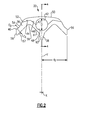
- Figure 2 shows wedge 32 having a radially outer full surface 50 extending into a curve 52 which begins circumferentially extending arms 36.
- the arms 36 extend for a relatively wide distance.
- Arm 36 includes a curved merging portion 54 which is curved about a radius of curvature C 0 which is spaced radially outwardly of the arm relative to a central axis X of the rotor that will receive the wedge 32.
- a circumferentially outermost curved contact portion 40 is curved about a radius of curvature centered on a point C 1 which is spaced inwardly of the surface 40. That is, curved contact portion 54 is curved inwardly while portion 40 is curved outwardly.
- a flat circumferentially outer surface or edge 56 of the arm is spaced by a distance d 1 from a plane Y which bisects wedge 32. In one embodiment, d 1 was 1.068 inches (2.713 centimeters).
- a flat radially inner surface 57 extends from edge 56 and then merges into a curve 59 and another flat portion 61 leading into the leg 38.
- Leg 38 has a generally triangular shape, such that a side 63 of the leg 38 extends radially inwardly at a greater angle than does flat surface 61.
- a ledge 44 does not extend radially outwardly as far as does full surface 50, and merges into a radially inwardly extending flat surface 46.
- Flat surface 46 ends at a point 47 at a center point of an aperture 42.
- Figure 3 shows the wedge 32 from a side.
- the ledge 44 defines a flat surface and extends along a center axis for an axial distance d 2 .
- d 2 was .812 inches (2.062 centimeters).
- a main body of the wedge including the full surface 50 extends for an axial distance d 3 .
- d 3 was 4.55 inches (11.6 centimeters).
- the circumferential width of the arms, dimension d 1 is relatively great.
- a ratio of d 1 to d 3 may be between 0.20 and 0.25.
- the d 1 dimension was 0.35 inches (8.89 mm) and the d 3 dimension was 2.8 inches (71.12 mm).
- a diameter D of aperture 42 is relatively great.
- D was .5 inch (1.27 centimeters).
- a ratio of D to d 3 was between 0.085 and 0.115.
- D was 0.25 inches (6.35 mm).
- Figure 4 shows the aperture 42 and a part aperture portion 48 which is found along the ledge 44.
- a machine 20 has a stator 22 and a rotor 24 including a lamination stack 28 having a plurality of poles 35 extending radially outwardly from a central axis.
- the poles 35 have pole tips 34 extending circumferentially at circumferential sides of the poles 35.
- Field coils 30/31 are wound around each pole piece. Between any two adjacent poles 35 there are portions of two field coils 30/31. Wedges are positioned circumferentially intermediate portions of the field coils.
- One of the wedges 32 is removed and replaced.
- the replacement wedge 32 is structured as described above.
Landscapes
- Engineering & Computer Science (AREA)
- Power Engineering (AREA)
- Insulation, Fastening Of Motor, Generator Windings (AREA)
Abstract
Description
- This application relates to an interface between a generator/motor wedge and pole tips on a lamination retaining the wedge and coils.
- Generators/motors are known, and may include a lamination stack having poles that receive wound field coils. Wedges are generally placed to separate and support the field coils.
- In one known type of generator/motor, the lamination stack includes pole tips, which define a channel that captures a portion of the wedge and the field coils. In this prior art generator/motor, an interface surface between the pole tips and the wedges is generally polygonal, or along straight surfaces.
- During operation, the generator/motor rotor may rotate at very high speeds, and thus there are centrifugal forces placed on the pole tips, the coils and the wedges. In particular, the wedge and coil may move away from a designed position, and the interface between the wedge and the pole tip may no longer be along the desired straight surface. In some applications, the pole tip has contacted a surface of the wedge spaced circumferentially away from the desired contact surface.
- This undesired contact location creates a stress lever arm which is relatively long.
- It has been proposed to include a curved surface on the arms.
- A wedge for use in an electric machine has a central leg extending in a direction that will be radially inward when the wedge is mounted on a lamination stack. The wedge has arms extending in both circumferential directions from the central leg, with a circumferentially outermost part of the arms having a curved contact surface that will be radially outward, and a flat inner surface that will be radially inward when the wedge is mounted in the lamination stack. The wedge has a radially outer full surface defining a cylindrical aperture through an axial length of the wedge. There are ledge surfaces at each axial end of the full surface of the wedge. A curved merging portion on an outer surface of the arms merges into the curved contact surface. The curved merging portion is formed on a radius of curvature centered from a point that will be spaced radially outwardly of the arm when the wedge is mounted on a lamination stack. The curved contact portion is formed about a radius of curvature centered from a point that will be spaced radially inwardly of the curved contact surface when the wedge is mounted on a lamination stack.
- A rotor, a machine and a method are also disclosed.
- These and other features of the invention may be best understood from the following specification and drawings, the following of which is a brief description.
-
-
Figure 1 shows a generator/motor in section. -
Figure 2 shows a wedge. -
Figure 3 is a side view of the wedge. -
Figure 4 is a cross-sectional view along line 4-4 as shown inFigure 2 . -
Figure 1 shows a cross-section of amachine 20 that may operate as a generator or a motor. As known, arotor 24 includes acentral shaft 26, which is driven to rotate by a source of rotation, such as a gas turbine engine 27 (shown schematically)and adjacent to a stator 22 (shown schematically) to generate electricity. Therotor 24 includes alamination stack 28 havingpoles 35 with circumferentially extendingwedges 32. Thewedges 32 sit in a channel radially inwardly of circumferentially opposedpole tips 34 onpoles 35. The channels receive field coils orwindings 30 and 31, which are wound around thepoles 35. - The
wedge 32 separates and supportsadjacent coils 30 and 31. In this design, thewedge 32 has acentral leg 38 extending radially inwardly betweenadjacent coils 30 and 31, andarms 36 extending circumferentially to sit underneath thepole tips 34. Thecentral leg 38 may be significantly shorter in some applications. In thewedge 32 illustrated inFigure 1 , a circumferentiallyoutermost portion 40 of the wedge has a generally curved contact surface interface with thepole tip 34, for purposes to be described below. - A
band 65 sits on aledge 44 and secures thewedges 32. -
Figure 2 showswedge 32 having a radially outerfull surface 50 extending into acurve 52 which begins circumferentially extendingarms 36. Thearms 36 extend for a relatively wide distance.Arm 36 includes acurved merging portion 54 which is curved about a radius of curvature C0 which is spaced radially outwardly of the arm relative to a central axis X of the rotor that will receive thewedge 32. A circumferentially outermostcurved contact portion 40 is curved about a radius of curvature centered on a point C1 which is spaced inwardly of thesurface 40. That is,curved contact portion 54 is curved inwardly whileportion 40 is curved outwardly. A flat circumferentially outer surface oredge 56 of the arm is spaced by a distance d1 from a plane Y which bisects wedge 32. In one embodiment, d1 was 1.068 inches (2.713 centimeters). - A flat radially
inner surface 57 extends fromedge 56 and then merges into acurve 59 and anotherflat portion 61 leading into theleg 38.Leg 38 has a generally triangular shape, such that aside 63 of theleg 38 extends radially inwardly at a greater angle than doesflat surface 61. Aledge 44 does not extend radially outwardly as far as doesfull surface 50, and merges into a radially inwardly extendingflat surface 46.Flat surface 46 ends at apoint 47 at a center point of anaperture 42. -
Figure 3 shows thewedge 32 from a side. As shown, theledge 44 defines a flat surface and extends along a center axis for an axial distance d2. In one embodiment, d2 was .812 inches (2.062 centimeters). A main body of the wedge including thefull surface 50 extends for an axial distance d3. In one embodiment, d3 was 4.55 inches (11.6 centimeters). - In embodiments, the circumferential width of the arms, dimension d1 is relatively great. A ratio of d1 to d3 may be between 0.20 and 0.25. In the prior art, the d1 dimension was 0.35 inches (8.89 mm) and the d3 dimension was 2.8 inches (71.12 mm).
- Further, a diameter D of
aperture 42 is relatively great. In one embodiment, D was .5 inch (1.27 centimeters). In an embodiment, a ratio of D to d3 was between 0.085 and 0.115. In the prior art, D was 0.25 inches (6.35 mm). -
Figure 4 shows theaperture 42 and apart aperture portion 48 which is found along the ledge 44. - In a method, a
machine 20 has astator 22 and arotor 24 including alamination stack 28 having a plurality ofpoles 35 extending radially outwardly from a central axis. Thepoles 35 havepole tips 34 extending circumferentially at circumferential sides of thepoles 35.Field coils 30/31 are wound around each pole piece. Between any twoadjacent poles 35 there are portions of twofield coils 30/31. Wedges are positioned circumferentially intermediate portions of the field coils. One of thewedges 32 is removed and replaced. Thereplacement wedge 32 is structured as described above. - Although an embodiment of this invention has been disclosed, a worker of ordinary skill the art would recognize that certain modifications would come within the scope of this invention. For that reason, the following claims should be studied to determine the true scope and content of this invention.
Claims (10)
- A wedge (32) for use in an electric machine comprising:a central leg (38) extending in a direction that will be radially inward when the wedge (32) is mounted on a lamination stack, and said wedge (32) having arms (36) extending in both circumferential directions from said central leg (38), with a circumferentially outermost part of said arms (36) having a curved contact surface (40) that will be radially outward, and a flat inner surface (57) that will be radially inward when the wedge (32) in mounted in the lamination stack;said wedge (32) having a radially outer full surface (50) defining a cylindrical aperture (42) through an axial length of said full surface (50), and ledge surfaces (44) at each axial end of said full surface (50) of said wedge (32); anda curved merging portion (54) on an outer surface of said arms (36) merging into said curved contact surface (40), said curved merging portion (54) being formed on a radius of curvature centered from a point (C0) that will be spaced radially outwardly of said arm (36) when said wedge (32) is mounted on a lamination stack, and said curved contact portion (40) being formed about a radius of curvature centered on a point (C1) that will be spaced radially inwardly of said curved contact surface (40) when the wedge (32) is mounted on a lamination stack.
- The wedge for use in an electric machine as set forth in claim 1, wherein said aperture (42) defines a diameter (D) and said full surface (50) of said wedge (32) extends for an axial distance (d3), and a ratio of said diameter (D) to said axial distance (d3) being between 0.085 and 0.115.
- The wedge for use in an electric machine as set forth in claim 2, wherein a circumferential width (d3) is defined from a plane (Y) which bisects said wedge (32) to a circumferentially outer flat edge (56) on said arm (36), and a ratio of said circumferential width (d1) to said axial distance (d3) is between 0.20 and 0.25.
- The wedge for use in an electric machine as set forth in claim 1, wherein a circumferential width (d1) is defined from a plane (Y) which bisects said wedge (32) to a circumferentially outer flat edge (56) on said arm (36), and the full surface (50) extends for an axial distance (d3) and a ratio of said circumferential width (d1) to said axial distance (d3) being between 0.20 and 0.25.
- The wedge for use in an electric machine as set forth in claim 4, wherein said flat inner surface (57) extends from said edge (56), and merges into a merging flat surface (61) leading into the leg (38), said leg (38) has a generally triangular shape, and a side of the leg (38) extends radially inwardly at a greater angle than does merging flat surface (61), said ledges (44) do not extend radially outwardly as far as said full surface (50), and merge into a radially inwardly extending flat surface (46), which ends at a center point (47) of the cylindrical aperture (42).
- A machine (20) comprising:a stator (22);a rotor (24) including a lamination stack (28) having a plurality of poles (35) extending radially outwardly from a central axis, and said poles (35) having pole tips (34) extending circumferentially at circumferential sides of said poles (35), field coils (30,31) wound around each of said poles (35), such that between any two adjacent poles (35), there are portions of two field coils (30,31);a wedge (32) positioned circumferentially intermediate said portions of said field coils (30,31), with a central leg (38) extending radially inwardly to separate said portions of said field coils (30,31), and said wedge (32) having circumferentially extending arms (36) extending circumferentially to be radially inward of said pole tips (34) on said lamination stack (28), with a curved contact surface (40) on a circumferentially outermost portion of said wedge (32) being in contact with a surface on a radially inward portion of said pole tip (34);said wedge (32) having a radially outer full surface (50) defining a cylindrical aperture (42) through an axial length of said full surface (50), and ledge surfaces (44) at each axial end of said full surface of said wedge (32); anda curved merging portion (54) on an outer surface of said arms (36) merging into said curved contact surface (40), said curved merging portion (54) being formed on a radius of curvature centered from a point (C0) that will be spaced radially outwardly of said arm (36) when said wedge (32) is mounted on a lamination stack (28), and said curved contact portion (40) being formed about a radius of curvature centered on a point (C1) that will be spaced radially inwardly of said curved contact surface (40) when the wedge (32) is mounted on a lamination stack (28).
- The machine as set forth in claim 6, wherein said aperture (42) defines a diameter (D) and said full surface (50) of said wedge (32) extends for an axial distance (d3), and a ratio of said diameter (D) to said axial distance (d3) being between 0.085 and 0.115.
- The machine as set forth in claim 7, wherein a circumferential width (d1) is defined from a plane (Y) which bisects said wedge (32) to a circumferentially outer flat edge (56) on said arm (36), and a ratio of said circumferential width (d1) to said axial distance (d3) being between 0.20 and 0.25.
- The machine as set forth in claim 6, wherein a circumferential distance (d1) is defined from a plane (Y) which bisects said wedge (32) to a circumferentially outer flat edge (56) on said arm (36), and the full surface (50) extending for an axial distance (d3), and a ratio of said circumferential width (d1) and said first axial distance (d3) being between 0.20 and 0.25.
- A machine as set forth in claim 9, wherein said flat inner surface (57) extends from said edge (56), and merges into a merging flat surface (61) leading into the leg (36), said leg (36) has a generally triangular shape, and a side of the leg (36) extends radially inwardly at a greater angle than does merging flat surface (61), said ledges (44) do not extend radially outwardly as far as said full surface (50), and merge into a radially inwardly extending flat surface (46), which ends at a center point (47) of the cylindrical aperture (42).
Applications Claiming Priority (1)
| Application Number | Priority Date | Filing Date | Title |
|---|---|---|---|
| US14/512,676 US9866085B2 (en) | 2014-10-13 | 2014-10-13 | Generator motor wedge with wide arm span and reduced stress levels |
Publications (3)
| Publication Number | Publication Date |
|---|---|
| EP3010120A2 true EP3010120A2 (en) | 2016-04-20 |
| EP3010120A3 EP3010120A3 (en) | 2016-06-08 |
| EP3010120B1 EP3010120B1 (en) | 2017-07-12 |
Family
ID=54288714
Family Applications (1)
| Application Number | Title | Priority Date | Filing Date |
|---|---|---|---|
| EP15188918.5A Active EP3010120B1 (en) | 2014-10-13 | 2015-10-08 | Generator/motor wedge with wide arm span and reduced stress levels |
Country Status (2)
| Country | Link |
|---|---|
| US (1) | US9866085B2 (en) |
| EP (1) | EP3010120B1 (en) |
Families Citing this family (1)
| Publication number | Priority date | Publication date | Assignee | Title |
|---|---|---|---|---|
| US11081920B2 (en) * | 2017-09-29 | 2021-08-03 | Hamilton Sundstrand Corporation | Rotor wedges and layers and heat sinks |
Family Cites Families (10)
| Publication number | Priority date | Publication date | Assignee | Title |
|---|---|---|---|---|
| US6113024A (en) * | 1999-04-30 | 2000-09-05 | Alliedsignal Inc. | Winding wedge retention to maintain coil form |
| US6984910B2 (en) * | 2003-01-13 | 2006-01-10 | Honeywell International, Inc. | Generator with composite rotor coil retention components |
| GB0314636D0 (en) | 2003-06-24 | 2003-07-30 | Goodrich Control Sys Ltd | Dynamo electric machines |
| US7821171B2 (en) * | 2008-12-02 | 2010-10-26 | Hamilton Sundstrand Corporation | Generator wedge with reduced eddy current losses |
| US8018114B2 (en) * | 2009-03-26 | 2011-09-13 | Hamilton Sundstrand Corporation | Generator rotor with improved wedges |
| US20110291518A1 (en) * | 2010-05-28 | 2011-12-01 | Emerson Electric Company | Rotor assembly for a generator or a motor |
| US8232702B2 (en) | 2010-07-30 | 2012-07-31 | Ge Aviation Systems, Llc | Apparatus for a high speed sleeveless rotor |
| CN201839179U (en) | 2010-10-28 | 2011-05-18 | 陕西航空电气有限责任公司 | Rotor structure of aircraft generator |
| US9030074B2 (en) | 2012-05-04 | 2015-05-12 | Hamilton Sundstrand Corporation | Air-cooled generator rotor with improved wedges |
| US8853911B2 (en) | 2012-09-28 | 2014-10-07 | Hamilton Sundstrand Corporation | Generator/motor wedge with lamination interface for reduced stress levels |
-
2014
- 2014-10-13 US US14/512,676 patent/US9866085B2/en active Active
-
2015
- 2015-10-08 EP EP15188918.5A patent/EP3010120B1/en active Active
Non-Patent Citations (1)
| Title |
|---|
| None |
Also Published As
| Publication number | Publication date |
|---|---|
| EP3010120A3 (en) | 2016-06-08 |
| US20160105058A1 (en) | 2016-04-14 |
| US9866085B2 (en) | 2018-01-09 |
| EP3010120B1 (en) | 2017-07-12 |
Similar Documents
| Publication | Publication Date | Title |
|---|---|---|
| US7821171B2 (en) | Generator wedge with reduced eddy current losses | |
| US8018114B2 (en) | Generator rotor with improved wedges | |
| US11355986B2 (en) | Rotor with a winding for an electrical machine | |
| EP3046230B1 (en) | Rotor wedge for generator | |
| MX2016005934A (en) | Single-phase outer-rotor motor and stator thereof. | |
| EP3046229A1 (en) | Rotor wedge with arms | |
| EP3223412A1 (en) | Induction motor | |
| US10439458B2 (en) | Permanent magnet rotor for rotary electric machine | |
| EP2975741A2 (en) | Rotor cooling | |
| KR20180081705A (en) | A rotary electric machine comprising a rotor and a stator for passing fluid therethrough | |
| EP2595287A3 (en) | Cooling structure for brushless motor | |
| CN104113168A (en) | Flaring System For Flaring Stator Windings | |
| EP2713482A2 (en) | Generator/Motor wedge with lamination interface for reduced stress levels | |
| EP3352344A1 (en) | Vehicular ac power generator | |
| US20160172911A1 (en) | Rotary electric machine | |
| US20170070110A1 (en) | Rotary electrical machine comprising a shaft with stepped diameters, and method for assembly of a machine of this type | |
| US20140300240A1 (en) | Electric machine rotor | |
| US10644555B2 (en) | Winding support | |
| CN106487183A (en) | Electric machine | |
| US9030074B2 (en) | Air-cooled generator rotor with improved wedges | |
| US9866085B2 (en) | Generator motor wedge with wide arm span and reduced stress levels | |
| US20200248704A1 (en) | Electric media gap machine, and compressor and/or turbine | |
| EP4024673B1 (en) | Wedge for rotor field coils and rotor comprising the same | |
| US20150022036A1 (en) | Rotor with non-cylindrical surface for dynamoelectric machine | |
| EP3306789A1 (en) | Rotor of vehicular alternator |
Legal Events
| Date | Code | Title | Description |
|---|---|---|---|
| PUAI | Public reference made under article 153(3) epc to a published international application that has entered the european phase |
Free format text: ORIGINAL CODE: 0009012 |
|
| AK | Designated contracting states |
Kind code of ref document: A2 Designated state(s): AL AT BE BG CH CY CZ DE DK EE ES FI FR GB GR HR HU IE IS IT LI LT LU LV MC MK MT NL NO PL PT RO RS SE SI SK SM TR |
|
| AX | Request for extension of the european patent |
Extension state: BA ME |
|
| PUAL | Search report despatched |
Free format text: ORIGINAL CODE: 0009013 |
|
| AK | Designated contracting states |
Kind code of ref document: A3 Designated state(s): AL AT BE BG CH CY CZ DE DK EE ES FI FR GB GR HR HU IE IS IT LI LT LU LV MC MK MT NL NO PL PT RO RS SE SI SK SM TR |
|
| AX | Request for extension of the european patent |
Extension state: BA ME |
|
| RIC1 | Information provided on ipc code assigned before grant |
Ipc: H02K 3/487 20060101AFI20160502BHEP |
|
| STAA | Information on the status of an ep patent application or granted ep patent |
Free format text: STATUS: REQUEST FOR EXAMINATION WAS MADE |
|
| 17P | Request for examination filed |
Effective date: 20161207 |
|
| RBV | Designated contracting states (corrected) |
Designated state(s): AL AT BE BG CH CY CZ DE DK EE ES FI FR GB GR HR HU IE IS IT LI LT LU LV MC MK MT NL NO PL PT RO RS SE SI SK SM TR |
|
| GRAP | Despatch of communication of intention to grant a patent |
Free format text: ORIGINAL CODE: EPIDOSNIGR1 |
|
| STAA | Information on the status of an ep patent application or granted ep patent |
Free format text: STATUS: GRANT OF PATENT IS INTENDED |
|
| INTG | Intention to grant announced |
Effective date: 20170321 |
|
| GRAS | Grant fee paid |
Free format text: ORIGINAL CODE: EPIDOSNIGR3 |
|
| GRAA | (expected) grant |
Free format text: ORIGINAL CODE: 0009210 |
|
| STAA | Information on the status of an ep patent application or granted ep patent |
Free format text: STATUS: THE PATENT HAS BEEN GRANTED |
|
| AK | Designated contracting states |
Kind code of ref document: B1 Designated state(s): AL AT BE BG CH CY CZ DE DK EE ES FI FR GB GR HR HU IE IS IT LI LT LU LV MC MK MT NL NO PL PT RO RS SE SI SK SM TR |
|
| REG | Reference to a national code |
Ref country code: GB Ref legal event code: FG4D |
|
| REG | Reference to a national code |
Ref country code: CH Ref legal event code: EP |
|
| REG | Reference to a national code |
Ref country code: AT Ref legal event code: REF Ref document number: 909182 Country of ref document: AT Kind code of ref document: T Effective date: 20170715 |
|
| REG | Reference to a national code |
Ref country code: IE Ref legal event code: FG4D |
|
| REG | Reference to a national code |
Ref country code: DE Ref legal event code: R096 Ref document number: 602015003530 Country of ref document: DE |
|
| REG | Reference to a national code |
Ref country code: FR Ref legal event code: PLFP Year of fee payment: 3 |
|
| REG | Reference to a national code |
Ref country code: NL Ref legal event code: MP Effective date: 20170712 |
|
| REG | Reference to a national code |
Ref country code: LT Ref legal event code: MG4D |
|
| REG | Reference to a national code |
Ref country code: AT Ref legal event code: MK05 Ref document number: 909182 Country of ref document: AT Kind code of ref document: T Effective date: 20170712 |
|
| PG25 | Lapsed in a contracting state [announced via postgrant information from national office to epo] |
Ref country code: AT Free format text: LAPSE BECAUSE OF FAILURE TO SUBMIT A TRANSLATION OF THE DESCRIPTION OR TO PAY THE FEE WITHIN THE PRESCRIBED TIME-LIMIT Effective date: 20170712 Ref country code: LT Free format text: LAPSE BECAUSE OF FAILURE TO SUBMIT A TRANSLATION OF THE DESCRIPTION OR TO PAY THE FEE WITHIN THE PRESCRIBED TIME-LIMIT Effective date: 20170712 Ref country code: NL Free format text: LAPSE BECAUSE OF FAILURE TO SUBMIT A TRANSLATION OF THE DESCRIPTION OR TO PAY THE FEE WITHIN THE PRESCRIBED TIME-LIMIT Effective date: 20170712 Ref country code: NO Free format text: LAPSE BECAUSE OF FAILURE TO SUBMIT A TRANSLATION OF THE DESCRIPTION OR TO PAY THE FEE WITHIN THE PRESCRIBED TIME-LIMIT Effective date: 20171012 Ref country code: FI Free format text: LAPSE BECAUSE OF FAILURE TO SUBMIT A TRANSLATION OF THE DESCRIPTION OR TO PAY THE FEE WITHIN THE PRESCRIBED TIME-LIMIT Effective date: 20170712 Ref country code: HR Free format text: LAPSE BECAUSE OF FAILURE TO SUBMIT A TRANSLATION OF THE DESCRIPTION OR TO PAY THE FEE WITHIN THE PRESCRIBED TIME-LIMIT Effective date: 20170712 Ref country code: SE Free format text: LAPSE BECAUSE OF FAILURE TO SUBMIT A TRANSLATION OF THE DESCRIPTION OR TO PAY THE FEE WITHIN THE PRESCRIBED TIME-LIMIT Effective date: 20170712 |
|
| PG25 | Lapsed in a contracting state [announced via postgrant information from national office to epo] |
Ref country code: LV Free format text: LAPSE BECAUSE OF FAILURE TO SUBMIT A TRANSLATION OF THE DESCRIPTION OR TO PAY THE FEE WITHIN THE PRESCRIBED TIME-LIMIT Effective date: 20170712 Ref country code: IS Free format text: LAPSE BECAUSE OF FAILURE TO SUBMIT A TRANSLATION OF THE DESCRIPTION OR TO PAY THE FEE WITHIN THE PRESCRIBED TIME-LIMIT Effective date: 20171112 Ref country code: BG Free format text: LAPSE BECAUSE OF FAILURE TO SUBMIT A TRANSLATION OF THE DESCRIPTION OR TO PAY THE FEE WITHIN THE PRESCRIBED TIME-LIMIT Effective date: 20171012 Ref country code: PL Free format text: LAPSE BECAUSE OF FAILURE TO SUBMIT A TRANSLATION OF THE DESCRIPTION OR TO PAY THE FEE WITHIN THE PRESCRIBED TIME-LIMIT Effective date: 20170712 Ref country code: ES Free format text: LAPSE BECAUSE OF FAILURE TO SUBMIT A TRANSLATION OF THE DESCRIPTION OR TO PAY THE FEE WITHIN THE PRESCRIBED TIME-LIMIT Effective date: 20170712 Ref country code: RS Free format text: LAPSE BECAUSE OF FAILURE TO SUBMIT A TRANSLATION OF THE DESCRIPTION OR TO PAY THE FEE WITHIN THE PRESCRIBED TIME-LIMIT Effective date: 20170712 Ref country code: GR Free format text: LAPSE BECAUSE OF FAILURE TO SUBMIT A TRANSLATION OF THE DESCRIPTION OR TO PAY THE FEE WITHIN THE PRESCRIBED TIME-LIMIT Effective date: 20171013 |
|
| REG | Reference to a national code |
Ref country code: DE Ref legal event code: R097 Ref document number: 602015003530 Country of ref document: DE |
|
| PG25 | Lapsed in a contracting state [announced via postgrant information from national office to epo] |
Ref country code: RO Free format text: LAPSE BECAUSE OF FAILURE TO SUBMIT A TRANSLATION OF THE DESCRIPTION OR TO PAY THE FEE WITHIN THE PRESCRIBED TIME-LIMIT Effective date: 20170712 Ref country code: DK Free format text: LAPSE BECAUSE OF FAILURE TO SUBMIT A TRANSLATION OF THE DESCRIPTION OR TO PAY THE FEE WITHIN THE PRESCRIBED TIME-LIMIT Effective date: 20170712 Ref country code: CZ Free format text: LAPSE BECAUSE OF FAILURE TO SUBMIT A TRANSLATION OF THE DESCRIPTION OR TO PAY THE FEE WITHIN THE PRESCRIBED TIME-LIMIT Effective date: 20170712 |
|
| PLBE | No opposition filed within time limit |
Free format text: ORIGINAL CODE: 0009261 |
|
| STAA | Information on the status of an ep patent application or granted ep patent |
Free format text: STATUS: NO OPPOSITION FILED WITHIN TIME LIMIT |
|
| PG25 | Lapsed in a contracting state [announced via postgrant information from national office to epo] |
Ref country code: EE Free format text: LAPSE BECAUSE OF FAILURE TO SUBMIT A TRANSLATION OF THE DESCRIPTION OR TO PAY THE FEE WITHIN THE PRESCRIBED TIME-LIMIT Effective date: 20170712 Ref country code: SK Free format text: LAPSE BECAUSE OF FAILURE TO SUBMIT A TRANSLATION OF THE DESCRIPTION OR TO PAY THE FEE WITHIN THE PRESCRIBED TIME-LIMIT Effective date: 20170712 Ref country code: MC Free format text: LAPSE BECAUSE OF FAILURE TO SUBMIT A TRANSLATION OF THE DESCRIPTION OR TO PAY THE FEE WITHIN THE PRESCRIBED TIME-LIMIT Effective date: 20170712 Ref country code: SM Free format text: LAPSE BECAUSE OF FAILURE TO SUBMIT A TRANSLATION OF THE DESCRIPTION OR TO PAY THE FEE WITHIN THE PRESCRIBED TIME-LIMIT Effective date: 20170712 Ref country code: IT Free format text: LAPSE BECAUSE OF FAILURE TO SUBMIT A TRANSLATION OF THE DESCRIPTION OR TO PAY THE FEE WITHIN THE PRESCRIBED TIME-LIMIT Effective date: 20170712 |
|
| 26N | No opposition filed |
Effective date: 20180413 |
|
| REG | Reference to a national code |
Ref country code: IE Ref legal event code: MM4A |
|
| PG25 | Lapsed in a contracting state [announced via postgrant information from national office to epo] |
Ref country code: LU Free format text: LAPSE BECAUSE OF NON-PAYMENT OF DUE FEES Effective date: 20171008 |
|
| REG | Reference to a national code |
Ref country code: BE Ref legal event code: MM Effective date: 20171031 |
|
| PG25 | Lapsed in a contracting state [announced via postgrant information from national office to epo] |
Ref country code: SI Free format text: LAPSE BECAUSE OF FAILURE TO SUBMIT A TRANSLATION OF THE DESCRIPTION OR TO PAY THE FEE WITHIN THE PRESCRIBED TIME-LIMIT Effective date: 20170712 Ref country code: BE Free format text: LAPSE BECAUSE OF NON-PAYMENT OF DUE FEES Effective date: 20171031 |
|
| REG | Reference to a national code |
Ref country code: FR Ref legal event code: PLFP Year of fee payment: 4 |
|
| PG25 | Lapsed in a contracting state [announced via postgrant information from national office to epo] |
Ref country code: MT Free format text: LAPSE BECAUSE OF NON-PAYMENT OF DUE FEES Effective date: 20171008 |
|
| PG25 | Lapsed in a contracting state [announced via postgrant information from national office to epo] |
Ref country code: IE Free format text: LAPSE BECAUSE OF NON-PAYMENT OF DUE FEES Effective date: 20171008 |
|
| REG | Reference to a national code |
Ref country code: CH Ref legal event code: PL |
|
| PG25 | Lapsed in a contracting state [announced via postgrant information from national office to epo] |
Ref country code: HU Free format text: LAPSE BECAUSE OF FAILURE TO SUBMIT A TRANSLATION OF THE DESCRIPTION OR TO PAY THE FEE WITHIN THE PRESCRIBED TIME-LIMIT; INVALID AB INITIO Effective date: 20151008 |
|
| PG25 | Lapsed in a contracting state [announced via postgrant information from national office to epo] |
Ref country code: LI Free format text: LAPSE BECAUSE OF NON-PAYMENT OF DUE FEES Effective date: 20181031 Ref country code: CH Free format text: LAPSE BECAUSE OF NON-PAYMENT OF DUE FEES Effective date: 20181031 |
|
| PG25 | Lapsed in a contracting state [announced via postgrant information from national office to epo] |
Ref country code: CY Free format text: LAPSE BECAUSE OF FAILURE TO SUBMIT A TRANSLATION OF THE DESCRIPTION OR TO PAY THE FEE WITHIN THE PRESCRIBED TIME-LIMIT Effective date: 20170712 |
|
| PG25 | Lapsed in a contracting state [announced via postgrant information from national office to epo] |
Ref country code: MK Free format text: LAPSE BECAUSE OF FAILURE TO SUBMIT A TRANSLATION OF THE DESCRIPTION OR TO PAY THE FEE WITHIN THE PRESCRIBED TIME-LIMIT Effective date: 20170712 |
|
| PGFP | Annual fee paid to national office [announced via postgrant information from national office to epo] |
Ref country code: DE Payment date: 20190918 Year of fee payment: 5 |
|
| PG25 | Lapsed in a contracting state [announced via postgrant information from national office to epo] |
Ref country code: TR Free format text: LAPSE BECAUSE OF FAILURE TO SUBMIT A TRANSLATION OF THE DESCRIPTION OR TO PAY THE FEE WITHIN THE PRESCRIBED TIME-LIMIT Effective date: 20170712 |
|
| PG25 | Lapsed in a contracting state [announced via postgrant information from national office to epo] |
Ref country code: PT Free format text: LAPSE BECAUSE OF FAILURE TO SUBMIT A TRANSLATION OF THE DESCRIPTION OR TO PAY THE FEE WITHIN THE PRESCRIBED TIME-LIMIT Effective date: 20170712 |
|
| PG25 | Lapsed in a contracting state [announced via postgrant information from national office to epo] |
Ref country code: AL Free format text: LAPSE BECAUSE OF FAILURE TO SUBMIT A TRANSLATION OF THE DESCRIPTION OR TO PAY THE FEE WITHIN THE PRESCRIBED TIME-LIMIT Effective date: 20170712 |
|
| REG | Reference to a national code |
Ref country code: DE Ref legal event code: R119 Ref document number: 602015003530 Country of ref document: DE |
|
| PG25 | Lapsed in a contracting state [announced via postgrant information from national office to epo] |
Ref country code: DE Free format text: LAPSE BECAUSE OF NON-PAYMENT OF DUE FEES Effective date: 20210501 |
|
| P01 | Opt-out of the competence of the unified patent court (upc) registered |
Effective date: 20230522 |
|
| PGFP | Annual fee paid to national office [announced via postgrant information from national office to epo] |
Ref country code: GB Payment date: 20250923 Year of fee payment: 11 |
|
| PGFP | Annual fee paid to national office [announced via postgrant information from national office to epo] |
Ref country code: FR Payment date: 20250924 Year of fee payment: 11 |