EP3009856A1 - Method and system for determining a relative position to a target - Google Patents
Method and system for determining a relative position to a target Download PDFInfo
- Publication number
- EP3009856A1 EP3009856A1 EP15382230.9A EP15382230A EP3009856A1 EP 3009856 A1 EP3009856 A1 EP 3009856A1 EP 15382230 A EP15382230 A EP 15382230A EP 3009856 A1 EP3009856 A1 EP 3009856A1
- Authority
- EP
- European Patent Office
- Prior art keywords
- transmitter
- target
- optical frequency
- relative angular
- light
- Prior art date
- Legal status (The legal status is an assumption and is not a legal conclusion. Google has not performed a legal analysis and makes no representation as to the accuracy of the status listed.)
- Granted
Links
Images


Classifications
-
- G—PHYSICS
- G01—MEASURING; TESTING
- G01C—MEASURING DISTANCES, LEVELS OR BEARINGS; SURVEYING; NAVIGATION; GYROSCOPIC INSTRUMENTS; PHOTOGRAMMETRY OR VIDEOGRAMMETRY
- G01C21/00—Navigation; Navigational instruments not provided for in groups G01C1/00 - G01C19/00
- G01C21/20—Instruments for performing navigational calculations
-
- G—PHYSICS
- G01—MEASURING; TESTING
- G01B—MEASURING LENGTH, THICKNESS OR SIMILAR LINEAR DIMENSIONS; MEASURING ANGLES; MEASURING AREAS; MEASURING IRREGULARITIES OF SURFACES OR CONTOURS
- G01B11/00—Measuring arrangements characterised by the use of optical techniques
- G01B11/26—Measuring arrangements characterised by the use of optical techniques for measuring angles or tapers; for testing the alignment of axes
-
- G—PHYSICS
- G01—MEASURING; TESTING
- G01S—RADIO DIRECTION-FINDING; RADIO NAVIGATION; DETERMINING DISTANCE OR VELOCITY BY USE OF RADIO WAVES; LOCATING OR PRESENCE-DETECTING BY USE OF THE REFLECTION OR RERADIATION OF RADIO WAVES; ANALOGOUS ARRANGEMENTS USING OTHER WAVES
- G01S1/00—Beacons or beacon systems transmitting signals having a characteristic or characteristics capable of being detected by non-directional receivers and defining directions, positions, or position lines fixed relatively to the beacon transmitters; Receivers co-operating therewith
- G01S1/70—Beacons or beacon systems transmitting signals having a characteristic or characteristics capable of being detected by non-directional receivers and defining directions, positions, or position lines fixed relatively to the beacon transmitters; Receivers co-operating therewith using electromagnetic waves other than radio waves
- G01S1/703—Details
- G01S1/7032—Transmitters
- G01S1/7034—Mounting or deployment thereof
-
- G—PHYSICS
- G01—MEASURING; TESTING
- G01S—RADIO DIRECTION-FINDING; RADIO NAVIGATION; DETERMINING DISTANCE OR VELOCITY BY USE OF RADIO WAVES; LOCATING OR PRESENCE-DETECTING BY USE OF THE REFLECTION OR RERADIATION OF RADIO WAVES; ANALOGOUS ARRANGEMENTS USING OTHER WAVES
- G01S1/00—Beacons or beacon systems transmitting signals having a characteristic or characteristics capable of being detected by non-directional receivers and defining directions, positions, or position lines fixed relatively to the beacon transmitters; Receivers co-operating therewith
- G01S1/70—Beacons or beacon systems transmitting signals having a characteristic or characteristics capable of being detected by non-directional receivers and defining directions, positions, or position lines fixed relatively to the beacon transmitters; Receivers co-operating therewith using electromagnetic waves other than radio waves
- G01S1/703—Details
- G01S1/7032—Transmitters
- G01S1/7038—Signal details
-
- G—PHYSICS
- G01—MEASURING; TESTING
- G01S—RADIO DIRECTION-FINDING; RADIO NAVIGATION; DETERMINING DISTANCE OR VELOCITY BY USE OF RADIO WAVES; LOCATING OR PRESENCE-DETECTING BY USE OF THE REFLECTION OR RERADIATION OF RADIO WAVES; ANALOGOUS ARRANGEMENTS USING OTHER WAVES
- G01S17/00—Systems using the reflection or reradiation of electromagnetic waves other than radio waves, e.g. lidar systems
- G01S17/02—Systems using the reflection of electromagnetic waves other than radio waves
- G01S17/06—Systems determining position data of a target
- G01S17/42—Simultaneous measurement of distance and other co-ordinates
-
- G—PHYSICS
- G01—MEASURING; TESTING
- G01S—RADIO DIRECTION-FINDING; RADIO NAVIGATION; DETERMINING DISTANCE OR VELOCITY BY USE OF RADIO WAVES; LOCATING OR PRESENCE-DETECTING BY USE OF THE REFLECTION OR RERADIATION OF RADIO WAVES; ANALOGOUS ARRANGEMENTS USING OTHER WAVES
- G01S5/00—Position-fixing by co-ordinating two or more direction or position line determinations; Position-fixing by co-ordinating two or more distance determinations
- G01S5/16—Position-fixing by co-ordinating two or more direction or position line determinations; Position-fixing by co-ordinating two or more distance determinations using electromagnetic waves other than radio waves
- G01S5/163—Determination of attitude
-
- G—PHYSICS
- G01—MEASURING; TESTING
- G01S—RADIO DIRECTION-FINDING; RADIO NAVIGATION; DETERMINING DISTANCE OR VELOCITY BY USE OF RADIO WAVES; LOCATING OR PRESENCE-DETECTING BY USE OF THE REFLECTION OR RERADIATION OF RADIO WAVES; ANALOGOUS ARRANGEMENTS USING OTHER WAVES
- G01S7/00—Details of systems according to groups G01S13/00, G01S15/00, G01S17/00
- G01S7/48—Details of systems according to groups G01S13/00, G01S15/00, G01S17/00 of systems according to group G01S17/00
- G01S7/4808—Evaluating distance, position or velocity data
-
- G—PHYSICS
- G01—MEASURING; TESTING
- G01S—RADIO DIRECTION-FINDING; RADIO NAVIGATION; DETERMINING DISTANCE OR VELOCITY BY USE OF RADIO WAVES; LOCATING OR PRESENCE-DETECTING BY USE OF THE REFLECTION OR RERADIATION OF RADIO WAVES; ANALOGOUS ARRANGEMENTS USING OTHER WAVES
- G01S2201/00—Indexing scheme relating to beacons or beacon systems transmitting signals capable of being detected by non-directional receivers and defining directions, positions, or position lines fixed relatively to the beacon transmitters
- G01S2201/01—Indexing scheme relating to beacons or beacon systems transmitting signals capable of being detected by non-directional receivers and defining directions, positions, or position lines fixed relatively to the beacon transmitters adapted for specific applications or environments
- G01S2201/06—Aircraft navigation
Definitions
- the present invention relates generally to the field of relative navigation systems and methods of relative navigation.
- Relative navigation systems are useful for various applications such as autonomous vehicle navigation, mid-air refueling, and space docking. In some applications, only the range between two objects is required.
- the invention relates to Optoelectronic instrumentation systems and the generation and use of OFCGs (Optical Frequency Combs Generators) for determining the relative position of a target.
- OFCGs Optical Frequency Combs Generators
- Relative navigation systems are useful for various applications such as autonomous vehicle navigation, mid-air refuelling, and space docking.
- range and the relative attitude (pitch, yaw, and roll) between two objects are required.
- Such information is typically gathered as a time series and used to make course corrections in one or more of the objects to enable a desired manoeuvre or final relative position.
- US8326523 discloses a method of determining a range between first and second objects with relative movement, where a plurality of grid lines from a first origin point on the first object are projected into space. Each of the grid lines is modulated to carry a grid word to identify each grid line within the grid. The grid lines and the corresponding grid words are detected from at least three locations having a predetermined triangular relationship on the second object defining vertices. An angle is based on the location within the grid of each of the vertices. The range between the first and second objects is determined based on the set of angles.
- US8352100 describes a method of providing a relative navigation system by projecting a grid defining a first relative reference frame associated with a first origin, the grid being repeatedly detected from a second object having a second relative reference frame associated with a second origin point on a second object.
- the attitude or range of at least one of the first and second objects is adjusted based on the determined range and relative attitude measured.
- US8872081 describes a method for stabilizing a grid projected from a grid generator which includes determining a change in the reference frame of the grid generator relative to prior grid projection, and altering the grid data of a subsequent grid projection such that the subsequent grid projection appears stabilized relative to a prior grid projection.
- the present invention provides an alternative solution for determining the relative angular direction ⁇ between a target and a transmitter by a method according to claim 1
- a method for determining a relative position between a target and a transmitter in an area wherein relative position is defined by the parameters relative angular direction and distance, according to claim 8, a system for determining the relative angular direction between a target and a transmitter according to claim 9 and a system for determining a relative position between a target and a transmitter according to claim 14.
- Dependent claims define particular embodiments of the invention. All the features described in this specification (including the claims, description and drawings) and/or all the steps of the described method can be combined in any combination, with the exception of combinations of such mutually exclusive features and/or steps.
- a method for determining the relative angular direction ⁇ between a target and a transmitter comprising the following steps:
- a light beam indicates a relative angular direction from the transmitter
- the generation of the one or more light beams comprises diffracting broadband light in such a way that different optical frequency wavelengths are ditfracted differently and a relative angular direction ⁇ is detected by reading the optical frequency wavelength.
- broadband light is to be understood as a radiation in the optical (or infrared) wavelength range characterized by a wide spectral coverage (continuous or discrete) around a central wavelength.
- Reading of the optical frequency wavelength may be performed by a spectrometer, in such a way that the angular position in space is determined or indicated by the light beam which is received or read. In terms of colours, this might be understood as receiving the yellow colour out from an initial beam which is diffracted. The yellow colour is diffracted in a specific angular direction by, for example, a diffraction grating. Therefore if the element configured to read the optical frequency wavelength which is received, for example the spectrometer is configured to relate the yellow colour with a determined or specific angular direction in an area, then the determination is made.
- the broadband light which is generated is not a continuous optical spectrum; this is to say, broadband light comprises discrete spectral lines (super continuum) or multimode light.
- At least the multimode light comprises an optical frequency comb.
- a frequency comb is a light beam whose spectrum consists of a series of discrete, equally spaced elements. Frequency combs may be generated by
- the light beam which is transmitted comprises a dual comb which is, in turn, diffracted.
- Frequency combing the multimode light with a second reference signal, a second Optical Frequency Comb at a different repetition rate allows measuring a received wavelength by mapping the optical frequencies into radio or electronic frequencies.
- Advantageously measuring radio frequencies require less sophisticated equipment for easier and quicker to perform than measuring by a spectrometer.
- f r is much smaller than f o .
- At least a light beam comprises two dual frequency combs comprising different repetition rates said two dual frequency combs being transmitted in two different directions forming a grid in two angular directions.
- this allows positioning a target in two angular directions in such a way that, if the directions are perpendicular to each other, it is possible to differentiate height and width.
- the combination of a dual comb and a diffraction grating allows detecting a relative angular direction ⁇ by reading an electronic frequency associated to a mixing between the different modes.
- the relative angular direction ⁇ is determined by the target receiving the one or more light beams. This is the case of having an active target, where the target is able to know its position and the position is forwarded by the active target to the transmitter for both to know the position.
- the relative angular ⁇ direction is further determined by the transmitter receiving the reflection of the one or more light beams from the target. This allows the use of passive targets. This embodiment is opposite or complementary to the previous case. In the case of having a passive target, the target reflects the beam; the detector in the transmitter receives the reflection of the passive target with no need of forwarding the beam by any active target. In certain embodiments both the transmitter and the target determine the relative angular ⁇ direction; advantageously redundancy makes the method more reliable.
- a method allows determining the pitch and yaw or yaw and roll of an aircraft in flight when it enters an area of detection.
- a method according to the invention comprises determining a position between a target and a transmitter, wherein relative position is defined by the parameters
- This embodiment advantageously allows the detection of, not only the angular position or pitch and yaw or yaw and roll of an aircraft in flight, but also the third dimension or distance to a target or aircraft.
- determining an angular position and distance to a target is performed using at least three detectors.
- the solution of the resent invention allows determining the third dimension with the use of two detectors.
- a system for determining the relative angular direction between a target and a transmitter configured to generate light beams wherein the generation of the one or more light beams comprises diffracting broadband light in such a way that different optical frequency wavelengths are diffracted differently and a relative angular direction ⁇ is detected by reading the optical frequency wavelength, comprising
- Means configured to determine the relative angular direction are means may be, for example, computer means, or a microprocessor or a device configured to determine relative angular direction by reading an optical frequency wavelength of the one or more light beams.
- the computer means, or microprocessor or device may be in connection to a photodetector which receives and reads the light beams and the computer means, or microprocessor or device translates the optical frequency to electronic frequency.
- system further comprises a grid generator, preferably two cylindrical lenses.
- system further comprises an aircraft wherein the aircraft comprises the target.
- system further comprises a further aircraft wherein the further aircraft comprises the transmitter.
- the means configured to determine the distance (d) between the target and the transmitter by triangulation may be computer means, or a microprocessor configured to compute a distance by triangulation, given relative angular direction ( ⁇ 1 , ⁇ 2 ) and a predetermined distance between the two or more receptors.
- system further comprises a grid generator, preferably two cylindrical lenses.
- grid may cover a wide area in space, for example, and a relative position may be determined with two coordinates.
- system further comprises an aircraft wherein the aircraft comprises the target.
- system further comprises a further aircraft wherein the further aircraft comprises the transmitter.
- the invention allows the relative position between two aircrafts be determined in a short period of time in comparison with the systems and methods of the state of the art.
- This solution combines spectrometric techniques with optic concepts such as diffraction so that a relative position between two elements may be determined, for example for determining the relative position between two aircrafts in flight.
- the examples below relate generally to a system for the determination of angular and relative positions between two objects, particularly between a target (1) and transmitter (2).
- Figure 1 represents a transmitter 2, which may be installed on tanker aircraft, and a receiver (1).
- the transmitter (2) comprises
- the transmitter (2) comprises the following features (in one axis):
- the receiver (1) in figure 1 comprises
- the transmitter (2) is configured to produce of the one or more light beams (3) and at least two optical frequency combs in a dual Optical Frequency comb configuration:
- the described example uses a high-frequency modulation.
- the frequencies used in this example are:
- the wavelengths of both combs are identical from the point of view of diffraction ( ⁇ / ⁇ 1) so the analysis for only one of them may be performed as follows, for example for a central wavelength of 1550 nm, and having regard of figure 2 .
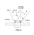
- FIG 2 a diffraction grating functioning in reflection is shown.
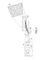
- Figure 3 shows a series of entities which may be comprised in a system according to the invention, in the transmitter (2).
- Figure 3 shows:
- the recovering of the electronica frequency (fout) will be implemented digitally using an FPGA with implementing FFTs.
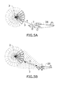
- Figure 5A shows an example of the relative angular direction ⁇ being determined by a target, an aircraft (28), receiving the one or more light beams (3). This is the case of having an active target in the aircraft (28), where the target is able to know its position and the position is forwarded by the active target or aircraft (28) to the transmitter (2), which may be a further aircraft, for both to know the position.
- Figure 5B shows an example of the relative angular ⁇ direction being determined by the transmitter (2) receiving the reflection of the one or more light beams (3) from the target (28).
- This allows the use of passive targets.
- This embodiment is opposite or complementary to the previous case.
- the target reflects the beam; a detector in the transmitter (2) receives the reflection of the passive target with no need of forwarding the beam (3) by any active target.
- the proposed system is able to provide with two coordinates (yaw and roll), a third coordinate (distance) to be necessary to obtain the position of the object.
- the relative position is defined by the parameters
- Figure 6 shows a system (30) comprising
- the system (30) in figure 5 further comprises
- the receiver may comprise a retroreflector for avoiding the whole aircraft reflecting a wide area of beams (3).
- the retroreflector may be mounted, for example on the wings of the airplane to provide with the two locations to extract also the third dimension.
Landscapes
- Physics & Mathematics (AREA)
- Engineering & Computer Science (AREA)
- Radar, Positioning & Navigation (AREA)
- Remote Sensing (AREA)
- General Physics & Mathematics (AREA)
- Electromagnetism (AREA)
- Computer Networks & Wireless Communication (AREA)
- Automation & Control Theory (AREA)
- Length Measuring Devices By Optical Means (AREA)
Abstract
- relative angular direction (θ1, θ2) and
- distance (d).
Description
- The present invention relates generally to the field of relative navigation systems and methods of relative navigation. Relative navigation systems are useful for various applications such as autonomous vehicle navigation, mid-air refueling, and space docking. In some applications, only the range between two objects is required. More particularly, the invention relates to Optoelectronic instrumentation systems and the generation and use of OFCGs (Optical Frequency Combs Generators) for determining the relative position of a target.
- Relative navigation systems are useful for various applications such as autonomous vehicle navigation, mid-air refuelling, and space docking. In some applications the range and the relative attitude (pitch, yaw, and roll) between two objects are required. Such information is typically gathered as a time series and used to make course corrections in one or more of the objects to enable a desired manoeuvre or final relative position.
-
US8326523 discloses a method of determining a range between first and second objects with relative movement, where a plurality of grid lines from a first origin point on the first object are projected into space. Each of the grid lines is modulated to carry a grid word to identify each grid line within the grid. The grid lines and the corresponding grid words are detected from at least three locations having a predetermined triangular relationship on the second object defining vertices. An angle is based on the location within the grid of each of the vertices. The range between the first and second objects is determined based on the set of angles. -
US8352100 describes a method of providing a relative navigation system by projecting a grid defining a first relative reference frame associated with a first origin, the grid being repeatedly detected from a second object having a second relative reference frame associated with a second origin point on a second object. The attitude or range of at least one of the first and second objects is adjusted based on the determined range and relative attitude measured. -
US8872081 describes a method for stabilizing a grid projected from a grid generator which includes determining a change in the reference frame of the grid generator relative to prior grid projection, and altering the grid data of a subsequent grid projection such that the subsequent grid projection appears stabilized relative to a prior grid projection. - The above mentioned solutions of the state of the art implement time consuming algorithms for acknowledging the relative position of a target and they usually depend on more than one detector or system, such as two grids, for the detection of for example an aircraft.
- The present invention provides an alternative solution for determining the relative angular direction θ between a target and a transmitter by a method according to
claim 1 There is also provided a method for determining a relative position between a target and a transmitter in an area, wherein relative position is defined by the parameters relative angular direction and distance, according toclaim 8, a system for determining the relative angular direction between a target and a transmitter according toclaim 9 and a system for determining a relative position between a target and a transmitter according to claim 14. Dependent claims define particular embodiments of the invention. All the features described in this specification (including the claims, description and drawings) and/or all the steps of the described method can be combined in any combination, with the exception of combinations of such mutually exclusive features and/or steps. - In particular, in a first aspect of the invention there is provided a method for determining the relative angular direction θ between a target and a transmitter, the method comprising the following steps:
- -transmitting by the transmitter such one or more light beams, wherein a light beam indicates a relative angular direction from the transmitter,
- -receiving by the target one or more of the light beams,
characterized in that the generation of the one or more light beams comprises diffracting broadband light in such a way that different optical frequency wavelengths are ditfracted differently and a relative angular direction θ is detected by reading the optical frequency wavelength. - In the present description, broadband light is to be understood as a radiation in the optical (or infrared) wavelength range characterized by a wide spectral coverage (continuous or discrete) around a central wavelength.
- Reading of the optical frequency wavelength may be performed by a spectrometer, in such a way that the angular position in space is determined or indicated by the light beam which is received or read. In terms of colours, this might be understood as receiving the yellow colour out from an initial beam which is diffracted. The yellow colour is diffracted in a specific angular direction by, for example, a diffraction grating. Therefore if the element configured to read the optical frequency wavelength which is received, for example the spectrometer is configured to relate the yellow colour with a determined or specific angular direction in an area, then the determination is made.
- In certain embodiments the broadband light which is generated is not a continuous optical spectrum; this is to say, broadband light comprises discrete spectral lines (super continuum) or multimode light.
- In certain embodiments at least the multimode light comprises an optical frequency comb.
- A frequency comb is a light beam whose spectrum consists of a series of discrete, equally spaced elements. Frequency combs may be generated by
- amplitude modulation of a continuous wave laser or
- stabilization of a pulse train generated by a mode locked laser.
- The frequency domain representation of a perfect frequency comb is a series of delta functions spaced according to

where - n is an integer, which corresponds to different colors
- fr is the comb tooth spacing or mode repetition rate,
- f 0 is the carrier offset frequency, which is less than fr. This frequency is in the optical domain (fo = 200 THz for a wavelength of 1.5 micron).
- Several methods may be used to obtain fr and fo.
- In certain embodiments at least a light beam comprises at least two optical frequency combs or Dual Frequency comb:
- a first optical frequency comb and
- a second optical frequency comb,
- first and second frequency combs comprising the same fo and comprising respective f r1 and f r2 where f r1 is different from f r2 , and
- fr is the comb tooth spacing or mode repetition rate,
- f 0 is the carrier offset frequency.
- In other words, the light beam which is transmitted comprises a dual comb which is, in turn, diffracted.
- Frequency combing the multimode light with a second reference signal, a second Optical Frequency Comb at a different repetition rate, allows measuring a received wavelength by mapping the optical frequencies into radio or electronic frequencies. Advantageously measuring radio frequencies require less sophisticated equipment for easier and quicker to perform than measuring by a spectrometer.
- In a preferred embodiment fr is much smaller than fo. For example, fr / fo ∼10-9 and Δf=f r1 -f r2 << fr 1, f r2 .
- In certain embodiments at least a light beam comprises two dual frequency combs comprising different repetition rates said two dual frequency combs being transmitted in two different directions forming a grid in two angular directions. Advantageously this allows positioning a target in two angular directions in such a way that, if the directions are perpendicular to each other, it is possible to differentiate height and width.
- The combination of a dual comb and a diffraction grating allows detecting a relative angular direction θ by reading an electronic frequency associated to a mixing between the different modes.
- In certain embodiments the relative angular direction θ is determined by the target receiving the one or more light beams. This is the case of having an active target, where the target is able to know its position and the position is forwarded by the active target to the transmitter for both to know the position.
- In certain embodiments the relative angular θ direction is further determined by the transmitter receiving the reflection of the one or more light beams from the target. This allows the use of passive targets. This embodiment is opposite or complementary to the previous case. In the case of having a passive target, the target reflects the beam; the detector in the transmitter receives the reflection of the passive target with no need of forwarding the beam by any active target. In certain embodiments both the transmitter and the target determine the relative angular θ direction; advantageously redundancy makes the method more reliable.
- A method according to the above mentioned embodiments allows determining the pitch and yaw or yaw and roll of an aircraft in flight when it enters an area of detection.
- In certain embodiments a method according to the invention comprises determining a position between a target and a transmitter, wherein relative position is defined by the parameters
- relative angular direction and
- distance,
- determining two or more relative angular directions θ1, θ2 between two or more receptors comprised in the target and the transmitter by a method according to the invention, and
- determining the distance between the target and the transmitter by triangulation, given a predetermined distance be
- This embodiment advantageously allows the detection of, not only the angular position or pitch and yaw or yaw and roll of an aircraft in flight, but also the third dimension or distance to a target or aircraft. In the state of the art, determining an angular position and distance to a target is performed using at least three detectors. As a difference, the solution of the resent invention allows determining the third dimension with the use of two detectors.
- In a second aspect of the invention there is provided a system for determining the relative angular direction between a target and a transmitter configured to generate light beams wherein the generation of the one or more light beams comprises diffracting broadband light in such a way that different optical frequency wavelengths are diffracted differently and a relative angular direction θ is detected by reading the optical frequency wavelength, comprising
- a transmitter comprising
- one or more broadband light sources,
- one or more diffraction grating, configured to receive broadband light from the broadband light source,
- a target comprising
- ▪ one or more receptors configured to receive one or more light beams generated by a method according to the first aspect of the invention,
- ▪ means in connection with the one or more receptors configured to determine the relative angular direction by reading the optical frequency wavelength by a method according to the first aspect of the invention.
- Means configured to determine the relative angular direction are means may be, for example, computer means, or a microprocessor or a device configured to determine relative angular direction by reading an optical frequency wavelength of the one or more light beams. The computer means, or microprocessor or device may be in connection to a photodetector which receives and reads the light beams and the computer means, or microprocessor or device translates the optical frequency to electronic frequency.
- In certain embodiments the system comprises
- one or more multimode light sources comprising
- a monomode light source, for example a laser light source, and
- one or more dual-optical frequency comb generator OFCG configured to receive light from the monomode light source
- one or more diffraction grating, configured to receive the Dual Optical Frequency Comb from the OFCG, and
- means configured to determine the relative angular direction by reading an optical frequency wavelength of the one or more light beams, said frequency wavelength related to an electronic frequency received by the receptor.
- In certain embodiments the system further comprises a grid generator, preferably two cylindrical lenses.
- In certain embodiments the system further comprises an aircraft wherein the aircraft comprises the target.
- In certain embodiments the system further comprises a further aircraft wherein the further aircraft comprises the transmitter.
- In a further aspect of the invention there is provided a system for determining a relative position between a target and a transmitter in an area, wherein relative position is defined by the parameters
- relative angular direction (θ1, θ2) and
- distance (d),
- a transmitter configured to generate light beams wherein the generation of the one or more light beams comprises diffracting broadband light in such a way that different optical frequency wavelengths are diffracted differently and a relative angular direction θ is detected by reading the optical frequency wavelength, the transmitter comprising
- one or more broadband light sources,
- one or more diffraction grating,
- a target comprising two or more receptors,
- means in connection with the two or more receptors, said means configured to determine two or more relative angular directions θ1, θ2 by reading two or more optical frequency wavelengths by a method according to the first aspect of the invention, and
- means configured to determine the distance (d) between the target and the transmitter by triangulation, given a predetermined distance between the two or more receptors and the two or more relative angular directions θ1,θ2 according to the first aspect of the invention.
- The means configured to determine the distance (d) between the target and the transmitter by triangulation may be computer means, or a microprocessor configured to compute a distance by triangulation, given relative angular direction (θ1, θ2) and a predetermined distance between the two or more receptors.
- In certain embodiments the system further comprises a grid generator, preferably two cylindrical lenses. Advantageously the grid may cover a wide area in space, for example, and a relative position may be determined with two coordinates.
- In certain embodiments the system further comprises an aircraft wherein the aircraft comprises the target.
- In certain embodiments the system further comprises a further aircraft wherein the further aircraft comprises the transmitter. Advantageously, the invention allows the relative position between two aircrafts be determined in a short period of time in comparison with the systems and methods of the state of the art.
- This solution combines spectrometric techniques with optic concepts such as diffraction so that a relative position between two elements may be determined, for example for determining the relative position between two aircrafts in flight.
- In the state of the art relative positions are measured using monomode laser lights amplitude modulated. The invention advantageously allows obtaining a space sweep with the use of a single source, taking advantage of diffraction into multiple modes.
- These and other characteristics and advantages of the invention will become clearly understood in view of the detailed description of the invention which becomes apparent from a preferred embodiment of the invention, given just as an example and not being limited thereto, with reference to the drawings.
- Figures 1
- This figure shows a system according to the invention.
- Figures 2
- This figure represents a diffraction grating and the principle of reflection of two parallel rays, and the influence of the wavelength of the incident light in the reflection angle.
- Figure 3
- This figure shows the transmitter part of a system according to the invention.
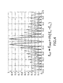
- Figure 4
- This figure represents the optical spectrum of the dual-comb source and the received frequency associated to the mixing of the superimposed lobes shown in the figure as Δf=fr 1-f r2 << f r1, f r2
- Figure 5A
- This figure shows a transmitter and an active detector according to the invention.
- Figure 5B
- This figure shows a transmitter and an passive detector according to the invention.
- Figure 6
- This figure shows a system according to the invention where the distance is calculated by a method according to the invention.
- The examples below relate generally to a system for the determination of angular and relative positions between two objects, particularly between a target (1) and transmitter (2).
-
Figure 1 represents atransmitter 2, which may be installed on tanker aircraft, and a receiver (1). - The transmitter (2) comprises
- a broadband light source (4) comprising
- a monomode light source (41),
- an optical frequency comb generator OFCG (42), configured to receive the light (10) from the monomode light source (41), and configured to generate the multimode light (5) or optical frequency comb (5).
- one or more diffraction grating (25), configured to receive the Optical Frequency Comb (5) from the OFCG (42).
- In a particular example the transmitter (2) comprises the following features (in one axis):
- 35° cone coverage
- Angular resolution = 0.005 ° to 30 meters (7000 lobes are estimated)
- Opening of the lobe in the orthogonal direction = 35 °
- Transmission of signal in the optical domain, particularly in the infrared range used for optical communications (Wave length = 1550 nm). This provides several benefits:
- Low cost associated to the use of communications components,
- High spatial resolution (angular) due to the low wavelength used,
- Wave length traditionally "Eye-safe".
- The receiver (1) in
figure 1 comprises - a receptor (26), with the capacity to read the incident light wavelength (spectrometer) configured to receive one or more light beams (3) from one or more diffraction grating (25),
- means (29) for determining the relative angular direction by reading the incident light wavelength in connection with the receptor (26).
- The transmitter (2) is configured to produce of the one or more light beams (3) and at least two optical frequency combs in a dual Optical Frequency comb configuration:
- a first optical frequency comb and
- a second optical frequency comb,
- first and second frequency combs comprising the same fo and comprising respective f r1 and f r2 where f r1 is different from f r2, and
- f r1, f r2 is the comb tooth spacing or mode repetition rate,
- f 0 is the carrier offset frequency.
- The described example uses a high-frequency modulation. The frequencies used in this example are:
- f 0 = 200 THz (λ= 1500 nm, telecom wavelength).
- f r1 = 10 GHz,
- f r2 = 10, 00001 GHz,
- Being such a small difference frequencies, the wavelengths of both combs are identical from the point of view of diffraction (Δλ/λ<<1) so the analysis for only one of them may be performed as follows, for example for a central wavelength of 1550 nm, and having regard of
figure 2 . - In
figure 2 a diffraction grating functioning in reflection is shown. Given a standard grating of 1000 lines / mm (d = 1 µmm), for the given central wavelength the grating equation indicates that d(sin a + sinβ= λ); given c=λ*f; ∂β/ ∂α, and Δf=f r1-f r2 =10GHz results in ∂β∼0.1 mrad. Therefore 0.1mrad per line = 0.005° per grid line. The fact that the separation between two lobes (m, m + 1) is 0.1 mrad implies that 35°/0.005° = 7000 lines are required at least to have a measurement range of 35°. As the angular separation ∂β is given by f r1 and f r1 (that can be adjusted), the invention allows reducing the number of grid lines required by having ∂β=1 mrad, either changing f r1 and f r1 or using various gratings in cascaded to increase the divergence angle. -
Figure 3 shows a series of entities which may be comprised in a system according to the invention, in the transmitter (2).Figure 3 shows: - a light source (41),
- a dual optical frequency comb generator OFCG (42), configured to receive the light (10) from the light source (41),
- one or more diffraction grating (25), configured to receive one or more dual Optical Frequency Comb (5) from the OFCG (42),
- a grid generator (27), for example a couple of cylindrical lenses, from which a grid (9) is formed.
- Other data for the transmitter
- issued Power: 5 W
- Number of lines: 700
- losses in the optical: 10 dB
- divergence collimator: 0.047°
- spot width in the orthogonal direction (35 ° to 30 m): 9.46 m
- output spot diameter: 12 mm
- spot size on detection: 76 x 9460 mm.
- With these data, the power received in reception may be: Prec= 75 nW.
- In a particular example the transmitter may comprise an acousto-optic modulator in the OFCG in such a manner that it inserts an offset frequency, fAOM, so that in the direction θ=0 the detector would solve a positive frequency instead of a frequency of 0 Hz.
- In detection the two Optical Frequency Combs (5) are overlapped, or the wavelengths of both combs are identical from the point of view of diffraction (Δλ/λ<<1), so the actual electronic frequency detected (in the case of using an acoustooptic modulator) is fout = fAOM + m (f r1 - f r2)= fAOM + m 10kHz. This is represented in
figure 4 , where "m" represents the modes or "colors" of the received light. For example, for m=0, the yellow color is obtained by detecting a frequency of fout= fAOM, so that it would mean an angular position respective to yellow color. For m=1 the orange would be obtained, so it is possible to know the color and therefore the direction by detecting the frequency fout= fAOM + m 10KHz. - The recovering of the electronica frequency (fout) will be implemented digitally using an FPGA with implementing FFTs.
- In a first approximation, there are two possible alternatives to implement a two-axis, ie, to extract information uniquely yaw and roll.
- 1. Wavelength Division: In this case two combs may be used on two different wavelengths (1550 nm and 1310 nm to leverage standard communications components). This approach requires different listeners for each of the axes, which doubles the detection electronics.
- 2. Division in the frequency domain: In this case the two dual combs produce different outputs fout: fout = fAOM + m (f r1 - f r2)= fAOM + m 10kHz. (10, 20, 30 KHz for the first dual comb or axis) and fout= fAOM + 5 kHz+m 10KHz (15, 25 kHz for the second dual comb or axis) may be used. This would bring the following implications:
- same sensors and the same detection electronics may be used (no need to double the detection system);
- the detection electronics need to be modified slightly increasing its frequency resolution (larger FPGA), however this can help with aspects associated to noise bandwidth;
- it is highly desirable to synchronize the transmitter and receiver.
-
Figure 5A shows an example of the relative angular direction θ being determined by a target, an aircraft (28), receiving the one or more light beams (3). This is the case of having an active target in the aircraft (28), where the target is able to know its position and the position is forwarded by the active target or aircraft (28) to the transmitter (2), which may be a further aircraft, for both to know the position. -
Figure 5B shows an example of the relative angular θ direction being determined by the transmitter (2) receiving the reflection of the one or more light beams (3) from the target (28). This allows the use of passive targets. This embodiment is opposite or complementary to the previous case. In the case of having a passive target infigure 5B , the target reflects the beam; a detector in the transmitter (2) receives the reflection of the passive target with no need of forwarding the beam (3) by any active target. - The proposed system is able to provide with two coordinates (yaw and roll), a third coordinate (distance) to be necessary to obtain the position of the object. This is represented in
figure 6 where a system (30) for determining a relative position between a target (1) and a transmitter (2). In this example the relative position is defined by the parameters - relative angular direction (θ1, θ2) and
- distance (d).
-
Figure 6 shows a system (30) comprising - a transmitter (2) and
- a target (1) comprising two receptors (7, 8), for example photodiodes.
- The system (30) in
figure 5 further comprises - means (31) in connection with the two or more receptors (7, 8), said means (31) configured to determine two or more relative angular directions θ1, θ2 by reading two or more electronic frequencies, and
- means (32) configured to determine the distance (d) between the target (1) and the transmitter (2) by triangulation, given a predetermined distance (6) between the two or more receptors (7, 8) and the two or more relative angular directions θ1,θ2.
- Some of the advantages of a method according to the invention are:
- quick measurements since an electronic frequency is to be detected instead of scanning a laser light; this entails that it is possible to detect several targets in a short period of time;
- possibility of working with passive receptors;
- It may allow guidance of an aircraft during the approach path to a tanker aircraft;
- The size of the detected object is no relevant in the case of an active detector;
- In the case of a passive target the receiver may comprise a retroreflector for avoiding the whole aircraft reflecting a wide area of beams (3). The retroreflector may be mounted, for example on the wings of the airplane to provide with the two locations to extract also the third dimension.
Claims (15)
- A method for determining the relative angular direction θ between a target (1) and a transmitter (2), the method comprising the following steps:- producing one or more light beams (3),- transmitting by the transmitter (2) such one or more light beams (3), wherein a light beam (3) indicates a relative angular direction from the transmitter (2),- receiving by the target (1) one or more of the light beams (3),wherein the generation of the one or more light beams (3) comprises diffracting broadband light (5) in such a way that different optical frequency wavelengths are diffracted differently and a relative angular direction θ is detected by reading the optical frequency wavelength.
- A method according to claim 1 wherein broadband light (5) comprises discrete spectral lines or multimode light.
- A method according to claim 1 or 2 wherein the broadband light (5) or the multimode light comprises an optical frequency comb (5).
- A method according to claim 3 wherein at least a light beam (3) comprises at least two optical frequency combs (5) or dual frequency comb, comprising:- a first optical frequency comb and- a second optical frequency comb,- first and second frequency combs comprising the same fo and comprising respective f r1 and f r2 where f r1 is different from f r2, andwherein- f r1 , fr2 is the comb tooth spacing or mode repetition rate,- f 0 is the carrier offset frequency.
- A method according to claim 4 wherein at least a light beam (3) comprises two dual frequency combs comprising different repetition rates, said two dual frequency combs being transmitted in two different directions forming a grid (9) in two angular directions.
- A method according to any of previous claims wherein the relative angular direction θ is determined by the target (1) receiving the one or more light beams (3).
- A method according to any of previous claims wherein the relative angular θ direction is determined by the transmitter (2) receiving the reflection of the one or more light beams (3) from the target (1).
- A method for determining a relative position between a target (1) and a transmitter (2) in an area, wherein relative position is defined by the parameters- relative angular direction and- distance (d),the method comprising the steps of:- determining two or more relative angular directions θ1, θ2 between two or more receptors (7, 8), comprised in the target (1), and the transmitter (2) by respective methods according to any of claims 1 to 7, and- determining the distance between the target (1) and the transmitter (2) by triangulation, given a predetermined distance (6) between the two or more receptors (7, 8) and the two or more relative angular directions θ1, θ2.
- System (20) for determining the relative angular direction between a target (1) and a transmitter (2) configured to generate light beams (3) wherein the generation of the one or more light beams (3) comprises diffracting broadband light (5) in such a way that different optical frequency wavelengths are diffracted differently and a relative angular direction θ is detected by reading the optical frequency wavelength, comprising- a transmitter (2) comprisingand- one or more broadband light sources (4),- one or more diffraction grating (25), configured to receive broadband light from the broadband light source (4),- a target (1) comprising- one or more receptors (26) configured to receive one or more light beams (3) generated by a method according to any of claims 1 to 8,- means (29) in connection with the one or more receptors (26) configured to determine the relative angular direction by reading the optical frequency wavelength according to a method of any of claims 1 to 8.
- System (20) according to claim 9 wherein- the broadband light source (4) comprises:- a monomode light source (41), for example a laser light source, and- one or more optical frequency comb generators OFCG (42), configured to receive the light (10) from the monomode light source (41),- and the optical frequency wavelength is related to an electronic frequency which is received by the receptor (26).
- System (20) according to any of claims 9 to 10 further comprising a grid generator (27), preferably two cylindrical lenses.
- System according to any of claims 9 or 11 further comprising an aircraft (28) wherein the aircraft comprises the target (1).
- System according to any of claims 9 to 12 comprising a further aircraft wherein the further aircraft comprises the transmitter (2).
- System (30) for determining a relative position between a target (1) and a transmitter (2) in an area, wherein relative position is defined by the parameters- relative angular direction (θ1, θ2) and- distance (d),the system (30) comprising- a transmitter (2) configured to generate light beams (3) wherein the generation of the one or more light beams (3) comprises diffracting broadband light (5) in such a way that different optical frequency wavelengths are diffracted differently and a relative angular direction θ is detected by reading the optical frequency wavelength, the transmitter (2) comprising- one or more broadband light sources (4),- one or more diffraction grating (25),and- a target (1) comprising- two or more receptors (7, 8),- means (29, 31) in connection with the two or more receptors (7, 8), said means (29, 31) configured to determine two or more relative angular directions θ1, θ2 by reading two or more optical frequency wavelengths by a method according to any of claims 1 to 8, and- means (32) configured to determine the distance (d) between the target (1) and the transmitter (2) by triangulation, given a predetermined distance (6) between the two or more receptors (7, 8) and the two or more relative angular directions θ1,θ2.
- System (30) according to claim 14 wherein- the broadband light source (4) comprises:- a monomode light source, for example a laser light source, and- one or more optical frequency comb generators OFCG (42), configured to receive the light (10) from the monomode light source (41),- and the optical frequency wavelength is related to an electronic frequency which is received by the receptor (26).
Priority Applications (3)
| Application Number | Priority Date | Filing Date | Title |
|---|---|---|---|
| EP15382230.9A EP3009856B1 (en) | 2015-05-05 | 2015-05-05 | Method and system for determining a relative position to a target |
| ES15382230.9T ES2642115T3 (en) | 2015-05-05 | 2015-05-05 | Method and system to determine a relative position with respect to an objective |
| US15/146,684 US10215569B2 (en) | 2015-05-05 | 2016-05-04 | Method and system for determining a relative position to a target |
Applications Claiming Priority (1)
| Application Number | Priority Date | Filing Date | Title |
|---|---|---|---|
| EP15382230.9A EP3009856B1 (en) | 2015-05-05 | 2015-05-05 | Method and system for determining a relative position to a target |
Publications (2)
| Publication Number | Publication Date |
|---|---|
| EP3009856A1 true EP3009856A1 (en) | 2016-04-20 |
| EP3009856B1 EP3009856B1 (en) | 2017-07-05 |
Family
ID=53181219
Family Applications (1)
| Application Number | Title | Priority Date | Filing Date |
|---|---|---|---|
| EP15382230.9A Active EP3009856B1 (en) | 2015-05-05 | 2015-05-05 | Method and system for determining a relative position to a target |
Country Status (3)
| Country | Link |
|---|---|
| US (1) | US10215569B2 (en) |
| EP (1) | EP3009856B1 (en) |
| ES (1) | ES2642115T3 (en) |
Cited By (2)
| Publication number | Priority date | Publication date | Assignee | Title |
|---|---|---|---|---|
| CN109839102A (en) * | 2017-11-27 | 2019-06-04 | 灵踪科技(深圳)有限公司 | Light curved surface localization method and device |
| US10443812B2 (en) | 2016-06-10 | 2019-10-15 | General Electric Company | Vehicle navigational system |
Families Citing this family (2)
| Publication number | Priority date | Publication date | Assignee | Title |
|---|---|---|---|---|
| US9147405B2 (en) * | 2013-12-05 | 2015-09-29 | Seagate Technology Llc | Light source alignment |
| WO2020064224A1 (en) * | 2018-09-27 | 2020-04-02 | Carl Zeiss Smt Gmbh | Apparatus and method for determining the distance of an object by scanning |
Citations (5)
| Publication number | Priority date | Publication date | Assignee | Title |
|---|---|---|---|---|
| US3710335A (en) * | 1970-05-20 | 1973-01-09 | L Lepley | Azimuthal positioning system |
| US8314928B2 (en) * | 2003-12-22 | 2012-11-20 | Eye Point Ltd. | High precision wide-angle electro-optical positioning system and method |
| US8326523B2 (en) | 2009-12-22 | 2012-12-04 | General Electric Company | Method of determining range |
| US8352100B2 (en) | 2009-12-22 | 2013-01-08 | General Electric Company | Relative navigation system and a method thereof |
| US8872081B2 (en) | 2011-11-01 | 2014-10-28 | Ge Aviation Systems Llc | Methods for adjusting a relative navigation system |
Family Cites Families (1)
| Publication number | Priority date | Publication date | Assignee | Title |
|---|---|---|---|---|
| US5200792A (en) * | 1989-08-31 | 1993-04-06 | Nec Corporation | Device for obtaining distance information from an object by instantaneously illuminating the object by a light beam |
-
2015
- 2015-05-05 EP EP15382230.9A patent/EP3009856B1/en active Active
- 2015-05-05 ES ES15382230.9T patent/ES2642115T3/en active Active
-
2016
- 2016-05-04 US US15/146,684 patent/US10215569B2/en active Active
Patent Citations (5)
| Publication number | Priority date | Publication date | Assignee | Title |
|---|---|---|---|---|
| US3710335A (en) * | 1970-05-20 | 1973-01-09 | L Lepley | Azimuthal positioning system |
| US8314928B2 (en) * | 2003-12-22 | 2012-11-20 | Eye Point Ltd. | High precision wide-angle electro-optical positioning system and method |
| US8326523B2 (en) | 2009-12-22 | 2012-12-04 | General Electric Company | Method of determining range |
| US8352100B2 (en) | 2009-12-22 | 2013-01-08 | General Electric Company | Relative navigation system and a method thereof |
| US8872081B2 (en) | 2011-11-01 | 2014-10-28 | Ge Aviation Systems Llc | Methods for adjusting a relative navigation system |
Cited By (3)
| Publication number | Priority date | Publication date | Assignee | Title |
|---|---|---|---|---|
| US10443812B2 (en) | 2016-06-10 | 2019-10-15 | General Electric Company | Vehicle navigational system |
| CN109839102A (en) * | 2017-11-27 | 2019-06-04 | 灵踪科技(深圳)有限公司 | Light curved surface localization method and device |
| CN109839102B (en) * | 2017-11-27 | 2021-05-04 | 灵踪科技(深圳)有限公司 | Optical curved surface positioning method and device |
Also Published As
| Publication number | Publication date |
|---|---|
| ES2642115T3 (en) | 2017-11-15 |
| US10215569B2 (en) | 2019-02-26 |
| EP3009856B1 (en) | 2017-07-05 |
| US20160327398A1 (en) | 2016-11-10 |
Similar Documents
| Publication | Publication Date | Title |
|---|---|---|
| EP3973312B1 (en) | Frequency modulated scanning lidar with 360 degrees field of view | |
| EP3973314B1 (en) | 360 degrees field of view scanning lidar with no movable parts | |
| Feneyrou et al. | Frequency-modulated multifunction lidar for anemometry, range finding, and velocimetry—2. Experimental results | |
| US10379136B2 (en) | Laser radar device | |
| EP3428685B1 (en) | Laser radar device | |
| EP3531168A1 (en) | Data processing device, laser radar device, and wind measurement system | |
| EP1333297A2 (en) | Method and system for determining air turbulence using bi-static measurements | |
| US10295673B1 (en) | Nested interferometer for optical autocovariance lidar | |
| EP3009856B1 (en) | Method and system for determining a relative position to a target | |
| EP2937711A1 (en) | Method and system for the remote monitoring of the two/three-dimensional field of displacements and vibrations of objects/structures | |
| EP3973313B1 (en) | Methods for large angle field of view scanning lidar with no movable parts | |
| CN206411262U (en) | Multi-beam scanning apparatus | |
| EP3577424B1 (en) | Optical heterodyne detection of air pressure, temperature, and wind velocity and method | |
| EP3922964B1 (en) | Vibration detection method, signal processing device, and program | |
| US20120140237A1 (en) | Optical Device for Measuring Anemometer Parameters | |
| US11522606B2 (en) | Phase measurement method, signal processing device, and program | |
| Bruneau et al. | Direct-detection wind lidar operating with a multimode laser | |
| US3489495A (en) | Range finding instruments | |
| EP3985417A1 (en) | Remote airstream observation device, remote airstream observation method, and program | |
| EP1702197B1 (en) | High precision wide-angle electro-optical positioning system and method | |
| US11768291B1 (en) | High dynamic range ranging interferometer | |
| US20220236418A1 (en) | Lidar system comprising an interferential diffractive element and lidar imaging method | |
| US20260110630A1 (en) | Methods and systems for open path gas detection | |
| US20260133284A1 (en) | Method, transceiver station, identification means and system for identifying an object | |
| CN119881914B (en) | Parallel detection and processing method and device for dual-frequency modulated microcavity optical frequency comb radar single detector |
Legal Events
| Date | Code | Title | Description |
|---|---|---|---|
| PUAI | Public reference made under article 153(3) epc to a published international application that has entered the european phase |
Free format text: ORIGINAL CODE: 0009012 |
|
| AK | Designated contracting states |
Kind code of ref document: A1 Designated state(s): AL AT BE BG CH CY CZ DE DK EE ES FI FR GB GR HR HU IE IS IT LI LT LU LV MC MK MT NL NO PL PT RO RS SE SI SK SM TR |
|
| AX | Request for extension of the european patent |
Extension state: BA ME |
|
| 17P | Request for examination filed |
Effective date: 20160511 |
|
| RBV | Designated contracting states (corrected) |
Designated state(s): AL AT BE BG CH CY CZ DE DK EE ES FI FR GB GR HR HU IE IS IT LI LT LU LV MC MK MT NL NO PL PT RO RS SE SI SK SM TR |
|
| GRAP | Despatch of communication of intention to grant a patent |
Free format text: ORIGINAL CODE: EPIDOSNIGR1 |
|
| INTG | Intention to grant announced |
Effective date: 20161220 |
|
| GRAS | Grant fee paid |
Free format text: ORIGINAL CODE: EPIDOSNIGR3 |
|
| GRAA | (expected) grant |
Free format text: ORIGINAL CODE: 0009210 |
|
| AK | Designated contracting states |
Kind code of ref document: B1 Designated state(s): AL AT BE BG CH CY CZ DE DK EE ES FI FR GB GR HR HU IE IS IT LI LT LU LV MC MK MT NL NO PL PT RO RS SE SI SK SM TR |
|
| REG | Reference to a national code |
Ref country code: GB Ref legal event code: FG4D |
|
| REG | Reference to a national code |
Ref country code: CH Ref legal event code: EP |
|
| REG | Reference to a national code |
Ref country code: AT Ref legal event code: REF Ref document number: 906968 Country of ref document: AT Kind code of ref document: T Effective date: 20170715 |
|
| REG | Reference to a national code |
Ref country code: IE Ref legal event code: FG4D |
|
| REG | Reference to a national code |
Ref country code: DE Ref legal event code: R096 Ref document number: 602015003446 Country of ref document: DE |
|
| REG | Reference to a national code |
Ref country code: NL Ref legal event code: MP Effective date: 20170705 |
|
| REG | Reference to a national code |
Ref country code: ES Ref legal event code: FG2A Ref document number: 2642115 Country of ref document: ES Kind code of ref document: T3 Effective date: 20171115 Ref country code: AT Ref legal event code: MK05 Ref document number: 906968 Country of ref document: AT Kind code of ref document: T Effective date: 20170705 |
|
| REG | Reference to a national code |
Ref country code: LT Ref legal event code: MG4D |
|
| PG25 | Lapsed in a contracting state [announced via postgrant information from national office to epo] |
Ref country code: LT Free format text: LAPSE BECAUSE OF FAILURE TO SUBMIT A TRANSLATION OF THE DESCRIPTION OR TO PAY THE FEE WITHIN THE PRESCRIBED TIME-LIMIT Effective date: 20170705 Ref country code: NL Free format text: LAPSE BECAUSE OF FAILURE TO SUBMIT A TRANSLATION OF THE DESCRIPTION OR TO PAY THE FEE WITHIN THE PRESCRIBED TIME-LIMIT Effective date: 20170705 Ref country code: FI Free format text: LAPSE BECAUSE OF FAILURE TO SUBMIT A TRANSLATION OF THE DESCRIPTION OR TO PAY THE FEE WITHIN THE PRESCRIBED TIME-LIMIT Effective date: 20170705 Ref country code: SE Free format text: LAPSE BECAUSE OF FAILURE TO SUBMIT A TRANSLATION OF THE DESCRIPTION OR TO PAY THE FEE WITHIN THE PRESCRIBED TIME-LIMIT Effective date: 20170705 Ref country code: AT Free format text: LAPSE BECAUSE OF FAILURE TO SUBMIT A TRANSLATION OF THE DESCRIPTION OR TO PAY THE FEE WITHIN THE PRESCRIBED TIME-LIMIT Effective date: 20170705 Ref country code: HR Free format text: LAPSE BECAUSE OF FAILURE TO SUBMIT A TRANSLATION OF THE DESCRIPTION OR TO PAY THE FEE WITHIN THE PRESCRIBED TIME-LIMIT Effective date: 20170705 Ref country code: NO Free format text: LAPSE BECAUSE OF FAILURE TO SUBMIT A TRANSLATION OF THE DESCRIPTION OR TO PAY THE FEE WITHIN THE PRESCRIBED TIME-LIMIT Effective date: 20171005 |
|
| PG25 | Lapsed in a contracting state [announced via postgrant information from national office to epo] |
Ref country code: LV Free format text: LAPSE BECAUSE OF FAILURE TO SUBMIT A TRANSLATION OF THE DESCRIPTION OR TO PAY THE FEE WITHIN THE PRESCRIBED TIME-LIMIT Effective date: 20170705 Ref country code: PL Free format text: LAPSE BECAUSE OF FAILURE TO SUBMIT A TRANSLATION OF THE DESCRIPTION OR TO PAY THE FEE WITHIN THE PRESCRIBED TIME-LIMIT Effective date: 20170705 Ref country code: RS Free format text: LAPSE BECAUSE OF FAILURE TO SUBMIT A TRANSLATION OF THE DESCRIPTION OR TO PAY THE FEE WITHIN THE PRESCRIBED TIME-LIMIT Effective date: 20170705 Ref country code: GR Free format text: LAPSE BECAUSE OF FAILURE TO SUBMIT A TRANSLATION OF THE DESCRIPTION OR TO PAY THE FEE WITHIN THE PRESCRIBED TIME-LIMIT Effective date: 20171006 Ref country code: BG Free format text: LAPSE BECAUSE OF FAILURE TO SUBMIT A TRANSLATION OF THE DESCRIPTION OR TO PAY THE FEE WITHIN THE PRESCRIBED TIME-LIMIT Effective date: 20171005 Ref country code: IS Free format text: LAPSE BECAUSE OF FAILURE TO SUBMIT A TRANSLATION OF THE DESCRIPTION OR TO PAY THE FEE WITHIN THE PRESCRIBED TIME-LIMIT Effective date: 20171105 |
|
| REG | Reference to a national code |
Ref country code: DE Ref legal event code: R097 Ref document number: 602015003446 Country of ref document: DE |
|
| PG25 | Lapsed in a contracting state [announced via postgrant information from national office to epo] |
Ref country code: DK Free format text: LAPSE BECAUSE OF FAILURE TO SUBMIT A TRANSLATION OF THE DESCRIPTION OR TO PAY THE FEE WITHIN THE PRESCRIBED TIME-LIMIT Effective date: 20170705 Ref country code: RO Free format text: LAPSE BECAUSE OF FAILURE TO SUBMIT A TRANSLATION OF THE DESCRIPTION OR TO PAY THE FEE WITHIN THE PRESCRIBED TIME-LIMIT Effective date: 20170705 Ref country code: CZ Free format text: LAPSE BECAUSE OF FAILURE TO SUBMIT A TRANSLATION OF THE DESCRIPTION OR TO PAY THE FEE WITHIN THE PRESCRIBED TIME-LIMIT Effective date: 20170705 |
|
| PLBE | No opposition filed within time limit |
Free format text: ORIGINAL CODE: 0009261 |
|
| STAA | Information on the status of an ep patent application or granted ep patent |
Free format text: STATUS: NO OPPOSITION FILED WITHIN TIME LIMIT |
|
| PG25 | Lapsed in a contracting state [announced via postgrant information from national office to epo] |
Ref country code: EE Free format text: LAPSE BECAUSE OF FAILURE TO SUBMIT A TRANSLATION OF THE DESCRIPTION OR TO PAY THE FEE WITHIN THE PRESCRIBED TIME-LIMIT Effective date: 20170705 Ref country code: SM Free format text: LAPSE BECAUSE OF FAILURE TO SUBMIT A TRANSLATION OF THE DESCRIPTION OR TO PAY THE FEE WITHIN THE PRESCRIBED TIME-LIMIT Effective date: 20170705 Ref country code: SK Free format text: LAPSE BECAUSE OF FAILURE TO SUBMIT A TRANSLATION OF THE DESCRIPTION OR TO PAY THE FEE WITHIN THE PRESCRIBED TIME-LIMIT Effective date: 20170705 Ref country code: IT Free format text: LAPSE BECAUSE OF FAILURE TO SUBMIT A TRANSLATION OF THE DESCRIPTION OR TO PAY THE FEE WITHIN THE PRESCRIBED TIME-LIMIT Effective date: 20170705 |
|
| 26N | No opposition filed |
Effective date: 20180406 |
|
| PG25 | Lapsed in a contracting state [announced via postgrant information from national office to epo] |
Ref country code: SI Free format text: LAPSE BECAUSE OF FAILURE TO SUBMIT A TRANSLATION OF THE DESCRIPTION OR TO PAY THE FEE WITHIN THE PRESCRIBED TIME-LIMIT Effective date: 20170705 |
|
| REG | Reference to a national code |
Ref country code: DE Ref legal event code: R119 Ref document number: 602015003446 Country of ref document: DE |
|
| REG | Reference to a national code |
Ref country code: CH Ref legal event code: PL |
|
| REG | Reference to a national code |
Ref country code: BE Ref legal event code: MM Effective date: 20180531 |
|
| PG25 | Lapsed in a contracting state [announced via postgrant information from national office to epo] |
Ref country code: MC Free format text: LAPSE BECAUSE OF FAILURE TO SUBMIT A TRANSLATION OF THE DESCRIPTION OR TO PAY THE FEE WITHIN THE PRESCRIBED TIME-LIMIT Effective date: 20170705 |
|
| REG | Reference to a national code |
Ref country code: IE Ref legal event code: MM4A |
|
| PG25 | Lapsed in a contracting state [announced via postgrant information from national office to epo] |
Ref country code: CH Free format text: LAPSE BECAUSE OF NON-PAYMENT OF DUE FEES Effective date: 20180531 Ref country code: LI Free format text: LAPSE BECAUSE OF NON-PAYMENT OF DUE FEES Effective date: 20180531 |
|
| PG25 | Lapsed in a contracting state [announced via postgrant information from national office to epo] |
Ref country code: LU Free format text: LAPSE BECAUSE OF NON-PAYMENT OF DUE FEES Effective date: 20180505 |
|
| PG25 | Lapsed in a contracting state [announced via postgrant information from national office to epo] |
Ref country code: FR Free format text: LAPSE BECAUSE OF NON-PAYMENT OF DUE FEES Effective date: 20180531 Ref country code: IE Free format text: LAPSE BECAUSE OF NON-PAYMENT OF DUE FEES Effective date: 20180505 Ref country code: DE Free format text: LAPSE BECAUSE OF NON-PAYMENT OF DUE FEES Effective date: 20181201 |
|
| PG25 | Lapsed in a contracting state [announced via postgrant information from national office to epo] |
Ref country code: BE Free format text: LAPSE BECAUSE OF NON-PAYMENT OF DUE FEES Effective date: 20180531 |
|
| GBPC | Gb: european patent ceased through non-payment of renewal fee |
Effective date: 20190505 |
|
| PG25 | Lapsed in a contracting state [announced via postgrant information from national office to epo] |
Ref country code: MT Free format text: LAPSE BECAUSE OF NON-PAYMENT OF DUE FEES Effective date: 20180505 |
|
| PG25 | Lapsed in a contracting state [announced via postgrant information from national office to epo] |
Ref country code: TR Free format text: LAPSE BECAUSE OF FAILURE TO SUBMIT A TRANSLATION OF THE DESCRIPTION OR TO PAY THE FEE WITHIN THE PRESCRIBED TIME-LIMIT Effective date: 20170705 |
|
| PG25 | Lapsed in a contracting state [announced via postgrant information from national office to epo] |
Ref country code: GB Free format text: LAPSE BECAUSE OF NON-PAYMENT OF DUE FEES Effective date: 20190505 |
|
| PG25 | Lapsed in a contracting state [announced via postgrant information from national office to epo] |
Ref country code: PT Free format text: LAPSE BECAUSE OF FAILURE TO SUBMIT A TRANSLATION OF THE DESCRIPTION OR TO PAY THE FEE WITHIN THE PRESCRIBED TIME-LIMIT Effective date: 20170705 |
|
| PG25 | Lapsed in a contracting state [announced via postgrant information from national office to epo] |
Ref country code: CY Free format text: LAPSE BECAUSE OF FAILURE TO SUBMIT A TRANSLATION OF THE DESCRIPTION OR TO PAY THE FEE WITHIN THE PRESCRIBED TIME-LIMIT Effective date: 20170705 Ref country code: HU Free format text: LAPSE BECAUSE OF FAILURE TO SUBMIT A TRANSLATION OF THE DESCRIPTION OR TO PAY THE FEE WITHIN THE PRESCRIBED TIME-LIMIT; INVALID AB INITIO Effective date: 20150505 Ref country code: MK Free format text: LAPSE BECAUSE OF NON-PAYMENT OF DUE FEES Effective date: 20170705 |
|
| PG25 | Lapsed in a contracting state [announced via postgrant information from national office to epo] |
Ref country code: AL Free format text: LAPSE BECAUSE OF FAILURE TO SUBMIT A TRANSLATION OF THE DESCRIPTION OR TO PAY THE FEE WITHIN THE PRESCRIBED TIME-LIMIT Effective date: 20170705 |
|
| PGFP | Annual fee paid to national office [announced via postgrant information from national office to epo] |
Ref country code: ES Payment date: 20250627 Year of fee payment: 11 |