EP3009758B1 - Humidifier - Google Patents
Humidifier Download PDFInfo
- Publication number
- EP3009758B1 EP3009758B1 EP15187541.6A EP15187541A EP3009758B1 EP 3009758 B1 EP3009758 B1 EP 3009758B1 EP 15187541 A EP15187541 A EP 15187541A EP 3009758 B1 EP3009758 B1 EP 3009758B1
- Authority
- EP
- European Patent Office
- Prior art keywords
- disk
- assembly
- case
- driving
- disposed
- Prior art date
- Legal status (The legal status is an assumption and is not a legal conclusion. Google has not performed a legal analysis and makes no representation as to the accuracy of the status listed.)
- Active
Links
- XLYOFNOQVPJJNP-UHFFFAOYSA-N water Substances O XLYOFNOQVPJJNP-UHFFFAOYSA-N 0.000 claims description 103
- 239000008400 supply water Substances 0.000 claims description 3
- 238000007664 blowing Methods 0.000 description 11
- 238000004140 cleaning Methods 0.000 description 5
- 230000008878 coupling Effects 0.000 description 5
- 238000010168 coupling process Methods 0.000 description 5
- 238000005859 coupling reaction Methods 0.000 description 5
- 230000004308 accommodation Effects 0.000 description 4
- 230000006378 damage Effects 0.000 description 3
- 230000007547 defect Effects 0.000 description 3
- 230000004048 modification Effects 0.000 description 3
- 238000012986 modification Methods 0.000 description 3
- 238000005485 electric heating Methods 0.000 description 2
- 238000001914 filtration Methods 0.000 description 2
- 238000000034 method Methods 0.000 description 2
- 230000008569 process Effects 0.000 description 2
- 239000000126 substance Substances 0.000 description 2
- 208000027418 Wounds and injury Diseases 0.000 description 1
- 150000001875 compounds Chemical class 0.000 description 1
- 238000007599 discharging Methods 0.000 description 1
- 230000009189 diving Effects 0.000 description 1
- 230000000694 effects Effects 0.000 description 1
- 230000005611 electricity Effects 0.000 description 1
- 230000008020 evaporation Effects 0.000 description 1
- 238000001704 evaporation Methods 0.000 description 1
- 208000014674 injury Diseases 0.000 description 1
- 238000001556 precipitation Methods 0.000 description 1
- 238000005086 pumping Methods 0.000 description 1
- 230000009467 reduction Effects 0.000 description 1
- 230000001954 sterilising effect Effects 0.000 description 1
- 239000012780 transparent material Substances 0.000 description 1
- 238000012559 user support system Methods 0.000 description 1
- 230000008016 vaporization Effects 0.000 description 1
Images




Classifications
-
- F—MECHANICAL ENGINEERING; LIGHTING; HEATING; WEAPONS; BLASTING
- F24—HEATING; RANGES; VENTILATING
- F24F—AIR-CONDITIONING; AIR-HUMIDIFICATION; VENTILATION; USE OF AIR CURRENTS FOR SCREENING
- F24F6/00—Air-humidification, e.g. cooling by humidification
- F24F6/02—Air-humidification, e.g. cooling by humidification by evaporation of water in the air
- F24F6/06—Air-humidification, e.g. cooling by humidification by evaporation of water in the air using moving unheated wet elements
-
- F—MECHANICAL ENGINEERING; LIGHTING; HEATING; WEAPONS; BLASTING
- F24—HEATING; RANGES; VENTILATING
- F24F—AIR-CONDITIONING; AIR-HUMIDIFICATION; VENTILATION; USE OF AIR CURRENTS FOR SCREENING
- F24F6/00—Air-humidification, e.g. cooling by humidification
- F24F6/12—Air-humidification, e.g. cooling by humidification by forming water dispersions in the air
- F24F6/16—Air-humidification, e.g. cooling by humidification by forming water dispersions in the air using rotating elements
-
- F—MECHANICAL ENGINEERING; LIGHTING; HEATING; WEAPONS; BLASTING
- F24—HEATING; RANGES; VENTILATING
- F24F—AIR-CONDITIONING; AIR-HUMIDIFICATION; VENTILATION; USE OF AIR CURRENTS FOR SCREENING
- F24F13/00—Details common to, or for air-conditioning, air-humidification, ventilation or use of air currents for screening
- F24F13/20—Casings or covers
-
- F—MECHANICAL ENGINEERING; LIGHTING; HEATING; WEAPONS; BLASTING
- F24—HEATING; RANGES; VENTILATING
- F24F—AIR-CONDITIONING; AIR-HUMIDIFICATION; VENTILATION; USE OF AIR CURRENTS FOR SCREENING
- F24F8/00—Treatment, e.g. purification, of air supplied to human living or working spaces otherwise than by heating, cooling, humidifying or drying
- F24F8/80—Self-contained air purifiers
-
- F—MECHANICAL ENGINEERING; LIGHTING; HEATING; WEAPONS; BLASTING
- F24—HEATING; RANGES; VENTILATING
- F24F—AIR-CONDITIONING; AIR-HUMIDIFICATION; VENTILATION; USE OF AIR CURRENTS FOR SCREENING
- F24F6/00—Air-humidification, e.g. cooling by humidification
- F24F2006/008—Air-humidifier with water reservoir
-
- F—MECHANICAL ENGINEERING; LIGHTING; HEATING; WEAPONS; BLASTING
- F24—HEATING; RANGES; VENTILATING
- F24F—AIR-CONDITIONING; AIR-HUMIDIFICATION; VENTILATION; USE OF AIR CURRENTS FOR SCREENING
- F24F6/00—Air-humidification, e.g. cooling by humidification
- F24F6/02—Air-humidification, e.g. cooling by humidification by evaporation of water in the air
- F24F6/06—Air-humidification, e.g. cooling by humidification by evaporation of water in the air using moving unheated wet elements
- F24F2006/065—Air-humidification, e.g. cooling by humidification by evaporation of water in the air using moving unheated wet elements using slowly rotating discs for evaporation
-
- F—MECHANICAL ENGINEERING; LIGHTING; HEATING; WEAPONS; BLASTING
- F24—HEATING; RANGES; VENTILATING
- F24F—AIR-CONDITIONING; AIR-HUMIDIFICATION; VENTILATION; USE OF AIR CURRENTS FOR SCREENING
- F24F13/00—Details common to, or for air-conditioning, air-humidification, ventilation or use of air currents for screening
- F24F13/20—Casings or covers
- F24F2013/205—Mounting a ventilator fan therein
-
- F—MECHANICAL ENGINEERING; LIGHTING; HEATING; WEAPONS; BLASTING
- F24—HEATING; RANGES; VENTILATING
- F24F—AIR-CONDITIONING; AIR-HUMIDIFICATION; VENTILATION; USE OF AIR CURRENTS FOR SCREENING
- F24F2221/00—Details or features not otherwise provided for
- F24F2221/36—Modules, e.g. for an easy mounting or transport
Definitions
- the present disclosure relates to a humidifier, and more particularly, to a humidification air cleaner that is capable of performing humidification and air-cleaning functions at the same time.
- Humidifiers are a kind of home appliances for discharging air containing moisture to raise humidity in indoor air.
- a humidifier may be classified into an ultrasonic humidifier that generates fine water drops by using ultrasonic vibration through a vibrator, an electric heating humidifier that heats water by using a heater or electricity to generate steam, a compound humidifier having advantages of the electric heating humidifier having superior sterilizing effects and the ultrasonic humidifier having low power consumption and less financial burdens, and a vaporizing humidifier in which air passes through a wet filter to vaporize water.
- the additional functions may be selectively used as necessary.
- products such as an air washer in which a plurality of disks are rotatably disposed, water is added to air passing through the plurality of disks to discharge the air containing moisture, thereby increasing in humidify of the air, and dusts contained in the air passing therethrough are filtered by the water are being produced.
- the invention related to a disk assembly of a humidification air cleaner is disclosed in Korean Patent Registration No. 10-1006991 that is a prior art document. That is, the invention related to a disk assembly of a humidification air cleaner, in which humidification efficiency is capable of being maintained even though a rotation shaft changes in direction, and a defect in rotation driving of a disk mounting shaft is capable of being prevented, is disclosed in the prior art document.
- a constitution having an arc shape on which an inclined rib is disposed to be inclined in a clockwise and counterclockwise direction of the disk so that water is pumped regardless of the rotation direction of the disk is provided.
- the water pumping effect may be unchanged even though the rotation direction of the disk changes, and efficiency in precipitation and humidity amount may be maintained.
- the invention related to an air cleaning humidifier and a disk assembly thereof is disclosed in Korean Patent Registration No. 10-2011-0039691 that is a prior art document. That is, the invention related to an air cleaning humidifier, which performs a function for purifying indoor air and a humidification function, and a disk assembly thereof is disclosed in the prior art document.
- KR 10-2010-0038663 A discloses a humidifier according to the preamble of claim 1.
- Embodiments provide a humidifier having improved user's convenience.
- Embodiments also provide a humidifier having improved assembility and productivity.
- a humidifier in one embodiment, includes: a case having an inner space; a fan motor assembly mounted in the inner space of the case to forcibly blow air; a disk assembly rotatably mounted in the inner space of the case, the disk assembly including a plurality of moisture disks for humidifying the suctioned air and a driving disk for rotating the moisture disks; and a disk handle disposed on the driving disk, the disk handle being grasped for movement of the disk assembly.
- the humidifier further includes: a water supply part disposed on an upper portion of the case to supply water; a first inner case disposed on one side of the disk assembly to guide a flow of the water supplied through the water supply part; and a second case disposed inside the first inner case to guide a flow of air passing through the disk assembly.
- the disk handle may be formed by cutting at least a portion of the driving disk.
- the driving disk may include a disk body having a circular plate shape and a gear tooth disposed on an outer circumferential surface of the disk body, and the disk handle is formed by cutting at least a portion of the disk body.
- the disk handle may be provided in plurality.
- the plurality of disk handles may be symmetrical with respect to a rotational central portion of the driving disk.
- the disk assembly may further include a rotation shaft coupled to the plurality of moisture disks and the driving disk to rotate.
- a rotation shaft cover for covering the rotation shaft may be disposed on the rotational central portion of the driving disk.
- the disk handle may be cut in an arc shape.
- the disk assembly may include: a driving gear including a first gear tooth interlocked with a second gear tooth of the driving disk; and a driving motor providing driving force to the driving gear.
- the driving disk may be disposed on each of both sides of the plurality of moisture disks.
- the humidifier may further include a cover handle disposed on the rotation shaft cover and grasped by a user.
- the case may include an upper case and a lower case coupled to a lower potion of the upper case
- the disk assembly may include: an upper assembly disposed in the upper case, the upper assembly including a driving motor and a driving gear; and a lower assembly disposed in the lower case, the lower assembly including the plurality of moisture disks, the driving disk, and a rotation shaft coupled to the plurality of moisture disks and the driving disk.
- the lower assembly (A) When a direction in which the lower assembly (A) is mounted on the lower case is defined as a vertical direction, and a direction in which the rotation shaft extends is defined as a horizontal direction, the lower assembly (A) may be horizontally symmetrical with respect to a virtual line that bisectionally divides the lower assembly (A) in the horizontal direction.
- the lower assembly (A) may be vertically symmetrical with respect to a virtual line that bisectionally divides the lower assembly (A) in the vertical direction.
- the terms 'first', 'second', 'A', 'B', '(a)', and '(b)' may be used. However, since the terms are used only to distinguish an element from another, the essence, sequence, and order of the elements are not limited by them.
- an element is “coupled to”, “engaged with”, or “connected to” another element, it should be understood that the element may be directly coupled or connected to the other element but still another element may be “coupled to”, “engaged with”, or “connected to” the other element between them.
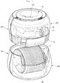
- Fig. 1 is a perspective view illustrating an outer appearance of a humidifier according to an embodiment
- Fig. 2 is an exploded perspective view of the humidifier according to an embodiment.
- an outer appearance of a humidifier 1 is defined by a case 10 having a jar shape of which an outer surface has a curved surface in a vertical direction on the whole.
- the case 10 has a preset inner space.
- the case 10 includes a front case 11 defining an outer appearance of a front portion thereof and a rear case 12 defining an outer appearance of a rear portion thereof.
- the front case 11 and the rear case 12 may be coupled to each other to define a front surface, a rear surface, and both side surfaces of the case 10.
- the front case 11 and the rear case 12 may be separably coupled to each other.
- the front case 11 includes a first upper case 13a defining an outer appearance of an upper portion thereof and a first lower case 14a defining an outer appearance of a lower portion thereof.
- the first upper case 13a and the first lower case 14a may be coupled to each other to define the front case 11.
- the first upper case 13a and the first lower case 14a may be separably coupled to each other.
- the rear case 12 includes a second upper case 13b defining an outer appearance of an upper portion thereof and a second lower case 14b defining an outer appearance of a lower portion thereof.
- the second upper case 13b and the second lower case 14b may be coupled to each other to define the rear case 12.
- the second upper case 13b and the second lower case 14b may be separably coupled to each other.
- the first upper case 13a and the second upper case 13b may be commonly called “an upper case”, and the first lower case 14a and the second lower case 14b may be commonly called “a lower case”.
- the upper case 13a and 13b and the lower case 14a and 14b may be separably coupled to each other in a vertical direction.
- a disk assembly or water tank that will be described below may be easily separated through the above-described constitutions.
- a suction hole 121 that provides a passage through which external air is introduced is defined in the rear case 12.
- the suction hole 121 may have a grill shape for filtering foreign substances contained in suctioned air.
- a suction filter (not shown) for filtering foreign substances contained in air that passes through the suction hole 121 and then is suctioned into the inner space of the case 10 may be mounted on the inside of the suction hole 121.
- the humidifier 1 further includes a water supply assembly 70 disposed on an upper portion of the case 10 to supply water and a base 20 disposed on a lower portion of the case 10 to defining a lower outer appearance of the case 10.
- the base 20 defines the lower outer appearance of the humidifier 1 and is separably mounted on the case 10. The base 20 may be separated to open the lower portion of the case 10.
- a discharge hole 16 through which the humidified air is discharged is defined in the upper portion of the humidifier 1.
- the base 20 includes a circular plate with a top surface opened. Also, the base 20 may have a flat bottom surface so that the case 10 is stably supported to contact the ground when the humidifier 1 is installed.
- a base plate 21 is disposed on the opened top surface of the base 20, and a water tank 30 is disposed on the base plate 21.
- the water tank 30 is supported by an upper portion of the base plate 21.
- a central portion of the base plate 21 is recessed downward to provide a seating part 211 on which the water tank
- the seating part 211 may have a top surface having a shape corresponding to a bottom surface of the water tank 30.
- the water tank 30 may be stably supported on the seating part 211 to prevent the water tank 30 from shaken.
- a drain hole 212 through which water leaking from the water tank 30 flows into the base 20 may be defined in the base plate 21.
- the water stored in the base plate 21 may be drained into the base 20 through the drain hole 212. The user may separate the base 20 to empty the water.
- the water tank 30 may have a water storage space having a preset size and have a shape with a top surface opened. Water for humidifying air suctioned through the suction hole 121 is accommodated in the water storage space.
- the water tank 30 may be disposed at a lower portion of the inner space of the case 10 and be supported by the base 20 or the base plate 21. Due to the above-described arrangement, a weight center of the humidifier 1 may be defined at a lower portion of the case 10. Thus, in the state where the water is accommodated in the water tank 30, the humidifier 1 may be maintained in the stable state.
- a water level sensor (not shown) for detecting a level of the water accommodated in the water tank 30 may be mounted on the inside of the water tank 30.
- the water level detected by the water level sensor may be displayed through a display window so that the user confirms the water level from the outside.
- At least a portion of the rotatable disk assembly 40 may be accommodated in the water storage space of the water tank 30.
- the disk assembly 40 may rotate to supply moisture to the air suctioned through the suction hole 121.
- the water tank 30 includes a disk accommodation part 31 for accommodating the disk assembly 40.
- the disk accommodation part 31 may be recessed downward from a lower portion of the water tank 30 to accommodate a lower end of the disk assembly 40.
- the recessed shape of the disk accommodation part 31 may correspond to that of the lower end of the disk assembly 40.
- the disk accommodation part 31 may have a shape corresponding to that of the seating part 211 of the base plate 21 and be supported by the base plate 21.
- the disk assembly 40 includes a rotation shaft 41 having a preset length and a plurality of moisture disks 42 disposed in an extension direction or length direction of the rotation shaft 41 and coupled to the rotation shaft 41.
- Each of the moisture disks 42 may have a circular plate shape. Also, an unevenness or pattern on which water drops are formed may be disposed on a surface of each of the moisture disks 42.
- the rotation shaft 41 may extend to pass through a central portion of each of the plurality of moisture disks 42. Also, the plurality of moisture disks 42 may be spaced a preset distance from each other. The preset distance may provide a passage through which air passes.
- the water stored in the water tank 30 may be supplied into the flowing air.
- the flowing air may be humidified.
- the humidified air may be discharged to the outside of the case 10 through the discharge hole 16 to increase humidify in the space in which the humidifier 1 is installed.
- the disk assembly 40 further includes a driving disk 43 for providing power to the rotation shaft 41.
- the driving disk 43 may be coupled to the rotation shaft 41 and disposed adjacent to or to contact the outermost moisture disk 42 of the plurality of moisture disks 42.
- the rotation shaft 41 may pass through the plurality of moisture disks 42 and the driving disk 43 and then be coupled to provide a rotation center of each of the plurality of moisture disks 42 and the driving desk 43.
- the driving disk 43 may be provided in plurality.
- the plurality of driving disks 43 may be disposed on both sides of the plurality of moisture disks 42.
- the driving disk 43 may have a circular plate shape having a preset thickness.
- the rotation shaft 41 may pass through a central portion of the driving disk 43 and then be coupled to the driving disk 43.
- the rotation shaft 41 When the driving disk 43 rotates, the rotation shaft 41 may rotate.
- the plurality of moisture disks 42 shaft-coupled to the rotation shaft 41 may rotate.
- a gear tooth 435 is disposed on a circumferential surface or outer circumferential surface of the driving disk 43.
- the gear tooth 435 of the driving disk 43 may be interlocked with a gear tooth 445 of a driving gear 44 that is disposed on one side of the driving disk 43.
- the gear tooth 445 of the driving gear 44 may be disposed on a circumferential surface or outer circumferential surface of the driving gear 44.
- the gear tooth of the driving gear 44 may be called "a first gear tooth 445", and the gear tooth of the driving disk 43 may be called "a second gear tooth 435".
- the disk assembly 40 further includes a disk motor 45 that provides driving force for rotating the driving gear 44.
- the driving gear 44 is shaft-coupled to the disk motor 45.
- the driving gear 44 rotates.
- the first and second gear teeth 434 and 445 may be interlocked with each other to rotate the driving disk 43.
- the rotation shaft 41 and the plurality of moisture disks 42 may rotate.
- At least a portion of the plurality of moisture disks 42 may be disposed at a height or position corresponding to that of the suction hole 121. Due the above-described arrangement, the external air suctioned through the suction hole 121 may easily flow toward the plurality of moisture disks 42.
- a lower portion of the plurality of moisture disks 42 may be disposed to be sunk in the water stored in the water tank 30. Since the rotation shaft 41 rotates, the plurality of moisture disks 42 may repeatedly access to the water stored in the water tank 30 while rotating. Also, water existing on the surfaces of the moisture disks 42 may be supplied into the air introduced through the suction hole 121. In this process, the water may be naturally evaporated. Since the plurality of moisture disks 42 rotate, the evaporation of the water may be continuously performed.
- the driving gear 44 and the disk motor 45 may be disposed in the inner space of the upper case 13a and 13b, and the driving disk 43 may be disposed in the lower case 14a and 14b. While the upper case 13a and 13b and the lower case 14a and 14b are coupled to each other, the second gear tooth 435 of the driving disk 43 may be engaged with the first gear tooth 445 of the driving gear 44. Thus, the diving disk 43 and the driving gear 44 may be coupled to each other.
- a disk handle 433 to be grasped by the user may be disposed on the driving disk 43.
- the disk handle 433 may be provided by cutting at least a portion of a disk body 431 of the driving disk 43.
- the disk handle 433 will be described below in detail.
- An air guide 15 is mounted on one side of the disk assembly 40, i.e., one side of the disk assembly 40, which is adjacent to the suction hole 121.
- the air guide 15 may guide the air suctioned through the suction hole 121 toward the disk assembly 40.
- the air guide 15 may have a plate shape corresponding to that of the suction hole 121.
- An inner case 50 is disposed above the disk assembly 40.
- the inner case 50 accommodates a fan motor assembly 60 and guides an air flow.
- the inner case 50 may guide the water supplied from the upper portion of the case 10 into the inner space of the water tank 30.
- the inner case 50 includes a first inner case 51 for guiding a flow of the supplied water and a second case 53 for guiding a flow of the air passing through the disk assembly 40.
- the flow of the supplied water and the flow of the humidified air may be guided by the first and second cases 51 and 62, respectively.
- Each of the first and second inner cases 51 and 53 may have a cylindrical shape having an empty inner space. Also, the first inner case 51 has a diameter greater than that of the second inner case 53. The second inner case 53 is disposed inside the first inner case 51.
- the fan motor assembly 60 is disposed inside the second inner case 53.
- the fan motor assembly 60 includes a fan motor 61 for generating rotation power by the applied power and a blowing fan 62 shaft-coupled to a rotation shaft of the fan motor 61.
- the blowing fan 62 may rotate to allow the external air of the case 10 to be suctioned into the inner space of the case 10. That is, the blowing fan 62 may rotate to provide suction force to the inner space of the case 10. Thus, the external air of the case 10 may be suctioned into the inner space of the case 10 through the suction hole 121 by the suction force.
- the blowing fan 62 may include a centrifugal fan.
- the blowing fan 62 may suction air in an axial direction while rotating to discharge the suctioned air in a circumferential direction. Due to the blowing fan 62, the air discharged in the circumferential direction may flow upward along an inner surface of the second inner case 53.
- the current embodiment is not limited to a kind of blowing fan 62.
- a water supply assembly 70 is disposed above the fan motor assembly 60.
- the water supply assembly 70 includes a water supply guide 71 disposed above the fan motor assembly 60 and a guide cover 72 mounted on a top surface of the water supply guide 71.
- a space part in which the supplied water flows may be defined in each of the water supply guide 71 and the guide cover 72.
- the water of the space part may flow to the inside of the first inner case 51 through a discharge part 71b.
- the discharge part 71b is disposed on an end of a discharge port 71a.
- the discharge port 71a may be provided by coupling the water supply guide 71 to the guide cover 72.
- the discharge port 71a may extend outward from a central portion of the water supply assembly 70.
- the discharge part 71b may be disposed at a position corresponding to the inner circumferential surface of the first inner case 51. Thus, the supplied water may not flow into the second inner case 53, but flow into the first inner case 51.
- the water supply assembly 70 includes a water supply case 73 disposed above the guide cover 72.
- the water supply hole 731 may be defined in an approximately central portion of the water supply case 73.
- the humidifier 1 further includes a display part 80 for displaying an operation state of the humidifier 1.
- the display part 80 includes an input device for manipulating an operation of the humidifier 1.
- the display part 80 may include a plurality of control components such as a PCB for controlling the operation of the humidifier 1.
- the input device may include a touch screen on which user's manipulation is inputted by using a sensor for detecting whether capacity changes or whether user contact occurs.
- the input device may include a button.
- the display part 80 may be disposed inside the water supply case 73 or at one position between the water supply case 73 and the guide cover 72.
- An outer appearance of the top surface of the case 10 may be defined by a top surface of the water supply assembly 70. At least a portion of the water supply case 73 may be formed of a transparent material. Thus, information displayed on the display part 80 may be easily recognized and manipulated.
- Fig. 3 is a projection coupling perspective view of the humidifier according to an embodiment
- Fig. 4 is a perspective view illustrating a state in which the upper case of the humidifier is separated according to an embodiment.
- the case 10 may be separated into the upper case 13a and 13b and the lower case 14a and 14b.
- the fan motor assembly 60, the water supply assembly 70, the driving gear 44, and the disk motor 45 may be disposed in the inner space of the upper case 13a and 13b.
- the base plate 21, the water tank 30, and a plurality of components of the display assembly 40 except for the driving gear 44 and the disk motor 45 may be disposed in the inner space of the lower case 14a and 14b. That is, the driving gear 44 and the disk motor 45 of the disk assembly 40 may be accommodated in the upper case 13a and 13b, and the rotation shaft 41, the plurality of moisture disks 42, and the driving disk 43 may be accommodated in the lower case 14a and 14b.
- a portion of the disk assembly 40, which is disposed in the inner space of the upper case 13a and 13b, may be defined as an upper assembly B
- a portion of the disk assembly 40, which is disposed in the inner space of the lower case 14a and 14b may be defined as a lower assembly A.
- the whole portion of the disk assembly 40 may be disposed in the inner space of the lower case 14.
- the disk assembly 40 may be partially divided and separately disposed.
- the second gear tooth 435 of the driving disk 43 may be engaged with the first gear tooth 445 of the driving gear 44.
- the driving disk 43 includes a disk body 431 including a shaft coupling part (see reference numeral 436 of Fig. 5 ) having an approximately circular plate shape and coupled to the rotation shaft 41 and a plurality of second gear teeth 435 disposed on an outer circumferential surface of the disk body 431.
- the driving disk 43 further includes a rotation shaft cover 432 that extends outward from an approximately central portion of the disk body 431.
- the rotation shaft cover 432 has an approximately cylindrical shape having a hollow to cover both sides of the rotation shaft 41.
- the rotation shaft cover 432 may be disposed at a rotational central portion of the driving disk 43.
- the shaft coupling part 436 may be recessed from one surface of the disk body 431, and the rotation shaft cover 432 may extend outward from the other surface of the disk body 431.
- a cover handle 412 to be grasped by the user may be disposed on the rotation shaft cover 432.
- the cover handle 412 may be disposed inside the rotation shaft cover 411.
- a rotation shaft support 141 for supporting the rotation shaft cover 432 is disposed on a side surface of the water tank 30.
- the rotation shaft support 141 may be recessed downward from an upper end of the side surface of the water tank 30.
- the rotation shaft support 141 may have a shape so that a central portion of the side surface of the water tank 30 is recessed in an approximately "U" shape when viewed from one side.
- the disk assembly 40 When the rotation shaft cover 432 is placed on the rotation shaft support 141, the disk assembly 40 may be supported by the water tank 30. As the rotation shaft 41 rotates, the rotation shaft cover 432 may rotate in the state where the rotation shaft cover 432 is supported by the rotation shaft support 141. A friction reduction member for reducing friction with the rotating rotation shaft cover 432 may be disposed on the rotation shaft support 141.
- the lower assembly A mounted on the lower case 14a and 14b may be symmetrically disposed with respect to a center of the rotation shaft 41.
- the plurality of moisture disks 42 may be coupled to the central portion of the rotation shaft 41
- the driving disk 43 may be coupled to both sides of the rotation shaft 41.
- the plurality of moisture disks 42 and the driving disk 43 may be symmetrically disposed with respect the center in the longitudinal direction of the rotation shaft 41.
- the lower assembly A has the symmetrical shape, when the lower assembly A is mounted on the lower case 14a and 14b, the lower assembly may be easily mounted in any left or right direction.
- Fig. 5 is a perspective view illustrating the lower assembly of the humidifier according to an embodiment
- Fig. 6 is an exploded perspective view illustrating the lower assembly of the humidifier according to an embodiment.
- the disk handle 433 to be grasped by the user is disposed on the driving disk 43.
- the disk handle 433 may be provided by cutting at least a portion of the disk body 431.
- the cut shape of the disk handle 431 may have an arc shape having a predetermined curvature radius.
- the disk handle 433 may be provided in plurality.
- the plurality of disk handles 433 may be disposed on both sides of the rotation shaft 41 or the rotation shaft cover 432. Due to the above-described constitutions, the user may easily grasp the plurality of disk handles 433.
- the plurality of disk handles 433 may have a shape that is symmetrical to the rotation shaft 41 or the rotation shaft cover 432.
- the upper disk handle 433 of the plurality of disk handles 433 may have an approximately " ⁇ " shape
- the lower disk handle 433 may have an approximately " ⁇ " shape with respect to the rotation shaft cover 432.
- the disk handle 431 is disposed vertically symmetrical to the rotation shaft 41 or the rotation shaft cover 432, the user may easily grasp the disk handle 431.
- At least a portion of the lower assembly A may be mounted to be accommodated in the water tank 30, and the rotation shaft 41 may extend to cross the water tank 30 from one side to the other side of the water tank 30. Both sides of the lower assembly A, i.e., the two rotation shaft cover 432 may be supported by the rotation shaft support 141 of the water tank 30.
- the rotation shaft 41 extends in a transverse or horizontal direction, and left and right portions of the lower assembly A may be symmetrical to each other in a longitudinal direction of the rotation shaft 41. That is, the lower assembly A is symmetrically disposed with respect to a central portion thereof, i.e., is symmetrical in a horizontal direction with respect to the center in the longitudinal direction of the rotation shaft 41.
- the lower assembly A is symmetrical in the horizontal direction with respect to the central portion in the longitudinal direction of the rotation shaft 41, when the user locates the lower assembly 30 inside the water tank 30, a cumbersome for matching the lower assembly A in the horizontal direction may be prevented. As a result, since the user mounts the lower assembly A in all directions, the use convenience may be improved.
- the lower assembly A when a direction in which the lower assembly A is mounted on the water tank 30 is defined as a vertical direction, and an extension direction of the rotation shaft 41 is defined as a horizontal direction, the lower assembly A may be symmetrical in the horizontal direction with respect to a virtual line that bisectionally divides the lower assembly A in the horizontal direction, i.e., an X line. Also, the lower assembly A may be symmetrical in the vertical direction with respect to a virtual line that bisectionally divides the lower assembly A in the vertical direction, i.e., a Y line.
- the lower assembly A may be symmetrical in the horizontal direction and vertical direction with respect to the central portion in the longitudinal direction or vertical direction of the rotation shaft 41.
- the lower assembly A may be mounted in the inner space of the water tank 30 regardless of the directivity. That is, the lower assembly A may be mounted so that the lower assembly A is operable in any direction.
- the suction force may be generated in the inner space of the case 10.
- air is suctioned into the inner space of the case 10 through the suction hole 121 by the suction force.
- the air suctioned into the inner space of the case 10 through the suction hole 121 may be guided by the air guide 15 and then humidified while flowing between the plurality of moisture disks 12.
- the humidified air may flow upward toward the blowing fan 62.
- the air flowing into the central portion of the blowing fan 62 is discharged to an outer space of the case 10 through the discharge hole 16 defined in the top surface of the case 10.
- the user when water is filled into the water tank 30, or the disk assembly 40 is separated for cleaning the water tank 30, the user separates the upper case 13a and 13b from the lower case 14a and 14b. Then, the lower assembly A disposed in the lower case 14a and 14b is separated from the water tank 30.
- the user grasps the disk handle 433 disposed on the driving disk 43 to easily separate the lower assembly A from the water tank 30.
- the lower assembly A is mounted in the water tank 30 in the state where the user grasps the disk handle 433.
- the lower assembly A may be easily mounted in any direction.
- the user may easily grasp the lower assembly A by using the disk handle 433 without being limited to the mounting direction of the lower assembly A.
- the user When the user supports the rotation shaft cover 432 on the rotation shaft support 141 of the water tank 30 to mount the lower assembly A on the water tank 30, the user may couple the upper case 13a and 13b to the lower case 14a and 14b to form the case 10.
- the disk assembly since the disk assembly is symmetrically disposed with respect to the central portion, when the user separates the disk assembly and then mounts the disk assembly, the disk assembly may be mounted in any left or right direction.
- the disk assembly is easily mounted, the use convenience of the humidifier may be minimized, and also the disk assembly may be easily assembled.
- the humidifier may be improved in assembility and productivity.
- the assembly defect of the disk assembly may be reduced to prevent the quality defect of the product from occurring.
- the disk handle configured to be grasped by the user may be disposed on the disk assembly to allow the user to easily grasp the disk assembly. Also, when the disk assembly is assembled or detached, the damage of the disk assembly or the user's body may be prevented.
Landscapes
- Engineering & Computer Science (AREA)
- Chemical & Material Sciences (AREA)
- Combustion & Propulsion (AREA)
- Mechanical Engineering (AREA)
- General Engineering & Computer Science (AREA)
- Dispersion Chemistry (AREA)
- Air Humidification (AREA)
Description
- The present disclosure relates to a humidifier, and more particularly, to a humidification air cleaner that is capable of performing humidification and air-cleaning functions at the same time.
- Humidifiers are a kind of home appliances for discharging air containing moisture to raise humidity in indoor air. Such a humidifier may be classified into an ultrasonic humidifier that generates fine water drops by using ultrasonic vibration through a vibrator, an electric heating humidifier that heats water by using a heater or electricity to generate steam, a compound humidifier having advantages of the electric heating humidifier having superior sterilizing effects and the ultrasonic humidifier having low power consumption and less financial burdens, and a vaporizing humidifier in which air passes through a wet filter to vaporize water.
- Recently, a plurality of various functions in addition the function for adjusting humidity in a desired space are being added to the humidifier. Thus, the additional functions may be selectively used as necessary.
- Also, products such as an air washer in which a plurality of disks are rotatably disposed, water is added to air passing through the plurality of disks to discharge the air containing moisture, thereby increasing in humidify of the air, and dusts contained in the air passing therethrough are filtered by the water are being produced.
- The invention related to a disk assembly of a humidification air cleaner is disclosed in Korean Patent Registration No.
10-1006991 - According to the prior art document, a constitution having an arc shape on which an inclined rib is disposed to be inclined in a clockwise and counterclockwise direction of the disk so that water is pumped regardless of the rotation direction of the disk is provided.
- According to the constitution disclosed in the prior art document, the water pumping effect may be unchanged even though the rotation direction of the disk changes, and efficiency in precipitation and humidity amount may be maintained.
- Also, the invention related to an air cleaning humidifier and a disk assembly thereof is disclosed in Korean Patent Registration No.
10-2011-0039691 - In the disk disclosed in the prior art documents, since a handle for graphing the disk when the disk is withdrawn or inserted is not provided, it may be difficult to detach the disk.
- Also, when a user detaches the disk, user's inconvenience such as missing of the disk or jamming of user's fingers, damage of the disk, and injury of the user's body may occur.
-
KR 10-2010-0038663 A claim 1. - Embodiments provide a humidifier having improved user's convenience.
- Embodiments also provide a humidifier having improved assembility and productivity.
- In one embodiment, a humidifier includes: a case having an inner space; a fan motor assembly mounted in the inner space of the case to forcibly blow air; a disk assembly rotatably mounted in the inner space of the case, the disk assembly including a plurality of moisture disks for humidifying the suctioned air and a driving disk for rotating the moisture disks; and a disk handle disposed on the driving disk, the disk handle being grasped for movement of the disk assembly.
- The humidifier further includes: a water supply part disposed on an upper portion of the case to supply water; a first inner case disposed on one side of the disk assembly to guide a flow of the water supplied through the water supply part; and a second case disposed inside the first inner case to guide a flow of air passing through the disk assembly.
- The disk handle may be formed by cutting at least a portion of the driving disk.
- The driving disk may include a disk body having a circular plate shape and a gear tooth disposed on an outer circumferential surface of the disk body, and the disk handle is formed by cutting at least a portion of the disk body.
- The disk handle may be provided in plurality.
- The plurality of disk handles may be symmetrical with respect to a rotational central portion of the driving disk.
- The disk assembly may further include a rotation shaft coupled to the plurality of moisture disks and the driving disk to rotate.
- A rotation shaft cover for covering the rotation shaft may be disposed on the rotational central portion of the driving disk.
- The disk handle may be cut in an arc shape.
- The disk assembly may include: a driving gear including a first gear tooth interlocked with a second gear tooth of the driving disk; and a driving motor providing driving force to the driving gear.
- The driving disk may be disposed on each of both sides of the plurality of moisture disks.
- The humidifier may further include a cover handle disposed on the rotation shaft cover and grasped by a user.
- The case may include an upper case and a lower case coupled to a lower potion of the upper case, and the disk assembly may include: an upper assembly disposed in the upper case, the upper assembly including a driving motor and a driving gear; and a lower assembly disposed in the lower case, the lower assembly including the plurality of moisture disks, the driving disk, and a rotation shaft coupled to the plurality of moisture disks and the driving disk.
- When a direction in which the lower assembly (A) is mounted on the lower case is defined as a vertical direction, and a direction in which the rotation shaft extends is defined as a horizontal direction, the lower assembly (A) may be horizontally symmetrical with respect to a virtual line that bisectionally divides the lower assembly (A) in the horizontal direction.
- The lower assembly (A) may be vertically symmetrical with respect to a virtual line that bisectionally divides the lower assembly (A) in the vertical direction.
- The details of one or more embodiments are set forth in the accompanying drawings and the description below. Other features will be apparent from the description and drawings, and from the claims.
-
-
Fig. 1 is a perspective view illustrating an outer appearance of a humidifier according to an embodiment. -
Fig. 2 is an exploded perspective view of the humidifier according to an embodiment. -
Fig. 3 is a projection coupling perspective view of the humidifier according to an embodiment. -
Fig. 4 is a perspective view illustrating a state in which an upper case of the humidifier is separated according to an embodiment. -
Fig. 5 is a perspective view illustrating a lower assembly of the humidifier according to an embodiment. -
Fig. 6 is an exploded perspective view illustrating the lower assembly of the humidifier according to an embodiment. -
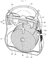
Fig. 7 is a cut-away perspective view illustrating an air flow in a humidifier according to another embodiment. - Preferred embodiments of the present disclosure will be described below in more detail with reference to the accompanying drawings. For example, a humidifier on which a disk assembly is mounted according to an embodiment will be described below.
- Note that the same or similar components in the drawings are designated by the same reference numerals as far as possible even if they are shown in different drawings. In the following description of the present disclosure, a detailed description of known functions and configurations incorporated herein will be omitted to avoid making the subject matter of the present disclosure unclear.
- In the description of the elements of the present disclosure, the terms 'first', 'second', 'A', 'B', '(a)', and '(b)' may be used. However, since the terms are used only to distinguish an element from another, the essence, sequence, and order of the elements are not limited by them. When it is described that an element is "coupled to", "engaged with", or "connected to" another element, it should be understood that the element may be directly coupled or connected to the other element but still another element may be "coupled to", "engaged with", or "connected to" the other element between them.
-
Fig. 1 is a perspective view illustrating an outer appearance of a humidifier according to an embodiment, andFig. 2 is an exploded perspective view of the humidifier according to an embodiment. - Referring to
Fig. 1 , an outer appearance of ahumidifier 1 according to an embodiment is defined by acase 10 having a jar shape of which an outer surface has a curved surface in a vertical direction on the whole. Thecase 10 has a preset inner space. - In detail, the
case 10 includes afront case 11 defining an outer appearance of a front portion thereof and arear case 12 defining an outer appearance of a rear portion thereof. Thefront case 11 and therear case 12 may be coupled to each other to define a front surface, a rear surface, and both side surfaces of thecase 10. Thefront case 11 and therear case 12 may be separably coupled to each other. - The
front case 11 includes a firstupper case 13a defining an outer appearance of an upper portion thereof and a firstlower case 14a defining an outer appearance of a lower portion thereof. The firstupper case 13a and the firstlower case 14a may be coupled to each other to define thefront case 11. The firstupper case 13a and the firstlower case 14a may be separably coupled to each other. - The
rear case 12 includes a secondupper case 13b defining an outer appearance of an upper portion thereof and a secondlower case 14b defining an outer appearance of a lower portion thereof. The secondupper case 13b and the secondlower case 14b may be coupled to each other to define therear case 12. The secondupper case 13b and the secondlower case 14b may be separably coupled to each other. - The first
upper case 13a and the secondupper case 13b may be commonly called "an upper case", and the firstlower case 14a and the secondlower case 14b may be commonly called "a lower case". - The
upper case lower case - A
suction hole 121 that provides a passage through which external air is introduced is defined in therear case 12. Thesuction hole 121 may have a grill shape for filtering foreign substances contained in suctioned air. Also, a suction filter (not shown) for filtering foreign substances contained in air that passes through thesuction hole 121 and then is suctioned into the inner space of thecase 10 may be mounted on the inside of thesuction hole 121. - The
humidifier 1 further includes awater supply assembly 70 disposed on an upper portion of thecase 10 to supply water and a base 20 disposed on a lower portion of thecase 10 to defining a lower outer appearance of thecase 10. - The
base 20 defines the lower outer appearance of thehumidifier 1 and is separably mounted on thecase 10. The base 20 may be separated to open the lower portion of thecase 10. - A
discharge hole 16 through which the humidified air is discharged is defined in the upper portion of thehumidifier 1. - Referring to
FIG. 2 , thebase 20 includes a circular plate with a top surface opened. Also, thebase 20 may have a flat bottom surface so that thecase 10 is stably supported to contact the ground when thehumidifier 1 is installed. - A
base plate 21 is disposed on the opened top surface of thebase 20, and awater tank 30 is disposed on thebase plate 21. Thewater tank 30 is supported by an upper portion of thebase plate 21. - A central portion of the
base plate 21 is recessed downward to provide aseating part 211 on which the water tank - 30 is seated. The
seating part 211 may have a top surface having a shape corresponding to a bottom surface of thewater tank 30. Thus, thewater tank 30 may be stably supported on theseating part 211 to prevent thewater tank 30 from shaken. - A
drain hole 212 through which water leaking from thewater tank 30 flows into the base 20 may be defined in thebase plate 21. When the water overflows by the movement of thehumidifier 1 or the detachment of thewater tank 30, the water stored in thebase plate 21 may be drained into the base 20 through thedrain hole 212. The user may separate the base 20 to empty the water. - The
water tank 30 may have a water storage space having a preset size and have a shape with a top surface opened. Water for humidifying air suctioned through thesuction hole 121 is accommodated in the water storage space. - The
water tank 30 may be disposed at a lower portion of the inner space of thecase 10 and be supported by the base 20 or thebase plate 21. Due to the above-described arrangement, a weight center of thehumidifier 1 may be defined at a lower portion of thecase 10. Thus, in the state where the water is accommodated in thewater tank 30, thehumidifier 1 may be maintained in the stable state. - A water level sensor (not shown) for detecting a level of the water accommodated in the
water tank 30 may be mounted on the inside of thewater tank 30. Here, the water level detected by the water level sensor may be displayed through a display window so that the user confirms the water level from the outside. - At least a portion of the
rotatable disk assembly 40 may be accommodated in the water storage space of thewater tank 30. Thedisk assembly 40 may rotate to supply moisture to the air suctioned through thesuction hole 121. - The
water tank 30 includes adisk accommodation part 31 for accommodating thedisk assembly 40. Thedisk accommodation part 31 may be recessed downward from a lower portion of thewater tank 30 to accommodate a lower end of thedisk assembly 40. The recessed shape of thedisk accommodation part 31 may correspond to that of the lower end of thedisk assembly 40. - The
disk accommodation part 31 may have a shape corresponding to that of theseating part 211 of thebase plate 21 and be supported by thebase plate 21. - The
disk assembly 40 includes arotation shaft 41 having a preset length and a plurality ofmoisture disks 42 disposed in an extension direction or length direction of therotation shaft 41 and coupled to therotation shaft 41. Each of themoisture disks 42 may have a circular plate shape. Also, an unevenness or pattern on which water drops are formed may be disposed on a surface of each of themoisture disks 42. - The
rotation shaft 41 may extend to pass through a central portion of each of the plurality ofmoisture disks 42. Also, the plurality ofmoisture disks 42 may be spaced a preset distance from each other. The preset distance may provide a passage through which air passes. - When the plurality of
moisture disks 42 rotate by therotation shaft 41, the water stored in thewater tank 30 may be supplied into the flowing air. In this process, the flowing air may be humidified. The humidified air may be discharged to the outside of thecase 10 through thedischarge hole 16 to increase humidify in the space in which thehumidifier 1 is installed. - The
disk assembly 40 further includes adriving disk 43 for providing power to therotation shaft 41. For example, thedriving disk 43 may be coupled to therotation shaft 41 and disposed adjacent to or to contact theoutermost moisture disk 42 of the plurality ofmoisture disks 42. - The
rotation shaft 41 may pass through the plurality ofmoisture disks 42 and thedriving disk 43 and then be coupled to provide a rotation center of each of the plurality ofmoisture disks 42 and the drivingdesk 43. - Also, the
driving disk 43 may be provided in plurality. The plurality of drivingdisks 43 may be disposed on both sides of the plurality ofmoisture disks 42. Thedriving disk 43 may have a circular plate shape having a preset thickness. Therotation shaft 41 may pass through a central portion of thedriving disk 43 and then be coupled to thedriving disk 43. - When the
driving disk 43 rotates, therotation shaft 41 may rotate. Thus, the plurality ofmoisture disks 42 shaft-coupled to therotation shaft 41 may rotate. - A
gear tooth 435 is disposed on a circumferential surface or outer circumferential surface of thedriving disk 43. Thegear tooth 435 of thedriving disk 43 may be interlocked with agear tooth 445 of adriving gear 44 that is disposed on one side of thedriving disk 43. Thegear tooth 445 of thedriving gear 44 may be disposed on a circumferential surface or outer circumferential surface of thedriving gear 44. The gear tooth of thedriving gear 44 may be called "afirst gear tooth 445", and the gear tooth of thedriving disk 43 may be called "asecond gear tooth 435". - The
disk assembly 40 further includes adisk motor 45 that provides driving force for rotating thedriving gear 44. Thedriving gear 44 is shaft-coupled to thedisk motor 45. When thedisk motor 45 is driven, thedriving gear 44 rotates. Thus, the first andsecond gear teeth driving disk 43. Also, since thedriving disk 43 rotates, therotation shaft 41 and the plurality ofmoisture disks 42 may rotate. - At least a portion of the plurality of
moisture disks 42 may be disposed at a height or position corresponding to that of thesuction hole 121. Due the above-described arrangement, the external air suctioned through thesuction hole 121 may easily flow toward the plurality ofmoisture disks 42. - A lower portion of the plurality of
moisture disks 42 may be disposed to be sunk in the water stored in thewater tank 30. Since therotation shaft 41 rotates, the plurality ofmoisture disks 42 may repeatedly access to the water stored in thewater tank 30 while rotating. Also, water existing on the surfaces of themoisture disks 42 may be supplied into the air introduced through thesuction hole 121. In this process, the water may be naturally evaporated. Since the plurality ofmoisture disks 42 rotate, the evaporation of the water may be continuously performed. - The
driving gear 44 and thedisk motor 45 may be disposed in the inner space of theupper case driving disk 43 may be disposed in thelower case upper case lower case second gear tooth 435 of thedriving disk 43 may be engaged with thefirst gear tooth 445 of thedriving gear 44. Thus, thediving disk 43 and thedriving gear 44 may be coupled to each other. - A disk handle 433 to be grasped by the user may be disposed on the
driving disk 43. The disk handle 433 may be provided by cutting at least a portion of adisk body 431 of thedriving disk 43. The disk handle 433 will be described below in detail. - An
air guide 15 is mounted on one side of thedisk assembly 40, i.e., one side of thedisk assembly 40, which is adjacent to thesuction hole 121. Theair guide 15 may guide the air suctioned through thesuction hole 121 toward thedisk assembly 40. Theair guide 15 may have a plate shape corresponding to that of thesuction hole 121. - An
inner case 50 is disposed above thedisk assembly 40. Theinner case 50 accommodates afan motor assembly 60 and guides an air flow. In addition, theinner case 50 may guide the water supplied from the upper portion of thecase 10 into the inner space of thewater tank 30. - In detail, the
inner case 50 includes a firstinner case 51 for guiding a flow of the supplied water and asecond case 53 for guiding a flow of the air passing through thedisk assembly 40. The flow of the supplied water and the flow of the humidified air may be guided by the first andsecond cases - Each of the first and second
inner cases inner case 51 has a diameter greater than that of the secondinner case 53. The secondinner case 53 is disposed inside the firstinner case 51. - The
fan motor assembly 60 is disposed inside the secondinner case 53. Thefan motor assembly 60 includes afan motor 61 for generating rotation power by the applied power and a blowingfan 62 shaft-coupled to a rotation shaft of thefan motor 61. - The blowing
fan 62 may rotate to allow the external air of thecase 10 to be suctioned into the inner space of thecase 10. That is, the blowingfan 62 may rotate to provide suction force to the inner space of thecase 10. Thus, the external air of thecase 10 may be suctioned into the inner space of thecase 10 through thesuction hole 121 by the suction force. - For example, the blowing
fan 62 may include a centrifugal fan. The blowingfan 62 may suction air in an axial direction while rotating to discharge the suctioned air in a circumferential direction. Due to the blowingfan 62, the air discharged in the circumferential direction may flow upward along an inner surface of the secondinner case 53. However, the current embodiment is not limited to a kind of blowingfan 62. - A
water supply assembly 70 is disposed above thefan motor assembly 60. Thewater supply assembly 70 includes awater supply guide 71 disposed above thefan motor assembly 60 and aguide cover 72 mounted on a top surface of thewater supply guide 71. - A space part in which the supplied water flows may be defined in each of the
water supply guide 71 and theguide cover 72. The water of the space part may flow to the inside of the firstinner case 51 through adischarge part 71b. Thedischarge part 71b is disposed on an end of adischarge port 71a. - The
discharge port 71a may be provided by coupling thewater supply guide 71 to theguide cover 72. Thedischarge port 71a may extend outward from a central portion of thewater supply assembly 70. Thedischarge part 71b may be disposed at a position corresponding to the inner circumferential surface of the firstinner case 51. Thus, the supplied water may not flow into the secondinner case 53, but flow into the firstinner case 51. - The
water supply assembly 70 includes awater supply case 73 disposed above theguide cover 72. Thewater supply hole 731 may be defined in an approximately central portion of thewater supply case 73. - The
humidifier 1 further includes adisplay part 80 for displaying an operation state of thehumidifier 1. Thedisplay part 80 includes an input device for manipulating an operation of thehumidifier 1. Thedisplay part 80 may include a plurality of control components such as a PCB for controlling the operation of thehumidifier 1. - The input device may include a touch screen on which user's manipulation is inputted by using a sensor for detecting whether capacity changes or whether user contact occurs. For another example, the input device may include a button.
- The
display part 80 may be disposed inside thewater supply case 73 or at one position between thewater supply case 73 and theguide cover 72. - An outer appearance of the top surface of the
case 10 may be defined by a top surface of thewater supply assembly 70. At least a portion of thewater supply case 73 may be formed of a transparent material. Thus, information displayed on thedisplay part 80 may be easily recognized and manipulated. -
Fig. 3 is a projection coupling perspective view of the humidifier according to an embodiment, andFig. 4 is a perspective view illustrating a state in which the upper case of the humidifier is separated according to an embodiment. - Referring to
Figs. 3 and4 , thecase 10 may be separated into theupper case lower case - The
fan motor assembly 60, thewater supply assembly 70, thedriving gear 44, and thedisk motor 45 may be disposed in the inner space of theupper case - The
base plate 21, thewater tank 30, and a plurality of components of thedisplay assembly 40 except for thedriving gear 44 and thedisk motor 45 may be disposed in the inner space of thelower case driving gear 44 and thedisk motor 45 of thedisk assembly 40 may be accommodated in theupper case rotation shaft 41, the plurality ofmoisture disks 42, and thedriving disk 43 may be accommodated in thelower case - A portion of the
disk assembly 40, which is disposed in the inner space of theupper case disk assembly 40, which is disposed in the inner space of thelower case disk assembly 40 may be disposed in the inner space of the lower case 14. However, to effectively utilize the inner space of thecase 10, thedisk assembly 40 may be partially divided and separately disposed. - In the state where the upper assembly B is disposed in the inner space of the
upper case lower case lower case upper case second gear tooth 435 of thedriving disk 43 may be engaged with thefirst gear tooth 445 of thedriving gear 44. - The user grasps the disk handle 433 disposed on the
driving disk 43 to easily locate the lower assembly A into thewater tank 30. - The
driving disk 43 includes adisk body 431 including a shaft coupling part (seereference numeral 436 ofFig. 5 ) having an approximately circular plate shape and coupled to therotation shaft 41 and a plurality ofsecond gear teeth 435 disposed on an outer circumferential surface of thedisk body 431. - The
driving disk 43 further includes arotation shaft cover 432 that extends outward from an approximately central portion of thedisk body 431. Therotation shaft cover 432 has an approximately cylindrical shape having a hollow to cover both sides of therotation shaft 41. Therotation shaft cover 432 may be disposed at a rotational central portion of thedriving disk 43. - The
shaft coupling part 436 may be recessed from one surface of thedisk body 431, and therotation shaft cover 432 may extend outward from the other surface of thedisk body 431. - Also, a cover handle 412 to be grasped by the user may be disposed on the
rotation shaft cover 432. The cover handle 412 may be disposed inside the rotation shaft cover 411. - A
rotation shaft support 141 for supporting therotation shaft cover 432 is disposed on a side surface of thewater tank 30. Therotation shaft support 141 may be recessed downward from an upper end of the side surface of thewater tank 30. For example, therotation shaft support 141 may have a shape so that a central portion of the side surface of thewater tank 30 is recessed in an approximately "U" shape when viewed from one side. - When the
rotation shaft cover 432 is placed on therotation shaft support 141, thedisk assembly 40 may be supported by thewater tank 30. As therotation shaft 41 rotates, therotation shaft cover 432 may rotate in the state where therotation shaft cover 432 is supported by therotation shaft support 141. A friction reduction member for reducing friction with the rotatingrotation shaft cover 432 may be disposed on therotation shaft support 141. - The lower assembly A mounted on the
lower case rotation shaft 41. In detail, the plurality ofmoisture disks 42 may be coupled to the central portion of therotation shaft 41, and thedriving disk 43 may be coupled to both sides of therotation shaft 41. Thus, the plurality ofmoisture disks 42 and thedriving disk 43 may be symmetrically disposed with respect the center in the longitudinal direction of therotation shaft 41. - Thus, since the lower assembly A has the symmetrical shape, when the lower assembly A is mounted on the
lower case -
Fig. 5 is a perspective view illustrating the lower assembly of the humidifier according to an embodiment, andFig. 6 is an exploded perspective view illustrating the lower assembly of the humidifier according to an embodiment. - Referring to
Figs. 5 and6 , the disk handle 433 to be grasped by the user is disposed on thedriving disk 43. The disk handle 433 may be provided by cutting at least a portion of thedisk body 431. The cut shape of the disk handle 431 may have an arc shape having a predetermined curvature radius. - The disk handle 433 may be provided in plurality. The plurality of disk handles 433 may be disposed on both sides of the
rotation shaft 41 or therotation shaft cover 432. Due to the above-described constitutions, the user may easily grasp the plurality of disk handles 433. - The plurality of disk handles 433 may have a shape that is symmetrical to the
rotation shaft 41 or therotation shaft cover 432. For example, the upper disk handle 433 of the plurality of disk handles 433 may have an approximately " ∩ " shape, and thelower disk handle 433 may have an approximately " ∪ " shape with respect to therotation shaft cover 432. - As described above, since the
disk handle 431 is disposed vertically symmetrical to therotation shaft 41 or therotation shaft cover 432, the user may easily grasp thedisk handle 431. - At least a portion of the lower assembly A may be mounted to be accommodated in the
water tank 30, and therotation shaft 41 may extend to cross thewater tank 30 from one side to the other side of thewater tank 30. Both sides of the lower assembly A, i.e., the tworotation shaft cover 432 may be supported by therotation shaft support 141 of thewater tank 30. - The
rotation shaft 41 extends in a transverse or horizontal direction, and left and right portions of the lower assembly A may be symmetrical to each other in a longitudinal direction of therotation shaft 41. That is, the lower assembly A is symmetrically disposed with respect to a central portion thereof, i.e., is symmetrical in a horizontal direction with respect to the center in the longitudinal direction of therotation shaft 41. - As described above, since the lower assembly A is symmetrical in the horizontal direction with respect to the central portion in the longitudinal direction of the
rotation shaft 41, when the user locates thelower assembly 30 inside thewater tank 30, a cumbersome for matching the lower assembly A in the horizontal direction may be prevented. As a result, since the user mounts the lower assembly A in all directions, the use convenience may be improved. - Referring to
Fig. 6 , when a direction in which the lower assembly A is mounted on thewater tank 30 is defined as a vertical direction, and an extension direction of therotation shaft 41 is defined as a horizontal direction, the lower assembly A may be symmetrical in the horizontal direction with respect to a virtual line that bisectionally divides the lower assembly A in the horizontal direction, i.e., an X line. Also, the lower assembly A may be symmetrical in the vertical direction with respect to a virtual line that bisectionally divides the lower assembly A in the vertical direction, i.e., a Y line. - In summary, the lower assembly A may be symmetrical in the horizontal direction and vertical direction with respect to the central portion in the longitudinal direction or vertical direction of the
rotation shaft 41. Thus, when the user grasps the disk handle 433 to mount the lower assembly A in the inner space of thewater tank 30, the lower assembly A may be mounted in the inner space of thewater tank 30 regardless of the directivity. That is, the lower assembly A may be mounted so that the lower assembly A is operable in any direction. - Hereinafter, an operation of the humidifier according to an embodiment will be described with reference to
Fig. 7 . - First, when the user connects a power source to the
case 10, power is applied to the plurality of components mounted in the inner space of thecase 10. Here, while the power is applied to thefan motor assembly 60, the blowingfan 62 rotates. - Since the blowing
fan 62 rotates, the suction force may be generated in the inner space of thecase 10. Thus, air is suctioned into the inner space of thecase 10 through thesuction hole 121 by the suction force. - The air suctioned into the inner space of the
case 10 through thesuction hole 121 may be guided by theair guide 15 and then humidified while flowing between the plurality ofmoisture disks 12. The humidified air may flow upward toward the blowingfan 62. - The air flowing into the central portion of the blowing
fan 62 is discharged to an outer space of thecase 10 through thedischarge hole 16 defined in the top surface of thecase 10. - Also, when water is filled into the
water tank 30, or thedisk assembly 40 is separated for cleaning thewater tank 30, the user separates theupper case lower case lower case water tank 30. - Here, the user grasps the disk handle 433 disposed on the
driving disk 43 to easily separate the lower assembly A from thewater tank 30. - After the user fills the water in the
water tank 30, or the cleaning of the water tank is completed, the lower assembly A is mounted in thewater tank 30 in the state where the user grasps thedisk handle 433. - Here, sine the lower assembly A is symmetrical in the vertical direction with respect to the
rotation shaft 41 and in the horizontal direction with respect to the central portion in the longitudinal direction of therotation shaft 41, the lower assembly A may be easily mounted in any direction. - That is, the user may easily grasp the lower assembly A by using the disk handle 433 without being limited to the mounting direction of the lower assembly A.
- When the user supports the
rotation shaft cover 432 on therotation shaft support 141 of thewater tank 30 to mount the lower assembly A on thewater tank 30, the user may couple theupper case lower case case 10. - In the humidifier according to the embodiments, since the disk assembly is symmetrically disposed with respect to the central portion, when the user separates the disk assembly and then mounts the disk assembly, the disk assembly may be mounted in any left or right direction.
- As described above, since the disk assembly is easily mounted, the use convenience of the humidifier may be minimized, and also the disk assembly may be easily assembled.
- Since the disk assembly is easily assembled, the humidifier may be improved in assembility and productivity.
- Also, the assembly defect of the disk assembly may be reduced to prevent the quality defect of the product from occurring.
- Also, the disk handle configured to be grasped by the user may be disposed on the disk assembly to allow the user to easily grasp the disk assembly. Also, when the disk assembly is assembled or detached, the damage of the disk assembly or the user's body may be prevented.
- Although embodiments have been described with reference to a number of illustrative embodiments thereof, it should be understood that numerous other modifications and embodiments can be devised by those skilled in the art that will fall within the scope of the principles of this disclosure. More particularly, various variations and modifications are possible in the component parts and/or arrangements of the subject combination arrangement within the scope of the disclosure, the drawings and the appended claims. In addition to variations and modifications in the component parts and/or arrangements, alternative uses will also be apparent to those skilled in the art.
Claims (14)
- A humidifier (1) comprising:a case (10) having an inner space;a fan motor assembly (60) mounted in the inner space of the case (10) to blow air;a disk assembly (40) rotatably mounted in the inner space of the case (10), the disk assembly (40) comprising a plurality of moisture disks (42) for humidifying suctioned air and a driving disk (43) for rotating the moisture disks (42); anda disk handle (433) disposed on the driving disk (43), the disk handle (433) being graspeable by a user for movement of the disk assembly (40);characterized by a water supply part (70) disposed on an upper portion of the case (10) to supply water;a first inner case (51) disposed on one side of the disk assembly (40) to guide a flow of the water supplied through the water supply part (70); anda second case (53) disposed inside the first inner case (51) to guide a flow of air passing through the disk assembly (40).
- The humidifier according to claim 1, wherein the disk handle (433) is formed by cutting at least a portion of the driving disk (43).
- The humidifier according to claim 1, wherein the driving disk (43) comprises a disk body (431) having a circular plate shape and a gear tooth (435) disposed on an outer circumferential surface of the disk body, and
the disk handle (433) is formed by cutting at least a portion of the disk body (431). - The humidifier according to claim 2, wherein the disk handle (433) is provided in plurality.
- The humidifier according to claim 4, wherein the plurality of disk handles (433) are arranged symmetrical with respect to a rotational central portion of the driving disk (433) .
- The humidifier according to any one of claims 1 to 5, wherein the disk assembly (40) further comprises a rotation shaft (41) coupled to the plurality of moisture disks (42) and the driving disk (43) to rotate.
- The humidifier according to claim 6, wherein a rotation shaft cover (432) for covering the rotation shaft (41) is disposed on the rotational central portion of the driving disk (43).
- The humidifier according to any one of claims claim 2 to 7, wherein the disk handle (433) has an arc shape.
- The humidifier according to any one of claims 1 to 8, wherein the disk assembly (40) comprises:a driving gear (44) comprising a first gear tooth (445) interlocked with a second gear tooth (435) of the driving disk (43); anda driving motor (45) providing driving force to the driving gear (44).
- The humidifier according to any one of claims 1 to 9, wherein the driving disk (43) is disposed on each of both sides of the plurality of moisture disks (42).
- The humidifier according to claim 7, further comprising a cover handle (412) disposed on the rotation shaft cover (432) and being graspeable by a user.
- The humidifier according to any one of claims 1 to 11, wherein the case (10) comprises an upper case (13a, 13b) and a lower case (14a, 14b) coupled to a lower portion of the upper case, and
the disk assembly (40) comprises:an upper assembly (B) disposed in the upper case (13a, 13b), the upper assembly comprising a driving motor (45) and a driving gear; anda lower assembly (A) disposed in the lower case (14a, 14b), the lower assembly (A) comprising the plurality of moisture disks (42), the driving disk (43), and a rotation shaft (41) coupled to the plurality of moisture disks (42) and the driving disk (43). - The humidifier according to claim 12, wherein, when a direction in which the lower assembly (A) is mounted on the lower case (14a, 14b) is defined as a vertical direction, and a direction in which the rotation shaft (41) extends is defined as a horizontal direction, the lower assembly (A) is horizontally symmetrical with respect to a virtual line that bisectionally divides the lower assembly (A) in the horizontal direction.
- The humidifier according to claim 13, wherein the lower assembly (A) is vertically symmetrical with respect to a virtual line that bisectionally divides the lower assembly (A) in the vertical direction.
Applications Claiming Priority (1)
| Application Number | Priority Date | Filing Date | Title |
|---|---|---|---|
| KR1020140138861A KR101691259B1 (en) | 2014-10-15 | 2014-10-15 | Humidifier |
Publications (2)
| Publication Number | Publication Date |
|---|---|
| EP3009758A1 EP3009758A1 (en) | 2016-04-20 |
| EP3009758B1 true EP3009758B1 (en) | 2020-08-05 |
Family
ID=54249394
Family Applications (1)
| Application Number | Title | Priority Date | Filing Date |
|---|---|---|---|
| EP15187541.6A Active EP3009758B1 (en) | 2014-10-15 | 2015-09-30 | Humidifier |
Country Status (3)
| Country | Link |
|---|---|
| EP (1) | EP3009758B1 (en) |
| KR (1) | KR101691259B1 (en) |
| CN (1) | CN105526659B (en) |
Families Citing this family (12)
| Publication number | Priority date | Publication date | Assignee | Title |
|---|---|---|---|---|
| KR102275299B1 (en) * | 2014-09-03 | 2021-07-08 | 엘지전자 주식회사 | Air washer |
| KR102342407B1 (en) * | 2017-06-08 | 2021-12-24 | 엘지전자 주식회사 | Humidifier and control method thereof |
| CN108224720B (en) * | 2018-01-05 | 2020-11-20 | 温州市全越科技有限公司 | Driving device of water stirring roller of air purifier |
| CN108302051A (en) * | 2018-01-05 | 2018-07-20 | 杭州显庆科技有限公司 | A kind of fan assembly of air purifier |
| CN109539445A (en) * | 2018-12-28 | 2019-03-29 | 四川中邦模具有限公司 | Sieve mesh type evaporates the humidifier evaporative component of blade and its application |
| JP7129351B2 (en) * | 2019-01-30 | 2022-09-01 | 株式会社コロナ | mist generator |
| CN111928357B (en) * | 2020-07-20 | 2026-02-10 | 青岛海尔空调器有限总公司 | Device for humidity control |
| CN111928356A (en) * | 2020-07-20 | 2020-11-13 | 青岛海尔空调器有限总公司 | Device for humidity control |
| CN112024125B (en) * | 2020-08-17 | 2022-03-22 | 常州大学 | Vertical multistage double-drive coupling electrostatic dust collector |
| CN112539491B (en) * | 2021-01-20 | 2025-03-21 | 中邦(成都)电器有限公司 | Low power consumption and high efficiency evaporation device and method for pure humidifier |
| CN113217997B (en) * | 2021-04-14 | 2023-03-21 | 青岛海尔空调器有限总公司 | Washing purification module and air conditioner |
| KR102761954B1 (en) | 2022-12-23 | 2025-02-05 | 류이하 | Wet Ttype Air Clean Humidifier |
Family Cites Families (10)
| Publication number | Priority date | Publication date | Assignee | Title |
|---|---|---|---|---|
| CA2204199A1 (en) * | 1996-05-02 | 1997-11-02 | Rodney B. Burns | Air humidifier with reduced mineral buildup |
| CN2628922Y (en) * | 2003-07-23 | 2004-07-28 | 北京亚都科技股份有限公司 | Air humidifier |
| KR20100038661A (en) * | 2008-10-06 | 2010-04-15 | 위니아만도 주식회사 | Disk assembly of air washer |
| KR101006991B1 (en) * | 2008-10-06 | 2011-01-12 | 위니아만도 주식회사 | Disk Assembly of Humidifier Air Cleaner |
| KR101027060B1 (en) * | 2008-10-06 | 2011-04-11 | 위니아만도 주식회사 | Disk Assembly of Humidifier Air Cleaner |
| KR101178665B1 (en) * | 2009-06-01 | 2012-08-30 | 위니아만도 주식회사 | Air washer and cleaning outfit for disk of air washer and cleaning method for disk of air washerd |
| KR20110039691A (en) * | 2009-10-12 | 2011-04-20 | 삼성전자주식회사 | Air Clean Humidifiers And Disk Assemblies |
| KR101307842B1 (en) * | 2011-08-25 | 2013-09-12 | 주식회사 위닉스 | Disk assembly handle of humidifying air cleaner |
| CA2755675C (en) * | 2011-10-17 | 2018-01-02 | Braeburn Systems Llc | Improved rotary disk humidifier |
| KR20130075096A (en) * | 2011-12-27 | 2013-07-05 | 위니아만도 주식회사 | Method for automatic switching to mode according to air pollution in airwasher |
-
2014
- 2014-10-15 KR KR1020140138861A patent/KR101691259B1/en not_active Expired - Fee Related
-
2015
- 2015-09-16 CN CN201510589493.1A patent/CN105526659B/en active Active
- 2015-09-30 EP EP15187541.6A patent/EP3009758B1/en active Active
Non-Patent Citations (1)
| Title |
|---|
| None * |
Also Published As
| Publication number | Publication date |
|---|---|
| CN105526659B (en) | 2018-11-27 |
| EP3009758A1 (en) | 2016-04-20 |
| KR20160044202A (en) | 2016-04-25 |
| KR101691259B1 (en) | 2016-12-29 |
| CN105526659A (en) | 2016-04-27 |
Similar Documents
| Publication | Publication Date | Title |
|---|---|---|
| EP3009758A1 (en) | Humidifier | |
| CN104949214B (en) | Dehumidifier | |
| CN102042662B (en) | Air cleaning humidifier and disc assembly thereof | |
| US10094582B2 (en) | Apparatus for both humidification and air cleaning | |
| KR102384474B1 (en) | Evaporative humidifier | |
| EP3330625B1 (en) | Humidifier | |
| EP3832217B1 (en) | Apparatus for both humidification and air cleaning | |
| EP3163180A1 (en) | Apparatus for both humidification and air cleaning | |
| KR101588128B1 (en) | humidifier | |
| EP3163189A1 (en) | Apparatus for both humidification and air cleaning | |
| KR102346621B1 (en) | Humidifier and control method thereof | |
| JP2018532095A (en) | Humidification cleaning device | |
| JP6934595B2 (en) | Humidifying device | |
| KR20170011634A (en) | Humidifier | |
| JP5850000B2 (en) | Dehumidifier drain tank | |
| KR101876217B1 (en) | Humidifying apparatus | |
| KR20150146314A (en) | Humidifier | |
| KR20170011635A (en) | Filter apparatus of Humidifier | |
| EP4455566A1 (en) | Humidifier | |
| CN102003764A (en) | Humidification apparatus and disc assembly thereof | |
| KR101304074B1 (en) | Humidifier | |
| KR101304043B1 (en) | Humidifier | |
| KR20200086971A (en) | Humidifying Member And Humidifier Having The Same | |
| CN102410599A (en) | Humidifier | |
| KR101153691B1 (en) | A dehumidifier |
Legal Events
| Date | Code | Title | Description |
|---|---|---|---|
| PUAI | Public reference made under article 153(3) epc to a published international application that has entered the european phase |
Free format text: ORIGINAL CODE: 0009012 |
|
| 17P | Request for examination filed |
Effective date: 20151030 |
|
| AK | Designated contracting states |
Kind code of ref document: A1 Designated state(s): AL AT BE BG CH CY CZ DE DK EE ES FI FR GB GR HR HU IE IS IT LI LT LU LV MC MK MT NL NO PL PT RO RS SE SI SK SM TR |
|
| AX | Request for extension of the european patent |
Extension state: BA ME |
|
| RBV | Designated contracting states (corrected) |
Designated state(s): AL AT BE BG CH CY CZ DE DK EE ES FI FR GB GR HR HU IE IS IT LI LT LU LV MC MK MT NL NO PL PT RO RS SE SI SK SM TR |
|
| GRAP | Despatch of communication of intention to grant a patent |
Free format text: ORIGINAL CODE: EPIDOSNIGR1 |
|
| STAA | Information on the status of an ep patent application or granted ep patent |
Free format text: STATUS: GRANT OF PATENT IS INTENDED |
|
| RIC1 | Information provided on ipc code assigned before grant |
Ipc: F24F 6/06 20060101AFI20200131BHEP |
|
| INTG | Intention to grant announced |
Effective date: 20200227 |
|
| GRAS | Grant fee paid |
Free format text: ORIGINAL CODE: EPIDOSNIGR3 |
|
| GRAA | (expected) grant |
Free format text: ORIGINAL CODE: 0009210 |
|
| STAA | Information on the status of an ep patent application or granted ep patent |
Free format text: STATUS: THE PATENT HAS BEEN GRANTED |
|
| AK | Designated contracting states |
Kind code of ref document: B1 Designated state(s): AL AT BE BG CH CY CZ DE DK EE ES FI FR GB GR HR HU IE IS IT LI LT LU LV MC MK MT NL NO PL PT RO RS SE SI SK SM TR |
|
| REG | Reference to a national code |
Ref country code: GB Ref legal event code: FG4D |
|
| REG | Reference to a national code |
Ref country code: CH Ref legal event code: EP |
|
| REG | Reference to a national code |
Ref country code: AT Ref legal event code: REF Ref document number: 1299253 Country of ref document: AT Kind code of ref document: T Effective date: 20200815 |
|
| REG | Reference to a national code |
Ref country code: DE Ref legal event code: R096 Ref document number: 602015056822 Country of ref document: DE |
|
| REG | Reference to a national code |
Ref country code: IE Ref legal event code: FG4D |
|
| REG | Reference to a national code |
Ref country code: LT Ref legal event code: MG4D |
|
| REG | Reference to a national code |
Ref country code: NL Ref legal event code: MP Effective date: 20200805 |
|
| REG | Reference to a national code |
Ref country code: AT Ref legal event code: MK05 Ref document number: 1299253 Country of ref document: AT Kind code of ref document: T Effective date: 20200805 |
|
| PG25 | Lapsed in a contracting state [announced via postgrant information from national office to epo] |
Ref country code: AT Free format text: LAPSE BECAUSE OF FAILURE TO SUBMIT A TRANSLATION OF THE DESCRIPTION OR TO PAY THE FEE WITHIN THE PRESCRIBED TIME-LIMIT Effective date: 20200805 Ref country code: NO Free format text: LAPSE BECAUSE OF FAILURE TO SUBMIT A TRANSLATION OF THE DESCRIPTION OR TO PAY THE FEE WITHIN THE PRESCRIBED TIME-LIMIT Effective date: 20201105 Ref country code: LT Free format text: LAPSE BECAUSE OF FAILURE TO SUBMIT A TRANSLATION OF THE DESCRIPTION OR TO PAY THE FEE WITHIN THE PRESCRIBED TIME-LIMIT Effective date: 20200805 Ref country code: FI Free format text: LAPSE BECAUSE OF FAILURE TO SUBMIT A TRANSLATION OF THE DESCRIPTION OR TO PAY THE FEE WITHIN THE PRESCRIBED TIME-LIMIT Effective date: 20200805 Ref country code: PT Free format text: LAPSE BECAUSE OF FAILURE TO SUBMIT A TRANSLATION OF THE DESCRIPTION OR TO PAY THE FEE WITHIN THE PRESCRIBED TIME-LIMIT Effective date: 20201207 Ref country code: HR Free format text: LAPSE BECAUSE OF FAILURE TO SUBMIT A TRANSLATION OF THE DESCRIPTION OR TO PAY THE FEE WITHIN THE PRESCRIBED TIME-LIMIT Effective date: 20200805 Ref country code: SE Free format text: LAPSE BECAUSE OF FAILURE TO SUBMIT A TRANSLATION OF THE DESCRIPTION OR TO PAY THE FEE WITHIN THE PRESCRIBED TIME-LIMIT Effective date: 20200805 Ref country code: BG Free format text: LAPSE BECAUSE OF FAILURE TO SUBMIT A TRANSLATION OF THE DESCRIPTION OR TO PAY THE FEE WITHIN THE PRESCRIBED TIME-LIMIT Effective date: 20201105 Ref country code: GR Free format text: LAPSE BECAUSE OF FAILURE TO SUBMIT A TRANSLATION OF THE DESCRIPTION OR TO PAY THE FEE WITHIN THE PRESCRIBED TIME-LIMIT Effective date: 20201106 Ref country code: ES Free format text: LAPSE BECAUSE OF FAILURE TO SUBMIT A TRANSLATION OF THE DESCRIPTION OR TO PAY THE FEE WITHIN THE PRESCRIBED TIME-LIMIT Effective date: 20200805 |
|
| PG25 | Lapsed in a contracting state [announced via postgrant information from national office to epo] |
Ref country code: IS Free format text: LAPSE BECAUSE OF FAILURE TO SUBMIT A TRANSLATION OF THE DESCRIPTION OR TO PAY THE FEE WITHIN THE PRESCRIBED TIME-LIMIT Effective date: 20201205 Ref country code: LV Free format text: LAPSE BECAUSE OF FAILURE TO SUBMIT A TRANSLATION OF THE DESCRIPTION OR TO PAY THE FEE WITHIN THE PRESCRIBED TIME-LIMIT Effective date: 20200805 Ref country code: RS Free format text: LAPSE BECAUSE OF FAILURE TO SUBMIT A TRANSLATION OF THE DESCRIPTION OR TO PAY THE FEE WITHIN THE PRESCRIBED TIME-LIMIT Effective date: 20200805 Ref country code: PL Free format text: LAPSE BECAUSE OF FAILURE TO SUBMIT A TRANSLATION OF THE DESCRIPTION OR TO PAY THE FEE WITHIN THE PRESCRIBED TIME-LIMIT Effective date: 20200805 Ref country code: NL Free format text: LAPSE BECAUSE OF FAILURE TO SUBMIT A TRANSLATION OF THE DESCRIPTION OR TO PAY THE FEE WITHIN THE PRESCRIBED TIME-LIMIT Effective date: 20200805 |
|
| PG25 | Lapsed in a contracting state [announced via postgrant information from national office to epo] |
Ref country code: CZ Free format text: LAPSE BECAUSE OF FAILURE TO SUBMIT A TRANSLATION OF THE DESCRIPTION OR TO PAY THE FEE WITHIN THE PRESCRIBED TIME-LIMIT Effective date: 20200805 Ref country code: DK Free format text: LAPSE BECAUSE OF FAILURE TO SUBMIT A TRANSLATION OF THE DESCRIPTION OR TO PAY THE FEE WITHIN THE PRESCRIBED TIME-LIMIT Effective date: 20200805 Ref country code: RO Free format text: LAPSE BECAUSE OF FAILURE TO SUBMIT A TRANSLATION OF THE DESCRIPTION OR TO PAY THE FEE WITHIN THE PRESCRIBED TIME-LIMIT Effective date: 20200805 Ref country code: SM Free format text: LAPSE BECAUSE OF FAILURE TO SUBMIT A TRANSLATION OF THE DESCRIPTION OR TO PAY THE FEE WITHIN THE PRESCRIBED TIME-LIMIT Effective date: 20200805 Ref country code: EE Free format text: LAPSE BECAUSE OF FAILURE TO SUBMIT A TRANSLATION OF THE DESCRIPTION OR TO PAY THE FEE WITHIN THE PRESCRIBED TIME-LIMIT Effective date: 20200805 |
|
| REG | Reference to a national code |
Ref country code: CH Ref legal event code: PL |
|
| REG | Reference to a national code |
Ref country code: DE Ref legal event code: R097 Ref document number: 602015056822 Country of ref document: DE |
|
| PG25 | Lapsed in a contracting state [announced via postgrant information from national office to epo] |
Ref country code: AL Free format text: LAPSE BECAUSE OF FAILURE TO SUBMIT A TRANSLATION OF THE DESCRIPTION OR TO PAY THE FEE WITHIN THE PRESCRIBED TIME-LIMIT Effective date: 20200805 Ref country code: MC Free format text: LAPSE BECAUSE OF FAILURE TO SUBMIT A TRANSLATION OF THE DESCRIPTION OR TO PAY THE FEE WITHIN THE PRESCRIBED TIME-LIMIT Effective date: 20200805 |
|
| PLBE | No opposition filed within time limit |
Free format text: ORIGINAL CODE: 0009261 |
|
| STAA | Information on the status of an ep patent application or granted ep patent |
Free format text: STATUS: NO OPPOSITION FILED WITHIN TIME LIMIT |
|
| REG | Reference to a national code |
Ref country code: BE Ref legal event code: MM Effective date: 20200930 |
|
| PG25 | Lapsed in a contracting state [announced via postgrant information from national office to epo] |
Ref country code: SK Free format text: LAPSE BECAUSE OF FAILURE TO SUBMIT A TRANSLATION OF THE DESCRIPTION OR TO PAY THE FEE WITHIN THE PRESCRIBED TIME-LIMIT Effective date: 20200805 Ref country code: LU Free format text: LAPSE BECAUSE OF NON-PAYMENT OF DUE FEES Effective date: 20200930 |
|
| 26N | No opposition filed |
Effective date: 20210507 |
|
| GBPC | Gb: european patent ceased through non-payment of renewal fee |
Effective date: 20201105 |
|
| PG25 | Lapsed in a contracting state [announced via postgrant information from national office to epo] |
Ref country code: IT Free format text: LAPSE BECAUSE OF FAILURE TO SUBMIT A TRANSLATION OF THE DESCRIPTION OR TO PAY THE FEE WITHIN THE PRESCRIBED TIME-LIMIT Effective date: 20200805 Ref country code: FR Free format text: LAPSE BECAUSE OF NON-PAYMENT OF DUE FEES Effective date: 20201005 |
|
| PG25 | Lapsed in a contracting state [announced via postgrant information from national office to epo] |
Ref country code: SI Free format text: LAPSE BECAUSE OF FAILURE TO SUBMIT A TRANSLATION OF THE DESCRIPTION OR TO PAY THE FEE WITHIN THE PRESCRIBED TIME-LIMIT Effective date: 20200805 Ref country code: LI Free format text: LAPSE BECAUSE OF NON-PAYMENT OF DUE FEES Effective date: 20200930 Ref country code: IE Free format text: LAPSE BECAUSE OF NON-PAYMENT OF DUE FEES Effective date: 20200930 Ref country code: BE Free format text: LAPSE BECAUSE OF NON-PAYMENT OF DUE FEES Effective date: 20200930 Ref country code: CH Free format text: LAPSE BECAUSE OF NON-PAYMENT OF DUE FEES Effective date: 20200930 |
|
| PG25 | Lapsed in a contracting state [announced via postgrant information from national office to epo] |
Ref country code: GB Free format text: LAPSE BECAUSE OF NON-PAYMENT OF DUE FEES Effective date: 20201105 |
|
| PG25 | Lapsed in a contracting state [announced via postgrant information from national office to epo] |
Ref country code: IS Free format text: LAPSE BECAUSE OF FAILURE TO SUBMIT A TRANSLATION OF THE DESCRIPTION OR TO PAY THE FEE WITHIN THE PRESCRIBED TIME-LIMIT Effective date: 20201205 Ref country code: TR Free format text: LAPSE BECAUSE OF FAILURE TO SUBMIT A TRANSLATION OF THE DESCRIPTION OR TO PAY THE FEE WITHIN THE PRESCRIBED TIME-LIMIT Effective date: 20200805 Ref country code: MT Free format text: LAPSE BECAUSE OF FAILURE TO SUBMIT A TRANSLATION OF THE DESCRIPTION OR TO PAY THE FEE WITHIN THE PRESCRIBED TIME-LIMIT Effective date: 20200805 Ref country code: CY Free format text: LAPSE BECAUSE OF FAILURE TO SUBMIT A TRANSLATION OF THE DESCRIPTION OR TO PAY THE FEE WITHIN THE PRESCRIBED TIME-LIMIT Effective date: 20200805 |
|
| PG25 | Lapsed in a contracting state [announced via postgrant information from national office to epo] |
Ref country code: MK Free format text: LAPSE BECAUSE OF FAILURE TO SUBMIT A TRANSLATION OF THE DESCRIPTION OR TO PAY THE FEE WITHIN THE PRESCRIBED TIME-LIMIT Effective date: 20200805 |
|
| PGFP | Annual fee paid to national office [announced via postgrant information from national office to epo] |
Ref country code: DE Payment date: 20240805 Year of fee payment: 10 |