EP3009725A1 - Threaded joint for oil well pipe - Google Patents
Threaded joint for oil well pipe Download PDFInfo
- Publication number
- EP3009725A1 EP3009725A1 EP14811719.5A EP14811719A EP3009725A1 EP 3009725 A1 EP3009725 A1 EP 3009725A1 EP 14811719 A EP14811719 A EP 14811719A EP 3009725 A1 EP3009725 A1 EP 3009725A1
- Authority
- EP
- European Patent Office
- Prior art keywords
- thread
- threaded
- box
- portions
- pitch
- Prior art date
- Legal status (The legal status is an assumption and is not a legal conclusion. Google has not performed a legal analysis and makes no representation as to the accuracy of the status listed.)
- Granted
Links
Images



Classifications
-
- E—FIXED CONSTRUCTIONS
- E21—EARTH OR ROCK DRILLING; MINING
- E21B—EARTH OR ROCK DRILLING; OBTAINING OIL, GAS, WATER, SOLUBLE OR MELTABLE MATERIALS OR A SLURRY OF MINERALS FROM WELLS
- E21B17/00—Drilling rods or pipes; Flexible drill strings; Kellies; Drill collars; Sucker rods; Cables; Casings; Tubings
- E21B17/02—Couplings; joints
- E21B17/04—Couplings; joints between rod or the like and bit or between rod and rod or the like
- E21B17/042—Threaded
-
- F—MECHANICAL ENGINEERING; LIGHTING; HEATING; WEAPONS; BLASTING
- F16—ENGINEERING ELEMENTS AND UNITS; GENERAL MEASURES FOR PRODUCING AND MAINTAINING EFFECTIVE FUNCTIONING OF MACHINES OR INSTALLATIONS; THERMAL INSULATION IN GENERAL
- F16L—PIPES; JOINTS OR FITTINGS FOR PIPES; SUPPORTS FOR PIPES, CABLES OR PROTECTIVE TUBING; MEANS FOR THERMAL INSULATION IN GENERAL
- F16L15/00—Screw-threaded joints; Forms of screw-threads for such joints
- F16L15/001—Screw-threaded joints; Forms of screw-threads for such joints with conical threads
- F16L15/004—Screw-threaded joints; Forms of screw-threads for such joints with conical threads with axial sealings having at least one plastically deformable sealing surface
-
- F—MECHANICAL ENGINEERING; LIGHTING; HEATING; WEAPONS; BLASTING
- F16—ENGINEERING ELEMENTS AND UNITS; GENERAL MEASURES FOR PRODUCING AND MAINTAINING EFFECTIVE FUNCTIONING OF MACHINES OR INSTALLATIONS; THERMAL INSULATION IN GENERAL
- F16L—PIPES; JOINTS OR FITTINGS FOR PIPES; SUPPORTS FOR PIPES, CABLES OR PROTECTIVE TUBING; MEANS FOR THERMAL INSULATION IN GENERAL
- F16L15/00—Screw-threaded joints; Forms of screw-threads for such joints
- F16L15/06—Screw-threaded joints; Forms of screw-threads for such joints characterised by the shape of the screw-thread
Definitions
- the present invention relates to a threaded joint for oil country tubular goods having excellent galling resistance, and more particularly to a threaded j oint for oil country tubular goods having excellent galling resistance which is suitable for the connection of steel pipes such as an OCTG (oil country tubular goods) which include, in the same category, tubings or casings used for search and production of an oil well or a gas well in general, riser pipes or line pipes.
- steel pipes such as an OCTG (oil country tubular goods) which include, in the same category, tubings or casings used for search and production of an oil well or a gas well in general, riser pipes or line pipes.
- a threaded joint has been popularly used for connecting steel pipes used in an oil-producing industrial facility such as oil country tubular goods.
- a standard threaded joint which is stipulated in API (American Petroleum Institute) has been typically used.
- API American Petroleum Institute
- recentening of a well for crude oil or a natural gas has progressed and the number of horizontal wells and inclined wells instead of vertical wells has been increasing and hence, the drilling and production environment has become difficult.
- the number of wells developed in an extremely challenging environment such as oceans and polar regions has been increasing and hence, the performances which threaded joints have to achieve are diversified including compression resistance, bending resistance, and sealability against external pressure(external pressure resistance).
- premium joint a special threaded joint having high performances which is referred to as "premium joint” is being used has increased, and a demand for the improvement of performances of the special threaded joint has been also increased more and more.
- a premium joint is a coupling-type joint where externally-threaded members (hereinafter referred to as "pins") each of which includes a tapered thread, a seal portion (to be more specific, a metal to metal seal portion) and a shoulder portion (to be more specific, a torque shoulder portion) and is formed on a pipe end portion, and a internally-threaded member which includes tapered threads, seal portions (to be more specific, metal to metal seal portions) and shoulder portions (to be more specific, torque shoulder portions) and connects the pins to each other (hereinafter referred to as "box”) are jointed to each other.
- pins externally-threaded members
- the tapered threads are important for firmly fixing the pipe joint, the seal portions play a role of ensuring air tightness by bringing the box and the pins into metal contact at such portions, and the shoulder portions form a shoulder surfaces which play a role of stoppers during fastening of the joint.
- Fig. 4 is schematic explanatory views showing a conventional example of a premium joint for an oil country tubular goods use.
- Fig. 4 is also longitudinal cross-sectional views of a threaded joint of a circular pipe (a cross-sectional view where a pipe axis extends in the cross section).
- the threaded joint includes pins 3 and a box 1 corresponding to the pins 3.
- the pin 3 On an outer surface thereof, the pin 3 has an externally-threaded portion 7 and a nose portion (also referred to as a pin nose) 8 which is an elongated portion formed adjacent to the externally-threaded portion 7 and has no threads on a tip end side of the pin 3.
- the nose portion 8 has a seal portion (to be more specific, a metal to metal seal portion) 11 on an outer peripheral surface thereof, and a shoulder portion 12 on an end surface thereof.
- the box 1 corresponding to the pins 3 has internally-threaded portions 5, seal portions 13 and shoulder portions 14 which are portions being threadedly engaged with or brought into contact with the externally threaded portions 7, the seal portions 11 and the shoulder portions 12 of the pins 3 respectively.
- a face on an opposite side to a pin pipe end is referred to as a load flank face 30 (P being affixed to the load flank face 30 on a pin side and B being affixed to the load flank face 30 on a box side), and a face on a pin pipe end side (a box center side) is referred to as a stabbing flank face 31 (P being affixed to the stabbing flank face 31 on a pin side and B being affixed to the stabbing flank face 31 on a box side).
- the seal portion 11 is formed on a tip end portion of the pin 3, and desired seal performance can be realized by imparting an appropriate fastening torque.
- the fastening torque is influenced by a lubrication condition, a surface property and the like.
- a radial-directional seal method also referred to as a radial seal type
- a radial directional component of a seal contact pressure is relatively increased.
- the radial-seal-type threaded joint is substantially equal to the conventional threaded joint having the seal portion on the tip end portion of the pin.
- the threaded portions of the threaded joint are not uniformly threadedly engaged with each other so that a concentrated load is generated at a thread end portion in general, and galling occurs when the concentrated load is excessively large.
- the inventors of the present invention have made various studies to overcome the above-mentioned drawback, have found that a contact reaction force with a threaded portion on a pin pipe end side can be decreased by properly setting a thread pitch on a box center side so that galling can be prevented, and have arrived at the present invention based on such finding.
- the present invention has the following technical features.
- a concentrated load on the threaded potion on the pin pipe end side can be decreased so that the threaded joint for oil country tubular goods having excellent galling resistance can be acquired.
- the threaded joint according to the present invention has the substantially same constitution as the conventional premium joint exemplified in Fig. 4 with respect to the point that the threaded joint includes: pins 3 each of which occupies a pipe end portion of a steel pipe 2 for an oil country tubular goods, and includes a externally-threaded portion 7, a nose portion 8 which extends toward a pipe end side from the externally-threaded portion 7, and a shoulder portion 12 forming a distal end of the nose portion 8; and a box 1 which includes internally-threaded portions 5 each forming a threaded portion by being threadedly joined with the externally-threaded portion 7, and shoulder portions 14 which are brought into contact with the shoulder portions 12 of the pins 3, wherein the pins 3 and the box 1 are joined to each other by the threaded joining so that portions between the threaded portions 5 and 7 and the shoulder portions 12 and 14 are brought into metal-to-metal contact with each other thus
- the technical feature of the present invention lies in that, in the internally-threaded portion 5, a pitch change is made such that a internally-thread pitch 20B has the same value as an externally-thread pitch 20P from a thread end portion on a box end side to a pitch change position PCP taken on a box center side with respect to a position away from the thread end portion by 1/2 of an entire length of the threaded portion (see Fig. 1(b) ), and the internally-thread pitch 20B is changed to a value less than the externally-thread pitch 20P at the pitch change position PCP so that a thread gap 10 defined above is gradually decreased from the pitch change position PCP to a position of the thread end portion on the box center side (see Fig. 1(c) ), and the thread gap is eventually set to a value which is 0.2 to 0.8 times as large as the thread gap before the pitch change is made.
- a contact face pressure which acts on the load flank face 30P on a pin pipe end side is decreased (a face pressure decreasing effect). Accordingly, a concentrated load which acts on the load flank face 30P on a pin pipe end side at the time of fastening is dispersed so that it is possible to acquire an effect of effectively decreasing the load (referred to as a load dispersing effect).
- a short-pitched region When a length of a region in the pipe axis direction from the pitch change position PCP to an end of the internally-threaded portion 5 on a box center side (referred to as a short-pitched region) is set excessively long, there arises a difficulty that an extremely accurate pitch change becomes necessary so that the threaded joint is not suitable for industrial production. There also arises a difficulty that when the short-pitched region includes a wide region where no concentrated load exists although a contact face pressure is increased only in the vicinity of a pin pipe end side, the above-mentioned load dispersing effect becomes insufficient. In view of the above, it is necessary to set the length of the short-pitched region to less than 1/2 of the entire length of the threaded portion.
- the length of the short-pitched region is excessively short, there is a possibility that a load diffusion effect becomes insufficient so that a concentrated load is generated in the threaded portion outside the short-pitched region. Accordingly, it is preferable to set the length of the short-pitched region to a length corresponding to an amount of three ridges in terms of the number of thread ridges (an amount of three pitches in terms of the thread pitch) or more.
- Fig. 2 is graphs showing one example of the pitch change according to the present invention, wherein Fig. 2(a) is a diagram setting the relationship between the number of thread ridges which are used as indices of the distance in the pipe axis direction from a pin pipe end side and the thread gap. Fig. 2(b) is a diagram setting the relationship between the number of thread ridges and the pitch of internally-threads.
- a threaded joint which is constituted of: pins formed by applying thread cutting to end portions of a steel pipe having an outer diameter of 7-5/8" (inch) and a wall thickness of 0.625" (inch) ; and a box corresponding to the pins is used as a subject.
- the pitch change position PCP is set at the position where the number of thread ridges is 5, and the internal pitch is changed from 0.2000" (inch) to 0.1996" (inch) at this position.
- the number of thread ridges over the entire length of the threaded portion is larger than 20.
- a pipe axis reaction force (concentrated load) which acts on a load flank face of each thread ridge portion is calculated by an FEM (finite element method).
- FEM finite element method
- a threaded joint for an oil country tubular goods which includes: pins formed by applying thread cutting to pipe end portions of a steel pipe having an outer diameter of 9-5/8" (inch)and a wall thickness of 0.545" (inch); and a box corresponding to the pins, and has levels of data on sizes of threaded portions shown in Table 1, a Make & Break test in which fastening and releasing after fastening are repeatedly performed is carried out in accordance with ISO 13679:2002. The test conditions are set such that a thread interference amount is "High” (0.305 mm), a seal interference amount is "High” (1.016mm) and a fastening torque is "High” (50, 000 N-m).
- the seal interference amount is a value which is twice as large as a largest value of a size in the pipe radial direction (a value per diameter) of a region where a portion which becomes a pin-side seal portion and a portion which becomes a box-side seal portion interfere with each other when a pin drawing and a box drawing are overlapped to each other such that their pipe axes and their shoulder portions agree with each other.
- the thread interference amount is a value which is twice as large as a size in the pipe radial direction (a value per diameter) of a region where a portion which becomes a pin-side threaded portion and a portion which becomes a box-side threaded portion interfere with each other in such a case.
Landscapes
- Engineering & Computer Science (AREA)
- General Engineering & Computer Science (AREA)
- Mechanical Engineering (AREA)
- Mining & Mineral Resources (AREA)
- Life Sciences & Earth Sciences (AREA)
- Geology (AREA)
- Fluid Mechanics (AREA)
- Environmental & Geological Engineering (AREA)
- Physics & Mathematics (AREA)
- General Life Sciences & Earth Sciences (AREA)
- Geochemistry & Mineralogy (AREA)
- Non-Disconnectible Joints And Screw-Threaded Joints (AREA)
- Earth Drilling (AREA)
Abstract
Description
- The present invention relates to a threaded joint for oil country tubular goods having excellent galling resistance, and more particularly to a threaded j oint for oil country tubular goods having excellent galling resistance which is suitable for the connection of steel pipes such as an OCTG (oil country tubular goods) which include, in the same category, tubings or casings used for search and production of an oil well or a gas well in general, riser pipes or line pipes.
- A threaded joint has been popularly used for connecting steel pipes used in an oil-producing industrial facility such as oil country tubular goods. In connecting steel pipes used for search and production of oil or gas, conventionally, a standard threaded joint which is stipulated in API (American Petroleum Institute) has been typically used. However, recently, deepening of a well for crude oil or a natural gas has progressed and the number of horizontal wells and inclined wells instead of vertical wells has been increasing and hence, the drilling and production environment has become difficult. Further, the number of wells developed in an extremely challenging environment such as oceans and polar regions has been increasing and hence, the performances which threaded joints have to achieve are diversified including compression resistance, bending resistance, and sealability against external pressure(external pressure resistance). In view of the above, the number of cases where a special threaded joint having high performances which is referred to as "premium joint" is being used has increased, and a demand for the improvement of performances of the special threaded joint has been also increased more and more.
- A premium joint is a coupling-type joint where externally-threaded members (hereinafter referred to as "pins") each of which includes a tapered thread, a seal portion (to be more specific, a metal to metal seal portion) and a shoulder portion (to be more specific, a torque shoulder portion) and is formed on a pipe end portion, and a internally-threaded member which includes tapered threads, seal portions (to be more specific, metal to metal seal portions) and shoulder portions (to be more specific, torque shoulder portions) and connects the pins to each other (hereinafter referred to as "box") are jointed to each other. The tapered threads are important for firmly fixing the pipe joint, the seal portions play a role of ensuring air tightness by bringing the box and the pins into metal contact at such portions, and the shoulder portions form a shoulder surfaces which play a role of stoppers during fastening of the joint.
-
Fig. 4 is schematic explanatory views showing a conventional example of a premium joint for an oil country tubular goods use.Fig. 4 is also longitudinal cross-sectional views of a threaded joint of a circular pipe (a cross-sectional view where a pipe axis extends in the cross section). The threaded joint includespins 3 and abox 1 corresponding to thepins 3. On an outer surface thereof, thepin 3 has an externally-threadedportion 7 and a nose portion (also referred to as a pin nose) 8 which is an elongated portion formed adjacent to the externally-threadedportion 7 and has no threads on a tip end side of thepin 3. Thenose portion 8 has a seal portion (to be more specific, a metal to metal seal portion) 11 on an outer peripheral surface thereof, and ashoulder portion 12 on an end surface thereof. On an inner surface thereof, thebox 1 corresponding to thepins 3 has internally-threadedportions 5, sealportions 13 andshoulder portions 14 which are portions being threadedly engaged with or brought into contact with the externally threadedportions 7, theseal portions 11 and theshoulder portions 12 of thepins 3 respectively. - With respect to respective thread ridges formed on the
pins 3 and respective thread roots formed on thebox 1 corresponding to the thread ridges formed on thepins 3, a face on an opposite side to a pin pipe end (box end side) is referred to as a load flank face 30 (P being affixed to the load flank face 30 on a pin side and B being affixed to the load flank face 30 on a box side), and a face on a pin pipe end side (a box center side) is referred to as a stabbing flank face 31 (P being affixed to the stabbing flank face 31 on a pin side and B being affixed to the stabbing flank face 31 on a box side). - In the conventional example shown in
Fig.4 , theseal portion 11 is formed on a tip end portion of thepin 3, and desired seal performance can be realized by imparting an appropriate fastening torque. However, the fastening torque is influenced by a lubrication condition, a surface property and the like. As a design of a threaded joint which does not largely depend on these factors, there has been known a radial-directional seal method (also referred to as a radial seal type) where a radial directional component of a seal contact pressure is relatively increased. - With respect to the point where the seal portion is provided at a portion different from the shoulder portion, the radial-seal-type threaded joint is substantially equal to the conventional threaded joint having the seal portion on the tip end portion of the pin.
- The threaded portions of the threaded joint are not uniformly threadedly engaged with each other so that a concentrated load is generated at a thread end portion in general, and galling occurs when the concentrated load is excessively large.
- As a prior art relating to this point, in
patent literature 1, there is the description where a concentrated load is generated on stabbing flank faces of both end portions of a screw, and a countermeasure to cope with galling at the end portions of the box is particularly important. Accordingly, in the above-mentioned prior art, a concentrated load is decreased in such a manner that the stabbing flank faces 31 are formed by cutting with a pitch slightly increased only in a last pass or in several last passes in thread forming while keeping a pitch of load flank faces 30 at a fixed value so that a gap is formed between both stabbingflank faces - PTL 1:
JP-A-2001-21072 - However, in the threaded joint having the
shoulder portions shoulder portions load flank face 30P of the threaded portion on a pin pipe end side and hence, a largest axial reaction force is generated on theload flank face 30P of the threaded portion on the pin pipe end side. However, in the above-mentioned prior art, only the case where the contact is made on the stabbingflank face 31B is estimated and hence, the prior art has a drawback that when a highly concentrated load acts on theload flank face 30P of the threaded portion on the pin pipe end side, the concentrated load cannot be decreased. - The inventors of the present invention have made various studies to overcome the above-mentioned drawback, have found that a contact reaction force with a threaded portion on a pin pipe end side can be decreased by properly setting a thread pitch on a box center side so that galling can be prevented, and have arrived at the present invention based on such finding.
- The present invention has the following technical features.
- (1) A threaded joint for oil country tubular goods having excellent galling resistance which includes:
- pins each of which occupies a pipe end portion of a steel pipe for an oil country tubular goods, and includes a externally -threaded portion, a nose portion which extends toward a pipe end side from the externally-threaded portion, and a shoulder portion forming a distal end of the nose portion; and
- a box which includes internally-threaded portions each forming a threaded portion by being threadedly joined with the externally-threaded portion, and shoulder portions which are brought into contact with the shoulder portions of the pins,
- the pins and the box being joined to each other by the threaded joining so that portions between the threaded portions and the shoulder portions are brought into metal-to-metal contact with each other thus forming seal portions at the contact portions, and
- the shoulder portions of the pins and the shoulder portions of the box forming shoulder faces which are brought into contact with each other at the time of fastening the threaded joint, wherein
- a pitch change is made such that a internally-thread pitch has the same value as a externally-thread pitch from a thread end portion on a box end side to a pitch change position taken on a box center side with respect to a position away from the thread end portion by 1/2 of an entire length of the threaded portion, and the internally-thread pitch is changed to a value less than the externally-thread pitch at the pitch change position so that a thread gap is gradually decreased from the pitch change position to a position of the thread end portion on the box center side, and the thread gap is eventually set to a value which is 0.2 to 0.8 times as large as the thread gap before the pitch change is made,
- where the definition of the thread gap is as follows:
- The thread gap is a distance in a pipe axis direction between stabbing flank faces which face each other within a complete fitting range of the threaded portions of the pin and the box in a state where load flank faces which face each other on a box end side contact with each other with no gap therebetween within the complete fitting range of the threaded portions of the pin and the box.
- According to the present invention, by adopting the above-mentioned constitution, a concentrated load on the threaded potion on the pin pipe end side can be decreased so that the threaded joint for oil country tubular goods having excellent galling resistance can be acquired.
-
- [
Fig. 1] Fig. 1 is schematic explanatory views exemplifying an embodiment of the present invention. - [
Fig. 2] Fig. 2 is a graph (a) exemplifying the thread gap distribution in a pipe axis direction in the present invention, and a graph (b) exemplifying the thread pitch distribution in a pipe axis direction in the present invention. - [
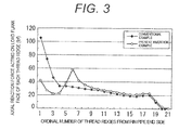
Fig. 3] Fig. 3 is a graph exemplifying an axial reaction force which acts on load flank faces of respective threads of an externally-threaded portion at the time of fastening the threaded joint. - [
Fig. 4] Fig. 4 is schematic explanatory views exemplifying a conventional special threaded joint. - An embodiment of the present invention is explained by reference to
Fig. 1 . The threaded joint according to the present invention has the substantially same constitution as the conventional premium joint exemplified inFig. 4 with respect to the point that the threaded joint includes:pins 3 each of which occupies a pipe end portion of a steel pipe 2 for an oil country tubular goods, and includes a externally-threadedportion 7, anose portion 8 which extends toward a pipe end side from the externally-threadedportion 7, and ashoulder portion 12 forming a distal end of thenose portion 8; and abox 1 which includes internally-threadedportions 5 each forming a threaded portion by being threadedly joined with the externally-threadedportion 7, andshoulder portions 14 which are brought into contact with theshoulder portions 12 of thepins 3, wherein thepins 3 and thebox 1 are joined to each other by the threaded joining so that portions between the threadedportions shoulder portions seal portions shoulder portions 12 of thepins 3 andshoulder portions 14 of thebox 1 form shoulder faces which are brought into contact with each other at the time of fastening the threaded joint (seeFig. 1(a) ). - The technical feature of the present invention lies in that, in the internally-threaded
portion 5, a pitch change is made such that a internally-thread pitch 20B has the same value as an externally-thread pitch 20P from a thread end portion on a box end side to a pitch change position PCP taken on a box center side with respect to a position away from the thread end portion by 1/2 of an entire length of the threaded portion (seeFig. 1(b) ), and the internally-thread pitch 20B is changed to a value less than the externally-thread pitch 20P at the pitch change position PCP so that athread gap 10 defined above is gradually decreased from the pitch change position PCP to a position of the thread end portion on the box center side (seeFig. 1(c) ), and the thread gap is eventually set to a value which is 0.2 to 0.8 times as large as the thread gap before the pitch change is made. - By performing the above-mentioned pitch change, as shown in
Fig. 1(c) , after the pitch change is made (on a pin pipe end side with respect to the pitch change position PCP), theload flank face 30B gradually shifts toward a box end side as the position of a portion in the threaded portion approaches close to the pin pipe end and, as the result, thethread gap 10 is gradually decreased. Along with the decrease of thethread gap 10, agap 32 is formed between theload flank faces gap 32 becomes and hence, there arises an effect that a contact face pressure which acts on theload flank face 30P on a pin pipe end side is decreased (a face pressure decreasing effect). Accordingly, a concentrated load which acts on theload flank face 30P on a pin pipe end side at the time of fastening is dispersed so that it is possible to acquire an effect of effectively decreasing the load (referred to as a load dispersing effect). - When a final value of the gradually decreased
thread gap 10 exceeds 0. 8 times of the value of thethread gap 10 before the pitch change is made (in the region on the box end side with respect to the pitch change position PCP), the above-mentioned face pressure decreasing effect becomes insufficient. On the other hand, when the final value is less than 0.2 times of the value of thethread gap 10 before the pitch change is made, there is a possibility of the occurrence of galling due to the interference between stabbing flank faces 31P and 31B on a pin pipe end side. Accordingly, it is necessary to set the final value of the gradually decreasedthread gap 10 to 0.2 to 0.8 times of the value of thethread gap 10 before the pitch change is made. - When a length of a region in the pipe axis direction from the pitch change position PCP to an end of the internally-threaded
portion 5 on a box center side (referred to as a short-pitched region) is set excessively long, there arises a difficulty that an extremely accurate pitch change becomes necessary so that the threaded joint is not suitable for industrial production. There also arises a difficulty that when the short-pitched region includes a wide region where no concentrated load exists although a contact face pressure is increased only in the vicinity of a pin pipe end side, the above-mentioned load dispersing effect becomes insufficient. In view of the above, it is necessary to set the length of the short-pitched region to less than 1/2 of the entire length of the threaded portion. - When the length of the short-pitched region is excessively short, there is a possibility that a load diffusion effect becomes insufficient so that a concentrated load is generated in the threaded portion outside the short-pitched region. Accordingly, it is preferable to set the length of the short-pitched region to a length corresponding to an amount of three ridges in terms of the number of thread ridges (an amount of three pitches in terms of the thread pitch) or more.
-
Fig. 2 is graphs showing one example of the pitch change according to the present invention, whereinFig. 2(a) is a diagram setting the relationship between the number of thread ridges which are used as indices of the distance in the pipe axis direction from a pin pipe end side and the thread gap.Fig. 2(b) is a diagram setting the relationship between the number of thread ridges and the pitch of internally-threads. In this embodiment, a threaded joint which is constituted of: pins formed by applying thread cutting to end portions of a steel pipe having an outer diameter of 7-5/8" (inch) and a wall thickness of 0.625" (inch) ; and a box corresponding to the pins is used as a subject. The pitch change position PCP is set at the position where the number of thread ridges is 5, and the internal pitch is changed from 0.2000" (inch) to 0.1996" (inch) at this position. The number of thread ridges over the entire length of the threaded portion is larger than 20. - With respect to the threaded joint of this embodiment (present invention example), a pipe axis reaction force (concentrated load) which acts on a load flank face of each thread ridge portion is calculated by an FEM (finite element method). To compare the pipe axis reaction force with a pipe axis reaction force when the pitch change is not performed (conventional example), as shown in
Fig. 3 , it is understood that a concentrated load of the present invention example is lower than the concentrated load of the conventional example, and the maximum value is halved. - With respect to a threaded joint for an oil country tubular goods which includes: pins formed by applying thread cutting to pipe end portions of a steel pipe having an outer diameter of 9-5/8" (inch)and a wall thickness of 0.545" (inch); and a box corresponding to the pins, and has levels of data on sizes of threaded portions shown in Table 1, a Make & Break test in which fastening and releasing after fastening are repeatedly performed is carried out in accordance with ISO 13679:2002. The test conditions are set such that a thread interference amount is "High" (0.305 mm), a seal interference amount is "High" (1.016mm) and a fastening torque is "High" (50, 000 N-m). Here, the seal interference amount is a value which is twice as large as a largest value of a size in the pipe radial direction (a value per diameter) of a region where a portion which becomes a pin-side seal portion and a portion which becomes a box-side seal portion interfere with each other when a pin drawing and a box drawing are overlapped to each other such that their pipe axes and their shoulder portions agree with each other. The thread interference amount is a value which is twice as large as a size in the pipe radial direction (a value per diameter) of a region where a portion which becomes a pin-side threaded portion and a portion which becomes a box-side threaded portion interfere with each other in such a case.
- The result of the test is shown in Table 1. As shown in Table 1, galling is not generated at any levels with respect to the present invention examples so that the present invention examples have passed the Make & Break test.
- [Table 1]
[Table 1] Level No. Outside short-pitched region Entire length of threaded portion Within short-pitched region Make & Break test result Remarks Thread pitch Thread gap G0 Thread pitch Region length Thread gap Final value G1 Ratio G1/G0 [inch] [inch] [inch] [inch] [inch] [inch] [-] 1 0.2000 0.0040 4.500 0.1996 0.998 0.0020 0.50 Passed test through 4 passes without galling Present invention example 2 0.2000 0.0040 4.500 0.1997 1.997 0.0030 0.75 Passed test through 4 passes without galling Present invention example 3 0.2000 0.0040 4.500 0.1997 0.599 0.0009 0.23 Passed test through 4 passes without galling Present invention example 4 0.2000 0.0040 4.500 0.1993 0.797 0.0028 0.70 Passed test through 4 passes without galling Present invention example 5 0.2000 0.0040 4.500 - - 0.0040 1.00 Galling occurred in the 2nd pass Comparative example 6 0.2000 0.0040 4.500 0.1991 0.796 0.0036 0.90 Galling occurred in the 3rd pass Comparative example 7 0.2000 0.0040 4.500 0.1997 2.396 0.0004 0.10 Galling occurred in the 3rdpass Comparative example -
- 1:
- box
- 2:
- oil country tubular goods
- 3:
- pin
- 5:
- internally-threaded portion (box side)
- 7:
- externally-threaded portion (pin side)
- 8:
- nose portion (pin nose)
- 10:
- thread gap
- 11, 13:
- seal portion (metal to metal seal portion)
- 12:
- shoulder portion (pin side)
- 14:
- shoulder portion (box side)
- 20:
- thread pitch (auxiliary sign P means pin side, B means box side)
- 30:
- load flank face (auxiliary sign P means pin side, B means box side)
- 31:
- stabbing flank face (auxiliary sign P means pin side, B means box side)
- 32:
- gap (gap between load flank faces which face each other)
- PCP:
- pitch change position
Claims (1)
- A threaded joint for oil country tubular goods having excellent galling resistance comprising:pins each of which occupies a pipe end portion of a steel pipe for an oil country tubular goods, and includes an externally-threaded portion, a nose portion which extends toward a pipe end side from the externally-threaded portion, and a shoulder portion forming a distal end of the nose portion; anda box which includes internally-threaded portions each forming a threaded portion by being threadedly joined with the externally-threaded portion, and shoulder portions which are brought into contact with the shoulder portions of the pins,the pins and the box being joined to each other by the threaded joining so that portions between the threaded portions and the shoulder portions are brought into metal-to-metal contact with each other thus forming seal portions at the contact portions, andthe shoulder portions of the pins and the shoulder portions of the box forming shoulder faces which are brought into contact with each other at the time of fastening the threaded joint, whereina pitch change is made such that a internally-thread pitch has the same value as a externally-thread pitch from a thread end portion on a box end side to a pitch change position taken on a box center side with respect to a position away from the thread end portion by 1/2 of an entire length of the threaded portion, and the internally-thread pitch is changed to a value less than the externally-thread pitch at the pitch change position so that a thread gap is gradually decreased from the pitch change position to a position of the thread end portion on the box center side, and the thread gap is eventually set to a value which is 0.2 to 0.8 times as large as the thread gap before the pitch change is made,where the definition of the thread gap is as follows:The thread gap is a distance in a pipe axis direction between stabbing flank faces which face each other within a complete fitting range of the threaded portions of the pin and the box in a state where load flank faces which face each other on a box end side contact with each other with no gap therebetween within the complete fitting range of the threaded portions of the pin and the box.
Applications Claiming Priority (2)
| Application Number | Priority Date | Filing Date | Title |
|---|---|---|---|
| JP2013125332A JP5704191B2 (en) | 2013-06-14 | 2013-06-14 | Threaded joint for oil well pipes with excellent seizure resistance |
| PCT/JP2014/003055 WO2014199619A1 (en) | 2013-06-14 | 2014-06-09 | Threaded joint for oil well pipe |
Publications (3)
| Publication Number | Publication Date |
|---|---|
| EP3009725A1 true EP3009725A1 (en) | 2016-04-20 |
| EP3009725A4 EP3009725A4 (en) | 2016-06-15 |
| EP3009725B1 EP3009725B1 (en) | 2018-11-21 |
Family
ID=52021933
Family Applications (1)
| Application Number | Title | Priority Date | Filing Date |
|---|---|---|---|
| EP14811719.5A Active EP3009725B1 (en) | 2013-06-14 | 2014-06-09 | Threaded joint for oil country tubular goods |
Country Status (7)
| Country | Link |
|---|---|
| US (1) | US10125554B2 (en) |
| EP (1) | EP3009725B1 (en) |
| JP (1) | JP5704191B2 (en) |
| AR (1) | AR096607A1 (en) |
| BR (1) | BR112015028966B1 (en) |
| MX (1) | MX354111B (en) |
| WO (1) | WO2014199619A1 (en) |
Families Citing this family (4)
| Publication number | Priority date | Publication date | Assignee | Title |
|---|---|---|---|---|
| JP6037091B1 (en) * | 2015-03-30 | 2016-11-30 | Jfeスチール株式会社 | Pipe threaded joint |
| JP6633214B2 (en) * | 2016-09-16 | 2020-01-22 | 日本製鉄株式会社 | Threaded joint |
| JP6722290B2 (en) * | 2016-09-16 | 2020-07-15 | 日本製鉄株式会社 | Threaded joint |
| JP7421095B2 (en) * | 2020-03-30 | 2024-01-24 | 日本製鉄株式会社 | seamless steel pipe |
Family Cites Families (20)
| Publication number | Priority date | Publication date | Assignee | Title |
|---|---|---|---|---|
| US2204754A (en) * | 1938-12-29 | 1940-06-18 | Nat Supply Co | Threaded joint |
| US3050318A (en) * | 1955-10-31 | 1962-08-21 | Shell Oil Co | Box-and-pin type threaded joint |
| NL271091A (en) * | 1961-11-07 | 1964-07-27 | ||
| GB8323349D0 (en) * | 1983-08-31 | 1983-10-05 | Hunting Oilfield Services Ltd | Pipe connectors |
| GB8323348D0 (en) * | 1983-08-31 | 1983-10-05 | Hunting Oilfield Services Ltd | Pipe connectors |
| GB8323858D0 (en) * | 1983-09-06 | 1983-10-05 | Hunting Oilfield Services Ltd | Pipe connectors |
| US4688832A (en) * | 1984-08-13 | 1987-08-25 | Hydril Company | Well pipe joint |
| JPS62196488A (en) * | 1986-02-24 | 1987-08-29 | 住友金属工業株式会社 | Pipe joint for oil well pipe |
| JPS62196486A (en) * | 1986-02-24 | 1987-08-29 | 住友金属工業株式会社 | Pipe joint for oil well pipe |
| JPH0243948A (en) | 1988-08-03 | 1990-02-14 | Kao Corp | Adsorbent |
| CA1322773C (en) * | 1989-07-28 | 1993-10-05 | Erich F. Klementich | Threaded tubular connection |
| DE4431377C1 (en) * | 1994-08-29 | 1996-05-09 | Mannesmann Ag | Pipe connector |
| JPH09126367A (en) * | 1995-10-31 | 1997-05-13 | Kawasaki Steel Corp | Pipe joint |
| DE19739458C2 (en) * | 1997-09-03 | 1999-06-10 | Mannesmann Ag | Pipe connector |
| US6123368A (en) * | 1998-03-19 | 2000-09-26 | Hydril Company | Two-step, differential diameter wedge threaded connector |
| JP2001021072A (en) * | 1999-07-05 | 2001-01-26 | Nippon Steel Corp | Pipe joint excellent in seizure resistance and processing method thereof |
| FR2821916B1 (en) * | 2001-03-09 | 2003-05-16 | Vallourec Mannesmann Oil & Gas | THREADED ELEMENT FOR FATIGUE-RESISTANT TUBULAR THREADED JOINT |
| US7452007B2 (en) * | 2004-07-07 | 2008-11-18 | Weatherford/Lamb, Inc. | Hybrid threaded connection for expandable tubulars |
| CA2675894C (en) * | 2006-01-26 | 2013-03-26 | Ramos, Beverly Watts | Threaded pipe connection |
| FR2945604B1 (en) * | 2009-05-12 | 2011-06-03 | Vallourec Mannesmann Oil & Gas | ASSEMBLY FOR THE PRODUCTION OF A THREADED JOINT FOR DRILLING AND OPERATING HYDROCARBON WELLS AND RESULTING THREAD |
-
2013
- 2013-06-14 JP JP2013125332A patent/JP5704191B2/en active Active
-
2014
- 2014-06-09 EP EP14811719.5A patent/EP3009725B1/en active Active
- 2014-06-09 MX MX2015016315A patent/MX354111B/en active IP Right Grant
- 2014-06-09 WO PCT/JP2014/003055 patent/WO2014199619A1/en not_active Ceased
- 2014-06-09 BR BR112015028966-5A patent/BR112015028966B1/en active IP Right Grant
- 2014-06-09 US US14/897,802 patent/US10125554B2/en active Active
- 2014-06-13 AR ARP140102261A patent/AR096607A1/en active IP Right Grant
Also Published As
| Publication number | Publication date |
|---|---|
| WO2014199619A1 (en) | 2014-12-18 |
| US20160130884A1 (en) | 2016-05-12 |
| JP2015001253A (en) | 2015-01-05 |
| MX354111B (en) | 2018-02-14 |
| US10125554B2 (en) | 2018-11-13 |
| EP3009725A4 (en) | 2016-06-15 |
| EP3009725B1 (en) | 2018-11-21 |
| JP5704191B2 (en) | 2015-04-22 |
| MX2015016315A (en) | 2016-03-16 |
| BR112015028966A2 (en) | 2017-07-25 |
| AR096607A1 (en) | 2016-01-20 |
| BR112015028966B1 (en) | 2021-02-17 |
Similar Documents
| Publication | Publication Date | Title |
|---|---|---|
| EP3043098B1 (en) | Threaded connection for steel pipe | |
| EP3205918B1 (en) | Threaded joint for steel pipes | |
| CN102313085B (en) | Pipe screw joint | |
| CA3032483C (en) | Threaded joint for oil well pipe | |
| JP6654643B2 (en) | Screw joints for steel pipes | |
| CN104775761B (en) | Pole heavy wall screw coupling for oil well pipe | |
| JP5849749B2 (en) | Threaded joints for pipes | |
| EP3392543B1 (en) | Threaded joint for steel pipe | |
| WO2019093163A1 (en) | Threaded joint for steel pipes | |
| EP3009725B1 (en) | Threaded joint for oil country tubular goods | |
| US9951569B2 (en) | Threaded connection | |
| EP3246611B1 (en) | Screw joint for pipe | |
| EP2977662B1 (en) | Threaded joint for oil well pipe | |
| JP6020087B2 (en) | Threaded joints for pipes |
Legal Events
| Date | Code | Title | Description |
|---|---|---|---|
| PUAI | Public reference made under article 153(3) epc to a published international application that has entered the european phase |
Free format text: ORIGINAL CODE: 0009012 |
|
| 17P | Request for examination filed |
Effective date: 20160112 |
|
| AK | Designated contracting states |
Kind code of ref document: A1 Designated state(s): AL AT BE BG CH CY CZ DE DK EE ES FI FR GB GR HR HU IE IS IT LI LT LU LV MC MK MT NL NO PL PT RO RS SE SI SK SM TR |
|
| AX | Request for extension of the european patent |
Extension state: BA ME |
|
| REG | Reference to a national code |
Ref country code: DE Ref legal event code: R079 Ref document number: 602014036603 Country of ref document: DE Free format text: PREVIOUS MAIN CLASS: F16L0015040000 Ipc: E21B0017042000 |
|
| A4 | Supplementary search report drawn up and despatched |
Effective date: 20160517 |
|
| RIC1 | Information provided on ipc code assigned before grant |
Ipc: E21B 17/042 20060101AFI20160510BHEP Ipc: F16L 15/06 20060101ALI20160510BHEP Ipc: F16L 15/00 20060101ALI20160510BHEP |
|
| DAX | Request for extension of the european patent (deleted) | ||
| STAA | Information on the status of an ep patent application or granted ep patent |
Free format text: STATUS: EXAMINATION IS IN PROGRESS |
|
| 17Q | First examination report despatched |
Effective date: 20170522 |
|
| GRAP | Despatch of communication of intention to grant a patent |
Free format text: ORIGINAL CODE: EPIDOSNIGR1 |
|
| STAA | Information on the status of an ep patent application or granted ep patent |
Free format text: STATUS: GRANT OF PATENT IS INTENDED |
|
| INTG | Intention to grant announced |
Effective date: 20180308 |
|
| GRAJ | Information related to disapproval of communication of intention to grant by the applicant or resumption of examination proceedings by the epo deleted |
Free format text: ORIGINAL CODE: EPIDOSDIGR1 |
|
| STAA | Information on the status of an ep patent application or granted ep patent |
Free format text: STATUS: EXAMINATION IS IN PROGRESS |
|
| GRAP | Despatch of communication of intention to grant a patent |
Free format text: ORIGINAL CODE: EPIDOSNIGR1 |
|
| STAA | Information on the status of an ep patent application or granted ep patent |
Free format text: STATUS: GRANT OF PATENT IS INTENDED |
|
| INTC | Intention to grant announced (deleted) | ||
| INTG | Intention to grant announced |
Effective date: 20180703 |
|
| GRAS | Grant fee paid |
Free format text: ORIGINAL CODE: EPIDOSNIGR3 |
|
| GRAA | (expected) grant |
Free format text: ORIGINAL CODE: 0009210 |
|
| STAA | Information on the status of an ep patent application or granted ep patent |
Free format text: STATUS: THE PATENT HAS BEEN GRANTED |
|
| AK | Designated contracting states |
Kind code of ref document: B1 Designated state(s): AL AT BE BG CH CY CZ DE DK EE ES FI FR GB GR HR HU IE IS IT LI LT LU LV MC MK MT NL NO PL PT RO RS SE SI SK SM TR |
|
| REG | Reference to a national code |
Ref country code: CH Ref legal event code: EP |
|
| REG | Reference to a national code |
Ref country code: IE Ref legal event code: FG4D |
|
| REG | Reference to a national code |
Ref country code: DE Ref legal event code: R096 Ref document number: 602014036603 Country of ref document: DE |
|
| REG | Reference to a national code |
Ref country code: AT Ref legal event code: REF Ref document number: 1067750 Country of ref document: AT Kind code of ref document: T Effective date: 20181215 |
|
| REG | Reference to a national code |
Ref country code: NL Ref legal event code: MP Effective date: 20181121 |
|
| REG | Reference to a national code |
Ref country code: AT Ref legal event code: MK05 Ref document number: 1067750 Country of ref document: AT Kind code of ref document: T Effective date: 20181121 |
|
| PG25 | Lapsed in a contracting state [announced via postgrant information from national office to epo] |
Ref country code: ES Free format text: LAPSE BECAUSE OF FAILURE TO SUBMIT A TRANSLATION OF THE DESCRIPTION OR TO PAY THE FEE WITHIN THE PRESCRIBED TIME-LIMIT Effective date: 20181121 Ref country code: AT Free format text: LAPSE BECAUSE OF FAILURE TO SUBMIT A TRANSLATION OF THE DESCRIPTION OR TO PAY THE FEE WITHIN THE PRESCRIBED TIME-LIMIT Effective date: 20181121 Ref country code: LV Free format text: LAPSE BECAUSE OF FAILURE TO SUBMIT A TRANSLATION OF THE DESCRIPTION OR TO PAY THE FEE WITHIN THE PRESCRIBED TIME-LIMIT Effective date: 20181121 Ref country code: IS Free format text: LAPSE BECAUSE OF FAILURE TO SUBMIT A TRANSLATION OF THE DESCRIPTION OR TO PAY THE FEE WITHIN THE PRESCRIBED TIME-LIMIT Effective date: 20190321 Ref country code: FI Free format text: LAPSE BECAUSE OF FAILURE TO SUBMIT A TRANSLATION OF THE DESCRIPTION OR TO PAY THE FEE WITHIN THE PRESCRIBED TIME-LIMIT Effective date: 20181121 Ref country code: NO Free format text: LAPSE BECAUSE OF FAILURE TO SUBMIT A TRANSLATION OF THE DESCRIPTION OR TO PAY THE FEE WITHIN THE PRESCRIBED TIME-LIMIT Effective date: 20190221 Ref country code: LT Free format text: LAPSE BECAUSE OF FAILURE TO SUBMIT A TRANSLATION OF THE DESCRIPTION OR TO PAY THE FEE WITHIN THE PRESCRIBED TIME-LIMIT Effective date: 20181121 Ref country code: HR Free format text: LAPSE BECAUSE OF FAILURE TO SUBMIT A TRANSLATION OF THE DESCRIPTION OR TO PAY THE FEE WITHIN THE PRESCRIBED TIME-LIMIT Effective date: 20181121 Ref country code: BG Free format text: LAPSE BECAUSE OF FAILURE TO SUBMIT A TRANSLATION OF THE DESCRIPTION OR TO PAY THE FEE WITHIN THE PRESCRIBED TIME-LIMIT Effective date: 20190221 |
|
| PG25 | Lapsed in a contracting state [announced via postgrant information from national office to epo] |
Ref country code: GR Free format text: LAPSE BECAUSE OF FAILURE TO SUBMIT A TRANSLATION OF THE DESCRIPTION OR TO PAY THE FEE WITHIN THE PRESCRIBED TIME-LIMIT Effective date: 20190222 Ref country code: NL Free format text: LAPSE BECAUSE OF FAILURE TO SUBMIT A TRANSLATION OF THE DESCRIPTION OR TO PAY THE FEE WITHIN THE PRESCRIBED TIME-LIMIT Effective date: 20181121 Ref country code: SE Free format text: LAPSE BECAUSE OF FAILURE TO SUBMIT A TRANSLATION OF THE DESCRIPTION OR TO PAY THE FEE WITHIN THE PRESCRIBED TIME-LIMIT Effective date: 20181121 Ref country code: PT Free format text: LAPSE BECAUSE OF FAILURE TO SUBMIT A TRANSLATION OF THE DESCRIPTION OR TO PAY THE FEE WITHIN THE PRESCRIBED TIME-LIMIT Effective date: 20190321 Ref country code: AL Free format text: LAPSE BECAUSE OF FAILURE TO SUBMIT A TRANSLATION OF THE DESCRIPTION OR TO PAY THE FEE WITHIN THE PRESCRIBED TIME-LIMIT Effective date: 20181121 Ref country code: RS Free format text: LAPSE BECAUSE OF FAILURE TO SUBMIT A TRANSLATION OF THE DESCRIPTION OR TO PAY THE FEE WITHIN THE PRESCRIBED TIME-LIMIT Effective date: 20181121 |
|
| PG25 | Lapsed in a contracting state [announced via postgrant information from national office to epo] |
Ref country code: PL Free format text: LAPSE BECAUSE OF FAILURE TO SUBMIT A TRANSLATION OF THE DESCRIPTION OR TO PAY THE FEE WITHIN THE PRESCRIBED TIME-LIMIT Effective date: 20181121 Ref country code: CZ Free format text: LAPSE BECAUSE OF FAILURE TO SUBMIT A TRANSLATION OF THE DESCRIPTION OR TO PAY THE FEE WITHIN THE PRESCRIBED TIME-LIMIT Effective date: 20181121 Ref country code: DK Free format text: LAPSE BECAUSE OF FAILURE TO SUBMIT A TRANSLATION OF THE DESCRIPTION OR TO PAY THE FEE WITHIN THE PRESCRIBED TIME-LIMIT Effective date: 20181121 |
|
| REG | Reference to a national code |
Ref country code: DE Ref legal event code: R097 Ref document number: 602014036603 Country of ref document: DE |
|
| PG25 | Lapsed in a contracting state [announced via postgrant information from national office to epo] |
Ref country code: SK Free format text: LAPSE BECAUSE OF FAILURE TO SUBMIT A TRANSLATION OF THE DESCRIPTION OR TO PAY THE FEE WITHIN THE PRESCRIBED TIME-LIMIT Effective date: 20181121 Ref country code: RO Free format text: LAPSE BECAUSE OF FAILURE TO SUBMIT A TRANSLATION OF THE DESCRIPTION OR TO PAY THE FEE WITHIN THE PRESCRIBED TIME-LIMIT Effective date: 20181121 Ref country code: EE Free format text: LAPSE BECAUSE OF FAILURE TO SUBMIT A TRANSLATION OF THE DESCRIPTION OR TO PAY THE FEE WITHIN THE PRESCRIBED TIME-LIMIT Effective date: 20181121 Ref country code: SM Free format text: LAPSE BECAUSE OF FAILURE TO SUBMIT A TRANSLATION OF THE DESCRIPTION OR TO PAY THE FEE WITHIN THE PRESCRIBED TIME-LIMIT Effective date: 20181121 |
|
| PLBE | No opposition filed within time limit |
Free format text: ORIGINAL CODE: 0009261 |
|
| STAA | Information on the status of an ep patent application or granted ep patent |
Free format text: STATUS: NO OPPOSITION FILED WITHIN TIME LIMIT |
|
| 26N | No opposition filed |
Effective date: 20190822 |
|
| PG25 | Lapsed in a contracting state [announced via postgrant information from national office to epo] |
Ref country code: SI Free format text: LAPSE BECAUSE OF FAILURE TO SUBMIT A TRANSLATION OF THE DESCRIPTION OR TO PAY THE FEE WITHIN THE PRESCRIBED TIME-LIMIT Effective date: 20181121 |
|
| PG25 | Lapsed in a contracting state [announced via postgrant information from national office to epo] |
Ref country code: MC Free format text: LAPSE BECAUSE OF FAILURE TO SUBMIT A TRANSLATION OF THE DESCRIPTION OR TO PAY THE FEE WITHIN THE PRESCRIBED TIME-LIMIT Effective date: 20181121 |
|
| REG | Reference to a national code |
Ref country code: CH Ref legal event code: PL |
|
| GBPC | Gb: european patent ceased through non-payment of renewal fee |
Effective date: 20190609 |
|
| REG | Reference to a national code |
Ref country code: BE Ref legal event code: MM Effective date: 20190630 |
|
| PG25 | Lapsed in a contracting state [announced via postgrant information from national office to epo] |
Ref country code: TR Free format text: LAPSE BECAUSE OF FAILURE TO SUBMIT A TRANSLATION OF THE DESCRIPTION OR TO PAY THE FEE WITHIN THE PRESCRIBED TIME-LIMIT Effective date: 20181121 |
|
| PG25 | Lapsed in a contracting state [announced via postgrant information from national office to epo] |
Ref country code: IE Free format text: LAPSE BECAUSE OF NON-PAYMENT OF DUE FEES Effective date: 20190609 Ref country code: GB Free format text: LAPSE BECAUSE OF NON-PAYMENT OF DUE FEES Effective date: 20190609 |
|
| PG25 | Lapsed in a contracting state [announced via postgrant information from national office to epo] |
Ref country code: LI Free format text: LAPSE BECAUSE OF NON-PAYMENT OF DUE FEES Effective date: 20190630 Ref country code: LU Free format text: LAPSE BECAUSE OF NON-PAYMENT OF DUE FEES Effective date: 20190609 Ref country code: BE Free format text: LAPSE BECAUSE OF NON-PAYMENT OF DUE FEES Effective date: 20190630 Ref country code: CH Free format text: LAPSE BECAUSE OF NON-PAYMENT OF DUE FEES Effective date: 20190630 |
|
| PG25 | Lapsed in a contracting state [announced via postgrant information from national office to epo] |
Ref country code: CY Free format text: LAPSE BECAUSE OF FAILURE TO SUBMIT A TRANSLATION OF THE DESCRIPTION OR TO PAY THE FEE WITHIN THE PRESCRIBED TIME-LIMIT Effective date: 20181121 |
|
| PG25 | Lapsed in a contracting state [announced via postgrant information from national office to epo] |
Ref country code: MT Free format text: LAPSE BECAUSE OF FAILURE TO SUBMIT A TRANSLATION OF THE DESCRIPTION OR TO PAY THE FEE WITHIN THE PRESCRIBED TIME-LIMIT Effective date: 20181121 Ref country code: HU Free format text: LAPSE BECAUSE OF FAILURE TO SUBMIT A TRANSLATION OF THE DESCRIPTION OR TO PAY THE FEE WITHIN THE PRESCRIBED TIME-LIMIT; INVALID AB INITIO Effective date: 20140609 |
|
| PG25 | Lapsed in a contracting state [announced via postgrant information from national office to epo] |
Ref country code: MK Free format text: LAPSE BECAUSE OF FAILURE TO SUBMIT A TRANSLATION OF THE DESCRIPTION OR TO PAY THE FEE WITHIN THE PRESCRIBED TIME-LIMIT Effective date: 20181121 |
|
| PGFP | Annual fee paid to national office [announced via postgrant information from national office to epo] |
Ref country code: DE Payment date: 20250429 Year of fee payment: 12 |
|
| PGFP | Annual fee paid to national office [announced via postgrant information from national office to epo] |
Ref country code: IT Payment date: 20250522 Year of fee payment: 12 |
|
| PGFP | Annual fee paid to national office [announced via postgrant information from national office to epo] |
Ref country code: FR Payment date: 20250508 Year of fee payment: 12 |