EP3009640A1 - Fuel system for tone control and operability - Google Patents
Fuel system for tone control and operability Download PDFInfo
- Publication number
- EP3009640A1 EP3009640A1 EP15190457.0A EP15190457A EP3009640A1 EP 3009640 A1 EP3009640 A1 EP 3009640A1 EP 15190457 A EP15190457 A EP 15190457A EP 3009640 A1 EP3009640 A1 EP 3009640A1
- Authority
- EP
- European Patent Office
- Prior art keywords
- nozzles
- valve
- flow number
- primary flow
- group
- Prior art date
- Legal status (The legal status is an assumption and is not a legal conclusion. Google has not performed a legal analysis and makes no representation as to the accuracy of the status listed.)
- Granted
Links
Images



Classifications
-
- F—MECHANICAL ENGINEERING; LIGHTING; HEATING; WEAPONS; BLASTING
- F02—COMBUSTION ENGINES; HOT-GAS OR COMBUSTION-PRODUCT ENGINE PLANTS
- F02C—GAS-TURBINE PLANTS; AIR INTAKES FOR JET-PROPULSION PLANTS; CONTROLLING FUEL SUPPLY IN AIR-BREATHING JET-PROPULSION PLANTS
- F02C9/00—Controlling gas-turbine plants; Controlling fuel supply in air- breathing jet-propulsion plants
- F02C9/26—Control of fuel supply
- F02C9/263—Control of fuel supply by means of fuel metering valves
-
- F—MECHANICAL ENGINEERING; LIGHTING; HEATING; WEAPONS; BLASTING
- F02—COMBUSTION ENGINES; HOT-GAS OR COMBUSTION-PRODUCT ENGINE PLANTS
- F02C—GAS-TURBINE PLANTS; AIR INTAKES FOR JET-PROPULSION PLANTS; CONTROLLING FUEL SUPPLY IN AIR-BREATHING JET-PROPULSION PLANTS
- F02C7/00—Features, components parts, details or accessories, not provided for in, or of interest apart form groups F02C1/00 - F02C6/00; Air intakes for jet-propulsion plants
- F02C7/22—Fuel supply systems
- F02C7/228—Dividing fuel between various burners
-
- F—MECHANICAL ENGINEERING; LIGHTING; HEATING; WEAPONS; BLASTING
- F02—COMBUSTION ENGINES; HOT-GAS OR COMBUSTION-PRODUCT ENGINE PLANTS
- F02C—GAS-TURBINE PLANTS; AIR INTAKES FOR JET-PROPULSION PLANTS; CONTROLLING FUEL SUPPLY IN AIR-BREATHING JET-PROPULSION PLANTS
- F02C7/00—Features, components parts, details or accessories, not provided for in, or of interest apart form groups F02C1/00 - F02C6/00; Air intakes for jet-propulsion plants
- F02C7/22—Fuel supply systems
- F02C7/232—Fuel valves; Draining valves or systems
-
- F—MECHANICAL ENGINEERING; LIGHTING; HEATING; WEAPONS; BLASTING
- F02—COMBUSTION ENGINES; HOT-GAS OR COMBUSTION-PRODUCT ENGINE PLANTS
- F02C—GAS-TURBINE PLANTS; AIR INTAKES FOR JET-PROPULSION PLANTS; CONTROLLING FUEL SUPPLY IN AIR-BREATHING JET-PROPULSION PLANTS
- F02C9/00—Controlling gas-turbine plants; Controlling fuel supply in air- breathing jet-propulsion plants
- F02C9/26—Control of fuel supply
- F02C9/32—Control of fuel supply characterised by throttling of fuel
- F02C9/34—Joint control of separate flows to main and auxiliary burners
-
- F—MECHANICAL ENGINEERING; LIGHTING; HEATING; WEAPONS; BLASTING
- F05—INDEXING SCHEMES RELATING TO ENGINES OR PUMPS IN VARIOUS SUBCLASSES OF CLASSES F01-F04
- F05D—INDEXING SCHEME FOR ASPECTS RELATING TO NON-POSITIVE-DISPLACEMENT MACHINES OR ENGINES, GAS-TURBINES OR JET-PROPULSION PLANTS
- F05D2260/00—Function
- F05D2260/96—Preventing, counteracting or reducing vibration or noise
-
- F—MECHANICAL ENGINEERING; LIGHTING; HEATING; WEAPONS; BLASTING
- F05—INDEXING SCHEMES RELATING TO ENGINES OR PUMPS IN VARIOUS SUBCLASSES OF CLASSES F01-F04
- F05D—INDEXING SCHEME FOR ASPECTS RELATING TO NON-POSITIVE-DISPLACEMENT MACHINES OR ENGINES, GAS-TURBINES OR JET-PROPULSION PLANTS
- F05D2270/00—Control
- F05D2270/01—Purpose of the control system
- F05D2270/14—Purpose of the control system to control thermoacoustic behaviour in the combustion chambers
Definitions
- Aircraft engines typically include turbomachinery that is configured for low noise and one or more combustors configured for low nitrogen oxides NOx (e.g., NO and NO 2 ) emissions and operability.
- NOx nitrogen oxides
- the relative contribution of acoustic tones from the combustor to overall noise increases as the contribution of other noise sources is reduced.
- Reduction in tone amplitude has been demonstrated by creation of local circumferential zones where fuel-air ratio varies. The zones have varying delay times that are observed prior to a release of heat, and consequently, a different coupling to naturally occurring acoustic frequencies.
- aspects of the disclosure are directed to a method for controlling a distribution of fuel to a plurality of nozzles associated with at least one aircraft engine, the method comprising: determining a state of operation associated with the at least one aircraft engine, causing a valve coupled to a fuel supply and each of the nozzles to open when it is determined that the state of operation indicates a high power state relative to at least one threshold, and causing the valve to close when it is determined that the state of operation indicates a low power state relative to the at least one threshold.
- the method further comprises establishing a first primary flow number for a first group of the nozzles, and establishing a second primary flow number that is different from the first primary flow number for a second group of the nozzles.
- the second primary flow number is less than the first primary flow number, wherein the first group of nozzles is located at a higher altitude than the second group of nozzles.
- the fuel supply is coupled to a first group of the nozzles via a primary line
- the valve is coupled to a second group of the nozzles via a secondary line.
- the method further comprises establishing a differential pressure of approximately 20 pounds per square inch (137 kPa) between the primary line and the secondary line when the valve is open, and establishing a differential pressure of approximately 120 pounds per square inch (827 kPa) between the primary line and the secondary line when the valve is closed.
- aspects of the disclosure are directed to a system for controlling a distribution of fuel on an aircraft, the system comprising: a plurality of nozzles associated with at least one aircraft engine, and a valve coupled to a fuel supply and each of the nozzles, wherein the valve is configured to be opened when a state of operation associated with the at least one aircraft engine indicates a high power state relative to at least one threshold, and wherein the valve is configured to be closed when the state of operation associated with the at least one aircraft engine indicates a low power state relative to the at least one threshold.
- the system further comprises: a primary line configured to couple the fuel supply to a subset of the nozzles, and a secondary line configured to couple the valve and each of the nozzles.
- the valve is configured to establish a differential pressure of approximately 20 pounds per square inch (137 kPa) between the primary line and the secondary line when the valve is open, and the valve is configured to establish a differential pressure of approximately 120 pounds per square inch (827 kPa) between the primary line and the secondary line when the valve is closed.
- the subset of nozzles corresponds to between one-sixth and one-third of the plurality of nozzles, inclusive.
- the nozzles are arranged in a ring.
- a first group of the nozzles has an associated first primary flow number
- a second group of the nozzles has an associated second primary flow number that is different from the first primary flow number.
- the second primary flow number is less than the first primary flow number, and the first group of nozzles is located at a higher altitude than the second group of nozzles.
- the first primary flow number and the second primary flow number are each expressed as an amount of fuel flow divided by the square root of a pressure drop, and the first primary flow number is equal to approximately 2.0, and the second primary flow number is equal to approximately 1.5.
- the first primary flow number is based on a first size of holes machined into the first group of nozzles
- the second primary flow number is based on a second size of holes machined into the second group of nozzles, and the second size is different from the first size.
- aspects of the disclosure are directed to a system for controlling a distribution of fuel on an aircraft, the system comprising: a first manifold inlet coupled to a subset of a plurality of nozzles, a second manifold inlet coupled to each of the nozzles, a primary line coupled to the first manifold inlet and a fuel supply, a valve coupled to the fuel supply, and a secondary line coupled to the valve and the second manifold inlet.
- the valve is configured to be opened when a state of operation associated with at least one engine of the aircraft indicates a high power state relative to at least one threshold, and the valve is configured to be closed when the state of operation associated with the at least one engine indicates a low power state relative to the at least one threshold, and the at least one threshold is based on a maximum thrust associated with the at least one engine.
- the system further comprises at least one processor, and memory having instructions stored thereon that, when executed by the at least one processor, cause the system to: determine a state of operation associated with at least one engine of the aircraft, cause the valve to open when it is determined that the state of operation indicates a high power state relative to at least one threshold, and cause the valve to close when it is determined that the state of operation indicates a low power state relative to the at least one threshold.
- the valve is configured to establish a differential pressure of approximately 20 pounds per square inch (137 kPa) between the primary line and the secondary line when the valve is open, and the valve is configured to establish a differential pressure of approximately 120 pounds per square inch (827 kPa) between the primary line and the secondary line when the valve is closed.
- a first group of the subset of the nozzles has an associated first primary flow number
- a second group of the subset of the nozzles has an associated second primary flow number that is different from the first primary flow number.
- the second primary flow number is less than the first primary flow number
- the first group of nozzles is located at a higher altitude than the second group of nozzles.
- the first primary flow number and the second primary flow number are each expressed as an amount of fuel flow divided by the square root of a pressure drop, and the first primary flow number is equal to approximately 2.0, and the second primary flow number is equal to approximately 1.5.
- connections are set forth between elements in the following description and in the drawings (the contents of which are included in this disclosure by way of reference). It is noted that these connections are general and, unless specified otherwise, may be direct or indirect and that this specification is not intended to be limiting in this respect.
- a coupling between two or more entities may refer to a direct connection or an indirect connection.
- An indirect connection may incorporate one or more intervening entities.
- apparatuses, systems and methods are described for creating local fuel-air ratio zones by use of differing fuel injector types and control valves.
- the local fuel air control is also used to enhance stability on snap or instantaneous transient decelerations.
- fuel may be distributed in a nonuniform/asymmetric manner with respect to a number of nozzles in order to minimize/reduce the impact or generation of such tones.
- the asymmetric distribution of fuel in the low power state/condition may help to increase the so-called lead blowout margin, which is a measure of the margin that is available in response to a transient condition (e.g., an invocation of a control, such as a pilot command imposed on a throttle, that causes an engine to decelerate) before the engine would need to be reignited.
- a transient condition e.g., an invocation of a control, such as a pilot command imposed on a throttle, that causes an engine to decelerate
- fuel may be distributed in a uniform/symmetric manner with respect to the nozzles in order to control temperature streaks going into the turbine and enhance engine durability.
- a comparison may be made between one or more parameters and one or more thresholds for purposes of determining whether the aircraft or engine is operating in the low power state/condition or the high power state/condition.
- a low power state/condition may correspond to operation at less than 50% of maximum thrust and a high power state/condition may correspond to operation at, or greater than, 50% of maximum thrust.
- FIG. 1 is a side-sectional illustration of an exemplary gas turbine engine 10.
- the engine 10 includes a compressor section 12, a turbine section 14 and one or more engine hot sections.
- the engine hot sections may include, for example, a first engine hot section 16 configured as a combustor section and a second engine hot section 18 configured as an augmentor section.
- the compressor section 12, the first engine hot section 16, the turbine section 14 and the second engine hot section 18 may be sequentially aligned along an axial centerline 20 between a forward engine airflow inlet 22 and an aft engine airflow exhaust 24.
- the system 200 includes two inlets, denoted as a first inlet 202 and a second inlet 204.
- the first inlet 202 may be used for purposes of supplying a primary (pressure atomizing spray) fuel to a number of nozzles 206 via a first set of pipes 208.
- the second inlet 204 may be used for purposes of providing a secondary fuel source via a second set of the pipes 208, where the second set of the pipes 208 may be different from the first set of the pipes 208 associated with the first inlet 202.
- the primary fuel might only be provided to a subset of the nozzles 206, where the subset is less than the entirety of the nozzles 206, and the secondary fuel may be provided to all of the nozzles 206.
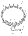
- a manifold architecture/system 300 is shown.
- the system 300 may correspond to the system 200.
- the system 300 is composed of a number of nozzles arranged as one or more groups.
- groups 306-1a and 306-1b may each include six nozzles and groups 306-2a and 306-2b may each include three nozzles, providing for a total of eighteen nozzles in the system 300.
- the total number of nozzles, or the number of nozzles included in a given group may be different.
- the groups 306-1a and 306-1b may include duplex nozzles, whereas the groups 306-2a and 306-2b may include simplex nozzles.
- a duplex nozzle is configured to receive both primary fuel (e.g., from the primary source/inlet 202 of FIG. 2 ) and secondary fuel (e.g., from the secondary source/inlet 204 of FIG. 2 ).
- a simplex nozzle is configured to receive secondary fuel, but not primary fuel.
- between one-sixth (1/6) and one-third (1/3) (inclusive) of the nozzles included in a system may be simplex nozzles.
- duplex nozzle group 306-1a, simplex nozzle group 306-2a, duplex nozzle group 306-1b, and simplex nozzle group 306-2b in FIG. 3 may be used to reduce the tones of a circumferential or tangential pressure wave inside a combustor (e.g., combustor/first engine hot section 16 of FIG. 1 ) by disrupting the pressure wave inside the combustor.
- a combustor e.g., combustor/first engine hot section 16 of FIG. 1
- FIG. 4 a schematic diagram of a system 400 is shown.
- fuel from a fuel supply 402 is shown as being provided to a first group of nozzles/primary manifold 406-1 via a primary line/channel 408-1.
- the first group of nozzles 406-1 may include, or be associated with, the nozzles that are included in the groups 306-1a and 306-1b of FIG. 3 .
- the fuel from the supply 402 is also provided to a second group of nozzles/secondary manifold 406-2 via a secondary line/channel 408-2.
- the second group of nozzles 406-2 may include, or be associated with, all of the nozzles of FIG. 3 (e.g., all of the nozzles included in the groups 306-1a, 306-1b, 306-2a, and 306-2b).
- One or both of the lines 408-1 and 408-2 may correspond to the pipes 208 of FIG. 2 .
- the system 400 may include a valve 432.
- the valve 432 may be implemented using a solenoid.
- the valve 432 may be used to establish a differential pressure between the primary line 408-1 and the secondary line 408-2. For example, if the valve 432 transitions from an open state to a closed state, an increase in a fuel pressure drop may be experienced by the group 406-1 relative to the group 406-2. This increase in the fuel pressure drop may be accompanied by an increase in fuel flow to the group 406-1 relative to the group 406-2, such that the distribution of the fuel from the supply 402 to the groups 406-1 and 406-2 may be non-uniform/asymmetric.
- the valve 432 may be closed to accommodate the low power state/condition described above.
- valve 432 transitions from a closed state to an open state, a decrease in the fuel pressure drop may be experienced by the group 406-1 relative to the group 406-2.
- This decrease in the fuel pressure drop may be accompanied by a decrease in fuel flow to the group 406-1 relative to the group 406-2, such that the distribution of the fuel from the supply 402 to the groups 406-1 and 406-2 may be uniform/symmetric.
- the valve 432 may be opened to accommodate the high power state/condition described above.
- a differential pressure of approximately 120 pounds per square inch (psi) (827 kPa) may be established between the primary line 408-1 and the secondary line 408-2.
- psi pounds per square inch
- a differential pressure of approximately 20 psi (137 kPa) may be established between the primary line 408-1 and the second line 408-2.
- a single valve 432 may be used to selectively control the distribution of fuel flow in the system 400. This represents a departure from techniques where each nozzle was allocated its own valve. Accordingly, the use of a single valve 432 represents a reduction in cost in terms of the nozzles and increases the reliability of the system 400.
- Some of the manifolds described herein reflect an arrangement of nozzles (e.g., nozzles 206) or groups of nozzles (e.g., groups 306-1a, 306-1b, 306-2a, and 306-2b) in a ring shape/configuration.
- nozzles e.g., nozzles 206
- groups of nozzles e.g., groups 306-1a, 306-1b, 306-2a, and 306-2b
- Such ring manifolds may experience a fuel mal-distribution (e.g., a nonuniform circumferential distribution of fuel within the ring) due to head-effects, particularly in the presence of low fuel flows (e.g., a low fuel supply 402).
- the head-effects may be at least partially a result of gravity.
- the head-effects may cause a greater fuel flow to be experienced by lower or bottom nozzles (e.g., nozzles in the group 306-1b) relative to nozzles located at a higher altitude/elevation (e.g., nozzles in the group 306-1a) in the orientation as shown.
- a first primary flow number may be established for nozzles located at a higher altitude (e.g., nozzles in the group 306-1a) in the ring and a second primary flow number that is different from (e.g., less than) the first primary flow number may be established for nozzles located in the lower/bottom portion (e.g., nozzles in the group 306-1b) of the ring.
- a primary flow number may represent a measure of flow capacity.
- the primary flow number may be expressed as an amount of fuel flow divided by the square root of a pressure drop.
- the first primary flow number described above may have a value of approximately 2.0 and the second primary flow number described above may have a value of approximately 1.5.
- the values for the first primary flow number and the second primary flow may be established based on a size of holes that are machined in the respective nozzles. For example, the size of the holes may be different so as to cause different primary flow numbers to be established.
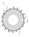
- the tip of the nozzle 500 may be cylindrical in shape.
- the nozzle 500 may include a primary hole/passage 542 that may be operative based on an applied pressure to generate fuel spray/droplets.
- the nozzle 500 may include secondary holes/passages 544 that may be operative based on an airflow in generating fuel spray/droplets.
- the primary passage 542 may be supplied fuel via the inlet 202 of FIG. 2 and/or the primary line 408-1 of FIG. 4 .
- the secondary passages 544 may be supplied fuel via the inlet 204 of FIG. 2 and/or the secondary line 408-2 of FIG. 4 .
- a simplex nozzle might not include the passage 542.
- the primary passage 542 may be used for igniting an engine (e.g., engine 10 of FIG. 1 ).
- the primary passage 542 may be used to reignite the engine at altitude, where airflow may be insufficient to facilitate generation of the fuel spray/droplets via the secondary passages 544.
- FIG. 5 is not necessarily drawn to scale.
- the count and/or location of the passage 542 and/or the passages 544 may be different from what is shown.
- a size/dimension of the passage 542 may be different from (e.g., smaller than) than a corresponding size/dimension of the passages 544.
- the system 600 includes one or more processors (generally shown by a processor 602) and a memory 604.
- the memory 604 may store data 606 and/or instructions 608.
- the system 600 may include a computer-readable medium (CRM) 610 that may store some or all of the instructions 608.
- CRM 610 may include a transitory and/or non-transitory computer-readable medium.
- the data 606 may include total fuel flow, rotor speed, derivative of rotor speed or change in rotor speed, fuel-air ratio, etc.
- the data 606 may be analyzed to control a distribution of fuel flow and/or to control the state of a valve (e.g., valve 432 of FIG. 4 ).
- the system 600 may include one or more input/output (I/O) devices 612 that may be used to provide an interface between the system 600 and one or more additional systems or entities.
- the I/O devices 612 may include one or more of a graphical user interface (GUI), a display screen, a touchscreen, a keyboard, a mouse, a joystick, a pushbutton, a microphone, a speaker, a microphone, a transceiver, etc.
- the I/O devices 612 may include one or more sensors that may be configured to measure/detect one or more parameters associated with the operation of an aircraft, such as the state of one or more pilot controls that may have an impact on how fuel should be distributed.
- the I/O devices 612/system 600 may include an engine controller configured to gather data and perform calculations to generate one or more commands, potentially based on one or more parameters.
- the system 600 is illustrative. In some embodiments, one or more of the components or devices may be optional. In some embodiments, the components/devices may be arranged in a manner that is different from what is shown in FIG. 6 . In some embodiments, additional components or devices not shown may be included. For example, in embodiments where the system 600 is included as part of one or more networks, one or more switches, routers, and the like may be included.
- FIG. 7 is a flow chart of a method 700.
- the method 700 may be executed by, or tied to, one or more systems, devices, or components, such as those described herein.
- the method 700 may be executed by the processor 602 of FIG. 6 in order to control or regulate a distribution of fuel with respect to one or more nozzles associated with an aircraft engine.
- a determination may be made whether the aircraft or engine is operating in a high power state or a low power state. Such a determination may be based on an examination of one or more parameters, potentially with respect to (e.g., in comparison to) one or more thresholds. The parameters and/or thresholds may be included in the data 606 of FIG. 6 . If the determination of block 702 indicates operation in the high power state, flow may proceed from block 702 to block 704. Otherwise the operation is in the low power state and flow may proceed from block 702 to block 706.
- a valve e.g., valve 432 of FIG. 4
- a valve may be opened (or remain open) to provide for a uniform/symmetric flow of fuel.
- a valve e.g., valve 432 of FIG. 4
- a valve may be closed (or remain closed) to provide for a non-uniform/asymmetric flow of fuel.
- control exerted over the distribution of the fuel may be used to reduce a level of noise that is output by the aircraft or an associated device/component. As a rough order of magnitude, the noise may be reduced on the order of approximately 20dB in some embodiments via incorporation of the techniques that are described herein.
- control exerted over the distribution of fuel may improve or enhance engine stability, particularly under low power or low fuel flow conditions by enhancing or enriching a subset of nozzles in terms of fuel availability/output.
Landscapes
- Engineering & Computer Science (AREA)
- Chemical & Material Sciences (AREA)
- Combustion & Propulsion (AREA)
- Mechanical Engineering (AREA)
- General Engineering & Computer Science (AREA)
- Fuel-Injection Apparatus (AREA)
Abstract
Description
- Aircraft engines typically include turbomachinery that is configured for low noise and one or more combustors configured for low nitrogen oxides NOx (e.g., NO and NO2) emissions and operability. The relative contribution of acoustic tones from the combustor to overall noise increases as the contribution of other noise sources is reduced. Reduction in tone amplitude has been demonstrated by creation of local circumferential zones where fuel-air ratio varies. The zones have varying delay times that are observed prior to a release of heat, and consequently, a different coupling to naturally occurring acoustic frequencies.
- The following presents a simplified summary in order to provide a basic understanding of some aspects of the disclosure. The summary is not an extensive overview of the disclosure. It is neither intended to identify key or critical elements of the disclosure nor to delineate the scope of the disclosure. The following summary merely presents some concepts of the disclosure in a simplified form as a prelude to the description below.
- Aspects of the disclosure are directed to a method for controlling a distribution of fuel to a plurality of nozzles associated with at least one aircraft engine, the method comprising: determining a state of operation associated with the at least one aircraft engine, causing a valve coupled to a fuel supply and each of the nozzles to open when it is determined that the state of operation indicates a high power state relative to at least one threshold, and causing the valve to close when it is determined that the state of operation indicates a low power state relative to the at least one threshold. In some embodiments, the method further comprises establishing a first primary flow number for a first group of the nozzles, and establishing a second primary flow number that is different from the first primary flow number for a second group of the nozzles. In some embodiments, the second primary flow number is less than the first primary flow number, wherein the first group of nozzles is located at a higher altitude than the second group of nozzles. In some embodiments, the fuel supply is coupled to a first group of the nozzles via a primary line, and the valve is coupled to a second group of the nozzles via a secondary line. In some embodiments, the method further comprises establishing a differential pressure of approximately 20 pounds per square inch (137 kPa) between the primary line and the secondary line when the valve is open, and establishing a differential pressure of approximately 120 pounds per square inch (827 kPa) between the primary line and the secondary line when the valve is closed.
- Aspects of the disclosure are directed to a system for controlling a distribution of fuel on an aircraft, the system comprising: a plurality of nozzles associated with at least one aircraft engine, and a valve coupled to a fuel supply and each of the nozzles, wherein the valve is configured to be opened when a state of operation associated with the at least one aircraft engine indicates a high power state relative to at least one threshold, and wherein the valve is configured to be closed when the state of operation associated with the at least one aircraft engine indicates a low power state relative to the at least one threshold. In some embodiments, the system further comprises: a primary line configured to couple the fuel supply to a subset of the nozzles, and a secondary line configured to couple the valve and each of the nozzles. In some embodiments, the valve is configured to establish a differential pressure of approximately 20 pounds per square inch (137 kPa) between the primary line and the secondary line when the valve is open, and the valve is configured to establish a differential pressure of approximately 120 pounds per square inch (827 kPa) between the primary line and the secondary line when the valve is closed. In some embodiments, the subset of nozzles corresponds to between one-sixth and one-third of the plurality of nozzles, inclusive. In some embodiments, the nozzles are arranged in a ring. In some embodiments, a first group of the nozzles has an associated first primary flow number, and a second group of the nozzles has an associated second primary flow number that is different from the first primary flow number. In some embodiments, the second primary flow number is less than the first primary flow number, and the first group of nozzles is located at a higher altitude than the second group of nozzles. In some embodiments, the first primary flow number and the second primary flow number are each expressed as an amount of fuel flow divided by the square root of a pressure drop, and the first primary flow number is equal to approximately 2.0, and the second primary flow number is equal to approximately 1.5. In some embodiments, the first primary flow number is based on a first size of holes machined into the first group of nozzles, and the second primary flow number is based on a second size of holes machined into the second group of nozzles, and the second size is different from the first size.
- Aspects of the disclosure are directed to a system for controlling a distribution of fuel on an aircraft, the system comprising: a first manifold inlet coupled to a subset of a plurality of nozzles, a second manifold inlet coupled to each of the nozzles, a primary line coupled to the first manifold inlet and a fuel supply, a valve coupled to the fuel supply, and a secondary line coupled to the valve and the second manifold inlet. In some embodiments, the valve is configured to be opened when a state of operation associated with at least one engine of the aircraft indicates a high power state relative to at least one threshold, and the valve is configured to be closed when the state of operation associated with the at least one engine indicates a low power state relative to the at least one threshold, and the at least one threshold is based on a maximum thrust associated with the at least one engine. In some embodiments, the system further comprises at least one processor, and memory having instructions stored thereon that, when executed by the at least one processor, cause the system to: determine a state of operation associated with at least one engine of the aircraft, cause the valve to open when it is determined that the state of operation indicates a high power state relative to at least one threshold, and cause the valve to close when it is determined that the state of operation indicates a low power state relative to the at least one threshold. In some embodiments, the valve is configured to establish a differential pressure of approximately 20 pounds per square inch (137 kPa) between the primary line and the secondary line when the valve is open, and the valve is configured to establish a differential pressure of approximately 120 pounds per square inch (827 kPa) between the primary line and the secondary line when the valve is closed. In some embodiments, a first group of the subset of the nozzles has an associated first primary flow number, and a second group of the subset of the nozzles has an associated second primary flow number that is different from the first primary flow number. In some embodiments, the second primary flow number is less than the first primary flow number, and the first group of nozzles is located at a higher altitude than the second group of nozzles. In some embodiments, the first primary flow number and the second primary flow number are each expressed as an amount of fuel flow divided by the square root of a pressure drop, and the first primary flow number is equal to approximately 2.0, and the second primary flow number is equal to approximately 1.5.
- The present disclosure is illustrated by way of example and not limited in the accompanying figures in which like reference numerals indicate similar elements.
-
FIG. 1 illustrates an exemplary gas turbine engine. -
FIG. 2 illustrates an exemplary manifold system. -
FIG. 3 illustrates an exemplary system incorporating nozzles arranged as groups. -
FIG. 4 illustrates a schematic of an example fuel distribution system. -
FIG. 5 illustrates a tip of an exemplary nozzle. -
FIG. 6 illustrates an exemplary computing system. -
FIG. 7 illustrates a flow chart of an exemplary method. - It is noted that various connections are set forth between elements in the following description and in the drawings (the contents of which are included in this disclosure by way of reference). It is noted that these connections are general and, unless specified otherwise, may be direct or indirect and that this specification is not intended to be limiting in this respect. A coupling between two or more entities may refer to a direct connection or an indirect connection. An indirect connection may incorporate one or more intervening entities.
- In accordance with various aspects of the disclosure, apparatuses, systems and methods are described for creating local fuel-air ratio zones by use of differing fuel injector types and control valves. The local fuel air control is also used to enhance stability on snap or instantaneous transient decelerations. In a low power state/condition (corresponding to low fuel flow values) where combustor tones predominate, fuel may be distributed in a nonuniform/asymmetric manner with respect to a number of nozzles in order to minimize/reduce the impact or generation of such tones. The asymmetric distribution of fuel in the low power state/condition may help to increase the so-called lead blowout margin, which is a measure of the margin that is available in response to a transient condition (e.g., an invocation of a control, such as a pilot command imposed on a throttle, that causes an engine to decelerate) before the engine would need to be reignited. Conversely, in a high power state/condition (corresponding to high fuel flow values), fuel may be distributed in a uniform/symmetric manner with respect to the nozzles in order to control temperature streaks going into the turbine and enhance engine durability.
- A comparison may be made between one or more parameters and one or more thresholds for purposes of determining whether the aircraft or engine is operating in the low power state/condition or the high power state/condition. A low power state/condition may correspond to operation at less than 50% of maximum thrust and a high power state/condition may correspond to operation at, or greater than, 50% of maximum thrust.
- Aspects of the disclosure may be applied in connection with an aircraft, or portion thereof. For example, aspects of the disclosure may be applied in connection with a gas turbine engine.
FIG. 1 is a side-sectional illustration of an exemplarygas turbine engine 10. Theengine 10 includes acompressor section 12, aturbine section 14 and one or more engine hot sections. The engine hot sections may include, for example, a first enginehot section 16 configured as a combustor section and a second enginehot section 18 configured as an augmentor section. Thecompressor section 12, the first enginehot section 16, theturbine section 14 and the second enginehot section 18 may be sequentially aligned along anaxial centerline 20 between a forwardengine airflow inlet 22 and an aftengine airflow exhaust 24. - Referring to
FIG. 2 , a manifold architecture/system 200 is shown. Thesystem 200 includes two inlets, denoted as afirst inlet 202 and asecond inlet 204. Thefirst inlet 202 may be used for purposes of supplying a primary (pressure atomizing spray) fuel to a number ofnozzles 206 via a first set ofpipes 208. Thesecond inlet 204 may be used for purposes of providing a secondary fuel source via a second set of thepipes 208, where the second set of thepipes 208 may be different from the first set of thepipes 208 associated with thefirst inlet 202. In some embodiments, the primary fuel might only be provided to a subset of thenozzles 206, where the subset is less than the entirety of thenozzles 206, and the secondary fuel may be provided to all of thenozzles 206. Such features are described further below. - Referring to
FIG. 3 , a manifold architecture/system 300 is shown. Thesystem 300 may correspond to thesystem 200. - The
system 300 is composed of a number of nozzles arranged as one or more groups. For example, groups 306-1a and 306-1b may each include six nozzles and groups 306-2a and 306-2b may each include three nozzles, providing for a total of eighteen nozzles in thesystem 300. In some embodiments, the total number of nozzles, or the number of nozzles included in a given group, may be different. - The groups 306-1a and 306-1b may include duplex nozzles, whereas the groups 306-2a and 306-2b may include simplex nozzles. As used herein, a duplex nozzle is configured to receive both primary fuel (e.g., from the primary source/
inlet 202 ofFIG. 2 ) and secondary fuel (e.g., from the secondary source/inlet 204 ofFIG. 2 ). A simplex nozzle is configured to receive secondary fuel, but not primary fuel. In some embodiments, between one-sixth (1/6) and one-third (1/3) (inclusive) of the nozzles included in a system (e.g.,system 200, 300) may be simplex nozzles. - The alternating pattern of duplex nozzle group 306-1a, simplex nozzle group 306-2a, duplex nozzle group 306-1b, and simplex nozzle group 306-2b in
FIG. 3 may be used to reduce the tones of a circumferential or tangential pressure wave inside a combustor (e.g., combustor/first enginehot section 16 ofFIG. 1 ) by disrupting the pressure wave inside the combustor. - Referring to
FIG. 4 , a schematic diagram of asystem 400 is shown. In thesystem 400, fuel from afuel supply 402 is shown as being provided to a first group of nozzles/primary manifold 406-1 via a primary line/channel 408-1. The first group of nozzles 406-1 may include, or be associated with, the nozzles that are included in the groups 306-1a and 306-1b ofFIG. 3 . The fuel from thesupply 402 is also provided to a second group of nozzles/secondary manifold 406-2 via a secondary line/channel 408-2. The second group of nozzles 406-2 may include, or be associated with, all of the nozzles ofFIG. 3 (e.g., all of the nozzles included in the groups 306-1a, 306-1b, 306-2a, and 306-2b). One or both of the lines 408-1 and 408-2 may correspond to thepipes 208 ofFIG. 2 . - The
system 400 may include avalve 432. Thevalve 432 may be implemented using a solenoid. Thevalve 432 may be used to establish a differential pressure between the primary line 408-1 and the secondary line 408-2. For example, if thevalve 432 transitions from an open state to a closed state, an increase in a fuel pressure drop may be experienced by the group 406-1 relative to the group 406-2. This increase in the fuel pressure drop may be accompanied by an increase in fuel flow to the group 406-1 relative to the group 406-2, such that the distribution of the fuel from thesupply 402 to the groups 406-1 and 406-2 may be non-uniform/asymmetric. Thevalve 432 may be closed to accommodate the low power state/condition described above. - Conversely, when the
valve 432 transitions from a closed state to an open state, a decrease in the fuel pressure drop may be experienced by the group 406-1 relative to the group 406-2. This decrease in the fuel pressure drop may be accompanied by a decrease in fuel flow to the group 406-1 relative to the group 406-2, such that the distribution of the fuel from thesupply 402 to the groups 406-1 and 406-2 may be uniform/symmetric. Thevalve 432 may be opened to accommodate the high power state/condition described above. - In some embodiments, when the
valve 432 is closed a differential pressure of approximately 120 pounds per square inch (psi) (827 kPa) may be established between the primary line 408-1 and the secondary line 408-2. When thevalve 432 is open a differential pressure of approximately 20 psi (137 kPa) may be established between the primary line 408-1 and the second line 408-2. - As shown in
FIG. 4 , asingle valve 432 may be used to selectively control the distribution of fuel flow in thesystem 400. This represents a departure from techniques where each nozzle was allocated its own valve. Accordingly, the use of asingle valve 432 represents a reduction in cost in terms of the nozzles and increases the reliability of thesystem 400. - Some of the manifolds described herein reflect an arrangement of nozzles (e.g., nozzles 206) or groups of nozzles (e.g., groups 306-1a, 306-1b, 306-2a, and 306-2b) in a ring shape/configuration. Such ring manifolds may experience a fuel mal-distribution (e.g., a nonuniform circumferential distribution of fuel within the ring) due to head-effects, particularly in the presence of low fuel flows (e.g., a low fuel supply 402). The head-effects may be at least partially a result of gravity. If unaccounted for, the head-effects may cause a greater fuel flow to be experienced by lower or bottom nozzles (e.g., nozzles in the group 306-1b) relative to nozzles located at a higher altitude/elevation (e.g., nozzles in the group 306-1a) in the orientation as shown. To account for this disparity/discrepancy a first primary flow number may be established for nozzles located at a higher altitude (e.g., nozzles in the group 306-1a) in the ring and a second primary flow number that is different from (e.g., less than) the first primary flow number may be established for nozzles located in the lower/bottom portion (e.g., nozzles in the group 306-1b) of the ring.
- A primary flow number may represent a measure of flow capacity. The primary flow number may be expressed as an amount of fuel flow divided by the square root of a pressure drop. In some embodiments, the first primary flow number described above may have a value of approximately 2.0 and the second primary flow number described above may have a value of approximately 1.5. The values for the first primary flow number and the second primary flow may be established based on a size of holes that are machined in the respective nozzles. For example, the size of the holes may be different so as to cause different primary flow numbers to be established.
- Referring to
FIG. 5 , a diagram of a tip of anozzle 500 is shown. The tip of thenozzle 500 may be cylindrical in shape. Thenozzle 500 may include a primary hole/passage 542 that may be operative based on an applied pressure to generate fuel spray/droplets. Thenozzle 500 may include secondary holes/passages 544 that may be operative based on an airflow in generating fuel spray/droplets. - The
primary passage 542 may be supplied fuel via theinlet 202 ofFIG. 2 and/or the primary line 408-1 ofFIG. 4 . Similarly, thesecondary passages 544 may be supplied fuel via theinlet 204 ofFIG. 2 and/or the secondary line 408-2 ofFIG. 4 . A simplex nozzle might not include thepassage 542. - The
primary passage 542 may be used for igniting an engine (e.g.,engine 10 ofFIG. 1 ). For example, theprimary passage 542 may be used to reignite the engine at altitude, where airflow may be insufficient to facilitate generation of the fuel spray/droplets via thesecondary passages 544. -
FIG. 5 is not necessarily drawn to scale. In some embodiments, the count and/or location of thepassage 542 and/or thepassages 544 may be different from what is shown. In some embodiments, a size/dimension of thepassage 542 may be different from (e.g., smaller than) than a corresponding size/dimension of thepassages 544. - Referring now to
FIG. 6 , anillustrative system 600 is shown. Thesystem 600 includes one or more processors (generally shown by a processor 602) and amemory 604. Thememory 604 may storedata 606 and/orinstructions 608. Thesystem 600 may include a computer-readable medium (CRM) 610 that may store some or all of theinstructions 608. TheCRM 610 may include a transitory and/or non-transitory computer-readable medium. - The
instructions 608, when executed by theprocessor 602, may cause the system 600 (or one or more portions thereof) to perform one or more methodological acts or processes, such as those described herein. As an example, execution of theinstructions 608 may cause or provide for control of fuel distribution. - The
data 606 may include total fuel flow, rotor speed, derivative of rotor speed or change in rotor speed, fuel-air ratio, etc. Thedata 606 may be analyzed to control a distribution of fuel flow and/or to control the state of a valve (e.g.,valve 432 ofFIG. 4 ). - The
system 600 may include one or more input/output (I/O)devices 612 that may be used to provide an interface between thesystem 600 and one or more additional systems or entities. The I/O devices 612 may include one or more of a graphical user interface (GUI), a display screen, a touchscreen, a keyboard, a mouse, a joystick, a pushbutton, a microphone, a speaker, a microphone, a transceiver, etc. The I/O devices 612 may include one or more sensors that may be configured to measure/detect one or more parameters associated with the operation of an aircraft, such as the state of one or more pilot controls that may have an impact on how fuel should be distributed. The I/O devices 612/system 600 may include an engine controller configured to gather data and perform calculations to generate one or more commands, potentially based on one or more parameters. - The
system 600 is illustrative. In some embodiments, one or more of the components or devices may be optional. In some embodiments, the components/devices may be arranged in a manner that is different from what is shown inFIG. 6 . In some embodiments, additional components or devices not shown may be included. For example, in embodiments where thesystem 600 is included as part of one or more networks, one or more switches, routers, and the like may be included. -
FIG. 7 is a flow chart of amethod 700. Themethod 700 may be executed by, or tied to, one or more systems, devices, or components, such as those described herein. For example, themethod 700 may be executed by theprocessor 602 ofFIG. 6 in order to control or regulate a distribution of fuel with respect to one or more nozzles associated with an aircraft engine. - In
block 702, a determination may be made whether the aircraft or engine is operating in a high power state or a low power state. Such a determination may be based on an examination of one or more parameters, potentially with respect to (e.g., in comparison to) one or more thresholds. The parameters and/or thresholds may be included in thedata 606 ofFIG. 6 . If the determination ofblock 702 indicates operation in the high power state, flow may proceed fromblock 702 to block 704. Otherwise the operation is in the low power state and flow may proceed fromblock 702 to block 706. - In
block 704, a valve (e.g.,valve 432 ofFIG. 4 ) may be opened (or remain open) to provide for a uniform/symmetric flow of fuel. - In
block 706, a valve (e.g.,valve 432 ofFIG. 4 ) may be closed (or remain closed) to provide for a non-uniform/asymmetric flow of fuel. - Technical effects and benefits of this disclosure include a selective control and distribution of fuel to nozzles of an aircraft. The control exerted over the distribution of the fuel may be used to reduce a level of noise that is output by the aircraft or an associated device/component. As a rough order of magnitude, the noise may be reduced on the order of approximately 20dB in some embodiments via incorporation of the techniques that are described herein. Furthermore, the control exerted over the distribution of fuel may improve or enhance engine stability, particularly under low power or low fuel flow conditions by enhancing or enriching a subset of nozzles in terms of fuel availability/output.
- Aspects of the disclosure have been described in terms of illustrative embodiments thereof. Numerous other embodiments, modifications, and variations within the scope of the appended claims will occur to persons of ordinary skill in the art from a review of this disclosure. For example, one of ordinary skill in the art will appreciate that the steps described in conjunction with the illustrative figures may be performed in other than the recited order, and that one or more steps illustrated may be optional in accordance with aspects of the disclosure. One or more features described in connection with a first embodiment may be combined with one or more features of one or more additional embodiments.
Claims (15)
- A method for controlling a distribution of fuel to a plurality of nozzles (500) associated with at least one aircraft engine (10), the method comprising:determining a state of operation associated with the at least one aircraft engine (10);causing a valve (432) coupled to a fuel supply (402) and each of the nozzles (500) to open when it is determined that the state of operation indicates a high power state relative to at least one threshold; andcausing the valve (432) to close when it is determined that the state of operation indicates a low power state relative to the at least one threshold.
- The method of claim 1, further comprising:establishing a first primary flow number for a first group of the nozzles (306-1a); andestablishing a second primary flow number that is different from the first primary flow number for a second group of the nozzles (306-1b).
- The method of claim 2, wherein the second primary flow number is less than the first primary flow number, and wherein the first group of nozzles (306-1a) is located at a higher altitude than the second group of nozzles (306-1b).
- The method of claim 1, 2 or 3, wherein the fuel supply (402) is coupled to a first group of the nozzles (306-1a) via a primary line (202), and wherein the valve (432) is coupled to a second group of the nozzles (306-1b) via a secondary line (204), the method comprising:establishing a differential pressure of approximately 20 pounds per square inch (137 kPa) between the primary line (202) and the secondary line (204) when the valve (432) is open; andestablishing a differential pressure of approximately 120 pounds per square inch (827 kPa) between the primary line (202) and the secondary line (204) when the valve (432) is closed.
- A system for controlling a distribution of fuel on an aircraft, the system comprising:a plurality of nozzles (500) associated with at least one aircraft engine (10), wherein optionally the nozzles (500) are arranged in a ring; anda valve (432) coupled to a fuel supply (402) and each of the nozzles (500),wherein the valve (432) is configured to be opened when a state of operation associated with the at least one aircraft engine (10) indicates a high power state relative to at least one threshold, andwherein the valve (432) is configured to be closed when the state of operation associated with the at least one aircraft engine (10) indicates a low power state relative to the at least one threshold.
- The system of claim 5, further comprising:a primary line (202) configured to couple the fuel supply (402) to a subset of the nozzles (306-1a); anda secondary line (204) configured to couple the valve (432) and each of the nozzles (500).
- The system of claim 6, wherein the valve (432) is configured to establish a differential pressure of approximately 20 pounds per square inch (137 kPa) between the primary line (202) and the secondary line (204) when the valve (432) is open, and wherein the valve (432) is configured to establish a differential pressure of approximately 120 pounds per square inch (827 kPa) between the primary line (202) and the secondary line (204) when the valve (432) is closed.
- The system of claim 6 or 7, wherein the subset of nozzles (306-1a) corresponds to between one-sixth and one-third of the plurality of nozzles (500), inclusive.
- The system of any of claims 5 to 8, wherein a first group of the nozzles (306-1a) has an associated first primary flow number, and wherein a second group of the nozzles (306-1b) has an associated second primary flow number that is different from the first primary flow number;
wherein optionally the second primary flow number is less than the first primary flow number, and wherein the first group of nozzles (306-1a) is located at a higher altitude than the second group of nozzles (306-1b); and/or
wherein the first primary flow number and the second primary flow number are each expressed as an amount of fuel flow divided by the square root of a pressure drop, and wherein the first primary flow number is equal to approximately 2.0, and wherein the second primary flow number is equal to approximately 1.5. - The system of claim 9, wherein the first primary flow number is based on a first size of holes machined into the first group of nozzles (306-1a), and wherein the second primary flow number is based on a second size of holes machined into the second group of nozzles (306-1b), and wherein the second size is different from the first size.
- A system for controlling a distribution of fuel on an aircraft, the system comprising:a first manifold inlet coupled to a subset of a plurality of nozzles (500);a second manifold inlet coupled to each of the nozzles (500);a primary line (202) coupled to the first manifold inlet and a fuel supply (402);a valve (432) coupled to the fuel supply (402); anda secondary line (204) coupled to the valve (432) and the second manifold inlet.
- The system of claim 11, wherein the valve (432) is configured to be opened when a state of operation associated with at least one engine (10) of the aircraft indicates a high power state relative to at least one threshold, and wherein the valve (432) is configured to be closed when the state of operation associated with the at least one engine (10) indicates a low power state relative to the at least one threshold, and wherein the at least one threshold is based on a maximum thrust associated with the at least one engine (10).
- The system of claim 11 or 12, further comprising:at least one processor (602); andmemory (604) having instructions stored thereon that, when executed by the at least one processor (602), cause the system to:determine a state of operation associated with at least one engine (10) of the aircraft;cause the valve to open when it is determined that the state of operation indicates a high power state relative to at least one threshold; andcause the valve to close when it is determined that the state of operation indicates a low power state relative to the at least one threshold.
- The system of claim 11, 12 or 13, wherein the valve (432) is configured to establish a differential pressure of approximately 20 pounds per square inch (137 kPa) between the primary line (202) and the secondary line (204) when the valve (432) is open, and wherein the valve (432) is configured to establish a differential pressure of approximately 120 pounds per square inch (827 kPa) between the primary line (202) and the secondary line (204) when the valve (432) is closed.
- The system of claim 14, wherein a first group (306-1a) of the subset of the nozzles (500) has an associated first primary flow number, and wherein a second group (306-1b) of the subset of the nozzles (500) has an associated second primary flow number that is different from the first primary flow number; wherein:the second primary flow number is less than the first primary flow number, and
wherein the first group of nozzles (306-1a) is located at a higher altitude than the second group of nozzles (306-1b); and/orthe first primary flow number and the second primary flow number are each expressed as an amount of fuel flow divided by the square root of a pressure drop, and wherein the first primary flow number is equal to approximately 2.0, and wherein the second primary flow number is equal to approximately 1.5.
Applications Claiming Priority (1)
| Application Number | Priority Date | Filing Date | Title |
|---|---|---|---|
| US201462065339P | 2014-10-17 | 2014-10-17 |
Publications (2)
| Publication Number | Publication Date |
|---|---|
| EP3009640A1 true EP3009640A1 (en) | 2016-04-20 |
| EP3009640B1 EP3009640B1 (en) | 2023-03-22 |
Family
ID=54337633
Family Applications (1)
| Application Number | Title | Priority Date | Filing Date |
|---|---|---|---|
| EP15190457.0A Active EP3009640B1 (en) | 2014-10-17 | 2015-10-19 | Fuel system for tone control and operability |
Country Status (2)
| Country | Link |
|---|---|
| US (1) | US9605598B2 (en) |
| EP (1) | EP3009640B1 (en) |
Families Citing this family (4)
| Publication number | Priority date | Publication date | Assignee | Title |
|---|---|---|---|---|
| JP6651389B2 (en) * | 2016-03-08 | 2020-02-19 | 三菱日立パワーシステムズ株式会社 | Fuel control device, combustor, gas turbine, fuel control method and program |
| US10428738B2 (en) * | 2016-12-14 | 2019-10-01 | Solar Turbines Incorporated | Start biased liquid fuel manifold for a gas turbine engine |
| US10533502B2 (en) | 2017-04-03 | 2020-01-14 | United Technologies Corporation | Combustor fuel manifold |
| US11085375B2 (en) * | 2017-06-15 | 2021-08-10 | General Electric Company | Systems for fuel distribution in a combustor assembly for a gas turbine engine |
Citations (5)
| Publication number | Priority date | Publication date | Assignee | Title |
|---|---|---|---|---|
| US4918925A (en) * | 1987-09-30 | 1990-04-24 | General Electric Company | Laminar flow fuel distribution system |
| US5036657A (en) * | 1987-06-25 | 1991-08-06 | General Electric Company | Dual manifold fuel system |
| US5321949A (en) * | 1991-07-12 | 1994-06-21 | General Electric Company | Staged fuel delivery system with secondary distribution valve |
| WO2014052221A1 (en) * | 2012-09-28 | 2014-04-03 | United Technologies Corporation | Fuel distribution within a gas turbine engine combustor |
| FR3001497A1 (en) * | 2013-01-29 | 2014-08-01 | Turbomeca | TURBOMACHINE COMBUSTION ASSEMBLY COMPRISING AN IMPROVED FUEL SUPPLY CIRCUIT |
Family Cites Families (19)
| Publication number | Priority date | Publication date | Assignee | Title |
|---|---|---|---|---|
| US2672726A (en) * | 1950-09-19 | 1954-03-23 | Bell Aircraft Corp | Ducted fan jet aircraft engine |
| US2806350A (en) * | 1951-08-02 | 1957-09-17 | George R Hoffmann | Air flow control for jet propelled craft |
| US2726507A (en) * | 1952-01-14 | 1955-12-13 | Solar Aircraft Co | Jet power plant controls |
| US2816745A (en) | 1955-04-25 | 1957-12-17 | William G Mccain | Fuel injector |
| US2963082A (en) * | 1957-04-02 | 1960-12-06 | Gen Electric | Flow divider for fuel system |
| US4539956A (en) | 1982-12-09 | 1985-09-10 | General Motors Corporation | Diesel fuel injection pump with adaptive torque balance control |
| US5848525A (en) | 1996-08-30 | 1998-12-15 | General Electric Company | Fuel manifold staging valve |
| US5775105A (en) | 1997-03-27 | 1998-07-07 | Zinsmeyer; Herbert G. | Combination nozzle and valve with variable geometry for increased power recovery from internal combustion engine exhaust gas |
| US6170540B1 (en) | 1998-04-14 | 2001-01-09 | Stephen Gilbert Romero | High speed depositor with positive displacement pump and stepping motor |
| US6786049B2 (en) * | 2002-05-22 | 2004-09-07 | Hamilton Sundstrand | Fuel supply control for a gas turbine including multiple solenoid valves |
| WO2009040112A2 (en) * | 2007-09-25 | 2009-04-02 | Eads Deutschland Gmbh | Method for operating a gas turbine engine, power supplying device for conducting such method and aircraft using such method |
| US8820087B2 (en) * | 2008-09-08 | 2014-09-02 | Siemens Energy, Inc. | Method and system for controlling fuel to a dual stage nozzle |
| US8255140B2 (en) | 2008-10-01 | 2012-08-28 | GM Global Technology Operations LLC | Thermal-protection based engine performance enhancement |
| US9631560B2 (en) * | 2011-11-22 | 2017-04-25 | United Technologies Corporation | Fuel-air mixture distribution for gas turbine engine combustors |
| US10240533B2 (en) * | 2011-11-22 | 2019-03-26 | United Technologies Corporation | Fuel distribution within a gas turbine engine combustor |
| US20130219911A1 (en) * | 2012-02-28 | 2013-08-29 | Honeywell International Inc. | Combustion system for a gas turbine engine and method for directing fuel flow within the same |
| FR2992354B1 (en) * | 2012-06-20 | 2015-09-18 | Snecma | METHOD AND DEVICE FOR ADJUSTING A SET VALUE OF A PARAMETER INFLUENCING A THRUST OF A GAS TURBINE ENGINE |
| US9310072B2 (en) * | 2012-07-06 | 2016-04-12 | Hamilton Sundstrand Corporation | Non-symmetric arrangement of fuel nozzles in a combustor |
| WO2014133639A1 (en) * | 2013-02-28 | 2014-09-04 | United Technologies Corporation | Variable swirl fuel nozzle |
-
2015
- 2015-10-15 US US14/884,487 patent/US9605598B2/en active Active
- 2015-10-19 EP EP15190457.0A patent/EP3009640B1/en active Active
Patent Citations (5)
| Publication number | Priority date | Publication date | Assignee | Title |
|---|---|---|---|---|
| US5036657A (en) * | 1987-06-25 | 1991-08-06 | General Electric Company | Dual manifold fuel system |
| US4918925A (en) * | 1987-09-30 | 1990-04-24 | General Electric Company | Laminar flow fuel distribution system |
| US5321949A (en) * | 1991-07-12 | 1994-06-21 | General Electric Company | Staged fuel delivery system with secondary distribution valve |
| WO2014052221A1 (en) * | 2012-09-28 | 2014-04-03 | United Technologies Corporation | Fuel distribution within a gas turbine engine combustor |
| FR3001497A1 (en) * | 2013-01-29 | 2014-08-01 | Turbomeca | TURBOMACHINE COMBUSTION ASSEMBLY COMPRISING AN IMPROVED FUEL SUPPLY CIRCUIT |
Also Published As
| Publication number | Publication date |
|---|---|
| US9605598B2 (en) | 2017-03-28 |
| EP3009640B1 (en) | 2023-03-22 |
| US20160195024A1 (en) | 2016-07-07 |
Similar Documents
| Publication | Publication Date | Title |
|---|---|---|
| US11408356B2 (en) | Method of operating a combustion system with main and pilot fuel circuits | |
| US9631560B2 (en) | Fuel-air mixture distribution for gas turbine engine combustors | |
| JP5858885B2 (en) | Gas turbine controller and method for controlling a gas turbine | |
| EP3009640B1 (en) | Fuel system for tone control and operability | |
| JP5355933B2 (en) | Method and apparatus for operating a gas turbine engine | |
| CN110805503B (en) | Ramjet engine with rotary detonation combustion system and method of operation | |
| EP3220056B1 (en) | Method of operating a combustion chamber system | |
| EP2383451A2 (en) | Alternate method for diluent injection for gas turbine NOx emissions control | |
| RU2614471C2 (en) | Method and regulating system for gas turbine | |
| JP2016099106A (en) | Bundled tube fuel nozzle | |
| JP2015045331A (en) | System and method for controlling fuel distribution in a combustion chamber of a gas turbine engine | |
| US10094572B2 (en) | Combustion chamber comprising additional injection devices opening up directly into corner recirculation zones, turbomachine comprising such a chamber and fuel supply method for such a chamber | |
| JP2011038763A (en) | System and method of controlling combustion dynamics of gas turbine | |
| CN102465764A (en) | Systems and methods for controlling combustion dynamics | |
| JP2017518453A (en) | Method for starting a gas turbine | |
| JP2016014389A (en) | Combined gas turbine auxiliary system | |
| EP3115694A1 (en) | Can combustor assembly for a gas turbine engine and method of making same | |
| US20140061327A1 (en) | System and method for staging fuel to a combustor | |
| JP4995657B2 (en) | Apparatus for actively controlling fuel flow to a gas turbine engine combustor mixer assembly | |
| US11085375B2 (en) | Systems for fuel distribution in a combustor assembly for a gas turbine engine | |
| JP5980285B2 (en) | Fuel distribution control device for gas turbine, gas turbine, and fuel distribution control method for gas turbine | |
| RU2592562C1 (en) | Aircraft turbojet engine control method | |
| CN112066414B (en) | Combustion chamber, gas turbine and method for suppressing oscillatory combustion | |
| BR112017017305B1 (en) | METHOD FOR IMPROVING PARTIAL LOAD EFFICIENCY IN A GAS TURBINE ENGINE AND GAS TURBINE ENGINE | |
| Mawid et al. | Development of “SAWBLAST®” Fuel Nozzle Concept for Improved Fuel Atomization and Mixing in High Performance Gas Turbine Combustors: Part I—Conceptual Design |
Legal Events
| Date | Code | Title | Description |
|---|---|---|---|
| PUAI | Public reference made under article 153(3) epc to a published international application that has entered the european phase |
Free format text: ORIGINAL CODE: 0009012 |
|
| AK | Designated contracting states |
Kind code of ref document: A1 Designated state(s): AL AT BE BG CH CY CZ DE DK EE ES FI FR GB GR HR HU IE IS IT LI LT LU LV MC MK MT NL NO PL PT RO RS SE SI SK SM TR |
|
| AX | Request for extension of the european patent |
Extension state: BA ME |
|
| RAP1 | Party data changed (applicant data changed or rights of an application transferred) |
Owner name: UNITED TECHNOLOGIES CORPORATION |
|
| 17P | Request for examination filed |
Effective date: 20161020 |
|
| RBV | Designated contracting states (corrected) |
Designated state(s): AL AT BE BG CH CY CZ DE DK EE ES FI FR GB GR HR HU IE IS IT LI LT LU LV MC MK MT NL NO PL PT RO RS SE SI SK SM TR |
|
| STAA | Information on the status of an ep patent application or granted ep patent |
Free format text: STATUS: EXAMINATION IS IN PROGRESS |
|
| 17Q | First examination report despatched |
Effective date: 20190529 |
|
| RAP1 | Party data changed (applicant data changed or rights of an application transferred) |
Owner name: RAYTHEON TECHNOLOGIES CORPORATION |
|
| GRAP | Despatch of communication of intention to grant a patent |
Free format text: ORIGINAL CODE: EPIDOSNIGR1 |
|
| STAA | Information on the status of an ep patent application or granted ep patent |
Free format text: STATUS: GRANT OF PATENT IS INTENDED |
|
| INTG | Intention to grant announced |
Effective date: 20220927 |
|
| GRAS | Grant fee paid |
Free format text: ORIGINAL CODE: EPIDOSNIGR3 |
|
| GRAA | (expected) grant |
Free format text: ORIGINAL CODE: 0009210 |
|
| STAA | Information on the status of an ep patent application or granted ep patent |
Free format text: STATUS: THE PATENT HAS BEEN GRANTED |
|
| AK | Designated contracting states |
Kind code of ref document: B1 Designated state(s): AL AT BE BG CH CY CZ DE DK EE ES FI FR GB GR HR HU IE IS IT LI LT LU LV MC MK MT NL NO PL PT RO RS SE SI SK SM TR |
|
| REG | Reference to a national code |
Ref country code: GB Ref legal event code: FG4D |
|
| REG | Reference to a national code |
Ref country code: CH Ref legal event code: EP |
|
| REG | Reference to a national code |
Ref country code: IE Ref legal event code: FG4D |
|
| REG | Reference to a national code |
Ref country code: DE Ref legal event code: R096 Ref document number: 602015082869 Country of ref document: DE |
|
| REG | Reference to a national code |
Ref country code: AT Ref legal event code: REF Ref document number: 1555422 Country of ref document: AT Kind code of ref document: T Effective date: 20230415 |
|
| P01 | Opt-out of the competence of the unified patent court (upc) registered |
Effective date: 20230520 |
|
| REG | Reference to a national code |
Ref country code: LT Ref legal event code: MG9D |
|
| REG | Reference to a national code |
Ref country code: NL Ref legal event code: MP Effective date: 20230322 |
|
| PG25 | Lapsed in a contracting state [announced via postgrant information from national office to epo] |
Ref country code: RS Free format text: LAPSE BECAUSE OF FAILURE TO SUBMIT A TRANSLATION OF THE DESCRIPTION OR TO PAY THE FEE WITHIN THE PRESCRIBED TIME-LIMIT Effective date: 20230322 Ref country code: NO Free format text: LAPSE BECAUSE OF FAILURE TO SUBMIT A TRANSLATION OF THE DESCRIPTION OR TO PAY THE FEE WITHIN THE PRESCRIBED TIME-LIMIT Effective date: 20230622 Ref country code: LV Free format text: LAPSE BECAUSE OF FAILURE TO SUBMIT A TRANSLATION OF THE DESCRIPTION OR TO PAY THE FEE WITHIN THE PRESCRIBED TIME-LIMIT Effective date: 20230322 Ref country code: LT Free format text: LAPSE BECAUSE OF FAILURE TO SUBMIT A TRANSLATION OF THE DESCRIPTION OR TO PAY THE FEE WITHIN THE PRESCRIBED TIME-LIMIT Effective date: 20230322 Ref country code: HR Free format text: LAPSE BECAUSE OF FAILURE TO SUBMIT A TRANSLATION OF THE DESCRIPTION OR TO PAY THE FEE WITHIN THE PRESCRIBED TIME-LIMIT Effective date: 20230322 |
|
| REG | Reference to a national code |
Ref country code: AT Ref legal event code: MK05 Ref document number: 1555422 Country of ref document: AT Kind code of ref document: T Effective date: 20230322 |
|
| PG25 | Lapsed in a contracting state [announced via postgrant information from national office to epo] |
Ref country code: SE Free format text: LAPSE BECAUSE OF FAILURE TO SUBMIT A TRANSLATION OF THE DESCRIPTION OR TO PAY THE FEE WITHIN THE PRESCRIBED TIME-LIMIT Effective date: 20230322 Ref country code: NL Free format text: LAPSE BECAUSE OF FAILURE TO SUBMIT A TRANSLATION OF THE DESCRIPTION OR TO PAY THE FEE WITHIN THE PRESCRIBED TIME-LIMIT Effective date: 20230322 Ref country code: GR Free format text: LAPSE BECAUSE OF FAILURE TO SUBMIT A TRANSLATION OF THE DESCRIPTION OR TO PAY THE FEE WITHIN THE PRESCRIBED TIME-LIMIT Effective date: 20230623 Ref country code: FI Free format text: LAPSE BECAUSE OF FAILURE TO SUBMIT A TRANSLATION OF THE DESCRIPTION OR TO PAY THE FEE WITHIN THE PRESCRIBED TIME-LIMIT Effective date: 20230322 |
|
| PG25 | Lapsed in a contracting state [announced via postgrant information from national office to epo] |
Ref country code: SM Free format text: LAPSE BECAUSE OF FAILURE TO SUBMIT A TRANSLATION OF THE DESCRIPTION OR TO PAY THE FEE WITHIN THE PRESCRIBED TIME-LIMIT Effective date: 20230322 Ref country code: RO Free format text: LAPSE BECAUSE OF FAILURE TO SUBMIT A TRANSLATION OF THE DESCRIPTION OR TO PAY THE FEE WITHIN THE PRESCRIBED TIME-LIMIT Effective date: 20230322 Ref country code: PT Free format text: LAPSE BECAUSE OF FAILURE TO SUBMIT A TRANSLATION OF THE DESCRIPTION OR TO PAY THE FEE WITHIN THE PRESCRIBED TIME-LIMIT Effective date: 20230724 Ref country code: ES Free format text: LAPSE BECAUSE OF FAILURE TO SUBMIT A TRANSLATION OF THE DESCRIPTION OR TO PAY THE FEE WITHIN THE PRESCRIBED TIME-LIMIT Effective date: 20230322 Ref country code: EE Free format text: LAPSE BECAUSE OF FAILURE TO SUBMIT A TRANSLATION OF THE DESCRIPTION OR TO PAY THE FEE WITHIN THE PRESCRIBED TIME-LIMIT Effective date: 20230322 Ref country code: AT Free format text: LAPSE BECAUSE OF FAILURE TO SUBMIT A TRANSLATION OF THE DESCRIPTION OR TO PAY THE FEE WITHIN THE PRESCRIBED TIME-LIMIT Effective date: 20230322 |
|
| RAP4 | Party data changed (patent owner data changed or rights of a patent transferred) |
Owner name: RTX CORPORATION |
|
| PG25 | Lapsed in a contracting state [announced via postgrant information from national office to epo] |
Ref country code: SK Free format text: LAPSE BECAUSE OF FAILURE TO SUBMIT A TRANSLATION OF THE DESCRIPTION OR TO PAY THE FEE WITHIN THE PRESCRIBED TIME-LIMIT Effective date: 20230322 Ref country code: PL Free format text: LAPSE BECAUSE OF FAILURE TO SUBMIT A TRANSLATION OF THE DESCRIPTION OR TO PAY THE FEE WITHIN THE PRESCRIBED TIME-LIMIT Effective date: 20230322 Ref country code: IS Free format text: LAPSE BECAUSE OF FAILURE TO SUBMIT A TRANSLATION OF THE DESCRIPTION OR TO PAY THE FEE WITHIN THE PRESCRIBED TIME-LIMIT Effective date: 20230722 |
|
| REG | Reference to a national code |
Ref country code: DE Ref legal event code: R097 Ref document number: 602015082869 Country of ref document: DE |
|
| PLBE | No opposition filed within time limit |
Free format text: ORIGINAL CODE: 0009261 |
|
| STAA | Information on the status of an ep patent application or granted ep patent |
Free format text: STATUS: NO OPPOSITION FILED WITHIN TIME LIMIT |
|
| PG25 | Lapsed in a contracting state [announced via postgrant information from national office to epo] |
Ref country code: SI Free format text: LAPSE BECAUSE OF FAILURE TO SUBMIT A TRANSLATION OF THE DESCRIPTION OR TO PAY THE FEE WITHIN THE PRESCRIBED TIME-LIMIT Effective date: 20230322 Ref country code: DK Free format text: LAPSE BECAUSE OF FAILURE TO SUBMIT A TRANSLATION OF THE DESCRIPTION OR TO PAY THE FEE WITHIN THE PRESCRIBED TIME-LIMIT Effective date: 20230322 Ref country code: CZ Free format text: LAPSE BECAUSE OF FAILURE TO SUBMIT A TRANSLATION OF THE DESCRIPTION OR TO PAY THE FEE WITHIN THE PRESCRIBED TIME-LIMIT Effective date: 20230322 |
|
| 26N | No opposition filed |
Effective date: 20240102 |
|
| PG25 | Lapsed in a contracting state [announced via postgrant information from national office to epo] |
Ref country code: IT Free format text: LAPSE BECAUSE OF FAILURE TO SUBMIT A TRANSLATION OF THE DESCRIPTION OR TO PAY THE FEE WITHIN THE PRESCRIBED TIME-LIMIT Effective date: 20230322 Ref country code: MC Free format text: LAPSE BECAUSE OF FAILURE TO SUBMIT A TRANSLATION OF THE DESCRIPTION OR TO PAY THE FEE WITHIN THE PRESCRIBED TIME-LIMIT Effective date: 20230322 |
|
| REG | Reference to a national code |
Ref country code: CH Ref legal event code: PL |
|
| REG | Reference to a national code |
Ref country code: BE Ref legal event code: MM Effective date: 20231031 |
|
| PG25 | Lapsed in a contracting state [announced via postgrant information from national office to epo] |
Ref country code: LU Free format text: LAPSE BECAUSE OF NON-PAYMENT OF DUE FEES Effective date: 20231019 |
|
| PG25 | Lapsed in a contracting state [announced via postgrant information from national office to epo] |
Ref country code: LU Free format text: LAPSE BECAUSE OF NON-PAYMENT OF DUE FEES Effective date: 20231019 |
|
| PG25 | Lapsed in a contracting state [announced via postgrant information from national office to epo] |
Ref country code: CH Free format text: LAPSE BECAUSE OF NON-PAYMENT OF DUE FEES Effective date: 20231031 |
|
| PG25 | Lapsed in a contracting state [announced via postgrant information from national office to epo] |
Ref country code: CH Free format text: LAPSE BECAUSE OF NON-PAYMENT OF DUE FEES Effective date: 20231031 |
|
| PG25 | Lapsed in a contracting state [announced via postgrant information from national office to epo] |
Ref country code: BE Free format text: LAPSE BECAUSE OF NON-PAYMENT OF DUE FEES Effective date: 20231031 |
|
| PG25 | Lapsed in a contracting state [announced via postgrant information from national office to epo] |
Ref country code: IE Free format text: LAPSE BECAUSE OF NON-PAYMENT OF DUE FEES Effective date: 20231019 |
|
| PG25 | Lapsed in a contracting state [announced via postgrant information from national office to epo] |
Ref country code: IE Free format text: LAPSE BECAUSE OF NON-PAYMENT OF DUE FEES Effective date: 20231019 |
|
| PG25 | Lapsed in a contracting state [announced via postgrant information from national office to epo] |
Ref country code: BG Free format text: LAPSE BECAUSE OF FAILURE TO SUBMIT A TRANSLATION OF THE DESCRIPTION OR TO PAY THE FEE WITHIN THE PRESCRIBED TIME-LIMIT Effective date: 20230322 |
|
| PG25 | Lapsed in a contracting state [announced via postgrant information from national office to epo] |
Ref country code: BG Free format text: LAPSE BECAUSE OF FAILURE TO SUBMIT A TRANSLATION OF THE DESCRIPTION OR TO PAY THE FEE WITHIN THE PRESCRIBED TIME-LIMIT Effective date: 20230322 |
|
| PG25 | Lapsed in a contracting state [announced via postgrant information from national office to epo] |
Ref country code: CY Free format text: LAPSE BECAUSE OF FAILURE TO SUBMIT A TRANSLATION OF THE DESCRIPTION OR TO PAY THE FEE WITHIN THE PRESCRIBED TIME-LIMIT; INVALID AB INITIO Effective date: 20151019 |
|
| PG25 | Lapsed in a contracting state [announced via postgrant information from national office to epo] |
Ref country code: HU Free format text: LAPSE BECAUSE OF FAILURE TO SUBMIT A TRANSLATION OF THE DESCRIPTION OR TO PAY THE FEE WITHIN THE PRESCRIBED TIME-LIMIT; INVALID AB INITIO Effective date: 20151019 |
|
| REG | Reference to a national code |
Ref country code: DE Ref legal event code: R081 Ref document number: 602015082869 Country of ref document: DE Owner name: RTX CORPORATION (N.D.GES.D. STAATES DELAWARE),, US Free format text: FORMER OWNER: RAYTHEON TECHNOLOGIES CORPORATION, FARMINGTON, CT, US |
|
| PGFP | Annual fee paid to national office [announced via postgrant information from national office to epo] |
Ref country code: GB Payment date: 20250923 Year of fee payment: 11 |
|
| PGFP | Annual fee paid to national office [announced via postgrant information from national office to epo] |
Ref country code: FR Payment date: 20250924 Year of fee payment: 11 |
|
| PG25 | Lapsed in a contracting state [announced via postgrant information from national office to epo] |
Ref country code: TR Free format text: LAPSE BECAUSE OF FAILURE TO SUBMIT A TRANSLATION OF THE DESCRIPTION OR TO PAY THE FEE WITHIN THE PRESCRIBED TIME-LIMIT Effective date: 20230322 |
|
| PGFP | Annual fee paid to national office [announced via postgrant information from national office to epo] |
Ref country code: DE Payment date: 20250923 Year of fee payment: 11 |