EP3009334A1 - Industrial vehicle - Google Patents
Industrial vehicle Download PDFInfo
- Publication number
- EP3009334A1 EP3009334A1 EP14811049.7A EP14811049A EP3009334A1 EP 3009334 A1 EP3009334 A1 EP 3009334A1 EP 14811049 A EP14811049 A EP 14811049A EP 3009334 A1 EP3009334 A1 EP 3009334A1
- Authority
- EP
- European Patent Office
- Prior art keywords
- exhaust gas
- engine
- purification device
- gas purification
- hood
- Prior art date
- Legal status (The legal status is an assumption and is not a legal conclusion. Google has not performed a legal analysis and makes no representation as to the accuracy of the status listed.)
- Granted
Links
Images









Classifications
-
- B—PERFORMING OPERATIONS; TRANSPORTING
- B60—VEHICLES IN GENERAL
- B60K—ARRANGEMENT OR MOUNTING OF PROPULSION UNITS OR OF TRANSMISSIONS IN VEHICLES; ARRANGEMENT OR MOUNTING OF PLURAL DIVERSE PRIME-MOVERS IN VEHICLES; AUXILIARY DRIVES FOR VEHICLES; INSTRUMENTATION OR DASHBOARDS FOR VEHICLES; ARRANGEMENTS IN CONNECTION WITH COOLING, AIR INTAKE, GAS EXHAUST OR FUEL SUPPLY OF PROPULSION UNITS IN VEHICLES
- B60K13/00—Arrangement in connection with combustion air intake or gas exhaust of propulsion units
- B60K13/04—Arrangement in connection with combustion air intake or gas exhaust of propulsion units concerning exhaust
-
- B—PERFORMING OPERATIONS; TRANSPORTING
- B60—VEHICLES IN GENERAL
- B60K—ARRANGEMENT OR MOUNTING OF PROPULSION UNITS OR OF TRANSMISSIONS IN VEHICLES; ARRANGEMENT OR MOUNTING OF PLURAL DIVERSE PRIME-MOVERS IN VEHICLES; AUXILIARY DRIVES FOR VEHICLES; INSTRUMENTATION OR DASHBOARDS FOR VEHICLES; ARRANGEMENTS IN CONNECTION WITH COOLING, AIR INTAKE, GAS EXHAUST OR FUEL SUPPLY OF PROPULSION UNITS IN VEHICLES
- B60K11/00—Arrangement in connection with cooling of propulsion units
- B60K11/08—Air inlets for cooling; Shutters or blinds therefor
-
- B—PERFORMING OPERATIONS; TRANSPORTING
- B62—LAND VEHICLES FOR TRAVELLING OTHERWISE THAN ON RAILS
- B62D—MOTOR VEHICLES; TRAILERS
- B62D25/00—Superstructure or monocoque structure sub-units; Parts or details thereof not otherwise provided for
- B62D25/08—Front or rear portions
- B62D25/10—Bonnets or lids, e.g. for trucks, tractors, busses, work vehicles
-
- B—PERFORMING OPERATIONS; TRANSPORTING
- B62—LAND VEHICLES FOR TRAVELLING OTHERWISE THAN ON RAILS
- B62D—MOTOR VEHICLES; TRAILERS
- B62D49/00—Tractors
-
- F—MECHANICAL ENGINEERING; LIGHTING; HEATING; WEAPONS; BLASTING
- F01—MACHINES OR ENGINES IN GENERAL; ENGINE PLANTS IN GENERAL; STEAM ENGINES
- F01N—GAS-FLOW SILENCERS OR EXHAUST APPARATUS FOR MACHINES OR ENGINES IN GENERAL; GAS-FLOW SILENCERS OR EXHAUST APPARATUS FOR INTERNAL-COMBUSTION ENGINES
- F01N13/00—Exhaust or silencing apparatus characterised by constructional features
- F01N13/009—Exhaust or silencing apparatus characterised by constructional features having two or more separate purifying devices arranged in series
- F01N13/0097—Exhaust or silencing apparatus characterised by constructional features having two or more separate purifying devices arranged in series the purifying devices are arranged in a single housing
-
- F—MECHANICAL ENGINEERING; LIGHTING; HEATING; WEAPONS; BLASTING
- F01—MACHINES OR ENGINES IN GENERAL; ENGINE PLANTS IN GENERAL; STEAM ENGINES
- F01N—GAS-FLOW SILENCERS OR EXHAUST APPARATUS FOR MACHINES OR ENGINES IN GENERAL; GAS-FLOW SILENCERS OR EXHAUST APPARATUS FOR INTERNAL-COMBUSTION ENGINES
- F01N13/00—Exhaust or silencing apparatus characterised by constructional features
- F01N13/18—Construction facilitating manufacture, assembly, or disassembly
- F01N13/1805—Fixing exhaust manifolds, exhaust pipes or pipe sections to each other, to engine or to vehicle body
-
- F—MECHANICAL ENGINEERING; LIGHTING; HEATING; WEAPONS; BLASTING
- F01—MACHINES OR ENGINES IN GENERAL; ENGINE PLANTS IN GENERAL; STEAM ENGINES
- F01N—GAS-FLOW SILENCERS OR EXHAUST APPARATUS FOR MACHINES OR ENGINES IN GENERAL; GAS-FLOW SILENCERS OR EXHAUST APPARATUS FOR INTERNAL-COMBUSTION ENGINES
- F01N3/00—Exhaust or silencing apparatus having means for purifying, rendering innocuous, or otherwise treating exhaust
- F01N3/02—Exhaust or silencing apparatus having means for purifying, rendering innocuous, or otherwise treating exhaust for cooling, or for removing solid constituents of, exhaust
- F01N3/021—Exhaust or silencing apparatus having means for purifying, rendering innocuous, or otherwise treating exhaust for cooling, or for removing solid constituents of, exhaust by means of filters
-
- F—MECHANICAL ENGINEERING; LIGHTING; HEATING; WEAPONS; BLASTING
- F01—MACHINES OR ENGINES IN GENERAL; ENGINE PLANTS IN GENERAL; STEAM ENGINES
- F01N—GAS-FLOW SILENCERS OR EXHAUST APPARATUS FOR MACHINES OR ENGINES IN GENERAL; GAS-FLOW SILENCERS OR EXHAUST APPARATUS FOR INTERNAL-COMBUSTION ENGINES
- F01N3/00—Exhaust or silencing apparatus having means for purifying, rendering innocuous, or otherwise treating exhaust
- F01N3/08—Exhaust or silencing apparatus having means for purifying, rendering innocuous, or otherwise treating exhaust for rendering innocuous
- F01N3/10—Exhaust or silencing apparatus having means for purifying, rendering innocuous, or otherwise treating exhaust for rendering innocuous by thermal or catalytic conversion of noxious components of exhaust
- F01N3/105—General auxiliary catalysts, e.g. upstream or downstream of the main catalyst
- F01N3/106—Auxiliary oxidation catalysts
-
- B—PERFORMING OPERATIONS; TRANSPORTING
- B60—VEHICLES IN GENERAL
- B60Y—INDEXING SCHEME RELATING TO ASPECTS CROSS-CUTTING VEHICLE TECHNOLOGY
- B60Y2200/00—Type of vehicle
- B60Y2200/20—Off-Road Vehicles
- B60Y2200/22—Agricultural vehicles
- B60Y2200/221—Tractors
-
- F—MECHANICAL ENGINEERING; LIGHTING; HEATING; WEAPONS; BLASTING
- F01—MACHINES OR ENGINES IN GENERAL; ENGINE PLANTS IN GENERAL; STEAM ENGINES
- F01N—GAS-FLOW SILENCERS OR EXHAUST APPARATUS FOR MACHINES OR ENGINES IN GENERAL; GAS-FLOW SILENCERS OR EXHAUST APPARATUS FOR INTERNAL-COMBUSTION ENGINES
- F01N2260/00—Exhaust treating devices having provisions not otherwise provided for
- F01N2260/02—Exhaust treating devices having provisions not otherwise provided for for cooling the device
- F01N2260/022—Exhaust treating devices having provisions not otherwise provided for for cooling the device using air
-
- F—MECHANICAL ENGINEERING; LIGHTING; HEATING; WEAPONS; BLASTING
- F01—MACHINES OR ENGINES IN GENERAL; ENGINE PLANTS IN GENERAL; STEAM ENGINES
- F01N—GAS-FLOW SILENCERS OR EXHAUST APPARATUS FOR MACHINES OR ENGINES IN GENERAL; GAS-FLOW SILENCERS OR EXHAUST APPARATUS FOR INTERNAL-COMBUSTION ENGINES
- F01N2340/00—Dimensional characteristics of the exhaust system, e.g. length, diameter or volume of the exhaust apparatus; Spatial arrangements of exhaust apparatuses
- F01N2340/04—Arrangement of the exhaust system relative to a vehicle or parts thereof
-
- F—MECHANICAL ENGINEERING; LIGHTING; HEATING; WEAPONS; BLASTING
- F01—MACHINES OR ENGINES IN GENERAL; ENGINE PLANTS IN GENERAL; STEAM ENGINES
- F01N—GAS-FLOW SILENCERS OR EXHAUST APPARATUS FOR MACHINES OR ENGINES IN GENERAL; GAS-FLOW SILENCERS OR EXHAUST APPARATUS FOR INTERNAL-COMBUSTION ENGINES
- F01N2590/00—Exhaust or silencing apparatus adapted to particular use, e.g. for military applications, airplanes, submarines
- F01N2590/08—Exhaust or silencing apparatus adapted to particular use, e.g. for military applications, airplanes, submarines for heavy duty applications, e.g. trucks, buses, tractors, locomotives
-
- Y—GENERAL TAGGING OF NEW TECHNOLOGICAL DEVELOPMENTS; GENERAL TAGGING OF CROSS-SECTIONAL TECHNOLOGIES SPANNING OVER SEVERAL SECTIONS OF THE IPC; TECHNICAL SUBJECTS COVERED BY FORMER USPC CROSS-REFERENCE ART COLLECTIONS [XRACs] AND DIGESTS
- Y02—TECHNOLOGIES OR APPLICATIONS FOR MITIGATION OR ADAPTATION AGAINST CLIMATE CHANGE
- Y02A—TECHNOLOGIES FOR ADAPTATION TO CLIMATE CHANGE
- Y02A50/00—TECHNOLOGIES FOR ADAPTATION TO CLIMATE CHANGE in human health protection, e.g. against extreme weather
- Y02A50/20—Air quality improvement or preservation, e.g. vehicle emission control or emission reduction by using catalytic converters
-
- Y—GENERAL TAGGING OF NEW TECHNOLOGICAL DEVELOPMENTS; GENERAL TAGGING OF CROSS-SECTIONAL TECHNOLOGIES SPANNING OVER SEVERAL SECTIONS OF THE IPC; TECHNICAL SUBJECTS COVERED BY FORMER USPC CROSS-REFERENCE ART COLLECTIONS [XRACs] AND DIGESTS
- Y02—TECHNOLOGIES OR APPLICATIONS FOR MITIGATION OR ADAPTATION AGAINST CLIMATE CHANGE
- Y02T—CLIMATE CHANGE MITIGATION TECHNOLOGIES RELATED TO TRANSPORTATION
- Y02T10/00—Road transport of goods or passengers
- Y02T10/10—Internal combustion engine [ICE] based vehicles
- Y02T10/12—Improving ICE efficiencies
Definitions
- the present invention of the instant application relates to an industrial vehicle, such as a tractor, in which an exhaust gas purification device is mounted on the side of an upper portion of an engine, and the engine and the exhaust gas purification device are covered with a hood.
- an exhaust gas purification device for purifying and treating air pollution substances in exhaust gas is mounted in agricultural work machines or construction work machines in which an engine is mounted.
- a diesel particulate filter hereinafter referred to as DPF
- Patent Literature 1 a diesel particulate filter for collecting particulate matter and the like in the exhaust gas has been known (for example, see Patent Literature 1).
- Patent Literature 1 discloses the structure of a tractor in which an engine is mounted in the front portion of a travelling machine body, and a front-to-back longitudinal DPF is arranged on one side of the right and left of an exhaust manifold above the engine and, and the engine along with the DPF is covered with a hood.
- the DPF in the hood is further covered with a cover, which is aimed at suppressing an increase in temperature in the hood, but it is likely that heat stagnates and stays in the hood after the stop of the engine. Accordingly, there is a problem in that it is difficult to suppress the occurrence of heat damage on the DPF itself, the hood, and the like.
- the present invention according to claim 1 is such that an industrial vehicle includes an engine mounted on a front portion of a travelling machine body and an exhaust gas purification device for purifying exhaust gas of the engine, and the industrial vehicle is such that the exhaust gas purification device is mounted on an upper portion side of the engine, and the engine and the exhaust gas purification device are covered with a hood, and a maneuvering seat is arranged on a rear side of the hood, and the industrial vehicle includes opening holes configured to be formed on right and left bilateral surfaces of the hood, and an introduction fin that is configured to tilt in a posture for taking in outside air from a front side of the travelling machine body in an advancing direction is arranged in each opening hole.
- each opening hole is formed on a beveling portion that tilts obliquely downward while advancing from a right-and-left inner side to a right-and-left outer side, out of the right and left bilateral surfaces of the hood, and the exhaust gas purification device faces one of the opening holes when viewed from a lateral surface, and the exhaust gas purification device is configured not to protrude from one of the opening holes.
- the present invention according to claim 3 is such that a transfer direction of the exhaust gas in the exhaust gas purification device and a direction of an output shaft of the engine are set in parallel, and the transfer direction of the exhaust gas in the exhaust gas purification device is along a back-and-forth direction of the hood, and the exhaust gas purification device is arranged on one of right and left sides near to an exhaust manifold above the engine.
- an industrial vehicle includes the engine mounted on a front portion of the travelling machine body and the exhaust gas purification device for purifying the exhaust gas of the engine, and the industrial vehicle is such that the exhaust gas purification device is mounted on the upper portion side of the engine, and the engine and the exhaust gas purification device are covered with the hood, and the maneuvering seat is arranged on the rear side of the hood, and the industrial vehicle includes the opening holes configured to be formed on the right and left bilateral sides of the hood, and the introduction fin that is configured to tilt in a posture for taking in the outside air from the front side of the travelling machine body in the advancing direction is arranged in each opening hole, so that the heat generated by the exhaust gas purification device can be dissipated to the outside of the hood by way of each opening hole not only during the drive of the engine but also after the stop of the engine, and the heat can be prevented from stagnating in the interior of the hood.
- the introduction fin arranged in each opening hole is tilted in a posture for taking in the air from the front side of the travelling machine body in the advancing direction, so that when the industrial vehicle travels, the outside air is guided and introduced into the hood by means of the introduction fin, and the ambient temperature of the exhaust gas purification device can be prevented from increasing excessively.
- the discharge direction of the heat in the interior of the hood is directed forward with respect to the maneuvering seat by means of the introduction fin, thereby reducing the possibility of exposing the operator, who takes the maneuvering seat, to the heat.
- each opening hole is formed on the beveling portion that tilts obliquely downward while advancing from the right-and-left inner side to the right-and-left outer side, out of the right and left bilateral surfaces of the hood, and the exhaust gas purification device faces one of the opening holes when viewed from a lateral surface, and the exhaust gas purification device is configured not to protrude from one of the opening holes, so that while the heat generated by the exhaust gas purification device is dissipated to the outside of the hood after the stop of the engine, the scattering objects, for example, rainwater and dust can be prevented from falling on the exhaust gas purification device.
- the transfer direction of the exhaust gas in the exhaust gas purification device and the direction of the output shaft of the engine are set in parallel, and the transfer direction of the exhaust gas in the exhaust gas purification device is along the back-and-forth direction of the hood, and the exhaust gas purification device is arranged on one of the right and left sides near to the exhaust manifold above the engine, so that when the exhaust gas purification device faces one of the opening holes, the transfer direction of the exhaust gas in the exhaust gas purification device, that is, the longitudinal direction of the exhaust gas purification device is along the back-and-forth direction of the hood, and the wide range of the outer circumferential surface of the exhaust gas purification device can face one of the opening holes. Accordingly, the heat generated by the exhaust gas purification device can be smoothly dissipated to the outside of the hood by way of one of the opening holes.
- an engine 1 is mounted on a tractor 101 as an industrial vehicle
- a travelling machine body 102 is supported with front wheels 103 and rear wheels 104 arranged in the front and rear on the bilateral sides of the right and left thereof.
- the engine 1 is mounted as a power engine in the front portion of the travelling machine body 102. It is configured such that the power from the engine 1 causes the right and left rear wheels 104 and the right and left front wheels 103 to rotate, thereby moving the travelling machine body 102 forward and backward.
- the right and left front wheels 103 and the right and left rear wheels 104 constitute the travelling portion of the tractor 101.
- the travelling machine body 102 includes an engine frame 108 that includes a front bumper 106 and a front axle case 107, a clutch housing 110 in which a main clutch for engaging/disengaging the transmission of the power from the engine 1 is incorporated, a mission case 111 for appropriately shifting the power of engine 1 and transmitting the power to the right and left rear wheels 104 and the right and left front wheels 103, a mission front surface case 112 that connects the mission case 111 to the clutch housing 110, and a pair of right and left step frames 113 that is directed outward and installed in a protruding manner on the outer side surface of the clutch housing 110.
- a radiator 109 for a coolant is arranged in the front of the engine 1.
- the rear end side of the engine frame 108 is coupled to the outer side surface of the right and left (specifically, engine leg mounting units 24 provided on an oil pan 12) of the engine 1.
- the front surface side of the clutch housing 110 is coupled to the rear surface side of a flywheel housing 10 of the engine 1.
- the front surface side of the mission case 111 is coupled to the rear surface side of the clutch housing 110 via the mission front surface case 112.
- a maneuvering seat 117 on which an operator sits and a maneuvering column 115 positioned in front of the maneuvering seat 117 are provided on the upper surface side of the travelling machine body 102.
- a steering wheel 116 is provided on the upper portion side of the maneuvering column 115. It is configured such that the operator who takes the maneuvering seat 117 manipulates and rotates the steering wheel, and the steering angle (steering angle) of the right and left front wheels 103 is changed in accordance with the rotational manipulated variable.
- the engine 1 is covered with a hood 114.
- the maneuvering column 115 is vertically arranged on the upper surface side of the clutch housing 110.
- the steering wheel 116 for changing the steering angle (steering angle) of the right and left front wheels 103 through manipulation is provided on the upper surface side of the maneuvering column 115.
- the maneuvering seat 117 on which the operator sits is arranged on the upper surface side of the mission case 111.
- a flat floor plate 118 is provided on the upper surface side of the right and left step frames 113.
- the right and left front wheels 103 are mounted on the engine frame 108 via the front axle case 107.
- the right and left rear wheels 104 are rotatably mounted on the right and left tip end sides of a rear axle case 119 that protrudes outward from the outer side surface of the mission case 111.
- the upper surface sides of the right and left rear wheels 104 are covered with rear fenders 105.
- a hydraulic hoisting and lowering mechanism 120 for hoisting and lowering a work portion (not illustrated) of a rotary cultivator coupled to the rear portion of the travelling machine body 102 is detachably mounted on the upper surface of the rear portion of the mission case 111.
- a PTO shaft 121 for transmitting a PTO drive force to the work portion is installed in a protruding manner on the rear surface of the mission case 111. It is noted that the work portion is coupled to the rear portion of the mission case 111 via a three-point linkage mechanism 124 made up of a pair of right and left lower links 122 and one top link 123.
- the right and left lift arms 120a of the hydraulic hoisting and lowering mechanism 120 are coupled to the right and left lower links 122 via a lift rod 120b.
- the work portion is hoisted and lowered via the three-point linkage mechanism 124 by rotating upward and downward the lift arms 120a of the hydraulic hoisting and lowering mechanism 120.
- a static hydraulic continuously variable transmission 125 (HST) is provided on the front surface side of the mission front surface case 112.
- the static hydraulic continuously variable transmission 125 of the embodiment is incorporated in the rear portion of the clutch housing 110.
- the rotational power of the engine I is transmitted to the static hydraulic continuously variable transmission 125 by way of a main drive axle coupled to a flywheel 11 via the main clutch.
- the output from the static hydraulic continuously variable transmission 125 is appropriately shifted by an auxiliary transmission gear mechanism, and the shifted output is transmitted to the right and left rear wheels 104 by way of a differential gear mechanism for rear wheels.
- the the shifted output that is appropriately shifted by the auxiliary transmission gear mechanism can be transmitted to the right and left front wheels 103 via a two-wheel-drive-and-four-wheel-drive switching mechanism and the differential gear mechanism in the front axle case 107.
- the rotational power by way of the main drive axle is transmitted to a PTO decelerating mechanism via a PTO transmission shaft, then appropriately decelerated by the PTO decelerating mechanism, and transmitted to the PTO shaft 121 via the PTO clutch.
- a clutch pedal 131 is arranged to the left of the maneuvering column 115.
- An operator depresses the clutch pedal 131 with his foot, which actuates the main clutch in the clutch housing 110, and the transmission of the power from the engine 1 is blocked.
- a right-and-left brake pedal 132 for actuating respective brake mechanisms (not illustrated) for the control of the right and left rear wheels 104 is arranged to the right of the maneuvering column 115.
- the brake mechanism is actuated by the operation of depressing the brake pedal 132, and the right and left rear wheels 104 are damped.
- a reverse lever 127 for switching a transfer direction to the forward or backward direction is arranged below the steering wheel 116 and on the left of the maneuvering column 115.
- An accelerator lever 128 for changing the number of revolutions of the engine 1 is arranged below the steering wheel 116 and on the right of the maneuvering column 115.
- a main gear shift lever 133 for shifting the static hydraulic continuously variable transmission 125 through manipulation is arranged on the right of the maneuvering seat 117.
- a work-portion hoisting-and-lowering lever 134 and a tilling-depth adjusting lever 135 are also arranged on the right of the maneuvering seat 117.
- the lift arms 120a of the hydraulic hoisting and lowering mechanism 120 are rotated up and down by the manual operation of the work-portion hoisting-and-lowering lever 134 or the tilling-depth adjusting lever 135.
- An auxiliary gear shift lever 136 for switching the auxiliary transmission mechanism through manipulation is arranged on the left of the maneuvering seat 117.
- Each shift gear of the auxiliary transmission mechanism is selectively switched in three stages inclusive of a low speed position, a medium speed position, and a high speed position by the manual operation of the auxiliary gear shift lever 136.
- Neutral positions where auxiliary transmission output reaches zero are provided between the low speed position and the medium speed position, and between the medium speed position and the high speed position.
- a PTO lever 137 for engaging/disengaging the transmission of the power to the PTO shaft 121 is arranged on the left of the maneuvering seat 117.
- the bilateral side portions (bilateral side portions sandwich an output shaft 3) along the output shaft 3 are referred to as "right-and-left”, and the arrangement side of a cooling fan 9 is referred to as "front side”, and the arrangement side of the flywheel 11 is referred to as “rear side”, and the arrangement side of an exhaust manifold 7 is referred to as “left side”, and the arrangement side of an intake manifold 6 is referred to as "right side”, which serves as references for the four directions and the up-and-down positional relation regarding the engine 1 for convenience' sake.
- the engine 1 mounted on the industrial vehicle such as the tractor, as a power engine includes a continuously regenerating exhaust gas purification device 2 (DPF).
- the particulate matter (PM) in the exhaust gas emitted from the engine 1 is removed by the exhaust gas purification device 2, and carbon monoxide (CO) or hydrogen carbon (HC) in the exhaust gas is reduced.
- PM particulate matter
- CO carbon monoxide
- HC hydrogen carbon
- the engine 1 includes a cylinder block 4 in which the output shaft 3 (crankshaft) and pistons (not illustrated) are incorporated.
- a cylinder head 5 is mounted on the cylinder block 4.
- the intake manifold 6 is arranged on the right lateral surface of the cylinder head 5.
- the exhaust manifold 7 is arranged on the left lateral surface of the cylinder head 5. That is, the intake manifold 6 and the exhaust manifold 7 are allocated and arranged on the bilateral surfaces along the output shaft 3 in the engine 1.
- a head cover 8 is arranged on the upper surface of the cylinder head 5.
- the cooling fan 9 is provided on one side surface intersecting with the output shaft 3 in the engine 1, specifically, the front surface of the cylinder block 4. The rotational power is transmitted from the front end side of the output shaft 3 to the cooling fan 9 via a V belt 22a for the cooling fan.
- the flywheel housing 10 is provided on the rear surface of the cylinder block 4.
- the flywheel 11 is arranged in the flywheel housing 10.
- the flywheel 11 is pivotally supported on the rear end side of the output shaft 3. It is configured such that the power of the engine 1 is taken out to the work portion of the industrial vehicle via the output shaft 3.
- an oil pan 12 is arranged on the lower surface of the cylinder block 4. Lubricating oil in the oil pan 12 is supplied to each lubricating portion of the engine 1 via an oil filter 13 arranged on the right lateral surface of the cylinder block 4.
- a fuel supply pump 14 for supplying fuel is mounted above the oil filter 13 (below the intake manifold 6) on the right lateral surface of the cylinder block 4.
- Injectors 15 for three cylinders each of which includes a fuel injection valve (not illustrated) of an electromagnetic opening/closing control type, are provided in the engine 1.
- Each injector 15 is connected to a fuel tank (not illustrated) mounted on the industrial vehicle via the fuel supply pump 14, a cylindrical common rail 16, and a fuel filter 17.
- the fuel in the fuel tank is pressure-fed from the fuel supply pump 14 to the common rail 16 via the fuel filter 17, and high-pressure fuel is accumulated in the common rail 16.
- the fuel injection valve of each injector 15 is controlled in such a manner as to be opened and closed, and the high-pressure fuel in the common rail 16 is injected from each injector 15 to each cylinder of the engine 1.
- a starter 18 for starting the engine is provided in the flywheel housing 10.
- the pinion gear of the starter 18 for starting the engine is meshed with a ring gear of the flywheel 11.
- a coolant pump 21 is arranged coaxially with the fan shaft of the cooling fan 9 on the front surface side (the side of the cooling fan 9) of the cylinder head 5.
- an alternator 23 that generates electricity by use of the power of the engine 1 is provided on the left side of the engine 1, specifically, on the left side of the coolant pump 21.
- the rotational power is transmitted from the front end side of the output shaft 3 to the cooling fan 9 and the coolant pump 21 via the V belt 22a for the cooling fan.
- the rotational power is transmitted from the front end side of the output shaft 3 to the alternator 23 via a V belt 22b for the alternator.
- the coolant in the radiator mounted on the industrial vehicle is supplied to the cylinder block 4 and the cylinder head 5 by means of the drive of the coolant pump 21, thereby cooling the engine 1.
- Engine leg mounting units 24 are provided on the right and left lateral surfaces of the oil pan 12.
- an engine leg body (not illustrated) that includes a vibration-proof rubber can be fastened with bolts.
- the oil pan 12 is clamped with a pair of right and left engine frames of the industrial vehicle, and the engine leg mounting unit 24 on the side of the oil pan 12 is fastened with bolts to each engine frame, so that the both engine frames of the industrial vehicle support the engine 1.
- an air cleaner is coupled with the inlet portion of the intake manifold 6 via an EGR device 26 (exhaust gas recirculation device).
- the EGR device 26 is mainly positioned on the right side of the engine 1, specifically, the right side of the cylinder head 5. After fresh air (outside air) drawn in by the air cleaner is purified by removing dust by means of the air cleaner, the fresh air is delivered to the intake manifold 6 via a compressor case 62 (its details are described later) of a turbo supercharger 60 and the EGR device 26 and supplied to each cylinder of the engine 1.
- the EGR device 26 includes an EGR main body case that mixes the part of the exhaust gas (EGR gas) of the engine 1 with the fresh air and supplies the mixed air to the intake manifold 6, an intake throttle member 28 through which the EGR main body case communicates with the air cleaner, a recirculation exhaust gas pipe 30 connected to the exhaust manifold 7 via an EGR cooler 29, and an EGR valve member 31 through which the EGR main body case communicates with the recirculation exhaust gas pipe 30.
- the air intake side of the intake manifold 6 constitutes the EGR main body case.
- the intake throttle member 28 is coupled with the air intake side of the intake manifold 6.
- the outlet side of the recirculation exhaust gas pipe 30 is connected to the air intake side of the intake manifold 6.
- the inlet side of the recirculation exhaust gas pipe 30 is connected to the exhaust manifold 7 via the EGR cooler 29.
- the opening degree of the EGR valve in the EGR valve member 31 is adjusted, thereby adjusting the amount of EGR gas supplied to the air intake side of the intake manifold 6.
- the fresh air is supplied from the air cleaner into the air intake side of the intake manifold 6 via the intake throttle member 28, whereas the EGR gas is supplied from the exhaust manifold 7 into the air intake side of the intake manifold 6.
- the fresh air from the air cleaner and the EGR gas from the exhaust manifold 7 are mixed in the air intake side of the intake manifold 6.
- Part of the exhaust gas discharged from the engine 1 to the exhaust manifold 7 is returned from the intake manifold 6 to the engine 1, so that the maximum combustion temperature during high-load operations is reduced, and the amount of NOx (nitride oxides) discharged from the engine 1 is reduced.
- the turbo supercharger 60 is arranged on the left side of the cylinder head 5 and above the exhaust manifold 7.
- the turbo supercharger 60 includes a turbine case 61 in which a turbine wheel is incorporated, and a compressor case 62 in which a blower wheel is incorporated.
- the exhaust intake side of the turbine case 61 is coupled with the outlet portion of the exhaust manifold 7.
- a purification inlet pipe 36 provided on an outer circumferential portion on the exhaust intake side of the exhaust gas purification device 2 is coupled with the exhaust discharge side of the turbine case 61. That is, the exhaust gas discharged from each cylinder of the engine 1 to the exhaust manifold 7 is released to the outside by way of the turbo supercharger 60, the exhaust gas purification device 2, and the like.
- the air intake side of the compressor case 62 is connected to the intake-air discharge side of the air cleaner via a feed pipe 65.
- the intake-air discharge side of the compressor case 62 is connected to the intake manifold 6 via a supercharging pipe 66 and the EGR device 26. That is, the fresh air in which dust is removed by means of the air cleaner is transferred from the compressor case 62 to the EGR device 26 via the supercharging pipe 66, and subsequently supplied to each cylinder of the engine 1.
- the exhaust gas purification device 2 is arranged above the exhaust manifold 7 and the turbo supercharger 60 on the upper surface side of the engine 1, that is, above the exhaust manifold 7 and the turbo supercharger 60 on the left side of the cylinder head 5.
- the posture of the exhaust gas purification device 2 is set in such a manner that the longitudinal direction of the exhaust gas purification device 2 extends in parallel to the output shaft 3 of the engine 1.
- the exhaust gas purification device 2 includes a purification housing 38 that includes the purification inlet pipe 36.
- a diesel oxidation catalyst 39 such as platinum that generates nitrogen dioxide (NO 2 )
- a soot filter 40 having honeycomb structure, in which the particulate matter (PM) collected is consecutively oxidized and removed at a relatively low temperature, are placed in series in the transfer direction of the exhaust gas.
- the diesel oxidation catalyst 39 and the soot filter 40 correspond to the exhaust gas purification device stored in the purification housing 38.
- the exhaust gas outlet 41 of the purification housing 38 is coupled, for example, to a silencer or a tail pipe via an exhaust pipe, and the exhaust gas is discharged from the exhaust gas outlet 41 to the outside via the silencer or the tail pipe.
- the nitrogen dioxide (NO 2 ) generated by the oxidation action of the diesel oxidation catalyst 39 is taken into the soot filter 40.
- the particulate matter included in the exhaust gas of the engine 1 is collected by the soot filter 40, consecutively oxidized, and removed by the nitrogen dioxide (NO 2 ).
- the content of carbon monoxide (CO) or hydrogen carbon (HC) in the exhaust gas of the engine 1 is reduced.
- the purification inlet pipe 36 is provided at the outer circumferential portion on the exhaust intake side of the purification housing 38.
- the exhaust intake side of the purification inlet pipe 36 is communicated with the exhaust discharge side of the turbine case 61.
- the lower end side of an inlet-side second bracket 82 constituting a housing support body described later is fastened with bolts to the exhaust manifold 7.
- An exhaust joint pipe 85 is formed as an exhaust joint path on the upper portion side of the inlet-side second bracket 82.
- the exhaust intake side of the exhaust joint pipe 85 is opened forward in an up-and-down midway portion of the inlet-side second bracket 82.
- the exhaust discharge side of the exhaust joint pipe 85 is opened upward on the upper end side of the inlet-side second bracket 82.
- the exhaust intake side of the exhaust joint pipe 85 in the inlet-side second bracket 82 is fastened with bolts to the exhaust discharge side of the turbine case 61, and the exhaust discharge side of the exhaust joint pipe 85 is fastened to the outlet portion of the exhaust manifold 7. Accordingly, the exhaust manifold 7 and the exhaust gas purification device 2 are communicated through the exhaust joint pipe 85 of the inlet-side second bracket 82.
- a lid body 42 is welded and fixed on the end portion on the exhaust downstream side of the purification housing 38. The end portion on the exhaust downstream side of the purification housing 38 is blocked with the lid body 42.
- the exhaust gas outlet 41 is opened in an approximately central portion of the lid body 42.
- An inlet-side lid body 43 is welded and fixed on the end portion on the exhaust upstream side of the purification housing 38. The end portion on the exhaust intake side of the purification housing 38 is blocked with the inlet-side lid body 43.
- an inlet-side bracket body 71 and an outlet-side bracket body 72 are provided as housing support bodies for supporting and fixing the exhaust gas purification device 2 (the purification housing 38).
- the inlet-side bracket body 71 and the outlet-side bracket body 72 are widely formed in the direction intersecting with the output shaft 3 of the engine 1.
- the inlet-side bracket body 71 and the outlet-side bracket body 72 are detachably coupled directly or through the intake manifold 6 or the exhaust manifold 7, to the cylinder head 5 of the engine 1.
- the inlet-side bracket body 71 and the outlet-side bracket body 72 are allocated to the front surface side and the rear surface side intersecting with the output shaft 3 in the cylinder head 5 and vertically arranged.
- the inlet-side bracket body 71 is positioned on the rear surface side of the cylinder head 5 and supports the exhaust intake side of the purification housing 38.
- the outlet-side bracket body 72 is positioned on the front surface side of the cylinder head 5 and supports the exhaust discharge side of the purification housing 38.
- the inlet-side bracket body 71 is positioned on the rear surface side (above the flywheel housing 10) of the cylinder head 5.
- the inlet-side bracket body 71 of the embodiment is configured to be separated into an inlet-side first bracket 81 and an inlet-side second bracket 82.
- the lower end side of the inlet-side first bracket 81 is fastened with bolts to the rear surface of the cylinder head 5.
- a joint bracket 83 is fastened with bolts to the upper end side of the inlet-side first bracket 81.
- the base end side of an extension bracket 84 is fastened with bolts to the midway portion of the joint bracket 83, and the tip end side of the extension bracket 84 is fastened to the inlet-side lid body 43 of the purification housing 38 via nuts and bolts.
- the lower end side of the inlet-side second bracket 82 is fastened to the exhaust manifold 7 via nuts and bolts.
- the exhaust discharge side of the exhaust joint pipe 85 formed on the upper portion side of the inlet-side second bracket 82 is fastened to the outlet portion of the exhaust manifold 7.
- the outlet-side bracket body 72 is positioned on the front surface side (the side of the cooling fan 9) of the cylinder head 5.
- the outlet-side bracket body 72 of the embodiment is configured to be separated into an outlet-side first bracket 91 and an outlet-side second bracket 92.
- the outlet-side first bracket 91 is an approximately L-shaped member that includes a longitudinal cylindrical portion 93 and a lateral frame portion 94 extended sideways from the upper portion side of the cylindrical portion 93.
- the lower end side of the cylindrical portion 93 is fastened with bolts to the upper surface side of the intake manifold 6.
- the tip end side of the lateral frame portion 94 is fastened with bolts to the lateral side of the upper portion of the outlet-side second bracket 92.
- the lower end side of the outlet-side second bracket 92 is fastened with bolts to the front portion on the left lateral surface of the cylinder head 5.
- the upper end side of the outlet-side second bracket 92 is fastened with bolts to a bracket fastening portion 54a formed on the lower portion side of an outlet clamping flange 54 in the purification housing 38. Accordingly, the outlet-side bracket body 72 assumes an approximately portal shape on the front surface side of the cylinder head 5.
- the exhaust gas purification device 2 (the purification housing 38) of the embodiment is detachably coupled with the cylinder head 5, the intake manifold 6, and the exhaust manifold 7 of the engine 1 via the inlet-side bracket body 71 and the outlet-side bracket body 72, which are the housing support bodies, above the engine 1.
- the inlet-side bracket body 71 (the inlet-side first bracket 81 and the inlet-side second bracket 82) disposed on the upstream side (the exhaust intake side) of the transfer direction of the exhaust gas is allocated to the cylinder head 5 and the exhaust manifold 7, and the outlet-side bracket body 72 (the outlet-side first bracket 91 and the outlet-side second bracket 92) disposed on the downstream side (the exhaust discharge side) of the transfer direction of the exhaust gas is allocated to the cylinder head 5 and the intake manifold 6, thereby supporting the exhaust gas purification device 2 (the purification housing 38) at four points.
- an embedded bolt 97 as a locking shaft body is provided on the central portion on the upper end side of the outlet-side second bracket 92.
- the embedded bolt 97 protrudes forward from the front surface of the central portion on the upper end side of the outlet-side second bracket 92.
- a temporary fixing notch 98 that is opened downward is formed in the bracket fastening portion 54a of the outlet clamping flange 54 of the purification housing 38. That is, a bolt hole for inserting the embedded bolt 97 formed in the bracket fastening portion 54a of the outlet clamping flange 54 is cut out upward in an open manner, so as to form the temporary fixing notch 98.
- the embedded bolt 97 of the outlet-side second bracket 92 is lockably constituted in the temporary fixing notch 98 of the bracket fastening portion 54a of the outlet clamping flange 54.
- the downstream side (the exhaust discharge side) of the transfer direction of the exhaust gas in the purification housing 38 is placed on the upper end side of the outlet-side second bracket 92, and the temporary fixing notch 98 is engaged with the embedded bolt 97, which causes the outlet-side second bracket 92 to support the downstream side (the exhaust discharge side) of the transfer direction of the exhaust gas in the purification housing 38.
- the exhaust discharge side of the purification housing 38 is retained at a predetermined position by means of the engagement of the embedded bolt 97 with the temporary fixing notch 98. That is, the joint bracket 83 mounted on the purification housing 38 via the extension bracket 84 is placed on the upper end side of the inlet-side first bracket 81, and the exhaust intake side of the purification inlet pipe 36 is placed on the upper end side (the exhaust discharge side of the exhaust joint pipe 85) of the inlet-side second bracket 82, and the temporary fixing notch 98 on the side of the purification housing 38 is engaged with the embedded bolt 97 on the side of the outlet-side second bracket 92, thereby temporarily fixing the purification housing 38 on the inlet-side bracket body 71 and the outlet-side bracket body 72.
- the installation position of the exhaust gas purification device 2 with respect to the engine 1 can be simply determined, and an operator who performs an assembly work can detach both hands from the exhaust gas purification device 2 in a state of being temporarily fixed. Accordingly, it becomes unnecessary to carry out assembly works and disassembly works such as the fastening with bolts while supporting the entire weight of the exhaust gas purification device 2, so that much labor can be reduced during the loading and unloading works of the exhaust gas purification device 2 or during the assembly and disassembly works of the exhaust gas purification device 2.
- the embedded bolt 97 is screwed into (additionally tightened) a locking nut 99 in a state where the temporary fixing notch 98 is engaged with the embedded bolt 97, and the bracket fastening portion 54a of the outlet clamping flange 54 in the purification housing 38 is coupled with the central portion on the upper end side of the outlet-side second bracket 92.
- the embedded bolt 97 may be provided on the side of the purification housing 38, and the temporary fixing notch 98 may be provided on the side of the outlet-side second bracket 92.
- the opening direction of the temporary fixing notch 98 only needs to be set in accordance with the positional relation to the embedded bolt 97, but not limited to the shape opened downward.
- the engine device includes the exhaust gas purification device 2 that purifies the exhaust gas of the engine 1, in which the exhaust gas purification device 2 is mounted on the engine 1, and the plurality of housing support bodies 71 (81, 82) and 72 (91, 92) coupled with the purification housing 38 constituting the exhaust gas purification device 2 are provided, and the purification housing 38 is coupled with the cylinder head 5, the intake manifold 6, and the exhaust manifold 7 of the engine 1 via the group of the housing support bodies 71 (81, 82) and 72 (91, 92) above the engine 1, so that the exhaust gas purification device 2 can be supported with high rigidity as one constituent component of the engine 1, by use of the cylinder head 5, the intake manifold 6, and the exhaust manifold 7, which are the high-rigidity components of the engine 1, and the damage of the exhaust gas purification device 2 due to vibration and the like can be prevented.
- the exhaust gas purification device 2 is connected to the exhaust manifold 7 at point
- the lower end sides of the inlet-side first bracket 81 and the outlet-side second bracket 92 are fastened to the cylinder head 5, so that the attachment reference position of the exhaust gas purification device 2 with respect to the engine 1 can be set with high accuracy. Accordingly, even when the weight of the exhaust gas purification device 2 is heavy, the exhaust gas purification device 2 can be appropriately mounted at a predetermined position, compared with a muffler which is an after-treatment device.
- the purification housing 38 is arranged above the engine 1 in such a manner that the transfer direction of the exhaust gas in the purification housing 38 and the direction of the output shaft 3 of the engine 1 are in parallel to each other, and the two housing support bodies 81 and 82 on the upstream side of the transfer direction of the exhaust gas, out of the group of the housing support bodies 71 (81, 82) and 72 (91, 92), are allocated to the cylinder head 5 and the exhaust manifold 7, and the two housing support bodies 91 and 92 on the downstream side of the transfer direction of the exhaust gas, out of the group of the housing support bodies 71 (81, 82) and 72 (91, 92), are allocated to the cylinder head 5 and the intake manifold 6, thereby supporting the purification housing 38 at the four points, so that the exhaust gas purification device 2 can be mounted on the engine 1 with high rigidity via the group of the housing support bodies 71 (81, 82) and 72 (91, 92),
- the exhaust joint path 85 is formed in the housing support body 82 coupled with the exhaust manifold 7, and the exhaust manifold 7 and the exhaust gas purification device 2 are communicated through the exhaust joint path 85, so that the housing support body 82 can be formed with the high rigidity while the exhaust gas purification device 2 can be simply connected to the exhaust manifold 7 at a short distance via the exhaust joint path 85 of the housing support body 82.
- a front grille 138 is formed on the lower side of the front portion of the hood 114.
- the front, upper, right, and left sections of the engine 1 are covered with right and left engine covers 139 supported by the engine frame 108 and with the hood 114.
- the radiator 109 mounted on the rear surface side of a fan shroud 141 is vertically arranged on the frontal portion side of the engine frame 108 in such a manner as to be positioned on the frontal surface side of the engine 1.
- the fan shroud 141 surrounds the outer circumferential side of the cooling fan 9, through which the radiator 109 communicates with the cooling fan 9.
- a framed frame 142 having a rectangular frame shape is vertically arranged on the front surface side of the radiator 109.
- An oil cooler 143 for cooling the hydraulic oil in the mission case 111 and a battery 144 for supply of power are arranged in the front of the framed frame 142. After cooling air blows against the oil cooler 143 and the radiator 109 by the rotation of the cooling fan 9, the cooling air flows to the engine 1 by way of the fan shroud 141.
- An air cleaner 145 for purifying the fresh air introduced to the engine 1 is arranged above the oil cooler 143 and the battery 144 in the front of the framed frame 142.
- An intake joint pipe 146 extended from one lateral surface of the air cleaner 145 is coupled with the inlet portion of the intake manifold 6 via the EGR device 26.
- a fresh air introduction pipe 147 for introducing the fresh air to the air cleaner 145 is formed on the outer circumferential surface of the air cleaner 145.
- a hood locking mechanism 151 for locking the lower side (the lower end side of the front grille 138) of the front portion of the hood 114 in a lockable manner is provided on the front end side (specifically, below the front grille 138) of the engine frame 108. It is configured such that the hood 114 is retained with the hood locking mechanism 151 in a posture of covering the frontal and upper spaces of the engine 1.
- a shielding plate 152 for creating a partition between the side of the engine 1 and the side of the maneuvering column 115 is provided on the front surface side of the maneuvering column 115.
- the right and left engine covers 139, the hood 114, and the shielding plate 152 constitute an engine room 153 that surrounds the front, rear, right, left, and upper sections of the engine 1.
- a back-and-forth longitudinal upper support frame 154 is bridged between the upper portion on the rear surface of the fan shroud 141 and the upper portion on the front surface of the shielding plate 152.
- a back-and-forth longitudinal hood stay 155 is provided at a section opposite to the upper support frame 154 on the inner surface side of the hood 114.
- the rear end side of the hood stay 155 is vertically rotatably mounted on the shielding plate 152 via a hood opening/closing fulcrum shaft 156.
- a gas damper 157 is mounted between the upper support frame 154 and the hood stay 155.
- the end portion on the side of the rod of the gas damper 157 is pivotally fitted to the front portion side of the upper support frame in a rotatable manner by means of a pin shaft disposed sideways in the right-and-left direction.
- the end portion on the side of the cylinder of the gas damper 157 is pivotally fitted to a back-and-forth midway portion of the hood stay 155 in a rotatable manner by means of the pin shaft disposed sideways in the right-and-left direction.
- the front portion of the hood 114 is raised forward, thereby rotating the hood 114 upward about the hood opening/closing fulcrum shaft 156 and opening the frontal and upper spaces of the engine 1. Then, the hood 114 is maintained at an open position by the prop-up action of the gas damper 157.
- the engine 1 of the embodiment is longitudinally mounted on the front side of the travelling machine body 102 in a state where the cooling fan 9 is positioned on the front side, and the flywheel housing 10 is positioned on the rear side. That is, the engine 1 is mounted on the front side of the travelling machine body 102 in such a manner that the direction of the output shaft 3 is along the advancing direction of the travelling machine body 102.
- the longitudinal direction (the transfer direction of the exhaust gas in the purification housing 38) of the exhaust gas purification device 2 is parallel to the output shaft 3, so that the exhaust gas purification device 2 (the purification housing 38) is arranged near to the exhaust manifold 7 above the engine 1 in a longitudinally mounted posture extended along the advancing direction (the back-and-forth direction) of the travelling machine body 102.
- the hood 114 of the tractor 101 is formed in such a manner that its cross section is an inverted U-shape.
- the right and left corner portions of the hood 114 are provided as beveling portions 158 that are beveled in such a manner as to tilt obliquely downward on the outer sides of the right and left thereof when viewed from the front surface.
- the right and left corner portions of the hood 114 are constituted as the beveling portions 158, thereby favorably securing the front view of an operator who sits on the maneuvering seat 117, in particular, a view ahead of the right and left beveling portions 158 of the hood 114.
- the exhaust gas purification device 2 faces the inner surface side of the left beveling portion 158 of the hood 114.
- the exhaust gas purification device 2 is offset near to the center (see a perpendicular virtual line L orthogonal to the output shaft 3 of the engine 1) of the right-and-left width Wz of the engine 1, in order to prevent the exhaust gas purification device 2 from protruding from the engine 1 in the right-and-left direction.
- the exhaust gas purification device 2 stays within the right-and-left width Wz in the right-and-left direction orthogonal to the output shaft 3 of the engine 1.
- the right-and-left width Wa of the exhaust gas purification device 2 is made smaller than a distance Wy from the center of the right-and-left width Wz of the engine 1 to the outermost portion of the right-and-left width Wz.
- the right-and-left width Wa of the exhaust gas purification device 2 is made smaller than the distance Wy (which corresponds to an approximately half of the right-and-left width Wz of the engine 1) from the perpendicular virtual line L to the outermost portion of the alternator 23.
- the exhaust gas purification device 2 stays within a back-and-forth width Wx in the back-and-forth direction along the output shaft 3 of the engine 1 when viewed from a plane. That is, a back-and-forth width Wb of the exhaust gas purification device 2 is made smaller than the back-and-forth width Wx (a distance from the cooling fan 9 to the flywheel housing 10) of the engine 1.
- the engine device mounted on the tractor 101 that includes the engine 1 that is mounted on the travelling machine body 102 and covered with the hood 114 is such that when the exhaust gas purification device 2 for purifying the exhaust gas of the engine 1 is arranged on one of the right-and-left sides near to the exhaust manifold 7 above the engine 1, the transfer direction of the exhaust gas in the exhaust gas purification device 2 is set in parallel to the direction of the output shaft 3 of the engine 1, and the exhaust gas purification device 2 is offset near to the center of the right-and-left width Wz of the engine 1, in order to prevent the exhaust gas purification device 2 from protruding from the engine 1, and the right-and-left width Wa of the exhaust gas purification device 2 is made smaller than the distance Wy from the center of the right-and-left width Wz of the engine 1 to the outermost portion of the right-and-left width Wz, so that the upper space of the engine 1 is efficiently used, without providing the outward projecting
- the outward projecting portions of the hood 114 which blocks the view of the operator, can be eliminated, thereby contributing to the improvement of the forward visibility of the tractor 101.
- the exhaust gas purification device 2, which is a heavy object is brought close to the center of gravity of the engine 1 and supported, so that an increase in the vibration or noise of the engine 1, which is attributed to the installation of the exhaust gas purification device 2, can be suppressed.
- the back-and-forth width Wb of the exhaust gas purification device 2 stays within the back-and-forth width Wx of the engine 1 viewed from a plane, so that even when the engine 1 is assembled with the exhaust gas purification device 2, the structure in which the entire widths of the back, front, right, and left are reduced as much as possible can be provided, which is contributed to the miniaturization as the whole of the engine device.
- the influence on the shape of the hood 114 due to the assembly of the exhaust gas purification device 2 on the engine 1 can be alleviated, and the complication of the shape of the hood 114 can be avoided.
- opening holes 160 are formed on the right-and-left bilateral sides of the hood 114.
- the exhaust gas purification device 2 faces the one of the right and left opening holes 160.
- each opening hole 160 is formed on the beveling portion 158 that is tilted obliquely downward from the right-and-left inner side to the right-and-left outer side, out of the right-and-left bilateral surfaces of the hood 114.
- Each opening hole is made smaller than the shape of the exhaust gas purification device 2 viewed from a lateral surface, and it is configured in such a manner that the exhaust gas purification device 2 does not protrude from the left opening hole 160 facing the exhaust gas purification device 2.
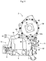
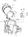
- a plurality of introduction fins 166 that are tilted in a posture for taking in outside air from the front side of the travelling machine body 102 in the advancing direction are arranged at a section of each opening hole 160 on the inner surface side of the hood 114.
- the plurality of introduction fins 166 are provided side by side at appropriate intervals back and forth in a tilted posture on the front side in the advancing direction while advancing from the right-and-left inner side to the right-and-left outer side, on the inner circumferential side of a mounting frame body 165 formed in a rectangular frame shape in such a manner as to surround the outer circumferential side of the opening hole 160.
- the mounting frame body 165 is screwed with a plurality of screws on the inner portion side of the hood 114 in such a manner as to insert each introduction fin 166 into the opening hole 160.
- a ventilating cover 161 made of perforated metal, wire gauze, and the like, which blocks the entry of scattering objects, is mounted on the inner surface side of the mounting frame body 165. The entry of the scattering objects such as dust is hampered with the ventilating cover 161. Also, the operator can be prevented from being in direct contact with the high-temperature exhaust gas purification device 2 by virtue of the existence of the plurality of introduction fins 166 and the ventilating cover 161.
- the industrial vehicle 101 includes the engine 1 mounted on the front portion of the travelling machine body 102 and the exhaust gas purification device 2 for purifying the exhaust gas of the engine 1, in which the exhaust gas purification device 2 is mounted on the upper portion side of the engine 1, and the engine 1 and the exhaust gas purification device 2 are covered with hood 114, and the maneuvering seat 117 is arranged on the rear side of the hood 114, and the opening holes 160 are formed on the right-and-left bilateral sides of the hood 114, and the introduction fin 166 that is tilted in a posture for taking in the outside air from the advancing direction is arranged in each opening hole 160, so that heat generated by the exhaust gas purification device 2 can be dissipated to the outside of the hood 114 by way of each opening hole 160 not only during the drive of the engine 1 but also after the stop of the engine 1, and the heat can be prevented from stagnating in the interior of the hood 114
- the introduction fin 166 arranged in each opening hole 160 is tilted in a posture for taking in the air from the front side of the travelling machine body 102 in the advancing direction, so that when the industrial vehicle 101 travels, the outside air is guided and introduced into the hood 114 by means of the introduction fin 166, and the ambient temperature of the exhaust gas purification device 2 can be prevented from increasing excessively. Also, after the stop of the engine 1, the discharge direction of the heat in the interior of the hood 114 is directed forward with respect to the maneuvering seat 117 by means of the introduction fin 166, thereby reducing the possibility of exposing the operator, who takes the maneuvering seat 117, to the heat.
- the transfer direction of the exhaust gas in the exhaust gas purification device 2 and the direction of the output shaft 3 of the engine 1 are set in parallel, and the transfer direction of the exhaust gas in the exhaust gas purification device 2 is along the back-and-forth direction of the hood 114, and the exhaust gas purification device 2 is arranged on one of the right and left sides near to the exhaust manifold 7 above the engine 1, so that when the exhaust gas purification device 2 faces one of the opening holes 160, the transfer direction of the exhaust gas in the exhaust gas purification device 2, that is, the longitudinal direction of the exhaust gas purification device 2 is along the back-and-forth direction of the hood 114, and the wide range of the outer circumferential surface of the exhaust gas purification device 2 can face one of the opening holes 160. Accordingly, the heat generated by the exhaust gas purification device 2 can be smoothly dissipated to the outside of the hood 114 by way of one of the opening holes 160.
- each opening hole 160 is formed on the beveling portion 158 that tilts obliquely downward while advancing from the right-and-left inner side to the right-and-left outer side, out of the right-and-left bilateral surfaces of the hood 114, and it is configured in such a manner that the exhaust gas purification device 2 does not protrude from one of the opening holes 160, so that while the heat generated by the exhaust gas purification device 2 is dissipated to the outside of the hood 114 after the stop of the engine 1, the scattering objects, for example, rainwater and dust can be prevented from falling on the exhaust gas purification device 2.
Landscapes
- Engineering & Computer Science (AREA)
- Chemical & Material Sciences (AREA)
- Combustion & Propulsion (AREA)
- Mechanical Engineering (AREA)
- General Engineering & Computer Science (AREA)
- Transportation (AREA)
- Materials Engineering (AREA)
- Health & Medical Sciences (AREA)
- Chemical Kinetics & Catalysis (AREA)
- Toxicology (AREA)
- Exhaust Gas After Treatment (AREA)
- Processes For Solid Components From Exhaust (AREA)
- Cooling, Air Intake And Gas Exhaust, And Fuel Tank Arrangements In Propulsion Units (AREA)
- Superstructure Of Vehicle (AREA)
Abstract
Description
- The present invention of the instant application relates to an industrial vehicle, such as a tractor, in which an exhaust gas purification device is mounted on the side of an upper portion of an engine, and the engine and the exhaust gas purification device are covered with a hood.
- These days, with the application of high-level emission control regarding diesel engines (hereinafter merely referred to an engine), it has been demanded that an exhaust gas purification device for purifying and treating air pollution substances in exhaust gas is mounted in agricultural work machines or construction work machines in which an engine is mounted. As the exhaust gas purification device, a diesel particulate filter (hereinafter referred to as DPF) for collecting particulate matter and the like in the exhaust gas has been known (for example, see Patent Literature 1).
- PTL I:
Japanese Unexamined Patent Application Publication No. 2008-31955 -
Patent Literature 1 discloses the structure of a tractor in which an engine is mounted in the front portion of a travelling machine body, and a front-to-back longitudinal DPF is arranged on one side of the right and left of an exhaust manifold above the engine and, and the engine along with the DPF is covered with a hood. In the tractor disclosed inPatent Literature 1, the DPF in the hood is further covered with a cover, which is aimed at suppressing an increase in temperature in the hood, but it is likely that heat stagnates and stays in the hood after the stop of the engine. Accordingly, there is a problem in that it is difficult to suppress the occurrence of heat damage on the DPF itself, the hood, and the like. - Accordingly, it is an object of the present invention to provide an industrial vehicle, in which improvements are provided in the light of the current circumstances.
- The present invention according to
claim 1 is such that an industrial vehicle includes an engine mounted on a front portion of a travelling machine body and an exhaust gas purification device for purifying exhaust gas of the engine, and the industrial vehicle is such that the exhaust gas purification device is mounted on an upper portion side of the engine, and the engine and the exhaust gas purification device are covered with a hood, and a maneuvering seat is arranged on a rear side of the hood, and the industrial vehicle includes opening holes configured to be formed on right and left bilateral surfaces of the hood, and an introduction fin that is configured to tilt in a posture for taking in outside air from a front side of the travelling machine body in an advancing direction is arranged in each opening hole. - Regarding the industrial vehicle described in
claim 1, the present invention according toclaim 2 is such that each opening hole is formed on a beveling portion that tilts obliquely downward while advancing from a right-and-left inner side to a right-and-left outer side, out of the right and left bilateral surfaces of the hood, and the exhaust gas purification device faces one of the opening holes when viewed from a lateral surface, and the exhaust gas purification device is configured not to protrude from one of the opening holes. - Regarding the industrial vehicle described in
claim 2, the present invention according toclaim 3 is such that a transfer direction of the exhaust gas in the exhaust gas purification device and a direction of an output shaft of the engine are set in parallel, and the transfer direction of the exhaust gas in the exhaust gas purification device is along a back-and-forth direction of the hood, and the exhaust gas purification device is arranged on one of right and left sides near to an exhaust manifold above the engine. - According to the present invention of the instant application, an industrial vehicle includes the engine mounted on a front portion of the travelling machine body and the exhaust gas purification device for purifying the exhaust gas of the engine, and the industrial vehicle is such that the exhaust gas purification device is mounted on the upper portion side of the engine, and the engine and the exhaust gas purification device are covered with the hood, and the maneuvering seat is arranged on the rear side of the hood, and the industrial vehicle includes the opening holes configured to be formed on the right and left bilateral sides of the hood, and the introduction fin that is configured to tilt in a posture for taking in the outside air from the front side of the travelling machine body in the advancing direction is arranged in each opening hole, so that the heat generated by the exhaust gas purification device can be dissipated to the outside of the hood by way of each opening hole not only during the drive of the engine but also after the stop of the engine, and the heat can be prevented from stagnating in the interior of the hood. As a result, the occurrence of heat damage on the exhaust gas purification device itself and the hood can be suppressed.
- In particular, the introduction fin arranged in each opening hole is tilted in a posture for taking in the air from the front side of the travelling machine body in the advancing direction, so that when the industrial vehicle travels, the outside air is guided and introduced into the hood by means of the introduction fin, and the ambient temperature of the exhaust gas purification device can be prevented from increasing excessively. Also, after the stop of the engine, the discharge direction of the heat in the interior of the hood is directed forward with respect to the maneuvering seat by means of the introduction fin, thereby reducing the possibility of exposing the operator, who takes the maneuvering seat, to the heat.
- According to the present invention of
claim 2, each opening hole is formed on the beveling portion that tilts obliquely downward while advancing from the right-and-left inner side to the right-and-left outer side, out of the right and left bilateral surfaces of the hood, and the exhaust gas purification device faces one of the opening holes when viewed from a lateral surface, and the exhaust gas purification device is configured not to protrude from one of the opening holes, so that while the heat generated by the exhaust gas purification device is dissipated to the outside of the hood after the stop of the engine, the scattering objects, for example, rainwater and dust can be prevented from falling on the exhaust gas purification device. - According to the present invention of
claim 3, the transfer direction of the exhaust gas in the exhaust gas purification device and the direction of the output shaft of the engine are set in parallel, and the transfer direction of the exhaust gas in the exhaust gas purification device is along the back-and-forth direction of the hood, and the exhaust gas purification device is arranged on one of the right and left sides near to the exhaust manifold above the engine, so that when the exhaust gas purification device faces one of the opening holes, the transfer direction of the exhaust gas in the exhaust gas purification device, that is, the longitudinal direction of the exhaust gas purification device is along the back-and-forth direction of the hood, and the wide range of the outer circumferential surface of the exhaust gas purification device can face one of the opening holes. Accordingly, the heat generated by the exhaust gas purification device can be smoothly dissipated to the outside of the hood by way of one of the opening holes. -
- [
Fig. 1] Fig. 1 is a left side view of a tractor in which an engine of an embodiment is mounted. - [
Fig. 2] Fig. 2 is a plan view of the tractor. - [
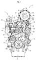
Fig. 3] Fig. 3 is a front view of the engine of the embodiment. - [
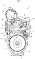
Fig. 4] Fig. 4 is a rear view of the engine. - [
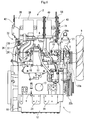
Fig. 5] Fig. 5 is a left side view of the engine. - [
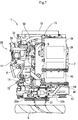
Fig. 6] Fig. 6 is a right side view of the engine. - [
Fig. 7] Fig. 7 is a plan view of the engine. - [
Fig. 8] Fig. 8 is a perspective view illustrating a positional relation of a cylinder head and an exhaust gas purification device when viewed from above on an obliquely left-front side. - [
Fig. 9] Fig. 9 is a perspective view illustrating a positional relation of the cylinder head and the exhaust gas purification device when viewed from above on an obliquely right-front side. - [
Fig. 10] Fig. 10 is a perspective view illustrating a positional relation of the cylinder head and the exhaust gas purification device when viewed from above on an obliquely right-rear side. - [
Fig. 11] Fig. 11 is a front view illustrating a mounting state of a bracket body and the exhaust gas purification device with respect to the cylinder head. - [
Fig. 12] Fig. 12 is a rear view illustrating a mounting state of the bracket body and the exhaust gas purification device with respect to the cylinder head. - [
Fig. 13] Fig. 13 is a separation perspective view of an inlet-side bracket body and an outlet-side bracket body. - [
Fig. 14] Fig. 14 is a separation perspective view of an extension bracket. - [
Fig. 15] Fig. 15 is a separation perspective view illustrating a mounting mode of the exhaust gas purification device, which is viewed from above on an obliquely right-front side. - [
Fig. 16] Fig. 16 is a separation perspective view illustrating the mounting mode of the exhaust gas purification device viewed from above on an obliquely right-rear side. - [
Fig. 17] Fig. 17 is a left side view to describe the internal structure of a hood. - [
Fig. 18] Fig. 18 is a right side view to describe the internal structure of the hood. - [
Fig. 19] Fig. 19 is a plan view to describe the internal structure of the hood. - [
Fig. 20] Fig. 20 is a cross-sectional front view illustrating a positional relation of the hood, the engine, and the exhaust gas purification device. - [
Fig. 21] Fig. 21 is a left side view to describe the structure of the external appearance of the hood. - Hereinafter, an embodiment, in which the present invention is embodied, will be described based on drawings. First, the structure in which an
engine 1 is mounted on atractor 101 as an industrial vehicle will be described referring toFigs. 1 and2 . In thetractor 101 of the embodiment, atravelling machine body 102 is supported withfront wheels 103 andrear wheels 104 arranged in the front and rear on the bilateral sides of the right and left thereof. Theengine 1 is mounted as a power engine in the front portion of thetravelling machine body 102. It is configured such that the power from theengine 1 causes the right and leftrear wheels 104 and the right and leftfront wheels 103 to rotate, thereby moving thetravelling machine body 102 forward and backward. The right and leftfront wheels 103 and the right and leftrear wheels 104 constitute the travelling portion of thetractor 101. - The
travelling machine body 102 includes anengine frame 108 that includes afront bumper 106 and afront axle case 107, aclutch housing 110 in which a main clutch for engaging/disengaging the transmission of the power from theengine 1 is incorporated, amission case 111 for appropriately shifting the power ofengine 1 and transmitting the power to the right and leftrear wheels 104 and the right and leftfront wheels 103, a missionfront surface case 112 that connects themission case 111 to theclutch housing 110, and a pair of right andleft step frames 113 that is directed outward and installed in a protruding manner on the outer side surface of theclutch housing 110. - A
radiator 109 for a coolant is arranged in the front of theengine 1. The rear end side of theengine frame 108 is coupled to the outer side surface of the right and left (specifically, engineleg mounting units 24 provided on an oil pan 12) of theengine 1. The front surface side of theclutch housing 110 is coupled to the rear surface side of aflywheel housing 10 of theengine 1. The front surface side of themission case 111 is coupled to the rear surface side of theclutch housing 110 via the missionfront surface case 112. - A
maneuvering seat 117 on which an operator sits and amaneuvering column 115 positioned in front of the maneuveringseat 117 are provided on the upper surface side of thetravelling machine body 102. Asteering wheel 116 is provided on the upper portion side of themaneuvering column 115. It is configured such that the operator who takes the maneuveringseat 117 manipulates and rotates the steering wheel, and the steering angle (steering angle) of the right and leftfront wheels 103 is changed in accordance with the rotational manipulated variable. - The
engine 1 is covered with ahood 114. Themaneuvering column 115 is vertically arranged on the upper surface side of theclutch housing 110. Thesteering wheel 116 for changing the steering angle (steering angle) of the right and leftfront wheels 103 through manipulation is provided on the upper surface side of themaneuvering column 115. Themaneuvering seat 117 on which the operator sits is arranged on the upper surface side of themission case 111. Aflat floor plate 118 is provided on the upper surface side of the right and left step frames 113. The right and leftfront wheels 103 are mounted on theengine frame 108 via thefront axle case 107. The right and leftrear wheels 104 are rotatably mounted on the right and left tip end sides of arear axle case 119 that protrudes outward from the outer side surface of themission case 111. The upper surface sides of the right and leftrear wheels 104 are covered withrear fenders 105. - A hydraulic hoisting and lowering
mechanism 120 for hoisting and lowering a work portion (not illustrated) of a rotary cultivator coupled to the rear portion of the travellingmachine body 102 is detachably mounted on the upper surface of the rear portion of themission case 111. APTO shaft 121 for transmitting a PTO drive force to the work portion is installed in a protruding manner on the rear surface of themission case 111. It is noted that the work portion is coupled to the rear portion of themission case 111 via a three-point linkage mechanism 124 made up of a pair of right and leftlower links 122 and onetop link 123. The right andleft lift arms 120a of the hydraulic hoisting and loweringmechanism 120 are coupled to the right and leftlower links 122 via alift rod 120b. The work portion is hoisted and lowered via the three-point linkage mechanism 124 by rotating upward and downward thelift arms 120a of the hydraulic hoisting and loweringmechanism 120. - A static hydraulic continuously variable transmission 125 (HST) is provided on the front surface side of the mission
front surface case 112. The static hydraulic continuously variable transmission 125 of the embodiment is incorporated in the rear portion of theclutch housing 110. Although details are omitted, the rotational power of the engine I is transmitted to the static hydraulic continuously variable transmission 125 by way of a main drive axle coupled to aflywheel 11 via the main clutch. Subsequently, the output from the static hydraulic continuously variable transmission 125 is appropriately shifted by an auxiliary transmission gear mechanism, and the shifted output is transmitted to the right and leftrear wheels 104 by way of a differential gear mechanism for rear wheels. The the shifted output that is appropriately shifted by the auxiliary transmission gear mechanism can be transmitted to the right and leftfront wheels 103 via a two-wheel-drive-and-four-wheel-drive switching mechanism and the differential gear mechanism in thefront axle case 107. In contrast, the rotational power by way of the main drive axle is transmitted to a PTO decelerating mechanism via a PTO transmission shaft, then appropriately decelerated by the PTO decelerating mechanism, and transmitted to thePTO shaft 121 via the PTO clutch. - As illustrated in
Figs. 1 and2 , aclutch pedal 131 is arranged to the left of themaneuvering column 115. An operator depresses theclutch pedal 131 with his foot, which actuates the main clutch in theclutch housing 110, and the transmission of the power from theengine 1 is blocked. A right-and-leftbrake pedal 132 for actuating respective brake mechanisms (not illustrated) for the control of the right and leftrear wheels 104 is arranged to the right of themaneuvering column 115. The brake mechanism is actuated by the operation of depressing thebrake pedal 132, and the right and leftrear wheels 104 are damped. It is noted that areverse lever 127 for switching a transfer direction to the forward or backward direction is arranged below thesteering wheel 116 and on the left of themaneuvering column 115. Anaccelerator lever 128 for changing the number of revolutions of theengine 1 is arranged below thesteering wheel 116 and on the right of themaneuvering column 115. - As illustrated in
Fig. 2 , a maingear shift lever 133 for shifting the static hydraulic continuously variable transmission 125 through manipulation is arranged on the right of themaneuvering seat 117. A work-portion hoisting-and-loweringlever 134 and a tilling-depth adjusting lever 135 are also arranged on the right of themaneuvering seat 117. Thelift arms 120a of the hydraulic hoisting and loweringmechanism 120 are rotated up and down by the manual operation of the work-portion hoisting-and-loweringlever 134 or the tilling-depth adjusting lever 135. An auxiliarygear shift lever 136 for switching the auxiliary transmission mechanism through manipulation is arranged on the left of themaneuvering seat 117. Each shift gear of the auxiliary transmission mechanism is selectively switched in three stages inclusive of a low speed position, a medium speed position, and a high speed position by the manual operation of the auxiliarygear shift lever 136. Neutral positions where auxiliary transmission output reaches zero are provided between the low speed position and the medium speed position, and between the medium speed position and the high speed position. Also, aPTO lever 137 for engaging/disengaging the transmission of the power to thePTO shaft 121 is arranged on the left of themaneuvering seat 117. - Subsequently, the schematic structure of the common-
rail engine 1 of the embodiment will be described referring toFigs. 3 to 7 . It is noted that, in the description below, the bilateral side portions (bilateral side portions sandwich an output shaft 3) along theoutput shaft 3 are referred to as "right-and-left", and the arrangement side of a coolingfan 9 is referred to as "front side", and the arrangement side of theflywheel 11 is referred to as "rear side", and the arrangement side of anexhaust manifold 7 is referred to as "left side", and the arrangement side of anintake manifold 6 is referred to as "right side", which serves as references for the four directions and the up-and-down positional relation regarding theengine 1 for convenience' sake. - As illustrated in
Figs. 3 to 7 , theengine 1 mounted on the industrial vehicle such as the tractor, as a power engine, includes a continuously regenerating exhaust gas purification device 2 (DPF). The particulate matter (PM) in the exhaust gas emitted from theengine 1 is removed by the exhaustgas purification device 2, and carbon monoxide (CO) or hydrogen carbon (HC) in the exhaust gas is reduced. - The
engine 1 includes acylinder block 4 in which the output shaft 3 (crankshaft) and pistons (not illustrated) are incorporated. Acylinder head 5 is mounted on thecylinder block 4. Theintake manifold 6 is arranged on the right lateral surface of thecylinder head 5. Theexhaust manifold 7 is arranged on the left lateral surface of thecylinder head 5. That is, theintake manifold 6 and theexhaust manifold 7 are allocated and arranged on the bilateral surfaces along theoutput shaft 3 in theengine 1. Ahead cover 8 is arranged on the upper surface of thecylinder head 5. The coolingfan 9 is provided on one side surface intersecting with theoutput shaft 3 in theengine 1, specifically, the front surface of thecylinder block 4. The rotational power is transmitted from the front end side of theoutput shaft 3 to the coolingfan 9 via aV belt 22a for the cooling fan. - The
flywheel housing 10 is provided on the rear surface of thecylinder block 4. Theflywheel 11 is arranged in theflywheel housing 10. Theflywheel 11 is pivotally supported on the rear end side of theoutput shaft 3. It is configured such that the power of theengine 1 is taken out to the work portion of the industrial vehicle via theoutput shaft 3. Also, anoil pan 12 is arranged on the lower surface of thecylinder block 4. Lubricating oil in theoil pan 12 is supplied to each lubricating portion of theengine 1 via anoil filter 13 arranged on the right lateral surface of thecylinder block 4. - A
fuel supply pump 14 for supplying fuel is mounted above the oil filter 13 (below the intake manifold 6) on the right lateral surface of thecylinder block 4.Injectors 15 for three cylinders, each of which includes a fuel injection valve (not illustrated) of an electromagnetic opening/closing control type, are provided in theengine 1. Eachinjector 15 is connected to a fuel tank (not illustrated) mounted on the industrial vehicle via thefuel supply pump 14, a cylindricalcommon rail 16, and afuel filter 17. - The fuel in the fuel tank is pressure-fed from the
fuel supply pump 14 to thecommon rail 16 via thefuel filter 17, and high-pressure fuel is accumulated in thecommon rail 16. The fuel injection valve of eachinjector 15 is controlled in such a manner as to be opened and closed, and the high-pressure fuel in thecommon rail 16 is injected from eachinjector 15 to each cylinder of theengine 1. It is noted that astarter 18 for starting the engine is provided in theflywheel housing 10. The pinion gear of thestarter 18 for starting the engine is meshed with a ring gear of theflywheel 11. When theengine 1 is started, the ring gear of theflywheel 11 is rotated by the rotational force of thestarter 18, which causes theoutput shaft 3 to start rotating (what is called cranking is executed). - A
coolant pump 21 is arranged coaxially with the fan shaft of the coolingfan 9 on the front surface side (the side of the cooling fan 9) of thecylinder head 5. As a generator, analternator 23 that generates electricity by use of the power of theengine 1 is provided on the left side of theengine 1, specifically, on the left side of thecoolant pump 21. The rotational power is transmitted from the front end side of theoutput shaft 3 to the coolingfan 9 and thecoolant pump 21 via theV belt 22a for the cooling fan. Also, the rotational power is transmitted from the front end side of theoutput shaft 3 to thealternator 23 via aV belt 22b for the alternator. The coolant in the radiator mounted on the industrial vehicle is supplied to thecylinder block 4 and thecylinder head 5 by means of the drive of thecoolant pump 21, thereby cooling theengine 1. - Engine
leg mounting units 24 are provided on the right and left lateral surfaces of theoil pan 12. In each engineleg mounting unit 24, an engine leg body (not illustrated) that includes a vibration-proof rubber can be fastened with bolts. In the embodiment, theoil pan 12 is clamped with a pair of right and left engine frames of the industrial vehicle, and the engineleg mounting unit 24 on the side of theoil pan 12 is fastened with bolts to each engine frame, so that the both engine frames of the industrial vehicle support theengine 1. - ] As illustrated in
Figs. 6 and7 , an air cleaner is coupled with the inlet portion of theintake manifold 6 via an EGR device 26 (exhaust gas recirculation device). TheEGR device 26 is mainly positioned on the right side of theengine 1, specifically, the right side of thecylinder head 5. After fresh air (outside air) drawn in by the air cleaner is purified by removing dust by means of the air cleaner, the fresh air is delivered to theintake manifold 6 via a compressor case 62 (its details are described later) of aturbo supercharger 60 and theEGR device 26 and supplied to each cylinder of theengine 1. - The
EGR device 26 includes an EGR main body case that mixes the part of the exhaust gas (EGR gas) of theengine 1 with the fresh air and supplies the mixed air to theintake manifold 6, anintake throttle member 28 through which the EGR main body case communicates with the air cleaner, a recirculationexhaust gas pipe 30 connected to theexhaust manifold 7 via anEGR cooler 29, and anEGR valve member 31 through which the EGR main body case communicates with the recirculationexhaust gas pipe 30. In the embodiment, the air intake side of theintake manifold 6 constitutes the EGR main body case. - That is, the
intake throttle member 28 is coupled with the air intake side of theintake manifold 6. Also, the outlet side of the recirculationexhaust gas pipe 30 is connected to the air intake side of theintake manifold 6. The inlet side of the recirculationexhaust gas pipe 30 is connected to theexhaust manifold 7 via theEGR cooler 29. The opening degree of the EGR valve in theEGR valve member 31 is adjusted, thereby adjusting the amount of EGR gas supplied to the air intake side of theintake manifold 6. - With the aforementioned constitution, the fresh air is supplied from the air cleaner into the air intake side of the
intake manifold 6 via theintake throttle member 28, whereas the EGR gas is supplied from theexhaust manifold 7 into the air intake side of theintake manifold 6. The fresh air from the air cleaner and the EGR gas from theexhaust manifold 7 are mixed in the air intake side of theintake manifold 6. Part of the exhaust gas discharged from theengine 1 to theexhaust manifold 7 is returned from theintake manifold 6 to theengine 1, so that the maximum combustion temperature during high-load operations is reduced, and the amount of NOx (nitride oxides) discharged from theengine 1 is reduced. - The
turbo supercharger 60 is arranged on the left side of thecylinder head 5 and above theexhaust manifold 7. Theturbo supercharger 60 includes aturbine case 61 in which a turbine wheel is incorporated, and acompressor case 62 in which a blower wheel is incorporated. The exhaust intake side of theturbine case 61 is coupled with the outlet portion of theexhaust manifold 7. Apurification inlet pipe 36 provided on an outer circumferential portion on the exhaust intake side of the exhaustgas purification device 2 is coupled with the exhaust discharge side of theturbine case 61. That is, the exhaust gas discharged from each cylinder of theengine 1 to theexhaust manifold 7 is released to the outside by way of theturbo supercharger 60, the exhaustgas purification device 2, and the like. - The air intake side of the
compressor case 62 is connected to the intake-air discharge side of the air cleaner via afeed pipe 65. The intake-air discharge side of thecompressor case 62 is connected to theintake manifold 6 via a superchargingpipe 66 and theEGR device 26. That is, the fresh air in which dust is removed by means of the air cleaner is transferred from thecompressor case 62 to theEGR device 26 via the superchargingpipe 66, and subsequently supplied to each cylinder of theengine 1. - The exhaust
gas purification device 2 is arranged above theexhaust manifold 7 and theturbo supercharger 60 on the upper surface side of theengine 1, that is, above theexhaust manifold 7 and theturbo supercharger 60 on the left side of thecylinder head 5. In this case, the posture of the exhaustgas purification device 2 is set in such a manner that the longitudinal direction of the exhaustgas purification device 2 extends in parallel to theoutput shaft 3 of theengine 1. - Next, the structure of the exhaust
gas purification device 2 will be described referring toFigs. 3 to 7 described above andFigs. 8 to 12 . The exhaustgas purification device 2 includes apurification housing 38 that includes thepurification inlet pipe 36. In the interior of thepurification housing 38, adiesel oxidation catalyst 39 such as platinum that generates nitrogen dioxide (NO2), and asoot filter 40 having honeycomb structure, in which the particulate matter (PM) collected is consecutively oxidized and removed at a relatively low temperature, are placed in series in the transfer direction of the exhaust gas. Thediesel oxidation catalyst 39 and thesoot filter 40 correspond to the exhaust gas purification device stored in thepurification housing 38. It is noted that theexhaust gas outlet 41 of thepurification housing 38 is coupled, for example, to a silencer or a tail pipe via an exhaust pipe, and the exhaust gas is discharged from theexhaust gas outlet 41 to the outside via the silencer or the tail pipe. - With the aforementioned constitution, the nitrogen dioxide (NO2) generated by the oxidation action of the
diesel oxidation catalyst 39 is taken into thesoot filter 40. The particulate matter included in the exhaust gas of theengine 1 is collected by thesoot filter 40, consecutively oxidized, and removed by the nitrogen dioxide (NO2). In addition to the removal of the particulate matter (PM) included in the exhaust gas of theengine 1, the content of carbon monoxide (CO) or hydrogen carbon (HC) in the exhaust gas of theengine 1 is reduced. - The
purification inlet pipe 36 is provided at the outer circumferential portion on the exhaust intake side of thepurification housing 38. The exhaust intake side of thepurification inlet pipe 36 is communicated with the exhaust discharge side of theturbine case 61. In this case, the lower end side of an inlet-sidesecond bracket 82 constituting a housing support body described later is fastened with bolts to theexhaust manifold 7. An exhaustjoint pipe 85 is formed as an exhaust joint path on the upper portion side of the inlet-sidesecond bracket 82. The exhaust intake side of the exhaustjoint pipe 85 is opened forward in an up-and-down midway portion of the inlet-sidesecond bracket 82. The exhaust discharge side of the exhaustjoint pipe 85 is opened upward on the upper end side of the inlet-sidesecond bracket 82. The exhaust intake side of the exhaustjoint pipe 85 in the inlet-sidesecond bracket 82 is fastened with bolts to the exhaust discharge side of theturbine case 61, and the exhaust discharge side of the exhaustjoint pipe 85 is fastened to the outlet portion of theexhaust manifold 7. Accordingly, theexhaust manifold 7 and the exhaustgas purification device 2 are communicated through the exhaustjoint pipe 85 of the inlet-sidesecond bracket 82. - A
lid body 42 is welded and fixed on the end portion on the exhaust downstream side of thepurification housing 38. The end portion on the exhaust downstream side of thepurification housing 38 is blocked with thelid body 42. Theexhaust gas outlet 41 is opened in an approximately central portion of thelid body 42. An inlet-side lid body 43 is welded and fixed on the end portion on the exhaust upstream side of thepurification housing 38. The end portion on the exhaust intake side of thepurification housing 38 is blocked with the inlet-side lid body 43. - Next, the structure in which the exhaust
gas purification device 2 is assembled with theengine 1 will be described referring toFigs. 8 to 16 . In theengine 1, an inlet-side bracket body 71 and an outlet-side bracket body 72 are provided as housing support bodies for supporting and fixing the exhaust gas purification device 2 (the purification housing 38). The inlet-side bracket body 71 and the outlet-side bracket body 72 are widely formed in the direction intersecting with theoutput shaft 3 of theengine 1. The inlet-side bracket body 71 and the outlet-side bracket body 72 are detachably coupled directly or through theintake manifold 6 or theexhaust manifold 7, to thecylinder head 5 of theengine 1. The inlet-side bracket body 71 and the outlet-side bracket body 72 are allocated to the front surface side and the rear surface side intersecting with theoutput shaft 3 in thecylinder head 5 and vertically arranged. The inlet-side bracket body 71 is positioned on the rear surface side of thecylinder head 5 and supports the exhaust intake side of thepurification housing 38. The outlet-side bracket body 72 is positioned on the front surface side of thecylinder head 5 and supports the exhaust discharge side of thepurification housing 38. - As illustrated in
Figs. 9, 10, 12 and 14 to 16 , the inlet-side bracket body 71 is positioned on the rear surface side (above the flywheel housing 10) of thecylinder head 5. The inlet-side bracket body 71 of the embodiment is configured to be separated into an inlet-sidefirst bracket 81 and an inlet-sidesecond bracket 82. The lower end side of the inlet-sidefirst bracket 81 is fastened with bolts to the rear surface of thecylinder head 5. Ajoint bracket 83 is fastened with bolts to the upper end side of the inlet-sidefirst bracket 81. The base end side of anextension bracket 84 is fastened with bolts to the midway portion of thejoint bracket 83, and the tip end side of theextension bracket 84 is fastened to the inlet-side lid body 43 of thepurification housing 38 via nuts and bolts. The lower end side of the inlet-sidesecond bracket 82 is fastened to theexhaust manifold 7 via nuts and bolts. The exhaust discharge side of the exhaustjoint pipe 85 formed on the upper portion side of the inlet-sidesecond bracket 82 is fastened to the outlet portion of theexhaust manifold 7. - As illustrated in
Figs. 8 to 13 and 15 , the outlet-side bracket body 72 is positioned on the front surface side (the side of the cooling fan 9) of thecylinder head 5. The outlet-side bracket body 72 of the embodiment is configured to be separated into an outlet-sidefirst bracket 91 and an outlet-sidesecond bracket 92. The outlet-sidefirst bracket 91 is an approximately L-shaped member that includes a longitudinalcylindrical portion 93 and alateral frame portion 94 extended sideways from the upper portion side of thecylindrical portion 93. The lower end side of thecylindrical portion 93 is fastened with bolts to the upper surface side of theintake manifold 6. The tip end side of thelateral frame portion 94 is fastened with bolts to the lateral side of the upper portion of the outlet-sidesecond bracket 92. The lower end side of the outlet-sidesecond bracket 92 is fastened with bolts to the front portion on the left lateral surface of thecylinder head 5. The upper end side of the outlet-sidesecond bracket 92 is fastened with bolts to abracket fastening portion 54a formed on the lower portion side of anoutlet clamping flange 54 in thepurification housing 38. Accordingly, the outlet-side bracket body 72 assumes an approximately portal shape on the front surface side of thecylinder head 5. - As is obvious in the aforementioned description, the exhaust gas purification device 2 (the purification housing 38) of the embodiment is detachably coupled with the
cylinder head 5, theintake manifold 6, and theexhaust manifold 7 of theengine 1 via the inlet-side bracket body 71 and the outlet-side bracket body 72, which are the housing support bodies, above theengine 1. Also, the inlet-side bracket body 71 (the inlet-sidefirst bracket 81 and the inlet-side second bracket 82) disposed on the upstream side (the exhaust intake side) of the transfer direction of the exhaust gas is allocated to thecylinder head 5 and theexhaust manifold 7, and the outlet-side bracket body 72 (the outlet-sidefirst bracket 91 and the outlet-side second bracket 92) disposed on the downstream side (the exhaust discharge side) of the transfer direction of the exhaust gas is allocated to thecylinder head 5 and theintake manifold 6, thereby supporting the exhaust gas purification device 2 (the purification housing 38) at four points. - As illustrated in
Figs. 11 and15 , an embeddedbolt 97 as a locking shaft body is provided on the central portion on the upper end side of the outlet-sidesecond bracket 92. The embeddedbolt 97 protrudes forward from the front surface of the central portion on the upper end side of the outlet-sidesecond bracket 92. Atemporary fixing notch 98 that is opened downward is formed in thebracket fastening portion 54a of theoutlet clamping flange 54 of thepurification housing 38. That is, a bolt hole for inserting the embeddedbolt 97 formed in thebracket fastening portion 54a of theoutlet clamping flange 54 is cut out upward in an open manner, so as to form thetemporary fixing notch 98. The embeddedbolt 97 of the outlet-sidesecond bracket 92 is lockably constituted in thetemporary fixing notch 98 of thebracket fastening portion 54a of theoutlet clamping flange 54. The downstream side (the exhaust discharge side) of the transfer direction of the exhaust gas in thepurification housing 38 is placed on the upper end side of the outlet-sidesecond bracket 92, and thetemporary fixing notch 98 is engaged with the embeddedbolt 97, which causes the outlet-sidesecond bracket 92 to support the downstream side (the exhaust discharge side) of the transfer direction of the exhaust gas in thepurification housing 38. - The exhaust discharge side of the
purification housing 38 is retained at a predetermined position by means of the engagement of the embeddedbolt 97 with thetemporary fixing notch 98. That is, thejoint bracket 83 mounted on thepurification housing 38 via theextension bracket 84 is placed on the upper end side of the inlet-sidefirst bracket 81, and the exhaust intake side of thepurification inlet pipe 36 is placed on the upper end side (the exhaust discharge side of the exhaust joint pipe 85) of the inlet-sidesecond bracket 82, and thetemporary fixing notch 98 on the side of thepurification housing 38 is engaged with the embeddedbolt 97 on the side of the outlet-sidesecond bracket 92, thereby temporarily fixing thepurification housing 38 on the inlet-side bracket body 71 and the outlet-side bracket body 72. Accordingly, the installation position of the exhaustgas purification device 2 with respect to theengine 1 can be simply determined, and an operator who performs an assembly work can detach both hands from the exhaustgas purification device 2 in a state of being temporarily fixed. Accordingly, it becomes unnecessary to carry out assembly works and disassembly works such as the fastening with bolts while supporting the entire weight of the exhaustgas purification device 2, so that much labor can be reduced during the loading and unloading works of the exhaustgas purification device 2 or during the assembly and disassembly works of the exhaustgas purification device 2. - Subsequently, the embedded
bolt 97 is screwed into (additionally tightened) a lockingnut 99 in a state where thetemporary fixing notch 98 is engaged with the embeddedbolt 97, and thebracket fastening portion 54a of theoutlet clamping flange 54 in thepurification housing 38 is coupled with the central portion on the upper end side of the outlet-sidesecond bracket 92. It is noted that, contrary to the embodiment, the embeddedbolt 97 may be provided on the side of thepurification housing 38, and thetemporary fixing notch 98 may be provided on the side of the outlet-sidesecond bracket 92. The opening direction of thetemporary fixing notch 98 only needs to be set in accordance with the positional relation to the embeddedbolt 97, but not limited to the shape opened downward. - As is obvious in the aforementioned description and
Figs. 8 to 16 , the engine device includes the exhaustgas purification device 2 that purifies the exhaust gas of theengine 1, in which the exhaustgas purification device 2 is mounted on theengine 1, and the plurality of housing support bodies 71 (81, 82) and 72 (91, 92) coupled with thepurification housing 38 constituting the exhaustgas purification device 2 are provided, and thepurification housing 38 is coupled with thecylinder head 5, theintake manifold 6, and theexhaust manifold 7 of theengine 1 via the group of the housing support bodies 71 (81, 82) and 72 (91, 92) above theengine 1, so that the exhaustgas purification device 2 can be supported with high rigidity as one constituent component of theengine 1, by use of thecylinder head 5, theintake manifold 6, and theexhaust manifold 7, which are the high-rigidity components of theengine 1, and the damage of the exhaustgas purification device 2 due to vibration and the like can be prevented. The exhaustgas purification device 2 is connected to theexhaust manifold 7 at point-blank range, high-temperature exhaust gas can be introduced to the exhaustgas purification device 2 at all times, and the exhaust gas purification capacity is easily maintained in a favorable state. - In particular, in the embodiment, the lower end sides of the inlet-side
first bracket 81 and the outlet-sidesecond bracket 92 are fastened to thecylinder head 5, so that the attachment reference position of the exhaustgas purification device 2 with respect to theengine 1 can be set with high accuracy. Accordingly, even when the weight of the exhaustgas purification device 2 is heavy, the exhaustgas purification device 2 can be appropriately mounted at a predetermined position, compared with a muffler which is an after-treatment device. - As is obvious in the aforementioned description and
Figs. 8 to 16 , thepurification housing 38 is arranged above theengine 1 in such a manner that the transfer direction of the exhaust gas in thepurification housing 38 and the direction of theoutput shaft 3 of theengine 1 are in parallel to each other, and the twohousing support bodies cylinder head 5 and theexhaust manifold 7, and the twohousing support bodies cylinder head 5 and theintake manifold 6, thereby supporting thepurification housing 38 at the four points, so that the exhaustgas purification device 2 can be mounted on theengine 1 with high rigidity via the group of the housing support bodies 71 (81, 82) and 72 (91, 92), and the effect of preventing the exhaustgas purification device 2 from vibrating can be improved. - As is obvious in the aforementioned description and
Figs. 8 to 16 , the exhaustjoint path 85 is formed in thehousing support body 82 coupled with theexhaust manifold 7, and theexhaust manifold 7 and the exhaustgas purification device 2 are communicated through the exhaustjoint path 85, so that thehousing support body 82 can be formed with the high rigidity while the exhaustgas purification device 2 can be simply connected to theexhaust manifold 7 at a short distance via the exhaustjoint path 85 of thehousing support body 82. - Next, the mounting structure of a
hood 114 will be described referring toFigs. 17 to 21 . Afront grille 138 is formed on the lower side of the front portion of thehood 114. The front, upper, right, and left sections of theengine 1 are covered with right and left engine covers 139 supported by theengine frame 108 and with thehood 114. Theradiator 109 mounted on the rear surface side of afan shroud 141 is vertically arranged on the frontal portion side of theengine frame 108 in such a manner as to be positioned on the frontal surface side of theengine 1. Thefan shroud 141 surrounds the outer circumferential side of the coolingfan 9, through which theradiator 109 communicates with the coolingfan 9. - A framed
frame 142 having a rectangular frame shape is vertically arranged on the front surface side of theradiator 109. Anoil cooler 143 for cooling the hydraulic oil in themission case 111 and abattery 144 for supply of power are arranged in the front of the framedframe 142. After cooling air blows against theoil cooler 143 and theradiator 109 by the rotation of the coolingfan 9, the cooling air flows to theengine 1 by way of thefan shroud 141. - An
air cleaner 145 for purifying the fresh air introduced to theengine 1 is arranged above theoil cooler 143 and thebattery 144 in the front of the framedframe 142. An intakejoint pipe 146 extended from one lateral surface of theair cleaner 145 is coupled with the inlet portion of theintake manifold 6 via theEGR device 26. A fresh air introduction pipe 147 for introducing the fresh air to theair cleaner 145 is formed on the outer circumferential surface of theair cleaner 145. - A
hood locking mechanism 151 for locking the lower side (the lower end side of the front grille 138) of the front portion of thehood 114 in a lockable manner is provided on the front end side (specifically, below the front grille 138) of theengine frame 108. It is configured such that thehood 114 is retained with thehood locking mechanism 151 in a posture of covering the frontal and upper spaces of theengine 1. A shieldingplate 152 for creating a partition between the side of theengine 1 and the side of themaneuvering column 115 is provided on the front surface side of themaneuvering column 115. The right and left engine covers 139, thehood 114, and theshielding plate 152 constitute anengine room 153 that surrounds the front, rear, right, left, and upper sections of theengine 1. - A back-and-forth longitudinal
upper support frame 154 is bridged between the upper portion on the rear surface of thefan shroud 141 and the upper portion on the front surface of theshielding plate 152. In contrast, a back-and-forthlongitudinal hood stay 155 is provided at a section opposite to theupper support frame 154 on the inner surface side of thehood 114. The rear end side of thehood stay 155 is vertically rotatably mounted on theshielding plate 152 via a hood opening/closing fulcrum shaft 156. Agas damper 157 is mounted between theupper support frame 154 and thehood stay 155. The end portion on the side of the rod of thegas damper 157 is pivotally fitted to the front portion side of the upper support frame in a rotatable manner by means of a pin shaft disposed sideways in the right-and-left direction. The end portion on the side of the cylinder of thegas damper 157 is pivotally fitted to a back-and-forth midway portion of thehood stay 155 in a rotatable manner by means of the pin shaft disposed sideways in the right-and-left direction. After the operation of releasing the locking of thehood locking mechanism 151 is performed, the front portion of thehood 114 is raised forward, thereby rotating thehood 114 upward about the hood opening/closing fulcrum shaft 156 and opening the frontal and upper spaces of theengine 1. Then, thehood 114 is maintained at an open position by the prop-up action of thegas damper 157. - As illustrated in
Figs. 17 to 20 , theengine 1 of the embodiment is longitudinally mounted on the front side of the travellingmachine body 102 in a state where the coolingfan 9 is positioned on the front side, and theflywheel housing 10 is positioned on the rear side. That is, theengine 1 is mounted on the front side of the travellingmachine body 102 in such a manner that the direction of theoutput shaft 3 is along the advancing direction of the travellingmachine body 102. The longitudinal direction (the transfer direction of the exhaust gas in the purification housing 38) of the exhaustgas purification device 2 is parallel to theoutput shaft 3, so that the exhaust gas purification device 2 (the purification housing 38) is arranged near to theexhaust manifold 7 above theengine 1 in a longitudinally mounted posture extended along the advancing direction (the back-and-forth direction) of the travellingmachine body 102. - As illustrated in
Fig. 20 , thehood 114 of thetractor 101 is formed in such a manner that its cross section is an inverted U-shape. The right and left corner portions of thehood 114 are provided asbeveling portions 158 that are beveled in such a manner as to tilt obliquely downward on the outer sides of the right and left thereof when viewed from the front surface. The right and left corner portions of thehood 114 are constituted as thebeveling portions 158, thereby favorably securing the front view of an operator who sits on themaneuvering seat 117, in particular, a view ahead of the right and leftbeveling portions 158 of thehood 114. Then, the exhaustgas purification device 2 faces the inner surface side of theleft beveling portion 158 of thehood 114. - The exhaust
gas purification device 2 is offset near to the center (see a perpendicular virtual line L orthogonal to theoutput shaft 3 of the engine 1) of the right-and-left width Wz of theengine 1, in order to prevent the exhaustgas purification device 2 from protruding from theengine 1 in the right-and-left direction. The exhaustgas purification device 2 stays within the right-and-left width Wz in the right-and-left direction orthogonal to theoutput shaft 3 of theengine 1. In the embodiment, the right-and-left width Wa of the exhaustgas purification device 2 is made smaller than a distance Wy from the center of the right-and-left width Wz of theengine 1 to the outermost portion of the right-and-left width Wz. That is, the right-and-left width Wa of the exhaustgas purification device 2 is made smaller than the distance Wy (which corresponds to an approximately half of the right-and-left width Wz of the engine 1) from the perpendicular virtual line L to the outermost portion of thealternator 23. Also, the exhaustgas purification device 2 stays within a back-and-forth width Wx in the back-and-forth direction along theoutput shaft 3 of theengine 1 when viewed from a plane. That is, a back-and-forth width Wb of the exhaustgas purification device 2 is made smaller than the back-and-forth width Wx (a distance from the coolingfan 9 to the flywheel housing 10) of theengine 1. - As is obvious in the aforementioned description and
Figs. 1, 2 and 17 to 21 , the engine device mounted on the tractor 101 that includes the engine 1 that is mounted on the travelling machine body 102 and covered with the hood 114 is such that when the exhaust gas purification device 2 for purifying the exhaust gas of the engine 1 is arranged on one of the right-and-left sides near to the exhaust manifold 7 above the engine 1, the transfer direction of the exhaust gas in the exhaust gas purification device 2 is set in parallel to the direction of the output shaft 3 of the engine 1, and the exhaust gas purification device 2 is offset near to the center of the right-and-left width Wz of the engine 1, in order to prevent the exhaust gas purification device 2 from protruding from the engine 1, and the right-and-left width Wa of the exhaust gas purification device 2 is made smaller than the distance Wy from the center of the right-and-left width Wz of the engine 1 to the outermost portion of the right-and-left width Wz, so that the upper space of the engine 1 is efficiently used, without providing the outward projecting portions of the right-and-left corner portions of the hood found in conventional technologies, and the exhaust gas purification device 2 can be stored in a limited space between the upper portion of the engine 1 and the inner surface of the hood 114. Also, the outward projecting portions of thehood 114, which blocks the view of the operator, can be eliminated, thereby contributing to the improvement of the forward visibility of thetractor 101. Furthermore, the exhaustgas purification device 2, which is a heavy object, is brought close to the center of gravity of theengine 1 and supported, so that an increase in the vibration or noise of theengine 1, which is attributed to the installation of the exhaustgas purification device 2, can be suppressed. - As is obvious in the aforementioned description and
Figs. 1, 2 and 17 to 19 , the back-and-forth width Wb of the exhaustgas purification device 2 stays within the back-and-forth width Wx of theengine 1 viewed from a plane, so that even when theengine 1 is assembled with the exhaustgas purification device 2, the structure in which the entire widths of the back, front, right, and left are reduced as much as possible can be provided, which is contributed to the miniaturization as the whole of the engine device. The influence on the shape of thehood 114 due to the assembly of the exhaustgas purification device 2 on theengine 1 can be alleviated, and the complication of the shape of thehood 114 can be avoided. - As illustrated in
Fig. 20 in detail, openingholes 160 are formed on the right-and-left bilateral sides of thehood 114. The exhaustgas purification device 2 faces the one of the right and left opening holes 160. In the embodiment, eachopening hole 160 is formed on thebeveling portion 158 that is tilted obliquely downward from the right-and-left inner side to the right-and-left outer side, out of the right-and-left bilateral surfaces of thehood 114. Each opening hole is made smaller than the shape of the exhaustgas purification device 2 viewed from a lateral surface, and it is configured in such a manner that the exhaustgas purification device 2 does not protrude from theleft opening hole 160 facing the exhaustgas purification device 2. - A plurality of
introduction fins 166 that are tilted in a posture for taking in outside air from the front side of the travellingmachine body 102 in the advancing direction are arranged at a section of eachopening hole 160 on the inner surface side of thehood 114. In this case, the plurality ofintroduction fins 166 are provided side by side at appropriate intervals back and forth in a tilted posture on the front side in the advancing direction while advancing from the right-and-left inner side to the right-and-left outer side, on the inner circumferential side of a mountingframe body 165 formed in a rectangular frame shape in such a manner as to surround the outer circumferential side of theopening hole 160. Then, the mountingframe body 165 is screwed with a plurality of screws on the inner portion side of thehood 114 in such a manner as to insert eachintroduction fin 166 into theopening hole 160. Aventilating cover 161 made of perforated metal, wire gauze, and the like, which blocks the entry of scattering objects, is mounted on the inner surface side of the mountingframe body 165. The entry of the scattering objects such as dust is hampered with theventilating cover 161. Also, the operator can be prevented from being in direct contact with the high-temperature exhaustgas purification device 2 by virtue of the existence of the plurality ofintroduction fins 166 and theventilating cover 161. - As is obvious in the aforementioned description and
Figs. 15 ,16 ,20 , and21 , theindustrial vehicle 101 includes theengine 1 mounted on the front portion of the travellingmachine body 102 and the exhaustgas purification device 2 for purifying the exhaust gas of theengine 1, in which the exhaustgas purification device 2 is mounted on the upper portion side of theengine 1, and theengine 1 and the exhaustgas purification device 2 are covered withhood 114, and themaneuvering seat 117 is arranged on the rear side of thehood 114, and the opening holes 160 are formed on the right-and-left bilateral sides of thehood 114, and theintroduction fin 166 that is tilted in a posture for taking in the outside air from the advancing direction is arranged in eachopening hole 160, so that heat generated by the exhaustgas purification device 2 can be dissipated to the outside of thehood 114 by way of eachopening hole 160 not only during the drive of theengine 1 but also after the stop of theengine 1, and the heat can be prevented from stagnating in the interior of thehood 114. As a result, the occurrence of heat damage on the exhaustgas purification device 2 itself and thehood 114 can be suppressed. - In particular, the
introduction fin 166 arranged in eachopening hole 160 is tilted in a posture for taking in the air from the front side of the travellingmachine body 102 in the advancing direction, so that when theindustrial vehicle 101 travels, the outside air is guided and introduced into thehood 114 by means of theintroduction fin 166, and the ambient temperature of the exhaustgas purification device 2 can be prevented from increasing excessively. Also, after the stop of theengine 1, the discharge direction of the heat in the interior of thehood 114 is directed forward with respect to themaneuvering seat 117 by means of theintroduction fin 166, thereby reducing the possibility of exposing the operator, who takes themaneuvering seat 117, to the heat. - As is obvious in the aforementioned description and
Fig. 20 , the transfer direction of the exhaust gas in the exhaustgas purification device 2 and the direction of theoutput shaft 3 of theengine 1 are set in parallel, and the transfer direction of the exhaust gas in the exhaustgas purification device 2 is along the back-and-forth direction of thehood 114, and the exhaustgas purification device 2 is arranged on one of the right and left sides near to theexhaust manifold 7 above theengine 1, so that when the exhaustgas purification device 2 faces one of the opening holes 160, the transfer direction of the exhaust gas in the exhaustgas purification device 2, that is, the longitudinal direction of the exhaustgas purification device 2 is along the back-and-forth direction of thehood 114, and the wide range of the outer circumferential surface of the exhaustgas purification device 2 can face one of the opening holes 160. Accordingly, the heat generated by the exhaustgas purification device 2 can be smoothly dissipated to the outside of thehood 114 by way of one of the opening holes 160. - As is obvious in the aforementioned description and
Fig. 20 , eachopening hole 160 is formed on thebeveling portion 158 that tilts obliquely downward while advancing from the right-and-left inner side to the right-and-left outer side, out of the right-and-left bilateral surfaces of thehood 114, and it is configured in such a manner that the exhaustgas purification device 2 does not protrude from one of the opening holes 160, so that while the heat generated by the exhaustgas purification device 2 is dissipated to the outside of thehood 114 after the stop of theengine 1, the scattering objects, for example, rainwater and dust can be prevented from falling on the exhaustgas purification device 2. - It is noted that the constitution of each portion of the present invention of the instant application is not limited to the embodiments illustrated, but various modifications can be applied without departing from the scope of the gist of the present invention of the instant application.
-
- 1
- Engine
- 2
- Exhaust gas purification device
- 3
- Output shaft
- 4
- Cylinder block
- 5
- Cylinder head
- 6
- Intake manifold
- 7
- Exhaust manifold
- 8
- Head cover
- 9
- Cooling fan
- 71
- Inlet-side bracket body
- 72
- Outlet-side bracket body
- 81
- First lifting metal tool
- 82
- Second lifting metal tool
- 91
- Outlet-side first bracket
- 92
- Outlet-side second bracket
- 97
- Embedded bolt
- 98
- Temporary fixing notch
- 101
- Tractor
- 102
- Travelling machine body
- 114
- Hood
- 158
- Beveling portion
- 160
- Opening hole
- 161
- Ventilating cover
- 165
- Mounting frame body
- 166
- Introduction fin
Claims (3)
- An industrial vehicle configured to include an engine mounted on a front portion of a travelling machine body and an exhaust gas purification device for purifying exhaust gas of the engine, and the industrial vehicle is such that the exhaust gas purification device is mounted on an upper portion side of the engine, and the engine and the exhaust gas purification device are covered with a hood, and a maneuvering seat is arranged on a rear side of the hood, comprising:opening holes configured to be formed on right and left bilateral surfaces of the hood,wherein an introduction fin configured to tilt in a posture for taking in outside air from a front side of the travelling machine body in an advancing direction is arranged in each opening hole.
- The industrial vehicle according to claim 1,
wherein each opening hole is formed on a beveling portion that tilts obliquely downward while advancing from a right-and-left inner side to a right-and-left outer side, out of the right and left bilateral surfaces of the hood, and
wherein the exhaust gas purification device faces one of the opening holes when viewed from a lateral surface, and
wherein the exhaust gas purification device is configured not to protrude from one of the opening holes. - The industrial vehicle according to claim 2,
wherein a transfer direction of the exhaust gas in the exhaust gas purification device and a direction of an output shaft of the engine are set in parallel, and
wherein the transfer direction of the exhaust gas in the exhaust gas purification device is along a back-and-forth direction of the hood, and
wherein the exhaust gas purification device is arranged on one of right and left sides near to an exhaust manifold above the engine.
Applications Claiming Priority (2)
| Application Number | Priority Date | Filing Date | Title |
|---|---|---|---|
| JP2013125804A JP6120689B2 (en) | 2013-06-14 | 2013-06-14 | Tractor |
| PCT/JP2014/065472 WO2014200021A1 (en) | 2013-06-14 | 2014-06-11 | Industrial vehicle |
Publications (3)
| Publication Number | Publication Date |
|---|---|
| EP3009334A1 true EP3009334A1 (en) | 2016-04-20 |
| EP3009334A4 EP3009334A4 (en) | 2017-01-18 |
| EP3009334B1 EP3009334B1 (en) | 2019-09-04 |
Family
ID=52022312
Family Applications (1)
| Application Number | Title | Priority Date | Filing Date |
|---|---|---|---|
| EP14811049.7A Active EP3009334B1 (en) | 2013-06-14 | 2014-06-11 | Industrial vehicle |
Country Status (6)
| Country | Link |
|---|---|
| US (1) | US9944168B2 (en) |
| EP (1) | EP3009334B1 (en) |
| JP (1) | JP6120689B2 (en) |
| KR (3) | KR102128238B1 (en) |
| CN (1) | CN105283372B (en) |
| WO (1) | WO2014200021A1 (en) |
Cited By (2)
| Publication number | Priority date | Publication date | Assignee | Title |
|---|---|---|---|---|
| EP3208439A4 (en) * | 2014-10-15 | 2017-12-13 | Yanmar Co., Ltd. | Engine device |
| EP3974584A1 (en) * | 2020-09-28 | 2022-03-30 | Kubota Corporation | Work vehicle |
Families Citing this family (17)
| Publication number | Priority date | Publication date | Assignee | Title |
|---|---|---|---|---|
| JP5882158B2 (en) * | 2012-07-26 | 2016-03-09 | ヤンマー株式会社 | Engine equipment |
| JP5676827B1 (en) * | 2013-08-09 | 2015-02-25 | 株式会社小松製作所 | Support mechanism, exhaust treatment unit, wheel loader |
| EP2985166B1 (en) * | 2014-08-14 | 2017-08-02 | CNH Industrial Italia S.p.A. | Exhaust system for an off-road vehicle |
| JP6438341B2 (en) * | 2014-10-15 | 2018-12-12 | ヤンマー株式会社 | Work vehicle |
| JP6400520B2 (en) * | 2015-03-30 | 2018-10-03 | 株式会社クボタ | Working machine |
| JP6475569B2 (en) * | 2015-05-22 | 2019-02-27 | ヤンマー株式会社 | Engine equipment |
| EP3299263B1 (en) * | 2015-05-22 | 2021-09-01 | Yanmar Power Technology Co., Ltd. | Method of assembling a tractor |
| WO2017022217A1 (en) * | 2015-07-31 | 2017-02-09 | ヤンマー株式会社 | Work vehicle |
| JP2017030520A (en) * | 2015-07-31 | 2017-02-09 | ヤンマー株式会社 | Tractor |
| JP6448507B2 (en) | 2015-10-20 | 2019-01-09 | ヤンマー株式会社 | Work vehicle |
| US9914487B2 (en) * | 2015-11-06 | 2018-03-13 | Kubota Corporation | Work vehicle |
| JP6657134B2 (en) * | 2017-03-14 | 2020-03-04 | ヤンマー株式会社 | Tractor |
| JP6731876B2 (en) * | 2017-03-24 | 2020-07-29 | ヤンマーパワーテクノロジー株式会社 | Engine equipment |
| JP6679676B2 (en) * | 2018-09-05 | 2020-04-15 | 株式会社クボタ | Work machine |
| US12215612B2 (en) * | 2020-12-03 | 2025-02-04 | Transportation Ip Holdings, Llc | System and method for a cab-mounted muffler assembly |
| CN114837787B (en) * | 2022-05-24 | 2023-05-26 | 河南职业技术学院 | Automobile exhaust emission purification device |
| US12071015B2 (en) * | 2022-12-22 | 2024-08-27 | Martin Sheet Metal, Inc. | Combined motor and compressor mount for lift truck |
Family Cites Families (26)
| Publication number | Priority date | Publication date | Assignee | Title |
|---|---|---|---|---|
| US959571A (en) | 1908-07-18 | 1910-05-31 | Wilson P Mays | Hood for motor-vehicles. |
| US1081050A (en) | 1913-02-24 | 1913-12-09 | Bliss E W Co | Sheet-metal-working machine. |
| CH173950A (en) | 1934-02-21 | 1934-12-15 | Tatra Werke Ag | Air cooling device on motor vehicles with preferably air-cooled rear engine. |
| DE881611C (en) | 1941-01-17 | 1953-07-02 | Suedwerke Motoren Und Kraftwag | Cooling air supply for vehicles with air-cooled rear engine |
| US2529994A (en) * | 1942-10-27 | 1950-11-14 | Tatra Np | Air inlet structure for rear engine compartments of streamlined vehicles |
| JPS51119407U (en) * | 1975-03-25 | 1976-09-28 | ||
| US4081050A (en) * | 1977-02-02 | 1978-03-28 | International Harvester Company | Front engine tractor having transverse midship mounted heat exchanger |
| FR2637549B1 (en) * | 1988-10-07 | 1993-05-21 | Kubota Ltd | COOLING SYSTEM FOR A VEHICLE MOUNTED ENGINE |
| US5678649A (en) * | 1993-09-28 | 1997-10-21 | Kubota Corporation | Steering console for a working vehicle |
| JP2002021565A (en) * | 2000-07-11 | 2002-01-23 | Komatsu Ltd | Construction vehicle engine enclosure |
| JP3801475B2 (en) * | 2001-09-21 | 2006-07-26 | 株式会社クボタ | Air intake structure for lawn mower cooling |
| US7213667B2 (en) * | 2004-10-29 | 2007-05-08 | Deere & Company | Air intake |
| JP2008031955A (en) | 2006-07-31 | 2008-02-14 | Iseki & Co Ltd | diesel engine |
| JP2010030472A (en) * | 2008-07-29 | 2010-02-12 | Kobelco Contstruction Machinery Ltd | Cooling device of construction equipment |
| JP5184387B2 (en) * | 2009-01-09 | 2013-04-17 | ヤンマー株式会社 | Bonnet structure |
| JP5296560B2 (en) * | 2009-01-09 | 2013-09-25 | ヤンマー株式会社 | Bonnet structure |
| JP5435965B2 (en) * | 2009-01-15 | 2014-03-05 | ヤンマー株式会社 | Tractor |
| JP2010215122A (en) * | 2009-03-17 | 2010-09-30 | Hitachi Constr Mach Co Ltd | Engine cover for construction machine |
| JP5189041B2 (en) * | 2009-07-17 | 2013-04-24 | 住友建機株式会社 | Hybrid construction machine |
| WO2011027446A1 (en) | 2009-09-03 | 2011-03-10 | 本田技研工業株式会社 | Cooling structure for radiator for water-cooled power unit |
| JP2011088607A (en) * | 2009-10-26 | 2011-05-06 | Iseki & Co Ltd | Working vehicle |
| JP2011126488A (en) * | 2009-12-21 | 2011-06-30 | Iseki & Co Ltd | Working vehicle |
| US20120125271A1 (en) * | 2010-11-23 | 2012-05-24 | Caterpillar Inc. | Engine system with air diverter |
| JP5508351B2 (en) * | 2011-06-30 | 2014-05-28 | 日立建機株式会社 | Work machine |
| JP5911392B2 (en) * | 2012-07-20 | 2016-04-27 | 株式会社クボタ | Work vehicle |
| CN104302884B (en) * | 2013-03-29 | 2016-08-24 | 株式会社小松制作所 | exhaust treatment unit |
-
2013
- 2013-06-14 JP JP2013125804A patent/JP6120689B2/en active Active
-
2014
- 2014-06-11 KR KR1020157032352A patent/KR102128238B1/en active Active
- 2014-06-11 WO PCT/JP2014/065472 patent/WO2014200021A1/en not_active Ceased
- 2014-06-11 KR KR1020207018171A patent/KR20200078699A/en not_active Ceased
- 2014-06-11 KR KR1020217022592A patent/KR20210092849A/en not_active Ceased
- 2014-06-11 EP EP14811049.7A patent/EP3009334B1/en active Active
- 2014-06-11 CN CN201480033705.1A patent/CN105283372B/en not_active Expired - Fee Related
- 2014-06-11 US US14/893,259 patent/US9944168B2/en active Active
Cited By (4)
| Publication number | Priority date | Publication date | Assignee | Title |
|---|---|---|---|---|
| EP3208439A4 (en) * | 2014-10-15 | 2017-12-13 | Yanmar Co., Ltd. | Engine device |
| US10669913B2 (en) | 2014-10-15 | 2020-06-02 | Yanmar Co., Ltd. | Engine apparatus |
| US12228063B2 (en) | 2014-10-15 | 2025-02-18 | Yanmar Power Technology Co., Ltd. | Engine apparatus |
| EP3974584A1 (en) * | 2020-09-28 | 2022-03-30 | Kubota Corporation | Work vehicle |
Also Published As
| Publication number | Publication date |
|---|---|
| KR20160021089A (en) | 2016-02-24 |
| EP3009334A4 (en) | 2017-01-18 |
| JP6120689B2 (en) | 2017-04-26 |
| JP2015000636A (en) | 2015-01-05 |
| CN105283372A (en) | 2016-01-27 |
| US9944168B2 (en) | 2018-04-17 |
| KR20210092849A (en) | 2021-07-26 |
| WO2014200021A1 (en) | 2014-12-18 |
| KR20200078699A (en) | 2020-07-01 |
| KR102128238B1 (en) | 2020-06-30 |
| US20160096426A1 (en) | 2016-04-07 |
| CN105283372B (en) | 2018-09-04 |
| EP3009334B1 (en) | 2019-09-04 |
Similar Documents
| Publication | Publication Date | Title |
|---|---|---|
| EP3009334B1 (en) | Industrial vehicle | |
| JP6192576B2 (en) | Engine equipment | |
| KR102089930B1 (en) | Working vehicle | |
| EP3098411A1 (en) | Engine device | |
| KR102136917B1 (en) | Engine device | |
| WO2015093375A1 (en) | Working vehicle | |
| KR102227899B1 (en) | Work vehicle | |
| JP2014145266A (en) | Engine device and tractor mounted with the same | |
| WO2015147232A1 (en) | Work vehicle | |
| JP2010216389A (en) | Engine device to be mounted on work vehicle | |
| JP5892959B2 (en) | Work vehicle | |
| JP6216164B2 (en) | Work vehicle | |
| JP5961562B2 (en) | Engine device and tractor equipped with the same | |
| JP2010216332A (en) | Engine and engine device | |
| CN106103172B (en) | work vehicle | |
| JP6233963B2 (en) | Engine equipment | |
| JP2015189395A (en) | work vehicle | |
| JP6129733B2 (en) | Engine equipment | |
| JP2016217210A (en) | Engine device | |
| JP2015101997A (en) | Engine apparatus | |
| JP2015189394A (en) | work vehicle |
Legal Events
| Date | Code | Title | Description |
|---|---|---|---|
| PUAI | Public reference made under article 153(3) epc to a published international application that has entered the european phase |
Free format text: ORIGINAL CODE: 0009012 |
|
| 17P | Request for examination filed |
Effective date: 20151203 |
|
| AK | Designated contracting states |
Kind code of ref document: A1 Designated state(s): AL AT BE BG CH CY CZ DE DK EE ES FI FR GB GR HR HU IE IS IT LI LT LU LV MC MK MT NL NO PL PT RO RS SE SI SK SM TR |
|
| AX | Request for extension of the european patent |
Extension state: BA ME |
|
| DAX | Request for extension of the european patent (deleted) | ||
| A4 | Supplementary search report drawn up and despatched |
Effective date: 20161219 |
|
| RIC1 | Information provided on ipc code assigned before grant |
Ipc: B60K 13/04 20060101ALI20161213BHEP Ipc: F01N 3/02 20060101ALI20161213BHEP Ipc: B62D 25/10 20060101AFI20161213BHEP Ipc: F01N 3/28 20060101ALI20161213BHEP |
|
| GRAP | Despatch of communication of intention to grant a patent |
Free format text: ORIGINAL CODE: EPIDOSNIGR1 |
|
| STAA | Information on the status of an ep patent application or granted ep patent |
Free format text: STATUS: GRANT OF PATENT IS INTENDED |
|
| INTG | Intention to grant announced |
Effective date: 20190429 |
|
| GRAS | Grant fee paid |
Free format text: ORIGINAL CODE: EPIDOSNIGR3 |
|
| GRAA | (expected) grant |
Free format text: ORIGINAL CODE: 0009210 |
|
| STAA | Information on the status of an ep patent application or granted ep patent |
Free format text: STATUS: THE PATENT HAS BEEN GRANTED |
|
| AK | Designated contracting states |
Kind code of ref document: B1 Designated state(s): AL AT BE BG CH CY CZ DE DK EE ES FI FR GB GR HR HU IE IS IT LI LT LU LV MC MK MT NL NO PL PT RO RS SE SI SK SM TR |
|
| REG | Reference to a national code |
Ref country code: GB Ref legal event code: FG4D |
|
| REG | Reference to a national code |
Ref country code: CH Ref legal event code: EP |
|
| REG | Reference to a national code |
Ref country code: AT Ref legal event code: REF Ref document number: 1174959 Country of ref document: AT Kind code of ref document: T Effective date: 20190915 |
|
| REG | Reference to a national code |
Ref country code: DE Ref legal event code: R096 Ref document number: 602014053084 Country of ref document: DE |
|
| REG | Reference to a national code |
Ref country code: IE Ref legal event code: FG4D |
|
| REG | Reference to a national code |
Ref country code: NL Ref legal event code: MP Effective date: 20190904 |
|
| REG | Reference to a national code |
Ref country code: LT Ref legal event code: MG4D |
|
| PG25 | Lapsed in a contracting state [announced via postgrant information from national office to epo] |
Ref country code: NO Free format text: LAPSE BECAUSE OF FAILURE TO SUBMIT A TRANSLATION OF THE DESCRIPTION OR TO PAY THE FEE WITHIN THE PRESCRIBED TIME-LIMIT Effective date: 20191204 Ref country code: LT Free format text: LAPSE BECAUSE OF FAILURE TO SUBMIT A TRANSLATION OF THE DESCRIPTION OR TO PAY THE FEE WITHIN THE PRESCRIBED TIME-LIMIT Effective date: 20190904 Ref country code: BG Free format text: LAPSE BECAUSE OF FAILURE TO SUBMIT A TRANSLATION OF THE DESCRIPTION OR TO PAY THE FEE WITHIN THE PRESCRIBED TIME-LIMIT Effective date: 20191204 Ref country code: FI Free format text: LAPSE BECAUSE OF FAILURE TO SUBMIT A TRANSLATION OF THE DESCRIPTION OR TO PAY THE FEE WITHIN THE PRESCRIBED TIME-LIMIT Effective date: 20190904 Ref country code: HR Free format text: LAPSE BECAUSE OF FAILURE TO SUBMIT A TRANSLATION OF THE DESCRIPTION OR TO PAY THE FEE WITHIN THE PRESCRIBED TIME-LIMIT Effective date: 20190904 Ref country code: SE Free format text: LAPSE BECAUSE OF FAILURE TO SUBMIT A TRANSLATION OF THE DESCRIPTION OR TO PAY THE FEE WITHIN THE PRESCRIBED TIME-LIMIT Effective date: 20190904 |
|
| PG25 | Lapsed in a contracting state [announced via postgrant information from national office to epo] |
Ref country code: ES Free format text: LAPSE BECAUSE OF FAILURE TO SUBMIT A TRANSLATION OF THE DESCRIPTION OR TO PAY THE FEE WITHIN THE PRESCRIBED TIME-LIMIT Effective date: 20190904 Ref country code: GR Free format text: LAPSE BECAUSE OF FAILURE TO SUBMIT A TRANSLATION OF THE DESCRIPTION OR TO PAY THE FEE WITHIN THE PRESCRIBED TIME-LIMIT Effective date: 20191205 Ref country code: AL Free format text: LAPSE BECAUSE OF FAILURE TO SUBMIT A TRANSLATION OF THE DESCRIPTION OR TO PAY THE FEE WITHIN THE PRESCRIBED TIME-LIMIT Effective date: 20190904 Ref country code: RS Free format text: LAPSE BECAUSE OF FAILURE TO SUBMIT A TRANSLATION OF THE DESCRIPTION OR TO PAY THE FEE WITHIN THE PRESCRIBED TIME-LIMIT Effective date: 20190904 Ref country code: LV Free format text: LAPSE BECAUSE OF FAILURE TO SUBMIT A TRANSLATION OF THE DESCRIPTION OR TO PAY THE FEE WITHIN THE PRESCRIBED TIME-LIMIT Effective date: 20190904 |
|
| REG | Reference to a national code |
Ref country code: AT Ref legal event code: MK05 Ref document number: 1174959 Country of ref document: AT Kind code of ref document: T Effective date: 20190904 |
|
| PG25 | Lapsed in a contracting state [announced via postgrant information from national office to epo] |
Ref country code: PT Free format text: LAPSE BECAUSE OF FAILURE TO SUBMIT A TRANSLATION OF THE DESCRIPTION OR TO PAY THE FEE WITHIN THE PRESCRIBED TIME-LIMIT Effective date: 20200106 Ref country code: IT Free format text: LAPSE BECAUSE OF FAILURE TO SUBMIT A TRANSLATION OF THE DESCRIPTION OR TO PAY THE FEE WITHIN THE PRESCRIBED TIME-LIMIT Effective date: 20190904 Ref country code: AT Free format text: LAPSE BECAUSE OF FAILURE TO SUBMIT A TRANSLATION OF THE DESCRIPTION OR TO PAY THE FEE WITHIN THE PRESCRIBED TIME-LIMIT Effective date: 20190904 Ref country code: EE Free format text: LAPSE BECAUSE OF FAILURE TO SUBMIT A TRANSLATION OF THE DESCRIPTION OR TO PAY THE FEE WITHIN THE PRESCRIBED TIME-LIMIT Effective date: 20190904 Ref country code: RO Free format text: LAPSE BECAUSE OF FAILURE TO SUBMIT A TRANSLATION OF THE DESCRIPTION OR TO PAY THE FEE WITHIN THE PRESCRIBED TIME-LIMIT Effective date: 20190904 Ref country code: NL Free format text: LAPSE BECAUSE OF FAILURE TO SUBMIT A TRANSLATION OF THE DESCRIPTION OR TO PAY THE FEE WITHIN THE PRESCRIBED TIME-LIMIT Effective date: 20190904 Ref country code: PL Free format text: LAPSE BECAUSE OF FAILURE TO SUBMIT A TRANSLATION OF THE DESCRIPTION OR TO PAY THE FEE WITHIN THE PRESCRIBED TIME-LIMIT Effective date: 20190904 |
|
| PG25 | Lapsed in a contracting state [announced via postgrant information from national office to epo] |
Ref country code: IS Free format text: LAPSE BECAUSE OF FAILURE TO SUBMIT A TRANSLATION OF THE DESCRIPTION OR TO PAY THE FEE WITHIN THE PRESCRIBED TIME-LIMIT Effective date: 20200224 Ref country code: SK Free format text: LAPSE BECAUSE OF FAILURE TO SUBMIT A TRANSLATION OF THE DESCRIPTION OR TO PAY THE FEE WITHIN THE PRESCRIBED TIME-LIMIT Effective date: 20190904 Ref country code: CZ Free format text: LAPSE BECAUSE OF FAILURE TO SUBMIT A TRANSLATION OF THE DESCRIPTION OR TO PAY THE FEE WITHIN THE PRESCRIBED TIME-LIMIT Effective date: 20190904 Ref country code: SM Free format text: LAPSE BECAUSE OF FAILURE TO SUBMIT A TRANSLATION OF THE DESCRIPTION OR TO PAY THE FEE WITHIN THE PRESCRIBED TIME-LIMIT Effective date: 20190904 |
|
| REG | Reference to a national code |
Ref country code: DE Ref legal event code: R097 Ref document number: 602014053084 Country of ref document: DE |
|
| PLBE | No opposition filed within time limit |
Free format text: ORIGINAL CODE: 0009261 |
|
| STAA | Information on the status of an ep patent application or granted ep patent |
Free format text: STATUS: NO OPPOSITION FILED WITHIN TIME LIMIT |
|
| PG2D | Information on lapse in contracting state deleted |
Ref country code: IS |
|
| PG25 | Lapsed in a contracting state [announced via postgrant information from national office to epo] |
Ref country code: DK Free format text: LAPSE BECAUSE OF FAILURE TO SUBMIT A TRANSLATION OF THE DESCRIPTION OR TO PAY THE FEE WITHIN THE PRESCRIBED TIME-LIMIT Effective date: 20190904 Ref country code: IS Free format text: LAPSE BECAUSE OF FAILURE TO SUBMIT A TRANSLATION OF THE DESCRIPTION OR TO PAY THE FEE WITHIN THE PRESCRIBED TIME-LIMIT Effective date: 20200105 |
|
| 26N | No opposition filed |
Effective date: 20200605 |
|
| PG25 | Lapsed in a contracting state [announced via postgrant information from national office to epo] |
Ref country code: SI Free format text: LAPSE BECAUSE OF FAILURE TO SUBMIT A TRANSLATION OF THE DESCRIPTION OR TO PAY THE FEE WITHIN THE PRESCRIBED TIME-LIMIT Effective date: 20190904 |
|
| REG | Reference to a national code |
Ref country code: DE Ref legal event code: R082 Ref document number: 602014053084 Country of ref document: DE Representative=s name: HOFFMANN - EITLE PATENT- UND RECHTSANWAELTE PA, DE Ref country code: DE Ref legal event code: R081 Ref document number: 602014053084 Country of ref document: DE Owner name: YANMAR POWER TECHNOLOGY CO., LTD., JP Free format text: FORMER OWNER: YANMAR CO., LTD., OSAKA-SHI, JP |
|
| PG25 | Lapsed in a contracting state [announced via postgrant information from national office to epo] |
Ref country code: MC Free format text: LAPSE BECAUSE OF FAILURE TO SUBMIT A TRANSLATION OF THE DESCRIPTION OR TO PAY THE FEE WITHIN THE PRESCRIBED TIME-LIMIT Effective date: 20190904 |
|
| REG | Reference to a national code |
Ref country code: CH Ref legal event code: PL |
|
| GBPC | Gb: european patent ceased through non-payment of renewal fee |
Effective date: 20200611 |
|
| PG25 | Lapsed in a contracting state [announced via postgrant information from national office to epo] |
Ref country code: LU Free format text: LAPSE BECAUSE OF NON-PAYMENT OF DUE FEES Effective date: 20200611 |
|
| REG | Reference to a national code |
Ref country code: BE Ref legal event code: MM Effective date: 20200630 |
|
| PG25 | Lapsed in a contracting state [announced via postgrant information from national office to epo] |
Ref country code: LI Free format text: LAPSE BECAUSE OF NON-PAYMENT OF DUE FEES Effective date: 20200630 Ref country code: CH Free format text: LAPSE BECAUSE OF NON-PAYMENT OF DUE FEES Effective date: 20200630 Ref country code: GB Free format text: LAPSE BECAUSE OF NON-PAYMENT OF DUE FEES Effective date: 20200611 Ref country code: IE Free format text: LAPSE BECAUSE OF NON-PAYMENT OF DUE FEES Effective date: 20200611 |
|
| PG25 | Lapsed in a contracting state [announced via postgrant information from national office to epo] |
Ref country code: BE Free format text: LAPSE BECAUSE OF NON-PAYMENT OF DUE FEES Effective date: 20200630 |
|
| PG25 | Lapsed in a contracting state [announced via postgrant information from national office to epo] |
Ref country code: TR Free format text: LAPSE BECAUSE OF FAILURE TO SUBMIT A TRANSLATION OF THE DESCRIPTION OR TO PAY THE FEE WITHIN THE PRESCRIBED TIME-LIMIT Effective date: 20190904 Ref country code: MT Free format text: LAPSE BECAUSE OF FAILURE TO SUBMIT A TRANSLATION OF THE DESCRIPTION OR TO PAY THE FEE WITHIN THE PRESCRIBED TIME-LIMIT Effective date: 20190904 Ref country code: CY Free format text: LAPSE BECAUSE OF FAILURE TO SUBMIT A TRANSLATION OF THE DESCRIPTION OR TO PAY THE FEE WITHIN THE PRESCRIBED TIME-LIMIT Effective date: 20190904 |
|
| PG25 | Lapsed in a contracting state [announced via postgrant information from national office to epo] |
Ref country code: MK Free format text: LAPSE BECAUSE OF FAILURE TO SUBMIT A TRANSLATION OF THE DESCRIPTION OR TO PAY THE FEE WITHIN THE PRESCRIBED TIME-LIMIT Effective date: 20190904 |
|
| PGFP | Annual fee paid to national office [announced via postgrant information from national office to epo] |
Ref country code: DE Payment date: 20250618 Year of fee payment: 12 |
|
| PGFP | Annual fee paid to national office [announced via postgrant information from national office to epo] |
Ref country code: FR Payment date: 20250625 Year of fee payment: 12 |