EP3009070A1 - Heartrate detection method applicable in headphone and headphone capable of detecting heartrate - Google Patents
Heartrate detection method applicable in headphone and headphone capable of detecting heartrate Download PDFInfo
- Publication number
- EP3009070A1 EP3009070A1 EP15810778.9A EP15810778A EP3009070A1 EP 3009070 A1 EP3009070 A1 EP 3009070A1 EP 15810778 A EP15810778 A EP 15810778A EP 3009070 A1 EP3009070 A1 EP 3009070A1
- Authority
- EP
- European Patent Office
- Prior art keywords
- signals
- heart rate
- earphone
- microphone
- self
- Prior art date
- Legal status (The legal status is an assumption and is not a legal conclusion. Google has not performed a legal analysis and makes no representation as to the accuracy of the status listed.)
- Granted
Links
Images


Classifications
-
- A—HUMAN NECESSITIES
- A61—MEDICAL OR VETERINARY SCIENCE; HYGIENE
- A61B—DIAGNOSIS; SURGERY; IDENTIFICATION
- A61B5/00—Measuring for diagnostic purposes; Identification of persons
- A61B5/02—Detecting, measuring or recording for evaluating the cardiovascular system, e.g. pulse, heart rate, blood pressure or blood flow
- A61B5/024—Measuring pulse rate or heart rate
- A61B5/02438—Measuring pulse rate or heart rate with portable devices, e.g. worn by the patient
-
- A—HUMAN NECESSITIES
- A61—MEDICAL OR VETERINARY SCIENCE; HYGIENE
- A61B—DIAGNOSIS; SURGERY; IDENTIFICATION
- A61B5/00—Measuring for diagnostic purposes; Identification of persons
- A61B5/02—Detecting, measuring or recording for evaluating the cardiovascular system, e.g. pulse, heart rate, blood pressure or blood flow
- A61B5/024—Measuring pulse rate or heart rate
-
- A—HUMAN NECESSITIES
- A61—MEDICAL OR VETERINARY SCIENCE; HYGIENE
- A61B—DIAGNOSIS; SURGERY; IDENTIFICATION
- A61B5/00—Measuring for diagnostic purposes; Identification of persons
- A61B5/02—Detecting, measuring or recording for evaluating the cardiovascular system, e.g. pulse, heart rate, blood pressure or blood flow
- A61B5/024—Measuring pulse rate or heart rate
- A61B5/02444—Details of sensor
-
- A—HUMAN NECESSITIES
- A61—MEDICAL OR VETERINARY SCIENCE; HYGIENE
- A61B—DIAGNOSIS; SURGERY; IDENTIFICATION
- A61B5/00—Measuring for diagnostic purposes; Identification of persons
- A61B5/68—Arrangements of detecting, measuring or recording means, e.g. sensors, in relation to patient
- A61B5/6801—Arrangements of detecting, measuring or recording means, e.g. sensors, in relation to patient specially adapted to be attached to or worn on the body surface
- A61B5/6802—Sensor mounted on worn items
- A61B5/6803—Head-worn items, e.g. helmets, masks, headphones or goggles
-
- A—HUMAN NECESSITIES
- A61—MEDICAL OR VETERINARY SCIENCE; HYGIENE
- A61B—DIAGNOSIS; SURGERY; IDENTIFICATION
- A61B5/00—Measuring for diagnostic purposes; Identification of persons
- A61B5/72—Signal processing specially adapted for physiological signals or for diagnostic purposes
- A61B5/7203—Signal processing specially adapted for physiological signals or for diagnostic purposes for noise prevention, reduction or removal
- A61B5/7207—Signal processing specially adapted for physiological signals or for diagnostic purposes for noise prevention, reduction or removal of noise induced by motion artifacts
- A61B5/721—Signal processing specially adapted for physiological signals or for diagnostic purposes for noise prevention, reduction or removal of noise induced by motion artifacts using a separate sensor to detect motion or using motion information derived from signals other than the physiological signal to be measured
-
- A—HUMAN NECESSITIES
- A61—MEDICAL OR VETERINARY SCIENCE; HYGIENE
- A61B—DIAGNOSIS; SURGERY; IDENTIFICATION
- A61B5/00—Measuring for diagnostic purposes; Identification of persons
- A61B5/72—Signal processing specially adapted for physiological signals or for diagnostic purposes
- A61B5/7225—Details of analogue processing, e.g. isolation amplifier, gain or sensitivity adjustment, filtering, baseline or drift compensation
-
- G—PHYSICS
- G10—MUSICAL INSTRUMENTS; ACOUSTICS
- G10L—SPEECH ANALYSIS TECHNIQUES OR SPEECH SYNTHESIS; SPEECH RECOGNITION; SPEECH OR VOICE PROCESSING TECHNIQUES; SPEECH OR AUDIO CODING OR DECODING
- G10L21/00—Speech or voice signal processing techniques to produce another audible or non-audible signal, e.g. visual or tactile, in order to modify its quality or its intelligibility
- G10L21/02—Speech enhancement, e.g. noise reduction or echo cancellation
- G10L21/0208—Noise filtering
-
- H—ELECTRICITY
- H04—ELECTRIC COMMUNICATION TECHNIQUE
- H04R—LOUDSPEAKERS, MICROPHONES, GRAMOPHONE PICK-UPS OR LIKE ACOUSTIC ELECTROMECHANICAL TRANSDUCERS; ELECTRIC HEARING AIDS; PUBLIC ADDRESS SYSTEMS
- H04R1/00—Details of transducers, loudspeakers or microphones
- H04R1/10—Earpieces; Attachments therefor ; Earphones; Monophonic headphones
-
- H—ELECTRICITY
- H04—ELECTRIC COMMUNICATION TECHNIQUE
- H04R—LOUDSPEAKERS, MICROPHONES, GRAMOPHONE PICK-UPS OR LIKE ACOUSTIC ELECTROMECHANICAL TRANSDUCERS; ELECTRIC HEARING AIDS; PUBLIC ADDRESS SYSTEMS
- H04R1/00—Details of transducers, loudspeakers or microphones
- H04R1/10—Earpieces; Attachments therefor ; Earphones; Monophonic headphones
- H04R1/1016—Earpieces of the intra-aural type
-
- H—ELECTRICITY
- H04—ELECTRIC COMMUNICATION TECHNIQUE
- H04R—LOUDSPEAKERS, MICROPHONES, GRAMOPHONE PICK-UPS OR LIKE ACOUSTIC ELECTROMECHANICAL TRANSDUCERS; ELECTRIC HEARING AIDS; PUBLIC ADDRESS SYSTEMS
- H04R1/00—Details of transducers, loudspeakers or microphones
- H04R1/10—Earpieces; Attachments therefor ; Earphones; Monophonic headphones
- H04R1/1091—Details not provided for in groups H04R1/1008 - H04R1/1083
-
- H—ELECTRICITY
- H04—ELECTRIC COMMUNICATION TECHNIQUE
- H04R—LOUDSPEAKERS, MICROPHONES, GRAMOPHONE PICK-UPS OR LIKE ACOUSTIC ELECTROMECHANICAL TRANSDUCERS; ELECTRIC HEARING AIDS; PUBLIC ADDRESS SYSTEMS
- H04R29/00—Monitoring arrangements; Testing arrangements
- H04R29/004—Monitoring arrangements; Testing arrangements for microphones
-
- A—HUMAN NECESSITIES
- A61—MEDICAL OR VETERINARY SCIENCE; HYGIENE
- A61B—DIAGNOSIS; SURGERY; IDENTIFICATION
- A61B2562/00—Details of sensors; Constructional details of sensor housings or probes; Accessories for sensors
- A61B2562/02—Details of sensors specially adapted for in-vivo measurements
- A61B2562/0247—Pressure sensors
-
- H—ELECTRICITY
- H04—ELECTRIC COMMUNICATION TECHNIQUE
- H04R—LOUDSPEAKERS, MICROPHONES, GRAMOPHONE PICK-UPS OR LIKE ACOUSTIC ELECTROMECHANICAL TRANSDUCERS; ELECTRIC HEARING AIDS; PUBLIC ADDRESS SYSTEMS
- H04R1/00—Details of transducers, loudspeakers or microphones
- H04R1/10—Earpieces; Attachments therefor ; Earphones; Monophonic headphones
- H04R1/1041—Mechanical or electronic switches, or control elements
-
- H—ELECTRICITY
- H04—ELECTRIC COMMUNICATION TECHNIQUE
- H04R—LOUDSPEAKERS, MICROPHONES, GRAMOPHONE PICK-UPS OR LIKE ACOUSTIC ELECTROMECHANICAL TRANSDUCERS; ELECTRIC HEARING AIDS; PUBLIC ADDRESS SYSTEMS
- H04R1/00—Details of transducers, loudspeakers or microphones
- H04R1/10—Earpieces; Attachments therefor ; Earphones; Monophonic headphones
- H04R1/1058—Manufacture or assembly
- H04R1/1075—Mountings of transducers in earphones or headphones
-
- H—ELECTRICITY
- H04—ELECTRIC COMMUNICATION TECHNIQUE
- H04R—LOUDSPEAKERS, MICROPHONES, GRAMOPHONE PICK-UPS OR LIKE ACOUSTIC ELECTROMECHANICAL TRANSDUCERS; ELECTRIC HEARING AIDS; PUBLIC ADDRESS SYSTEMS
- H04R1/00—Details of transducers, loudspeakers or microphones
- H04R1/10—Earpieces; Attachments therefor ; Earphones; Monophonic headphones
- H04R1/1083—Reduction of ambient noise
-
- H—ELECTRICITY
- H04—ELECTRIC COMMUNICATION TECHNIQUE
- H04R—LOUDSPEAKERS, MICROPHONES, GRAMOPHONE PICK-UPS OR LIKE ACOUSTIC ELECTROMECHANICAL TRANSDUCERS; ELECTRIC HEARING AIDS; PUBLIC ADDRESS SYSTEMS
- H04R3/00—Circuits for transducers
Definitions
- the invention relates to the field of earphone and heart rate detection technology, particularly to a heart rate detection method used in an earphone and an earphone capable of detecting heart rate.
- Heart rate detection will provide very important information on health for people. Any display of abnormal heart rate will indicate a problem of health, thus heart rate detection can find out whether or not our body has a problem without delay. Heart rate detection can also reflect to some extent whether or not human's motion intensity is appropriate. In order to achieve the optimum effect of exercise, people should keep their heart rate within a certain scope in the course of exercise, and the heart rate detection can provide an index for a reasonable amount of exercise.
- heart rate detection technology in addition to heart rate belt, a technology of detecting heart rate by using an earphone emerges at present to achieve the purpose of convenience and accuracy.
- the technology uses the earphone clinging to the auditory meatus to form an enclosed space, and a certain pressure will be generated in the auditory meatus because of vibration of the eardrum, and the pressure will change with the change of vibration.
- Information of the pressure change in the auditory meatus will be collected by a microphone, thus the purpose of detecting heart rate can be achieved.
- the earphone cannot occupy the entire auditory meatus, which will cause a leak of the air in the auditory meatus, and, as a result, the microphone cannot detect the change of the pressure and the heart rate detection will be interfered by external noises.
- the present invention provides a heart rate detection method used in an earphone and an earphone capable of detecting heart rate to overcome aforesaid problem or at least partly solve aforesaid problem.
- the present invention provides a heart rate detection method used in an earphone, wherein the method comprises:
- the method comprises: providing an acceleration sensor in the earphone; collecting signals generated by body movement of the wearer by the acceleration sensor when the earphone is worn; performing self-adaptive filtering process on the signals collected by the acceleration sensor to obtaining estimated signals of the signals generated by body movement of the wearer in the signals collected by the microphone; subtracting the estimated signals from the signals collected by the microphone to obtain signals related to heart rate.
- the present invention also provides an earphone capable of detecting heart rate, wherein the earphone comprises: a heart rate detection unit, a cavity provided in the earphone, and a microphone installed in the cavity; wherein the position where an opening of the cavity clings to a shell of the earphone is the position where the shell of the earphone clings to an auricle of a wearer when the earphone is worn; the shell of the earphone is provided with a hole at the position where the opening of the cavity clings to, and when the earphone is worn, the cavity and the auricle which the hole clings to form an enclosed space; the microphone is configured to collect signals generated by pressure change in the cavity when the earphone is worn, the signals collected by the microphone are being taken as signals related to heart rate; and the heart rate detection unit is configured to detect heart rate according to the signals related to heart rate.
- the earphone further comprises: an acceleration sensor, a self-adaptive filtering unit, and a subtractor;
- the acceleration sensor is configured to collect signals generated by body movement of the wearer and output the signals to the self-adaptive filtering unit when the earphone is worn;
- the self-adaptive filtering unit is configured to perform self-adaptive filtering process on the signals collected by the acceleration sensor according to the signals related to heart rate to obtaining estimated signals of the signals generated by body movement of the wearer in the signals collected by the microphone, output the estimated signals to the subtractor;
- the subtractor is configured to subtract the estimated signals from the signals collected by the microphone to obtain the signals related to heart rate, and output the signals related to heart rate to the heart rate detection unit and the self-adaptive filtering unit.
- the technical scheme in the embodiment of the invention uses the enclosed cavity formed by the cavity in the earphone and the earphone shell to place the microphone, which reduces interference of external noises, and reinforces signal information collected by the microphone.
- the acceleration sensor is further added to the earphone for collecting signals generated due to human body movement, and the influence of the human body movement on heart rate detection is eliminated by designing the self-adaptive filter.
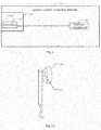
- Fig. 1 is a structural diagram of an earphone capable of detecting heart rate in the embodiment of the present invention.
- the earphone 100 capable of detecting heart rate comprises: a heart rate detection unit 140, a cavity 110 provided in the earphone, and a microphone 120 installed in the cavity 110; Wherein the position where an opening of the cavity 110 clings to a shell of the earphone is the position where the shell of the earphone clings to an auricle of a wearer when the earphone is worn; the shell of the earphone is provided with a hole at the position where the opening of the cavity 110 clings to, and when the earphone is worn, the cavity and the auricle which the hole clings to form an enclosed space; the microphone 120 is configured to collect signals generated by pressure change in the cavity 110 when the earphone is worn; the heart rate detection unit 140 is configured to detect heart rate according to the signals collected by the microphone 120.
- the small cavity 110 is provided in the earphone 100 to place the microphone 120 and forms an enclosed space with the auricle, which reduces interference of external noises, and reinforces signal information collected by the microphone 120.
- the heart rate detection unit 140 is configured to detect the cycle of the signals which are collected by the microphone and have been filtered, and obtain heart rate from the reciprocal of the detected cycle of the signals.
- an microphone In prior arts of detecting heart rate by an earphone, an microphone is generally directly placed in the earphone at a position just directed at the auditory meatus, for collecting pressure change information in the ear cavity generated by vibration of the eardrum. But on one hand, since the space formed by the earphone and the auditory meatus is large, a leak of the air in the auditory meatus will be caused, thus the pressure change information collected by the microphone is very weak; on the other hand, generally the earphone cannot occupy the entire auditory meatus, thus there will be interference from external noises if the microphone is directly placed in the earphone. Therefore, for the earphone shown in Fig. 1 of the invention, another way to install the microphone is designed; see Fig. 2A-2C for specifics.
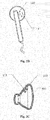
- Fig. 2A is a lateral schematic diagram of an earphone 100 provided with a cavity 110 in the embodiment of the present invention.
- Fig. 2B is a back schematic diagram of an earphone 100 provided with a cavity 110 in the embodiment of the present invention.
- Fig. 2C is a lateral section view of an earphone 100 provided with a cavity 110 in the embodiment of the present invention.
- the present invention designs a small cavity for placing the microphone. See Fig. 2A and Fig. 2B , the scope in the dashed line shown in the figures shows the position of the cavity 110 formed inside the earphone. See Fig. 2C , an opening of the cavity 110 clings to the earphone shell.
- the cavity 110 is at the edge of the earphone at a position close to the auricle, and the earphone is provided with a hole 111 at the position where the cavity clings to.
- the hole 111 is tightly attached to the auricle, thus the cavity 110 and the part of the auricle that presses close to the cavity form an enclosed space.
- the microphone is installed in the cavity 110, and shrink and vibration of the auricle wall will cause change of the pressure in the cavity 110, thus the microphone will collect the pressure change information in the cavity 110.
- the information reflects the frequency of heartbeats to some extent, thus heart rate can be detected hereby.
- intensity of pressure is inversely proportional to volume. That is to say, the smaller the volume, the larger the intensity of pressure, and the larger the pressure acting on a certain area.
- volume When a user wears the earphone, an enclosed space is formed in the auditory meatus, and the fluctuation of pulse pressure of the vessel will cause shrink of the ear wall, thus certain pressure change will be generated in the cavity.
- the pressure change signal will be detected by the microphone.
- the fluctuation of pulse pressure of the vessel is very weak. The larger the enclosed space, the smaller the pressure change that can be detected by the microphone.
- the embodiment installs the microphone in an enclosed small cavity and the small cavity closely clings to the auditory meatus. Since the fluctuation of pulse pressure of the vessel causes shrink and vibration of the ear wall, the vibration makes the microphone in the small cavity detect change of the pressure. And the design of the small cavity will reduce the influence of external interference signals.
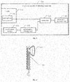
- Fig. 3 is a structural diagram of an earphone capable of detecting heart rate in another embodiment of the present invention.
- the earphone 300 capable of detecting heart rate comprises: a filtering unit 330, a heart rate detection unit 340, a cavity 310 provided in the earphone, and a microphone 320 installed in the cavity 310;
- the position where an opening of the cavity 310 clings to a shell of the earphone is the position where the shell of the earphone clings to an auricle of a wearer when the earphone is worn;
- the earphone shell is provided with a hole at the position where the opening of the cavity 310 clings to, and when the earphone is worn, the cavity and the auricle where the hole clings to form an enclosed space;
- the microphone 320 is configured to collect signals generated by pressure change in the cavity 310 when the earphone is worn, and output the corresponding signals to the filtering unit 130;
- the filtering unit 330 is configured to perform filtering process on the signals collected by the microphone 320 to obtain the filtered signals and output the signals to the heart rate detection unit 340.
- the filtering unit filters the signals collected by the microphone 320 to eliminate the influence of the interference noise on heart rate detection.
- the heart rate detection unit 340 is configure to detect heart rate according to the filtered signals.
- the heart rate detection unit 340 is configured to detect the cycle of the signals related to heart rate, and obtain heart rate from the reciprocal of the detected cycle of the signals.
- the heart rate detection unit 340 can detect the cycle of the signals related to heart rate by using autocorrelation method and threshold value method, etc.
- the filtering unit 330 shown in Fig. 3 comprises: a low pass filter configured to perform low pass filtering process on signals collected by the microphone 320 to filter out high-frequency interference signals.
- a low pass filter configured to perform low pass filtering process on signals collected by the microphone 320 to filter out high-frequency interference signals.
- the frequency of pulse vibration is relatively low (0.3 Hz - 3Hz or so) while the frequency of external noise is higher.
- the influence of external high-frequency noise can be eliminated via the low pass filter.
- the low pass filter can be an FIR filter of which cut-off frequency is 5Hz.
- the low pass filter is adopted to perform low pass filtering process on signals collected by the microphone.
- the microphone in a small cavity is used first for collecting pressure signals in the cavity; then the low pass filter is used for performing low pass filtering on the signals collected by the microphone; at last, after the heart rate signal is obtained, heart rate can be detected.
- Heartbeat has certain periodicity, thus heart rate signal is a signal with certain periodicity.
- the cycle corresponding to the signal can be obtained according to autocorrelation method, and the reciprocal of the cycle is heart rate.
- the external noise signal collected by the microphone will be filtered out after low pass filtering.
- the cycle can be detected by using autocorrelation method, threshold value method, etc, and the reciprocal of the cycle is heart rate.
- heart rate of human under various conditions can be obtained, so that information of physical condition of human body can be obtained, or on this basis human can control their amount of exercise within an appropriate scope in accordance with specific conditions.
- a heart rate detection method used in an earphone of the present invention is provided.
- Fig. 4 is a flowchart showing a heart rate detection method used in an earphone in the embodiment of the present invention. As shown in Fig. 4 , the method comprises:
- the method shown in Fig. 4 further comprises: performing filtering process on the signals collected by the microphone to obtain the filtered signals.
- Detecting heart rate according to the signals collected by the microphone in Step S430 comprises: detecting heart rate according to the filtered signals.
- performing filtering process on the signals collected by the microphone of the method shown in Fig. 4 comprises: performing low pass filtering process on the signals collected by the microphone to filter out high-frequency interference signal.
- detecting heart rate according to the filtered signals comprises: detecting the cycle of the filtered signals, and obtaining heart rate from the reciprocal of the detected cycle of the signals.
- the beneficial effect of the technical scheme of aforesaid embodiment of the present invention comprises that: (1) the enclosed cavity with a relatively small volume is used for placing the microphone, which reduces interference of external noises, and reinforces signal information detected by the microphone. (2) According to feature of the frequency of pulse vibration, a low pass filter is designed to further reduce the influence of external high-frequency noise.
- the invention provides the following solution.
- Fig. 5 is a structural diagram of an earphone capable of detecting heart rate in the embodiment of the present invention.
- the earphone 500 capable of detecting heart rate comprises: a subtractor 550, a heart rate detection unit 560, an acceleration sensor 530, a self-adaptive filtering unit 540, a cavity 510 provided in the earphone, and a microphone 520 installed in the cavity 510; wherein the position where an opening of the cavity 510 clings to a shell of the earphone is the position where the earphone shell clings to the auricle of human ears when the earphone is worn; the earphone shell is provided with a hole at a position where the opening of the cavity 510 clings to, and when the earphone is worn, the cavity and the auricle which the hole clings to form an enclosed space.
- the microphone 520 is configured to collect signals generated by pressure change in the cavity 510 and output the signals to the subtractor 550 when the earphone 500 is worn.
- the acceleration sensor 530 is configured to collect signals generated by body movement of a wearer and output the signals to the self-adaptive filtering unit 540 when the earphone is worn.
- the self-adaptive filtering unit 540 is configured to perform self-adaptive filtering process on the signals collected by the acceleration sensor 530 according to signals related to heart rate, and after obtaining estimated signals of the signals generated by body movement of the wearer in the signals collected by the microphone 520, output the estimated signals to the subtractor 550.
- the subtractor 550 is configured to subtract the estimated signals outputted by the self-adaptive filtering unit 540 from the signals collected by the microphone to obtain signals related to heart rate and output the signals to the heart rate detection unit 560 and the self-adaptive filtering unit 540.
- the heart rate detection unit 560 is configured to detect heart rate according to the signals related to heart rate.
- Self-adaptive filtering process is performed on the signals detected by the acceleration sensor 530 in Fig. 5 , so that human motion signal collected by the microphone 520 can be accurately estimated from human motion signal collected by the acceleration sensor 530, and the purpose is to eliminate the influence of human body movement on heart rate detection.
- the microphone 520 and the acceleration sensor 530 both will detect the vibration signal generated by human body movement. Cycles of the two kinds of signals are the same, but amplitudes are different, thus a self-adaptive filter is needed to be used for eliminating this difference, so that the acceleration signal generated by body movement can be eliminated from the signals collected by the microphone to obtain effective heart rate information.
- the cavity 510 is arranged in the earphone 500 for placing the microphone 520, which reduces interference of external noises, and reinforces signal information collected by the microphone 520.
- the earphone 500 capable of detecting heart rate comprises the acceleration sensor 530 to collect signals generated by body movement of the wearer, and performs self-adaptive filtering on the signals collected by the acceleration sensor 530, and subtracts the acceleration sensor signals after self-adaptive filtering from the signals collected by the microphone, and then detects heart rate. Thereby the influence of body movement of the wearer on the heart rate detection is eliminated.
- the earphone shown in Fig. 5 further comprises a low pass filter, for performing low pass filtering process on the signals collected by the microphone, obtaining the low pass filtered signals and outputting the signals to the subtractor 550.
- the subtractor 550 is configured to subtract the estimated signals outputted by the self-adaptive filtering unit 540 from the low pass filtered signals to obtain signals related to heart rate and output the signals to the heart rate detection unit.
- the frequency of pulse vibration is relatively low (0.3 Hz - 3Hz or so) while the frequency of external noise is higher.
- the influence of external high-frequency noise can be eliminated via the low pass filter.
- the low pass filter can be an FIR filter of which the cut-off frequency is 5Hz.
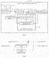
- Fig. 6 is a diagram showing the installing position of an acceleration sensor in an embodiment of the present invention. Movement of human body will cause vibration of human skin accompanying with it, thus the acceleration sensor in the embodiment is installed in the earphone at a position not contacting the skin, so as to avoid the influence of vibration of the skin on the signals collected by the acceleration sensor and increase the accuracy of the signals collected by the acceleration sensor. See Fig. 6 , the acceleration sensor 530 can be installed at any position of the earphone 500 shown by the dashed box in Fig. 6 .
- the data collected by the microphone comprises not only the pressure change information generated by the fluctuation of pulse pressure of the vessel, but also the pressure change information generated in auditory meatus by human body movement.
- the present invention adds the acceleration sensor in the earphone, and the acceleration sensor is installed in the earphone at a position not contacting the skin, for example, the position of the earphone shown by the dashed box in Fig. 6 .
- the acceleration sensor is used for collecting acceleration information generated by human body movement.
- the pressure change information generated in auditory meatus by human body movement has same vibration frequency with acceleration information, and on this basis a certain filter can be adopted to eliminate the interference generated by human body movement.
- the signals generated due to human body movement can be eliminated from the signals detected by the microphone, then the signals generated by the shrink of the auditory meatus per se caused by flow of blood can be obtained.
- the signals are relevant to the frequency of heartbeat, and heart rate information can be obtained based on the signals.
- the microphone collects the pressure change information in auditory meatus caused by human body movement
- the acceleration sensor collects acceleration information corresponding to the human body movement.
- the two kinds of signals have same vibration frequencies, i.e. same cycles, their amplitudes are different.
- the signals cannot be directly taken out from the signals collected by the microphone, thus the embodiment filters out the interference generated due to human body movement in the method of self-adaptive filtering.
- the enclosed cavity with a relatively small volume is used for placing the microphone, which reduces interference of external noises, and reinforces signal information detected by the microphone.
- the acceleration sensor is added to the earphone for collecting signals generated by human body movement, and the self-adaptive filter is designed to further eliminated the influence of the human body movement on heart rate detection.
- a low pass filter is designed to further reduce the influence of external noises. It will be further described below with Fig. 7 as an example.
- Fig. 7 is a structural diagram of an earphone capable of detecting heart rate in another embodiment of the present invention.
- the earphone 700 capable of detecting heart rate comprises: a subtractor 750, a heart rate detection unit 760, a low pass filter 770, an acceleration sensor 730, a self-adaptive filtering unit 740, a cavity 710 provided in the earphone and a microphone 720 installed in the cavity 710.
- the self-adaptive filtering unit 740 comprises: a parameter-adjustable filter 741 and a self-adaptive parameter adjustment unit 742.
- the position where an opening of the cavity 710 clings to a shell of the earphone is the position where the shell of the earphone clings to the auricle of a wearer when the earphone is worn; the earphone shell is provided with a hole at a position where the opening of the cavity 710 clings to, and when the earphone is worn, the cavity and the auricle which the hole clings to form an enclosed space.
- the microphone 720 is configured to collect signals generated by pressure change in the cavity 710 and output the signals to the low pass filter 770 when the earphone 700 is worn.
- the low pass filter 770 is configured to perform low pass filtering process on signals collected by the microphone 720 and output the low pass filtered signals to the subtractor 750.
- the acceleration sensor 730 is configured to collect signals generated by body movement of the wearer when the earphone is worn and output the signals to the parameter-adjustable filter 741 and the self-adaptive parameter adjustment unit 742 in the self-adaptive filtering unit 740.
- the self-adaptive parameter adjustment unit 742 is configured to adjust filtering parameters of the parameter-adjustable filter 741 according to the signals collected by the acceleration sensor 730, the signals related to heart rate, and the preset self-adaptive algorithms.
- the parameter-adjustable filter 741 is configured to perform self-adaptive filtering on the signals collected by the acceleration sensor 730 by using the filtering parameters, and output the estimated signals of the signals generated by body movement of the wearer in the signals collected by the microphone 720 to the subtractor 750.
- the subtractor 750 is configured to subtract the estimated signals outputted by the parameter-adjustable filter 741 from the signals outputted by the low pass filter to obtain signals related to heart rate, and output the signals to the heart rate detection unit 760; the subtractor 750 is further configured to output the signals related to heart rate to the self-adaptive parameter adjustment unit 742.
- the self-adaptive parameter adjustment unit 742 calculates the filtering parameters of the parameter-adjustable filter 741 by using self-adaptive algorithms according to the inputted signals collected by the acceleration sensor 730 and the signals related to heart rate fed back by the subtractor 750.
- the heart rate detection unit 760 is configured to detect heart rate according to the signals related to heart rate.
- the heart rate detection unit 760 is configured to detect the cycle of the signals related to heart rate, and obtain heart rate from the reciprocal of the detected cycle of the signals.
- the heart rate detection unit 760 can detect the cycle of the signals related to heart rate by using existing autocorrelation method and threshold value method, etc.
- Fig. 8 is a general structural diagram of a self-adaptive filter.
- the self-adaptive filter mainly consists of a parameter-adjustable filter and a self-adaptive parameter adjustment unit for adjusting coefficient of the filter.
- the self-adaptive filter does not need to know the knowledge of statistical property of the relevant signals in advance when it is designed. It can gradually "know” or estimate the required statistical property in the course of work and automatically adjust its own parameters according to this, so as to achieve the optimum filtering effect.
- the filtering coefficient of the self-adaptive filter is controlled by the error signal, and e(n) adjusts the self-adaptive coefficient by presetting self-adaptive algorithms, so as to make the mean square error of e(n) the smallest eventually. Now the output signal is most approximate to the expected signal.
- the self-adaptive filter is adopted to perform filtering process on the signals collected by the acceleration sensor to accurately estimate the signals generated due to human body movement collected by the microphone.
- y1(n) is the signal collected by the acceleration sensor 730, i.e. corresponding to the input signal in the self-adaptive filtering unit 740
- y2(n) is the output signal of the self-adaptive filtering unit 740.
- xL(n) represents the corresponding desired signal
- d(n) is corresponding to the error signal (mainly comprising heart rate signal).
- the output signal y2(n) of y1(n) after the filter can become approximate to yL(n) by designing an appropriate transfer function.
- the output signal y2(n) can be used for effectively estimating yL(n), and then the interference of human body movement on heart rate detection can be eliminated from the signals collected by the microphone, then further eliminating the influence of interference signals.
- the signals of the microphone after low pass filtering subtracts the signals of the acceleration sensor after self-adaptive filtering, obtaining signal information d(n) related to heart rate, and on this basis heart rate can be detected.
- the beat of heart has certain periodicity, thus d ⁇ (n)is the signal with certain periodicity.
- the cycle corresponding to the signal can be obtained according to autocorrelation method, and the reciprocal of the cycle is heart rate.
- y(n) represents pressure change signal generated due to human body movement
- d(n) represents pressure change signal generated by the flow of blood
- y1(n) represents acceleration signal generated due to human body movement
- n represents sampling time point.
- xL(n) yL(n)+dL(n).
- y1(n) and y(n) are both signals generated by the same movement.
- y1(n) is corresponding to acceleration information
- y(n) is corresponding to pressure information.
- amplitudes corresponding to the two are different, their vibration frequencies are the same.
- a self-adaptive filter impact response is h(n)
- y2(n) y1(n) * h(n)
- y2(n) can be as approximate as possible to pressure change signal yL(n) generated due to human body movement in x(n) after low pass filtering.
- the self-adaptive parameters of the filter is obtained by using self-adaptive algorithms.
- self-adaptive algorithms There are many methods of realizing the self-adaptive algorithms. For example, the method of minimum mean square error can be adopted, that is, obtaining coefficient of the filter when the value of E(d ⁇ 2 ( n )) is minimum.
- the cycle can be detected by using autocorrelation method, threshold value method, etc, and the reciprocal of the cycle is heart rate.
- the heart rate detection method used in an earphone of the present invention is provided.
- the specific content of each step in the embodiment of the method of the invention see the description related to the embodiment of the product of the invention.
- Fig. 9 is a flowchart showing a heart rate detection method used in an earphone in the embodiment of the present invention. As is shown in Fig. 9 , the method comprises:
- the method shown in Fig. 9 further comprises: performing low pass filtering process on the signals collected by the microphone to obtain low pass filtered signals. Then the subtracting the estimated signals from the signals collected by the microphone to obtain the signals related to heart rate in Step S940 specifically comprises: subtracting the estimated signals from the low pass filtered signals to obtain the signals related to heart rate.
- performing self-adaptive filtering process on the signals collected by the acceleration sensor to obtain estimated signals of the signals generated by body movement of the wearer in the signals collected by the microphone in Step S930 comprises:
- detecting heart rate according to the signals related to heart rate in Step S950 comprises: detecting cycle of the signals related to heart rate, and obtaining the heart rate from the reciprocal of the detected cycle of the signals.
- the beneficial effect of the technical scheme in the embodiment shown in Figs. 5-9 of the present invention comprises:
Landscapes
- Health & Medical Sciences (AREA)
- Life Sciences & Earth Sciences (AREA)
- Engineering & Computer Science (AREA)
- Physics & Mathematics (AREA)
- Signal Processing (AREA)
- General Health & Medical Sciences (AREA)
- Veterinary Medicine (AREA)
- Heart & Thoracic Surgery (AREA)
- Medical Informatics (AREA)
- Molecular Biology (AREA)
- Surgery (AREA)
- Animal Behavior & Ethology (AREA)
- Biomedical Technology (AREA)
- Public Health (AREA)
- Pathology (AREA)
- Biophysics (AREA)
- Cardiology (AREA)
- Physiology (AREA)
- Acoustics & Sound (AREA)
- Psychiatry (AREA)
- Computer Vision & Pattern Recognition (AREA)
- Artificial Intelligence (AREA)
- Power Engineering (AREA)
- Computational Linguistics (AREA)
- Quality & Reliability (AREA)
- Audiology, Speech & Language Pathology (AREA)
- Human Computer Interaction (AREA)
- Multimedia (AREA)
- Otolaryngology (AREA)
- Measuring Pulse, Heart Rate, Blood Pressure Or Blood Flow (AREA)
- Headphones And Earphones (AREA)
Abstract
Description
- The invention relates to the field of earphone and heart rate detection technology, particularly to a heart rate detection method used in an earphone and an earphone capable of detecting heart rate.
- With the continuous development of social economy, people's material standard of living improves with each passing day, and people are paying more attention to their health. Heart rate detection will provide very important information on health for people. Any display of abnormal heart rate will indicate a problem of health, thus heart rate detection can find out whether or not our body has a problem without delay. Heart rate detection can also reflect to some extent whether or not human's motion intensity is appropriate. In order to achieve the optimum effect of exercise, people should keep their heart rate within a certain scope in the course of exercise, and the heart rate detection can provide an index for a reasonable amount of exercise.
- In addition, lots of people like wearing an earphone to listen to music during exercise. In order to detect the heart rate during exercise without the need to carry around other devices, people start to study relevant technology of how to detect heart rate by using an earphone.
- For heart rate detection technology, in addition to heart rate belt, a technology of detecting heart rate by using an earphone emerges at present to achieve the purpose of convenience and accuracy.
- The technology of detecting heart rate by using an earphone just emerged in recent years. On October 23 to 25, 2013, Kaiteki Corporation and Bifrostec Corporation exhibited a technology of detecting pulse fluctuation by using an earphone at a health-equipment exhibition in Yokohama, Japan. The technology uses the earphone clinging to the auditory meatus to form an enclosed space, and a certain pressure will be generated in the auditory meatus because of vibration of the eardrum, and the pressure will change with the change of vibration. Information of the pressure change in the auditory meatus will be collected by a microphone, thus the purpose of detecting heart rate can be achieved. However, the earphone cannot occupy the entire auditory meatus, which will cause a leak of the air in the auditory meatus, and, as a result, the microphone cannot detect the change of the pressure and the heart rate detection will be interfered by external noises.
- In view of aforesaid problem, the present invention provides a heart rate detection method used in an earphone and an earphone capable of detecting heart rate to overcome aforesaid problem or at least partly solve aforesaid problem.
- The present invention provides a heart rate detection method used in an earphone, wherein the method comprises:
- providing a cavity inside the earphone, and installing a microphone in the cavity; the position where an opening of said cavity clings to a shell of the earphone is the position where the shell of the earphone clings to an auricle of a wearer when the earphone is worn; the shell of the earphone is provided with a hole at the position where the opening of said cavity clings to, and when the earphone is worn, the cavity and the auricle which the hole clings to form an enclosed space;
- collecting signals generated by pressure change in said cavity by said microphone when the earphone is worn;
- taking the signals collected by the microphone as signals related to heart rate; and
- detecting heart rate according to the signals related to heart rate.
- Optionally, the method comprises: providing an acceleration sensor in the earphone;
collecting signals generated by body movement of the wearer by the acceleration sensor when the earphone is worn;
performing self-adaptive filtering process on the signals collected by the acceleration sensor to obtaining estimated signals of the signals generated by body movement of the wearer in the signals collected by the microphone;
subtracting the estimated signals from the signals collected by the microphone to obtain signals related to heart rate. - The present invention also provides an earphone capable of detecting heart rate, wherein the earphone comprises: a heart rate detection unit, a cavity provided in the earphone, and a microphone installed in the cavity;
wherein the position where an opening of the cavity clings to a shell of the earphone is the position where the shell of the earphone clings to an auricle of a wearer when the earphone is worn; the shell of the earphone is provided with a hole at the position where the opening of the cavity clings to, and when the earphone is worn, the cavity and the auricle which the hole clings to form an enclosed space;
the microphone is configured to collect signals generated by pressure change in the cavity when the earphone is worn, the signals collected by the microphone are being taken as signals related to heart rate; and
the heart rate detection unit is configured to detect heart rate according to the signals related to heart rate. - Optionally, the earphone further comprises: an acceleration sensor, a self-adaptive filtering unit, and a subtractor;
the acceleration sensor is configured to collect signals generated by body movement of the wearer and output the signals to the self-adaptive filtering unit when the earphone is worn;
the self-adaptive filtering unit is configured to perform self-adaptive filtering process on the signals collected by the acceleration sensor according to the signals related to heart rate to obtaining estimated signals of the signals generated by body movement of the wearer in the signals collected by the microphone, output the estimated signals to the subtractor; and
the subtractor is configured to subtract the estimated signals from the signals collected by the microphone to obtain the signals related to heart rate, and output the signals related to heart rate to the heart rate detection unit and the self-adaptive filtering unit. - As can be seen from the foregoing, the technical scheme in the embodiment of the invention uses the enclosed cavity formed by the cavity in the earphone and the earphone shell to place the microphone, which reduces interference of external noises, and reinforces signal information collected by the microphone. The acceleration sensor is further added to the earphone for collecting signals generated due to human body movement, and the influence of the human body movement on heart rate detection is eliminated by designing the self-adaptive filter.
- Above description is only a summary of the technical scheme of the present invention. In order to know the technical means of the present invention more clearly so that it can be put into effect according to the content of the description, and to make the aforesaid and other purpose, features and advantages of the invention clearer, the embodiments of the invention will be described in further detail with reference to the drawings.
-
-
Fig. 1 is a structural diagram of an earphone capable of detecting heart rate in an embodiment of the present invention; -
Fig. 2A is a lateral schematic diagram of theearphone 100 provided with acavity 110 in the embodiment of the present invention; -
Fig. 2B is a back schematic diagram of theearphone 100 provided with thecavity 110 in the embodiment of the present invention; -
Fig. 2C is a lateral section view of theearphone 100 provided with thecavity 110 in the embodiment of the present invention; -
Fig. 3 is a structural diagram of an earphone capable of detecting heart rate in another embodiment of the present invention; -
Fig. 4 is a flowchart showing a heart rate detection method used in an earphone in an embodiment of the present invention; -
Fig. 5 is a structural diagram of an earphone capable of detecting heart rate in an embodiment of the present invention; -
Fig. 6 is a diagram showing the installing position of an acceleration sensor in an embodiment of the present invention; -
Fig. 7 is a structural diagram of an earphone capable of detecting heart rate in another embodiment of the present invention; -
Fig. 8 is a general structural diagram of a self-adaptive filter; and -
Fig. 9 is a flowchart showing a heart rate detection method used in an earphone in the embodiment of the present invention. - The embodiments of the present disclosure are described in further detail with reference to the drawings below. Although the drawings show the embodiments of the present disclosure, it should be understood that the disclosure can be implemented in various forms and is not intended to be limited by the embodiments described here. On the contrary, the embodiments are provided to make the invention understood more thoroughly and completely convey the scope of the disclosure to a person skilled in the art.
-
Fig. 1 is a structural diagram of an earphone capable of detecting heart rate in the embodiment of the present invention. As shown inFig. 1 , theearphone 100 capable of detecting heart rate comprises: a heartrate detection unit 140, acavity 110 provided in the earphone, and amicrophone 120 installed in thecavity 110;
Wherein the position where an opening of thecavity 110 clings to a shell of the earphone is the position where the shell of the earphone clings to an auricle of a wearer when the earphone is worn; the shell of the earphone is provided with a hole at the position where the opening of thecavity 110 clings to, and when the earphone is worn, the cavity and the auricle which the hole clings to form an enclosed space;
themicrophone 120 is configured to collect signals generated by pressure change in thecavity 110 when the earphone is worn;
the heartrate detection unit 140 is configured to detect heart rate according to the signals collected by themicrophone 120. - In the
earphone 100 capable of detecting heart rate shown inFig. 1 , thesmall cavity 110 is provided in theearphone 100 to place themicrophone 120 and forms an enclosed space with the auricle, which reduces interference of external noises, and reinforces signal information collected by themicrophone 120. - In an embodiment of the invention, the heart
rate detection unit 140 is configured to detect the cycle of the signals which are collected by the microphone and have been filtered, and obtain heart rate from the reciprocal of the detected cycle of the signals. - In prior arts of detecting heart rate by an earphone, an microphone is generally directly placed in the earphone at a position just directed at the auditory meatus, for collecting pressure change information in the ear cavity generated by vibration of the eardrum. But on one hand, since the space formed by the earphone and the auditory meatus is large, a leak of the air in the auditory meatus will be caused, thus the pressure change information collected by the microphone is very weak; on the other hand, generally the earphone cannot occupy the entire auditory meatus, thus there will be interference from external noises if the microphone is directly placed in the earphone. Therefore, for the earphone shown in
Fig. 1 of the invention, another way to install the microphone is designed; seeFig. 2A-2C for specifics. -
Fig. 2A is a lateral schematic diagram of anearphone 100 provided with acavity 110 in the embodiment of the present invention.Fig. 2B is a back schematic diagram of anearphone 100 provided with acavity 110 in the embodiment of the present invention.Fig. 2C is a lateral section view of anearphone 100 provided with acavity 110 in the embodiment of the present invention. In order to better collect useful signals related to heartbeat, the present invention designs a small cavity for placing the microphone. SeeFig. 2A andFig. 2B , the scope in the dashed line shown in the figures shows the position of thecavity 110 formed inside the earphone. SeeFig. 2C , an opening of thecavity 110 clings to the earphone shell. As can be seen, in the embodiment, thecavity 110 is at the edge of the earphone at a position close to the auricle, and the earphone is provided with ahole 111 at the position where the cavity clings to. When the earphone is worn, thehole 111 is tightly attached to the auricle, thus thecavity 110 and the part of the auricle that presses close to the cavity form an enclosed space. The microphone is installed in thecavity 110, and shrink and vibration of the auricle wall will cause change of the pressure in thecavity 110, thus the microphone will collect the pressure change information in thecavity 110. The information reflects the frequency of heartbeats to some extent, thus heart rate can be detected hereby. - In physics, for an enclosed space (without regard to temperature), intensity of pressure is inversely proportional to volume. That is to say, the smaller the volume, the larger the intensity of pressure, and the larger the pressure acting on a certain area. When a user wears the earphone, an enclosed space is formed in the auditory meatus, and the fluctuation of pulse pressure of the vessel will cause shrink of the ear wall, thus certain pressure change will be generated in the cavity. The pressure change signal will be detected by the microphone. Generally speaking, the fluctuation of pulse pressure of the vessel is very weak. The larger the enclosed space, the smaller the pressure change that can be detected by the microphone. In order to enhance the intensity of the pressure change detected by the microphone, the embodiment installs the microphone in an enclosed small cavity and the small cavity closely clings to the auditory meatus. Since the fluctuation of pulse pressure of the vessel causes shrink and vibration of the ear wall, the vibration makes the microphone in the small cavity detect change of the pressure. And the design of the small cavity will reduce the influence of external interference signals.
-
Fig. 3 is a structural diagram of an earphone capable of detecting heart rate in another embodiment of the present invention. As shown inFig. 3 , theearphone 300 capable of detecting heart rate comprises: afiltering unit 330, a heartrate detection unit 340, acavity 310 provided in the earphone, and amicrophone 320 installed in thecavity 310; - Wherein the position where an opening of the
cavity 310 clings to a shell of the earphone is the position where the shell of the earphone clings to an auricle of a wearer when the earphone is worn; the earphone shell is provided with a hole at the position where the opening of thecavity 310 clings to, and when the earphone is worn, the cavity and the auricle where the hole clings to form an enclosed space;
themicrophone 320 is configured to collect signals generated by pressure change in thecavity 310 when the earphone is worn, and output the corresponding signals to the filtering unit 130;
thefiltering unit 330 is configured to perform filtering process on the signals collected by themicrophone 320 to obtain the filtered signals and output the signals to the heartrate detection unit 340. Here the filtering unit filters the signals collected by themicrophone 320 to eliminate the influence of the interference noise on heart rate detection. - The heart
rate detection unit 340 is configure to detect heart rate according to the filtered signals. - In an embodiment of the invention, the heart
rate detection unit 340 is configured to detect the cycle of the signals related to heart rate, and obtain heart rate from the reciprocal of the detected cycle of the signals. For example, the heartrate detection unit 340 can detect the cycle of the signals related to heart rate by using autocorrelation method and threshold value method, etc. - In an embodiment of the invention, the
filtering unit 330 shown inFig. 3 comprises: a low pass filter configured to perform low pass filtering process on signals collected by themicrophone 320 to filter out high-frequency interference signals. This is because that the frequency of pulse vibration is relatively low (0.3 Hz - 3Hz or so) while the frequency of external noise is higher. According to this feature, the influence of external high-frequency noise can be eliminated via the low pass filter. For example, the low pass filter can be an FIR filter of which cut-off frequency is 5Hz. - In the earphone shown in
Fig. 3 , the low pass filter is adopted to perform low pass filtering process on signals collected by the microphone. As shown inFig. 3 , the microphone in a small cavity is used first for collecting pressure signals in the cavity; then the low pass filter is used for performing low pass filtering on the signals collected by the microphone; at last, after the heart rate signal is obtained, heart rate can be detected. Heartbeat has certain periodicity, thus heart rate signal is a signal with certain periodicity. The cycle corresponding to the signal can be obtained according to autocorrelation method, and the reciprocal of the cycle is heart rate. - The specific process is as follows:
- Suppose the signal detected by the microphone is: x(n) = y(n)+d(n);
- wherein y(n) represents interference signal; d(n) represents the pressure change signal generated by flow of blood; and n represents sampling time point;
- After low pass filtering, the signal of x(n) becomes: xL(n) = dL(n). The external noise signal collected by the microphone will be filtered out after low pass filtering.
- After dL(n) is obtained, according to periodicity characteristic of the signal, the cycle can be detected by using autocorrelation method, threshold value method, etc, and the reciprocal of the cycle is heart rate.
- Via the earphone in the embodiment shown in
Fig. 1 orFig. 3 , heart rate of human under various conditions (still, moving, etc) can be obtained, so that information of physical condition of human body can be obtained, or on this basis human can control their amount of exercise within an appropriate scope in accordance with specific conditions. - On the basis of aforesaid embodiment, a heart rate detection method used in an earphone of the present invention is provided.
-
Fig. 4 is a flowchart showing a heart rate detection method used in an earphone in the embodiment of the present invention. As shown inFig. 4 , the method comprises: - Step S410, providing a cavity inside the earphone, and installing a microphone in the cavity; the position where an opening of the cavity clings to a shell of the earphone is the position where the shell of the earphone clings to an auricle of a wearer when the earphone is worn; the shell of the earphone is provided with a hole at the position where the opening of the cavity clings to, and when the earphone is worn, the cavity and the auricle which the hole clings to form an enclosed space;
- Step S420, collecting signals generated by pressure change in the cavity by the microphone when the earphone is worn;
- Step S430, detecting heart rate according to the signals collected by the microphone, that is, taking the signals collected by the microphone as signals related to heart rate, and detecting the heart rate according to the signals related to heart rate.
- In an embodiment of the invention, before Step S430, the method shown in
Fig. 4 further comprises: performing filtering process on the signals collected by the microphone to obtain the filtered signals. Detecting heart rate according to the signals collected by the microphone in Step S430 comprises: detecting heart rate according to the filtered signals. - In an embodiment of the invention, performing filtering process on the signals collected by the microphone of the method shown in
Fig. 4 comprises: performing low pass filtering process on the signals collected by the microphone to filter out high-frequency interference signal. - In an embodiment of the invention, detecting heart rate according to the filtered signals comprises: detecting the cycle of the filtered signals, and obtaining heart rate from the reciprocal of the detected cycle of the signals.
- In summary, the beneficial effect of the technical scheme of aforesaid embodiment of the present invention comprises that: (1) the enclosed cavity with a relatively small volume is used for placing the microphone, which reduces interference of external noises, and reinforces signal information detected by the microphone. (2) According to feature of the frequency of pulse vibration, a low pass filter is designed to further reduce the influence of external high-frequency noise.
- For using an earphone to detect heart rate, there is another important factor affecting accurate detection of heart rate, that is, human body movement. Human body movements will inevitably cause vibration of ear wall, and this vibration similarly will cause pressure change in auditory meatus. This pressure change will be collected by the microphone, thus interferes the analysis on heart rate signals. Thus, the invention provides the following solution.
-
Fig. 5 is a structural diagram of an earphone capable of detecting heart rate in the embodiment of the present invention. As shown inFig. 5 , theearphone 500 capable of detecting heart rate comprises: asubtractor 550, a heartrate detection unit 560, anacceleration sensor 530, a self-adaptive filtering unit 540, acavity 510 provided in the earphone, and amicrophone 520 installed in thecavity 510;
wherein the position where an opening of thecavity 510 clings to a shell of the earphone is the position where the earphone shell clings to the auricle of human ears when the earphone is worn; the earphone shell is provided with a hole at a position where the opening of thecavity 510 clings to, and when the earphone is worn, the cavity and the auricle which the hole clings to form an enclosed space. - The
microphone 520 is configured to collect signals generated by pressure change in thecavity 510 and output the signals to thesubtractor 550 when theearphone 500 is worn. - The
acceleration sensor 530 is configured to collect signals generated by body movement of a wearer and output the signals to the self-adaptive filtering unit 540 when the earphone is worn. - The self-
adaptive filtering unit 540 is configured to perform self-adaptive filtering process on the signals collected by theacceleration sensor 530 according to signals related to heart rate, and after obtaining estimated signals of the signals generated by body movement of the wearer in the signals collected by themicrophone 520, output the estimated signals to thesubtractor 550. - The
subtractor 550 is configured to subtract the estimated signals outputted by the self-adaptive filtering unit 540 from the signals collected by the microphone to obtain signals related to heart rate and output the signals to the heartrate detection unit 560 and the self-adaptive filtering unit 540. - The heart
rate detection unit 560 is configured to detect heart rate according to the signals related to heart rate. - Self-adaptive filtering process is performed on the signals detected by the
acceleration sensor 530 inFig. 5 , so that human motion signal collected by themicrophone 520 can be accurately estimated from human motion signal collected by theacceleration sensor 530, and the purpose is to eliminate the influence of human body movement on heart rate detection. Themicrophone 520 and theacceleration sensor 530 both will detect the vibration signal generated by human body movement. Cycles of the two kinds of signals are the same, but amplitudes are different, thus a self-adaptive filter is needed to be used for eliminating this difference, so that the acceleration signal generated by body movement can be eliminated from the signals collected by the microphone to obtain effective heart rate information. - In the
earphone 500 capable of detecting heart rate shown inFig. 5 , thecavity 510 is arranged in theearphone 500 for placing themicrophone 520, which reduces interference of external noises, and reinforces signal information collected by themicrophone 520. In addition, theearphone 500 capable of detecting heart rate comprises theacceleration sensor 530 to collect signals generated by body movement of the wearer, and performs self-adaptive filtering on the signals collected by theacceleration sensor 530, and subtracts the acceleration sensor signals after self-adaptive filtering from the signals collected by the microphone, and then detects heart rate. Thereby the influence of body movement of the wearer on the heart rate detection is eliminated. - In an embodiment of the invention, the earphone shown in
Fig. 5 further comprises a low pass filter, for performing low pass filtering process on the signals collected by the microphone, obtaining the low pass filtered signals and outputting the signals to thesubtractor 550. That is, thesubtractor 550 is configured to subtract the estimated signals outputted by the self-adaptive filtering unit 540 from the low pass filtered signals to obtain signals related to heart rate and output the signals to the heart rate detection unit. This is because that the frequency of pulse vibration is relatively low (0.3 Hz - 3Hz or so) while the frequency of external noise is higher. According to this feature, the influence of external high-frequency noise can be eliminated via the low pass filter. For example, the low pass filter can be an FIR filter of which the cut-off frequency is 5Hz. - The specific way of providing the
cavity 510 in theearphone 500 and installing themicrophone 520 in thecavity 510 in the present embodiment are same with the scheme shown inFigs. 2A-2C , thus it will not be repeated here. -
Fig. 6 is a diagram showing the installing position of an acceleration sensor in an embodiment of the present invention. Movement of human body will cause vibration of human skin accompanying with it, thus the acceleration sensor in the embodiment is installed in the earphone at a position not contacting the skin, so as to avoid the influence of vibration of the skin on the signals collected by the acceleration sensor and increase the accuracy of the signals collected by the acceleration sensor. SeeFig. 6 , theacceleration sensor 530 can be installed at any position of theearphone 500 shown by the dashed box inFig. 6 . - In practice, even if the earphone can occupy the entire auditory meatus to form a completely enclosed cavity, the influence of human body movement on heart rate detection is inevitable, because human body movement will inevitably cause vibration of the ear wall, and pressure change in the cavity generated by the vibration will similarly be detected by the microphone. Thus the data collected by the microphone comprises not only the pressure change information generated by the fluctuation of pulse pressure of the vessel, but also the pressure change information generated in auditory meatus by human body movement. In order to eliminate the influence of the human body movement on heart rate detection, the present invention adds the acceleration sensor in the earphone, and the acceleration sensor is installed in the earphone at a position not contacting the skin, for example, the position of the earphone shown by the dashed box in
Fig. 6 . The acceleration sensor is used for collecting acceleration information generated by human body movement. The pressure change information generated in auditory meatus by human body movement has same vibration frequency with acceleration information, and on this basis a certain filter can be adopted to eliminate the interference generated by human body movement. - According to the foregoing analysis, if the signals generated due to human body movement can be eliminated from the signals detected by the microphone, then the signals generated by the shrink of the auditory meatus per se caused by flow of blood can be obtained. The signals are relevant to the frequency of heartbeat, and heart rate information can be obtained based on the signals.
- The microphone collects the pressure change information in auditory meatus caused by human body movement, and the acceleration sensor collects acceleration information corresponding to the human body movement. Though the two kinds of signals have same vibration frequencies, i.e. same cycles, their amplitudes are different. The signals cannot be directly taken out from the signals collected by the microphone, thus the embodiment filters out the interference generated due to human body movement in the method of self-adaptive filtering.
- In summary, in the embodiment of the invention: first, the enclosed cavity with a relatively small volume is used for placing the microphone, which reduces interference of external noises, and reinforces signal information detected by the microphone. Second, the acceleration sensor is added to the earphone for collecting signals generated by human body movement, and the self-adaptive filter is designed to further eliminated the influence of the human body movement on heart rate detection. Furthermore, according to the feature of the frequency of pulse vibration, a low pass filter is designed to further reduce the influence of external noises. It will be further described below with
Fig. 7 as an example. -
Fig. 7 is a structural diagram of an earphone capable of detecting heart rate in another embodiment of the present invention. As shown inFig. 7 , theearphone 700 capable of detecting heart rate comprises: asubtractor 750, a heartrate detection unit 760, a low pass filter 770, anacceleration sensor 730, a self-adaptive filtering unit 740, acavity 710 provided in the earphone and amicrophone 720 installed in thecavity 710. Wherein, the self-adaptive filtering unit 740 comprises: a parameter-adjustable filter 741 and a self-adaptiveparameter adjustment unit 742. - Wherein the position where an opening of the
cavity 710 clings to a shell of the earphone is the position where the shell of the earphone clings to the auricle of a wearer when the earphone is worn; the earphone shell is provided with a hole at a position where the opening of thecavity 710 clings to, and when the earphone is worn, the cavity and the auricle which the hole clings to form an enclosed space. - The
microphone 720 is configured to collect signals generated by pressure change in thecavity 710 and output the signals to the low pass filter 770 when theearphone 700 is worn. - The low pass filter 770 is configured to perform low pass filtering process on signals collected by the
microphone 720 and output the low pass filtered signals to thesubtractor 750. - The
acceleration sensor 730 is configured to collect signals generated by body movement of the wearer when the earphone is worn and output the signals to the parameter-adjustable filter 741 and the self-adaptiveparameter adjustment unit 742 in the self-adaptive filtering unit 740. - The self-adaptive
parameter adjustment unit 742 is configured to adjust filtering parameters of the parameter-adjustable filter 741 according to the signals collected by theacceleration sensor 730, the signals related to heart rate, and the preset self-adaptive algorithms. - The parameter-
adjustable filter 741 is configured to perform self-adaptive filtering on the signals collected by theacceleration sensor 730 by using the filtering parameters, and output the estimated signals of the signals generated by body movement of the wearer in the signals collected by themicrophone 720 to thesubtractor 750. - The
subtractor 750 is configured to subtract the estimated signals outputted by the parameter-adjustable filter 741 from the signals outputted by the low pass filter to obtain signals related to heart rate, and output the signals to the heartrate detection unit 760; thesubtractor 750 is further configured to output the signals related to heart rate to the self-adaptiveparameter adjustment unit 742. - Here the self-adaptive
parameter adjustment unit 742 calculates the filtering parameters of the parameter-adjustable filter 741 by using self-adaptive algorithms according to the inputted signals collected by theacceleration sensor 730 and the signals related to heart rate fed back by thesubtractor 750. - The heart
rate detection unit 760 is configured to detect heart rate according to the signals related to heart rate. - In an embodiment of the invention, the heart
rate detection unit 760 is configured to detect the cycle of the signals related to heart rate, and obtain heart rate from the reciprocal of the detected cycle of the signals. For example, the heartrate detection unit 760 can detect the cycle of the signals related to heart rate by using existing autocorrelation method and threshold value method, etc. -
Fig. 8 is a general structural diagram of a self-adaptive filter. As shown inFig. 8 , the self-adaptive filter mainly consists of a parameter-adjustable filter and a self-adaptive parameter adjustment unit for adjusting coefficient of the filter. The self-adaptive filter does not need to know the knowledge of statistical property of the relevant signals in advance when it is designed. It can gradually "know" or estimate the required statistical property in the course of work and automatically adjust its own parameters according to this, so as to achieve the optimum filtering effect. InFig. 8 , Ex(n) is expected signal; In(n) is input signal; Out(n) is output signal; e(n) is evaluated error; and e(n) = Ex(n)-Out(n). The filtering coefficient of the self-adaptive filter is controlled by the error signal, and e(n) adjusts the self-adaptive coefficient by presetting self-adaptive algorithms, so as to make the mean square error of e(n) the smallest eventually. Now the output signal is most approximate to the expected signal. - In the earphone shown in
Fig. 7 , the self-adaptive filter is adopted to perform filtering process on the signals collected by the acceleration sensor to accurately estimate the signals generated due to human body movement collected by the microphone. As shown inFig. 7 , y1(n) is the signal collected by theacceleration sensor 730, i.e. corresponding to the input signal in the self-adaptive filtering unit 740, and y2(n) is the output signal of the self-adaptive filtering unit 740. xL(n) represents the corresponding desired signal, and d(n) is corresponding to the error signal (mainly comprising heart rate signal). There is certain correlation between yL(n) and y1(n), thus the output signal y2(n) of y1(n) after the filter can become approximate to yL(n) by designing an appropriate transfer function. For example, according to the minimum mean square error principle, when the expected value of mean square of the error signal is minimum, the output signal y2(n) can be used for effectively estimating yL(n), and then the interference of human body movement on heart rate detection can be eliminated from the signals collected by the microphone, then further eliminating the influence of interference signals. The signals of the microphone after low pass filtering subtracts the signals of the acceleration sensor after self-adaptive filtering, obtaining signal information d(n) related to heart rate, and on this basis heart rate can be detected. The beat of heart has certain periodicity, thus d̂(n)is the signal with certain periodicity. The cycle corresponding to the signal can be obtained according to autocorrelation method, and the reciprocal of the cycle is heart rate. - The specific process is as follows:
- suppose the signals detected by the microphone is: x(n) = y(n)+d(n); and the signals detected by the acceleration sensor is y1(n).
- Wherein y(n) represents pressure change signal generated due to human body movement; d(n) represents pressure change signal generated by the flow of blood; y1(n) represents acceleration signal generated due to human body movement and n represents sampling time point.
- After low pass filtering, the signal of x(n) becomes: xL(n) = yL(n)+dL(n).
- y1(n) and y(n) are both signals generated by the same movement. y1(n) is corresponding to acceleration information, and y(n) is corresponding to pressure information. Although amplitudes corresponding to the two are different, their vibration frequencies are the same. In order to eliminate y(n) from x(n), a self-adaptive filter (impact response is h(n)) is selected to filter y1(n), obtaining y2(n) = y1(n) * h(n), so that y2(n) can be as approximate as possible to pressure change signal yL(n) generated due to human body movement in x(n) after low pass filtering.
- Thus the signals generated because of shrink of the auditory meatus can be expressed as:

- The self-adaptive parameters of the filter is obtained by using self-adaptive algorithms. There are many methods of realizing the self-adaptive algorithms. For example, the method of minimum mean square error can be adopted, that is, obtaining coefficient of the filter when the value of E(d̂2(n)) is minimum.
- After d̂(n) is obtained, according to the periodicity characteristic of the signal, the cycle can be detected by using autocorrelation method, threshold value method, etc, and the reciprocal of the cycle is heart rate.
- Via the earphone in the embodiment shown in
Fig. 5 orFig. 7 , people's heart rate under various conditions (still, moving, etc) can be obtained, so that the information of physical condition of human body can be obtained, or on this basis people can control their amount of exercise within an appropriate scope in accordance with specific conditions. - On the basis of aforesaid embodiment, the heart rate detection method used in an earphone of the present invention is provided. For the specific content of each step in the embodiment of the method of the invention, see the description related to the embodiment of the product of the invention.
-
Fig. 9 is a flowchart showing a heart rate detection method used in an earphone in the embodiment of the present invention. As is shown inFig. 9 , the method comprises: - Step S910, providing a cavity in the earphone and installing a microphone in the cavity; the position where an opening of the cavity clings to a shell of the earphone is the position where the shell of the earphone clings to an auricle of a wearer when the earphone is worn; the shell of the earphone is provided with a hole at a position where the opening of the cavity clings to, and when the earphone is worn, the cavity and the auricle which the hole clings to form an enclosed space; providing an acceleration sensor in the earphone. For example, the acceleration sensor can be provided in the earphone at a position not contacting the skin of a wearer;
- Step S920, when the earphone is worn, collecting signals generated by pressure change in the cavity by the microphone, and collecting signals generated by body movement of the wearer by the acceleration sensor;
- Step S930, performing self-adaptive filtering process on the signals collected by the acceleration sensor to obtain estimated signals of the signals generated by body movement of the wearer in the signals collected by the microphone;
- Step S940, subtracting the estimated signals from the signals collected by the microphone to obtain signals related to heart rate;
- Step S950, detecting heart rate according to the signals related to heart rate.
- In an embodiment of the invention, before subtracting the estimated signals from the signals collected by the microphone to obtain the signals related to heart rate, the method shown in
Fig. 9 further comprises: performing low pass filtering process on the signals collected by the microphone to obtain low pass filtered signals. Then the subtracting the estimated signals from the signals collected by the microphone to obtain the signals related to heart rate in Step S940 specifically comprises: subtracting the estimated signals from the low pass filtered signals to obtain the signals related to heart rate. - In an embodiment of the invention, performing self-adaptive filtering process on the signals collected by the acceleration sensor to obtain estimated signals of the signals generated by body movement of the wearer in the signals collected by the microphone in Step S930 comprises:
- calculating self-adaptive filtering parameters according to the signals collected by the acceleration sensor, the signals related to heart rate and the preset self-adaptive algorithms;
- performing self-adaptive filtering on the signals collected by the acceleration sensor according to the self-adaptive filtering parameters to obtain the estimated signal.
- In an embodiment of the invention, detecting heart rate according to the signals related to heart rate in Step S950 comprises: detecting cycle of the signals related to heart rate, and obtaining the heart rate from the reciprocal of the detected cycle of the signals.
- In summary, the beneficial effect of the technical scheme in the embodiment shown in
Figs. 5-9 of the present invention comprises: - (1) The enclosed cavity with a relatively small volume is used for placing the microphone, which reduces interference of external noises, and reinforces signal information detected by the microphone.
- (2) The acceleration sensor is added to the earphone for collecting signals generated due to human body movement, and the self-adaptive filter is designed to eliminate the influence of human body movement on heart rate detection.
- (3) According to feature of the frequency of pulse vibration, a low pass filter is designed to further reduce the influence of external high-frequency noise.
- The foregoing descriptions merely show preferred embodiments of the present invention, and are not intended to limit the protection scope of the present invention. Any modification, equivalent replacement and improvement made within the spirit and principle of the present invention shall fall into the protection scope of the present invention.
Claims (14)
- A heart rate detection method used in an earphone, wherein said method comprises:providing a cavity inside the earphone, and installing a microphone in said cavity; the position where an opening of said cavity clings to a shell of the earphone is the position where the shell of the earphone clings to an auricle of a wearer when the earphone is worn; the shell of the earphone is provided with a hole at the position where the opening of said cavity clings to, and when the earphone is worn, said cavity and the auricle which said hole clings to form an enclosed space;collecting signals generated by pressure change in said cavity by said microphone when the earphone is worn;taking the signals collected by the microphone as signals related to heart rate; anddetecting heart rate according to the signals related to heart rate.
- The method according to claim 1, wherein the method further comprises: performing filtering process on the signals collected by said microphone to obtain filtered signals;
said detecting heart rate according to the signals related to heart rate comprises: detecting heart rate according to said filtered signals. - The method according to claim 1, wherein said method comprises:providing an acceleration sensor in the earphone;collecting signals generated by body movement of the wearer by said acceleration sensor when the earphone is worn;performing self-adaptive filtering process on the signals collected by said acceleration sensor to obtain estimated signals of the signals generated by body movement of the wearer in the signals collected by the microphone;subtracting said estimated signals from the signals collected by the microphone to obtain signals related to heart rate.
- The method according to claim 3, wherein
before subtracting said estimated signals from the signals collected by the microphone to obtain signals related to heart rate, the method further comprises: performing low pass filtering process on the signals collected by said microphone to obtain low pass filtered signals;
said subtracting said estimated signals from the signals collected by the microphone to obtain signals related to heart rate specifically comprises: subtracting said estimated signals from said low pass filtered signals to obtain signals related to heart rate. - The method according to claim 3, wherein said performing self-adaptive filtering process on the signals collected by said acceleration sensor to obtain estimated signals of the signals generated by body movement of the wearer in the signals collected by the microphone comprises:calculating self-adaptive filtering parameters according to the signals collected by the acceleration sensor, the signals related to heart rate and preset self-adaptive algorithms;performing self-adaptive filtering on the signals collected by the acceleration sensor according to said self-adaptive filtering parameters to obtain said estimated signals.
- The method according to claim 3, wherein said detecting heart rate according to the signals related to heart rate comprises:detecting the cycle of said signals related to heart rate;obtaining heart rate from reciprocal of the detected cycle of the signals.
- The method according to claim 3, wherein said providing an acceleration sensor in the earphone comprises: installing the acceleration sensor in the earphone at a position not contacting the wearer's skin.
- An earphone capable of detecting heart rate, wherein the earphone comprises: a heart rate detection unit, a cavity provided in the earphone, and a microphone installed in said cavity;
wherein the position where an opening of said cavity clings to a shell of the earphone is the position where the shell of the earphone clings to an auricle of a wearer when the earphone is worn; the shell of the earphone is provided with a hole at the position where the opening of said cavity clings to, and when the earphone is worn, said cavity and the auricle which said hole clings to form an enclosed space;
said microphone is configured to collect signals generated by pressure change in said cavity when the earphone is worn, the signals collected by the microphone being taken as signals related to heart rate; and
said heart rate detection unit is configured to detect heart rate according to the signals related to heart rate. - The earphone according to claim 8, wherein the earphone further comprises:a filtering unit configured to perform filtering process on signals collected by said microphone and output filtered signals to said heart rate detection unit.
- The earphone according to claim 8, wherein the earphone also comprises: an acceleration sensor, a self-adaptive filtering unit, and a subtractor;
said acceleration sensor is configured to collect signals generated by body movement of the wearer and output the signals to said self-adaptive filtering unit when the earphone is worn;
said self-adaptive filtering unit is configured to perform self-adaptive filtering process on the signals collected by said acceleration sensor according to the signals related to heart rate to obtain estimated signals of the signals generated by body movement of the wearer in the signals collected by the microphone, and output the estimated signals to said subtractor; and
said subtractor is configured to subtract said estimated signals from the signals collected by the microphone to obtain the signals related to heart rate, and output the signals related to heart rate to said heart rate detection unit and said self-adaptive filtering unit. - The earphone according to claim 10, wherein the earphone further comprises: a low pass filter configured to perform low pass filtering process on signals collected by said microphone, and output low pass filtered signals to said subtractor;
said subtractor is configured to subtract said estimated signals from said low pass filtered signals to obtain the signals related to heart rate, and outputting the signals related to heart rate to said heart rate detection unit. - The earphone according to claim 10, wherein said self-adaptive filtering unit comprises: a parameter-adjustable filter and a self-adaptive parameter adjustment unit;
said acceleration sensor is configured to output the collected signals to said parameter-adjustable filter and said self-adaptive parameter adjustment unit;
said subtractor is configured to output said signals related to heart rate to said self-adaptive parameter adjustment unit;
said self-adaptive parameter adjustment unit is configured to adjust filtering parameters of said parameter-adjustable filter according to the signals collected by the acceleration sensor, the signals related to heart rate, and preset self-adaptive algorithms; and
said parameter-adjustable filter is configured to perform self-adaptive filtering on the signals collected by the acceleration sensor by using the filtering parameters, and output the estimated signals of the signals generated by body movement of the wearer in the signals collected by the microphone to said subtractor. - The earphone according to claim 10, wherein
said heart rate detection unit is configured to detect the cycle of said signals related to heart rate, and obtain heart rate from reciprocal of the detected cycle of the signals. - The earphone according to claim 10, wherein
said acceleration sensor is installed in the earphone at a position not contacting the wearer's skin.
Applications Claiming Priority (3)
| Application Number | Priority Date | Filing Date | Title |
|---|---|---|---|
| CN201410354577.2A CN104185107B (en) | 2014-07-24 | 2014-07-24 | A kind of heart rate detection method applied to earphone and the earphone that heart rate can be detected |
| CN201410422936.3A CN104244127B (en) | 2014-08-25 | 2014-08-25 | A kind of heart rate detection method applied to earphone and the earphone that heart rate can be detected |
| PCT/CN2015/079680 WO2016011843A1 (en) | 2014-07-24 | 2015-05-25 | Heartrate detection method applicable in headphone and headphone capable of detecting heartrate |
Publications (3)
| Publication Number | Publication Date |
|---|---|
| EP3009070A1 true EP3009070A1 (en) | 2016-04-20 |
| EP3009070A4 EP3009070A4 (en) | 2016-06-22 |
| EP3009070B1 EP3009070B1 (en) | 2017-08-30 |
Family
ID=55162488
Family Applications (1)
| Application Number | Title | Priority Date | Filing Date |
|---|---|---|---|
| EP15810778.9A Active EP3009070B1 (en) | 2014-07-24 | 2015-05-25 | Heartrate detection method applicable in headphone and headphone capable of detecting heartrate |
Country Status (6)
| Country | Link |
|---|---|
| US (1) | US9579029B2 (en) |
| EP (1) | EP3009070B1 (en) |
| JP (1) | JP6174169B2 (en) |
| KR (1) | KR101660671B1 (en) |
| DK (1) | DK3009070T3 (en) |
| WO (1) | WO2016011843A1 (en) |
Cited By (1)
| Publication number | Priority date | Publication date | Assignee | Title |
|---|---|---|---|---|
| EP4187928A1 (en) * | 2021-11-25 | 2023-05-31 | Sivantos Pte. Ltd. | Method for operating a hearing instrument |
Families Citing this family (17)
| Publication number | Priority date | Publication date | Assignee | Title |
|---|---|---|---|---|
| USD774489S1 (en) * | 2014-09-03 | 2016-12-20 | Sennheiser Electronic Gmbh & Co. Kg | Pair of earphones |
| US20160242731A1 (en) * | 2014-12-17 | 2016-08-25 | Albrik Levick Gharibian | Smart blood pressure measuring system (SBPMS) |
| USD847795S1 (en) * | 2016-11-23 | 2019-05-07 | Lg Electronics Inc. | Earphone |
| JP2020010803A (en) * | 2018-07-17 | 2020-01-23 | ソニー株式会社 | Biological information processing apparatus and information processing method |
| USD888009S1 (en) * | 2019-01-03 | 2020-06-23 | Ningbo Gecen Promotion & Gift Co., Ltd. | Ear phone |
| USD889436S1 (en) * | 2019-01-07 | 2020-07-07 | Yiliang Zhang | Wireless earphone |
| USD877722S1 (en) * | 2019-04-30 | 2020-03-10 | Shenzhen Ginto E-commerce Co., Limited | Wireless earbud |
| USD872711S1 (en) * | 2019-09-27 | 2020-01-14 | Shenzhen Qianhai Patuoxun Network And Technology Co., Ltd | Headphone |
| US20230026002A1 (en) * | 2019-12-23 | 2023-01-26 | Audio Zoom Pte Ltd | Non-acoustic sensor for active noise cancellation |
| USD896206S1 (en) * | 2020-03-21 | 2020-09-15 | Yuting Xu | Earphone |
| USD938399S1 (en) * | 2020-04-01 | 2021-12-14 | Target Brands, Inc. | Earphone |
| USD1020703S1 (en) * | 2021-07-19 | 2024-04-02 | Zound Industries International Ab | Earbud |
| USD1021864S1 (en) * | 2021-07-19 | 2024-04-09 | Zound Industries International Ab | Earbud |
| US20230097790A1 (en) * | 2021-09-24 | 2023-03-30 | Apple Inc. | System and method for capturing cardiopulmonary signals |
| USD1047961S1 (en) * | 2022-08-30 | 2024-10-22 | Harman International Industries, Incorporated | Headphone |
| CN116095880B (en) * | 2023-01-10 | 2026-03-06 | 深圳市烽火宏声科技有限公司 | A headband-mounted wireless communication device that can monitor heart rate parameters |
| CN118202955B (en) * | 2023-08-24 | 2025-11-04 | 北京京仪仪器仪表研究总院有限公司 | A method for detecting animal movement status based on ear tags |
Family Cites Families (62)
| Publication number | Priority date | Publication date | Assignee | Title |
|---|---|---|---|---|
| JPS61200003U (en) * | 1985-06-05 | 1986-12-15 | ||
| US4991587A (en) * | 1985-08-09 | 1991-02-12 | Picker International, Inc. | Adaptive filtering of physiological signals in physiologically gated magnetic resonance imaging |
| US4890619A (en) * | 1986-04-15 | 1990-01-02 | Hatschek Rudolf A | System for the measurement of the content of a gas in blood, in particular the oxygen saturation of blood |
| US4751931A (en) * | 1986-09-22 | 1988-06-21 | Allegheny-Singer Research Institute | Method and apparatus for determining his-purkinje activity |
| JPS6384520A (en) * | 1986-09-30 | 1988-04-15 | 株式会社東芝 | Reflection type heart rate meter |
| JPH07112471B2 (en) * | 1986-12-19 | 1995-12-06 | ソニー株式会社 | Pressure sensor |
| US4793361A (en) * | 1987-03-13 | 1988-12-27 | Cardiac Pacemakers, Inc. | Dual channel P-wave detection in surface electrocardiographs |
| US5549652A (en) * | 1993-11-15 | 1996-08-27 | Pacesetter, Inc. | Cardiac wall motion-based automatic capture verification system and method |
| US5832093A (en) * | 1995-10-30 | 1998-11-03 | Bernstein; Leslie H. | Universal stethoscope amplifier with graphic equalization and teaching and learning ports |
| US6647368B2 (en) * | 2001-03-30 | 2003-11-11 | Think-A-Move, Ltd. | Sensor pair for detecting changes within a human ear and producing a signal corresponding to thought, movement, biological function and/or speech |
| US8790272B2 (en) * | 2002-03-26 | 2014-07-29 | Adidas Ag | Method and system for extracting cardiac parameters from plethysmographic signals |
| US7137955B2 (en) * | 2002-04-19 | 2006-11-21 | Omron Healthcare Co., Ltd. | Methods and systems for distal recording of phonocardiographic signals |
| WO2004068464A2 (en) * | 2003-01-30 | 2004-08-12 | Aliphcom, Inc. | Acoustic vibration sensor |
| AU2004229488B2 (en) * | 2003-04-10 | 2011-07-14 | Adidas Ag | Systems and methods for respiratory event detection |
| AU2004290588A1 (en) * | 2003-11-18 | 2005-06-02 | Vivometrics, Inc. | Method and system for processing data from ambulatory physiological monitoring |
| JP2005156641A (en) * | 2003-11-20 | 2005-06-16 | Sony Corp | Reproduction mode control apparatus and reproduction mode control method |
| US7314451B2 (en) * | 2005-04-25 | 2008-01-01 | Earlysense Ltd. | Techniques for prediction and monitoring of clinical episodes |
| US8340309B2 (en) * | 2004-08-06 | 2012-12-25 | Aliphcom, Inc. | Noise suppressing multi-microphone headset |
| GB2419946A (en) * | 2004-11-04 | 2006-05-10 | Nec Technologies | Mobile phone headset with microphone for measuring cardiac function of user |
| US7450730B2 (en) * | 2004-12-23 | 2008-11-11 | Phonak Ag | Personal monitoring system for a user and method for monitoring a user |
| CN2824836Y (en) * | 2005-01-19 | 2006-10-11 | 捷飞科研有限公司 | Head-mounted physiological parameter measuring instrument |
| US8378811B2 (en) * | 2005-03-11 | 2013-02-19 | Aframe Digital, Inc. | Mobile wireless customizable health and condition monitor |
| US20070127757A2 (en) * | 2005-07-18 | 2007-06-07 | Soundquest, Inc. | Behind-The-Ear-Auditory Device |
| US7502484B2 (en) * | 2006-06-14 | 2009-03-10 | Think-A-Move, Ltd. | Ear sensor assembly for speech processing |
| JP2008136556A (en) | 2006-11-30 | 2008-06-19 | Ibox:Kk | Earphone apparatus |
| WO2008095167A2 (en) * | 2007-02-01 | 2008-08-07 | Personics Holdings Inc. | Method and device for audio recording |
| GB0705033D0 (en) * | 2007-03-15 | 2007-04-25 | Imp Innovations Ltd | Heart rate measurement |
| EP2162059B1 (en) * | 2007-06-12 | 2021-01-13 | Sotera Wireless, Inc. | Vital sign monitor and method for measuring blood pressure using optical, electrical, and pressure waveforms |
| WO2009001449A1 (en) * | 2007-06-27 | 2008-12-31 | Pioneer Corporation | Listening device |
| US20090010461A1 (en) * | 2007-07-02 | 2009-01-08 | Gunnar Klinghult | Headset assembly for a portable mobile communications device |
| JP5307365B2 (en) * | 2007-07-24 | 2013-10-02 | 株式会社saieco | Pulse diagnosis system, pulse diagnosis apparatus, operation method, and pulse diagnosis program |
| US20090105548A1 (en) * | 2007-10-23 | 2009-04-23 | Bart Gary F | In-Ear Biometrics |
| ES2380881T3 (en) * | 2007-11-27 | 2012-05-21 | Koninklijke Philips Electronics N.V. | Apparatus and method for auditory monitoring of the heart |
| US20090281435A1 (en) * | 2008-05-07 | 2009-11-12 | Motorola, Inc. | Method and apparatus for robust heart rate sensing |
| US9253560B2 (en) * | 2008-09-16 | 2016-02-02 | Personics Holdings, Llc | Sound library and method |
| US8200339B2 (en) * | 2008-10-13 | 2012-06-12 | Cochlear Limited | Implantable microphone for an implantable hearing prothesis |
| WO2010043001A1 (en) * | 2008-10-14 | 2010-04-22 | Cochlear Limited | Implantable microphone system and calibration process |
| US8622919B2 (en) | 2008-11-17 | 2014-01-07 | Sony Corporation | Apparatus, method, and computer program for detecting a physiological measurement from a physiological sound signal |
| US8705784B2 (en) * | 2009-01-23 | 2014-04-22 | Sony Corporation | Acoustic in-ear detection for earpiece |
| US8700111B2 (en) * | 2009-02-25 | 2014-04-15 | Valencell, Inc. | Light-guiding devices and monitoring devices incorporating same |
| TWI439254B (en) * | 2009-04-09 | 2014-06-01 | 私立中原大學 | Heart rate variability measurement headphones |
| CN102006528B (en) * | 2009-08-31 | 2014-01-08 | 幻音科技(深圳)有限公司 | headphone device |
| US8740807B2 (en) * | 2009-09-14 | 2014-06-03 | Sotera Wireless, Inc. | Body-worn monitor for measuring respiration rate |
| US20110066042A1 (en) * | 2009-09-15 | 2011-03-17 | Texas Instruments Incorporated | Estimation of blood flow and hemodynamic parameters from a single chest-worn sensor, and other circuits, devices and processes |
| KR20110052783A (en) * | 2009-11-13 | 2011-05-19 | 삼성전자주식회사 | Method and device for obtaining biometric information |
| US8888701B2 (en) * | 2011-01-27 | 2014-11-18 | Valencell, Inc. | Apparatus and methods for monitoring physiological data during environmental interference |
| JP5926511B2 (en) * | 2011-08-11 | 2016-05-25 | 株式会社アドバンス | Beauty and health monitoring system |
| JP2013103040A (en) * | 2011-11-16 | 2013-05-30 | Sony Corp | Electronic device |
| EP2804526A1 (en) * | 2012-01-16 | 2014-11-26 | Valencell, Inc. | Reduction of physiological metric error due to inertial cadence |
| KR101295046B1 (en) | 2012-03-05 | 2013-08-09 | 주식회사 경희스포츠패나틱 | Headset module |
| JP5998563B2 (en) * | 2012-03-27 | 2016-09-28 | セイコーエプソン株式会社 | Pulsation detection device, electronic device and program |
| WO2014021335A1 (en) * | 2012-07-30 | 2014-02-06 | 株式会社三菱ケミカルホールディングス | Subject information detection unit, subject information processing device, electric toothbrush device, electric shaver device, subject information detection device, aging degree evaluation method, and aging degree evaluation device |
| US20140051939A1 (en) * | 2012-08-17 | 2014-02-20 | Rare Light, Inc. | Obtaining physiological measurements using ear-located sensors |
| JP6107045B2 (en) * | 2012-10-19 | 2017-04-05 | 富士通株式会社 | Portable information terminal |
| US20140128753A1 (en) * | 2012-11-08 | 2014-05-08 | Aliphcom | Piezoelectric heart rate sensing for wearable devices or mobile devices |
| US20140128754A1 (en) * | 2012-11-08 | 2014-05-08 | Aliphcom | Multimodal physiological sensing for wearable devices or mobile devices |
| US20140276227A1 (en) * | 2013-03-14 | 2014-09-18 | Aliphcom | Sleep management implementing a wearable data-capable device for snoring-related conditions and other sleep disturbances |
| US20140288441A1 (en) * | 2013-03-14 | 2014-09-25 | Aliphcom | Sensing physiological characteristics in association with ear-related devices or implements |
| CN104185107B (en) * | 2014-07-24 | 2017-12-19 | 歌尔股份有限公司 | A kind of heart rate detection method applied to earphone and the earphone that heart rate can be detected |
| CN104244127B (en) * | 2014-08-25 | 2017-12-19 | 歌尔股份有限公司 | A kind of heart rate detection method applied to earphone and the earphone that heart rate can be detected |
| DK3010249T3 (en) * | 2014-07-24 | 2017-10-02 | Goertek Inc | METHOD OF DETECTING HEART RATE IN HEADPHONE AND HEADPHONE THAT CAN DETECT HEART RATE |
| CN204145698U (en) * | 2014-08-25 | 2015-02-04 | 歌尔声学股份有限公司 | A kind of earphone that can detect heart rate |
-
2015
- 2015-05-25 WO PCT/CN2015/079680 patent/WO2016011843A1/en not_active Ceased
- 2015-05-25 KR KR1020157036700A patent/KR101660671B1/en active Active
- 2015-05-25 EP EP15810778.9A patent/EP3009070B1/en active Active
- 2015-05-25 US US14/901,581 patent/US9579029B2/en active Active
- 2015-05-25 DK DK15810778.9T patent/DK3009070T3/en active
- 2015-05-25 JP JP2015563115A patent/JP6174169B2/en active Active
Cited By (1)
| Publication number | Priority date | Publication date | Assignee | Title |
|---|---|---|---|---|
| EP4187928A1 (en) * | 2021-11-25 | 2023-05-31 | Sivantos Pte. Ltd. | Method for operating a hearing instrument |
Also Published As
| Publication number | Publication date |
|---|---|
| KR20160016906A (en) | 2016-02-15 |
| KR101660671B1 (en) | 2016-09-27 |
| DK3009070T3 (en) | 2017-10-09 |
| WO2016011843A1 (en) | 2016-01-28 |
| EP3009070B1 (en) | 2017-08-30 |
| US9579029B2 (en) | 2017-02-28 |
| US20160206222A1 (en) | 2016-07-21 |
| EP3009070A4 (en) | 2016-06-22 |
| JP6174169B2 (en) | 2017-08-02 |
| JP2016534762A (en) | 2016-11-10 |
Similar Documents
| Publication | Publication Date | Title |
|---|---|---|
| EP3009070B1 (en) | Heartrate detection method applicable in headphone and headphone capable of detecting heartrate | |
| US9635458B2 (en) | Heart rate detection method used in earphone and earphone capable of detecting heart rate | |
| CN204145698U (en) | A kind of earphone that can detect heart rate | |
| CN104244127B (en) | A kind of heart rate detection method applied to earphone and the earphone that heart rate can be detected | |
| CN105960195B (en) | Systems and methods for determining timing of sensory stimuli delivered to a subject during sleep periods | |
| US9282412B2 (en) | Seal-quality estimation for a seal for an ear canal | |
| EP3157483B1 (en) | Method for continuous in -ear hearing health monitoring on a human being | |
| CN104244125B (en) | A kind of heart rate detection method applied to earphone and the earphone that heart rate can be detected | |
| JP2020508616A (en) | Off-head detection for in-ear headsets | |
| KR20180046354A (en) | Method for snoring detection using low power motion sensor | |
| EP3654830A1 (en) | Earphones for measuring and entraining respiration | |
| KR20180086546A (en) | A ear headset device for stress measurement and stress measurement method using the same | |
| CN104185107A (en) | Heart rate detection method of earphone and earphone capable of detecting heart rate | |
| CN108834015B (en) | Headphone and volume adjustment method and device thereof | |
| CN106851459A (en) | In-Ear Headphones | |
| CN104244126A (en) | Heart rate detection method applied to ear phone and ear phone capable of detecting heart rate | |
| EP3232906B1 (en) | Hearing test system | |
| CN107172516B (en) | Earphone and heart rate detection method | |
| CN207369229U (en) | A kind of earphone | |
| JP2022156714A (en) | headset system | |
| EP4230114A1 (en) | A method and system for detecting drowsiness and/or sleep | |
| CN115175045A (en) | Wearable audio device and audio processing method |
Legal Events
| Date | Code | Title | Description |
|---|---|---|---|
| PUAI | Public reference made under article 153(3) epc to a published international application that has entered the european phase |
Free format text: ORIGINAL CODE: 0009012 |
|
| 17P | Request for examination filed |
Effective date: 20151230 |
|
| AK | Designated contracting states |
Kind code of ref document: A1 Designated state(s): AL AT BE BG CH CY CZ DE DK EE ES FI FR GB GR HR HU IE IS IT LI LT LU LV MC MK MT NL NO PL PT RO RS SE SI SK SM TR |
|
| AX | Request for extension of the european patent |
Extension state: BA ME |
|
| REG | Reference to a national code |
Ref country code: DE Ref legal event code: R079 Ref document number: 602015004480 Country of ref document: DE Free format text: PREVIOUS MAIN CLASS: A61B0005024000 Ipc: H04R0001100000 |
|
| A4 | Supplementary search report drawn up and despatched |
Effective date: 20160520 |
|
| RIC1 | Information provided on ipc code assigned before grant |
Ipc: A61B 5/00 20060101ALI20160513BHEP Ipc: A61B 5/024 20060101ALI20160513BHEP Ipc: H04R 1/10 20060101AFI20160513BHEP |
|
| 17Q | First examination report despatched |
Effective date: 20160811 |
|
| STAA | Information on the status of an ep patent application or granted ep patent |
Free format text: STATUS: EXAMINATION IS IN PROGRESS |
|
| GRAP | Despatch of communication of intention to grant a patent |
Free format text: ORIGINAL CODE: EPIDOSNIGR1 |
|
| STAA | Information on the status of an ep patent application or granted ep patent |
Free format text: STATUS: GRANT OF PATENT IS INTENDED |
|
| GRAJ | Information related to disapproval of communication of intention to grant by the applicant or resumption of examination proceedings by the epo deleted |
Free format text: ORIGINAL CODE: EPIDOSDIGR1 |
|
| GRAP | Despatch of communication of intention to grant a patent |
Free format text: ORIGINAL CODE: EPIDOSNIGR1 |
|
| DAX | Request for extension of the european patent (deleted) | ||
| INTG | Intention to grant announced |
Effective date: 20170220 |
|
| INTG | Intention to grant announced |
Effective date: 20170303 |
|
| INTG | Intention to grant announced |
Effective date: 20170310 |
|
| GRAS | Grant fee paid |
Free format text: ORIGINAL CODE: EPIDOSNIGR3 |
|
| GRAA | (expected) grant |
Free format text: ORIGINAL CODE: 0009210 |
|
| STAA | Information on the status of an ep patent application or granted ep patent |
Free format text: STATUS: THE PATENT HAS BEEN GRANTED |
|
| AK | Designated contracting states |
Kind code of ref document: B1 Designated state(s): AL AT BE BG CH CY CZ DE DK EE ES FI FR GB GR HR HU IE IS IT LI LT LU LV MC MK MT NL NO PL PT RO RS SE SI SK SM TR |
|
| DAV | Request for validation of the european patent (deleted) | ||
| REG | Reference to a national code |
Ref country code: GB Ref legal event code: FG4D |
|
| REG | Reference to a national code |
Ref country code: CH Ref legal event code: EP |
|
| REG | Reference to a national code |
Ref country code: AT Ref legal event code: REF Ref document number: 924686 Country of ref document: AT Kind code of ref document: T Effective date: 20170915 |
|
| REG | Reference to a national code |
Ref country code: IE Ref legal event code: FG4D |
|
| REG | Reference to a national code |
Ref country code: DK Ref legal event code: T3 Effective date: 20171003 |
|
| REG | Reference to a national code |
Ref country code: DE Ref legal event code: R096 Ref document number: 602015004480 Country of ref document: DE |
|
| REG | Reference to a national code |
Ref country code: NL Ref legal event code: MP Effective date: 20170830 |
|
| REG | Reference to a national code |
Ref country code: LT Ref legal event code: MG4D |
|
| REG | Reference to a national code |
Ref country code: AT Ref legal event code: MK05 Ref document number: 924686 Country of ref document: AT Kind code of ref document: T Effective date: 20170830 |
|
| PG25 | Lapsed in a contracting state [announced via postgrant information from national office to epo] |
Ref country code: LT Free format text: LAPSE BECAUSE OF FAILURE TO SUBMIT A TRANSLATION OF THE DESCRIPTION OR TO PAY THE FEE WITHIN THE PRESCRIBED TIME-LIMIT Effective date: 20170830 Ref country code: FI Free format text: LAPSE BECAUSE OF FAILURE TO SUBMIT A TRANSLATION OF THE DESCRIPTION OR TO PAY THE FEE WITHIN THE PRESCRIBED TIME-LIMIT Effective date: 20170830 Ref country code: SE Free format text: LAPSE BECAUSE OF FAILURE TO SUBMIT A TRANSLATION OF THE DESCRIPTION OR TO PAY THE FEE WITHIN THE PRESCRIBED TIME-LIMIT Effective date: 20170830 Ref country code: AT Free format text: LAPSE BECAUSE OF FAILURE TO SUBMIT A TRANSLATION OF THE DESCRIPTION OR TO PAY THE FEE WITHIN THE PRESCRIBED TIME-LIMIT Effective date: 20170830 Ref country code: HR Free format text: LAPSE BECAUSE OF FAILURE TO SUBMIT A TRANSLATION OF THE DESCRIPTION OR TO PAY THE FEE WITHIN THE PRESCRIBED TIME-LIMIT Effective date: 20170830 Ref country code: NO Free format text: LAPSE BECAUSE OF FAILURE TO SUBMIT A TRANSLATION OF THE DESCRIPTION OR TO PAY THE FEE WITHIN THE PRESCRIBED TIME-LIMIT Effective date: 20171130 |
|
| PG25 | Lapsed in a contracting state [announced via postgrant information from national office to epo] |
Ref country code: ES Free format text: LAPSE BECAUSE OF FAILURE TO SUBMIT A TRANSLATION OF THE DESCRIPTION OR TO PAY THE FEE WITHIN THE PRESCRIBED TIME-LIMIT Effective date: 20170830 Ref country code: RS Free format text: LAPSE BECAUSE OF FAILURE TO SUBMIT A TRANSLATION OF THE DESCRIPTION OR TO PAY THE FEE WITHIN THE PRESCRIBED TIME-LIMIT Effective date: 20170830 Ref country code: IS Free format text: LAPSE BECAUSE OF FAILURE TO SUBMIT A TRANSLATION OF THE DESCRIPTION OR TO PAY THE FEE WITHIN THE PRESCRIBED TIME-LIMIT Effective date: 20171230 Ref country code: LV Free format text: LAPSE BECAUSE OF FAILURE TO SUBMIT A TRANSLATION OF THE DESCRIPTION OR TO PAY THE FEE WITHIN THE PRESCRIBED TIME-LIMIT Effective date: 20170830 Ref country code: BG Free format text: LAPSE BECAUSE OF FAILURE TO SUBMIT A TRANSLATION OF THE DESCRIPTION OR TO PAY THE FEE WITHIN THE PRESCRIBED TIME-LIMIT Effective date: 20171130 Ref country code: GR Free format text: LAPSE BECAUSE OF FAILURE TO SUBMIT A TRANSLATION OF THE DESCRIPTION OR TO PAY THE FEE WITHIN THE PRESCRIBED TIME-LIMIT Effective date: 20171201 |
|
| PG25 | Lapsed in a contracting state [announced via postgrant information from national office to epo] |
Ref country code: NL Free format text: LAPSE BECAUSE OF FAILURE TO SUBMIT A TRANSLATION OF THE DESCRIPTION OR TO PAY THE FEE WITHIN THE PRESCRIBED TIME-LIMIT Effective date: 20170830 |
|
| PG25 | Lapsed in a contracting state [announced via postgrant information from national office to epo] |
Ref country code: RO Free format text: LAPSE BECAUSE OF FAILURE TO SUBMIT A TRANSLATION OF THE DESCRIPTION OR TO PAY THE FEE WITHIN THE PRESCRIBED TIME-LIMIT Effective date: 20170830 Ref country code: CZ Free format text: LAPSE BECAUSE OF FAILURE TO SUBMIT A TRANSLATION OF THE DESCRIPTION OR TO PAY THE FEE WITHIN THE PRESCRIBED TIME-LIMIT Effective date: 20170830 Ref country code: PL Free format text: LAPSE BECAUSE OF FAILURE TO SUBMIT A TRANSLATION OF THE DESCRIPTION OR TO PAY THE FEE WITHIN THE PRESCRIBED TIME-LIMIT Effective date: 20170830 |
|
| REG | Reference to a national code |
Ref country code: FR Ref legal event code: PLFP Year of fee payment: 4 |
|
| PG25 | Lapsed in a contracting state [announced via postgrant information from national office to epo] |
Ref country code: EE Free format text: LAPSE BECAUSE OF FAILURE TO SUBMIT A TRANSLATION OF THE DESCRIPTION OR TO PAY THE FEE WITHIN THE PRESCRIBED TIME-LIMIT Effective date: 20170830 Ref country code: SM Free format text: LAPSE BECAUSE OF FAILURE TO SUBMIT A TRANSLATION OF THE DESCRIPTION OR TO PAY THE FEE WITHIN THE PRESCRIBED TIME-LIMIT Effective date: 20170830 Ref country code: IT Free format text: LAPSE BECAUSE OF FAILURE TO SUBMIT A TRANSLATION OF THE DESCRIPTION OR TO PAY THE FEE WITHIN THE PRESCRIBED TIME-LIMIT Effective date: 20170830 Ref country code: SK Free format text: LAPSE BECAUSE OF FAILURE TO SUBMIT A TRANSLATION OF THE DESCRIPTION OR TO PAY THE FEE WITHIN THE PRESCRIBED TIME-LIMIT Effective date: 20170830 |
|
| REG | Reference to a national code |
Ref country code: DE Ref legal event code: R097 Ref document number: 602015004480 Country of ref document: DE |
|
| PLBE | No opposition filed within time limit |
Free format text: ORIGINAL CODE: 0009261 |
|
| STAA | Information on the status of an ep patent application or granted ep patent |
Free format text: STATUS: NO OPPOSITION FILED WITHIN TIME LIMIT |
|
| 26N | No opposition filed |
Effective date: 20180531 |
|
| PG25 | Lapsed in a contracting state [announced via postgrant information from national office to epo] |
Ref country code: SI Free format text: LAPSE BECAUSE OF FAILURE TO SUBMIT A TRANSLATION OF THE DESCRIPTION OR TO PAY THE FEE WITHIN THE PRESCRIBED TIME-LIMIT Effective date: 20170830 |
|
| REG | Reference to a national code |
Ref country code: CH Ref legal event code: PL |
|
| REG | Reference to a national code |
Ref country code: BE Ref legal event code: MM Effective date: 20180531 |
|
| PG25 | Lapsed in a contracting state [announced via postgrant information from national office to epo] |
Ref country code: MC Free format text: LAPSE BECAUSE OF FAILURE TO SUBMIT A TRANSLATION OF THE DESCRIPTION OR TO PAY THE FEE WITHIN THE PRESCRIBED TIME-LIMIT Effective date: 20170830 |
|
| REG | Reference to a national code |
Ref country code: IE Ref legal event code: MM4A |
|
| PG25 | Lapsed in a contracting state [announced via postgrant information from national office to epo] |
Ref country code: LI Free format text: LAPSE BECAUSE OF NON-PAYMENT OF DUE FEES Effective date: 20180531 Ref country code: CH Free format text: LAPSE BECAUSE OF NON-PAYMENT OF DUE FEES Effective date: 20180531 |
|
| PG25 | Lapsed in a contracting state [announced via postgrant information from national office to epo] |
Ref country code: LU Free format text: LAPSE BECAUSE OF NON-PAYMENT OF DUE FEES Effective date: 20180525 |
|
| PG25 | Lapsed in a contracting state [announced via postgrant information from national office to epo] |
Ref country code: IE Free format text: LAPSE BECAUSE OF NON-PAYMENT OF DUE FEES Effective date: 20180525 |
|
| PG25 | Lapsed in a contracting state [announced via postgrant information from national office to epo] |
Ref country code: BE Free format text: LAPSE BECAUSE OF NON-PAYMENT OF DUE FEES Effective date: 20180531 |
|
| PG25 | Lapsed in a contracting state [announced via postgrant information from national office to epo] |
Ref country code: MT Free format text: LAPSE BECAUSE OF NON-PAYMENT OF DUE FEES Effective date: 20180525 |
|
| PG25 | Lapsed in a contracting state [announced via postgrant information from national office to epo] |
Ref country code: TR Free format text: LAPSE BECAUSE OF FAILURE TO SUBMIT A TRANSLATION OF THE DESCRIPTION OR TO PAY THE FEE WITHIN THE PRESCRIBED TIME-LIMIT Effective date: 20170830 |
|
| PG25 | Lapsed in a contracting state [announced via postgrant information from national office to epo] |
Ref country code: PT Free format text: LAPSE BECAUSE OF FAILURE TO SUBMIT A TRANSLATION OF THE DESCRIPTION OR TO PAY THE FEE WITHIN THE PRESCRIBED TIME-LIMIT Effective date: 20170830 |
|
| PG25 | Lapsed in a contracting state [announced via postgrant information from national office to epo] |
Ref country code: HU Free format text: LAPSE BECAUSE OF FAILURE TO SUBMIT A TRANSLATION OF THE DESCRIPTION OR TO PAY THE FEE WITHIN THE PRESCRIBED TIME-LIMIT; INVALID AB INITIO Effective date: 20150525 Ref country code: MK Free format text: LAPSE BECAUSE OF NON-PAYMENT OF DUE FEES Effective date: 20170830 Ref country code: CY Free format text: LAPSE BECAUSE OF FAILURE TO SUBMIT A TRANSLATION OF THE DESCRIPTION OR TO PAY THE FEE WITHIN THE PRESCRIBED TIME-LIMIT Effective date: 20170830 |
|
| PG25 | Lapsed in a contracting state [announced via postgrant information from national office to epo] |
Ref country code: AL Free format text: LAPSE BECAUSE OF FAILURE TO SUBMIT A TRANSLATION OF THE DESCRIPTION OR TO PAY THE FEE WITHIN THE PRESCRIBED TIME-LIMIT Effective date: 20170830 |
|
| PGFP | Annual fee paid to national office [announced via postgrant information from national office to epo] |
Ref country code: DE Payment date: 20250513 Year of fee payment: 11 |
|
| PGFP | Annual fee paid to national office [announced via postgrant information from national office to epo] |
Ref country code: GB Payment date: 20250521 Year of fee payment: 11 Ref country code: DK Payment date: 20250428 Year of fee payment: 11 |
|
| PGFP | Annual fee paid to national office [announced via postgrant information from national office to epo] |
Ref country code: FR Payment date: 20250530 Year of fee payment: 11 |