EP3008506B1 - Molecular manipulation system and method - Google Patents
Molecular manipulation system and method Download PDFInfo
- Publication number
- EP3008506B1 EP3008506B1 EP14737025.8A EP14737025A EP3008506B1 EP 3008506 B1 EP3008506 B1 EP 3008506B1 EP 14737025 A EP14737025 A EP 14737025A EP 3008506 B1 EP3008506 B1 EP 3008506B1
- Authority
- EP
- European Patent Office
- Prior art keywords
- microbeads
- sample
- molecules
- connectors
- molecular manipulation
- Prior art date
- Legal status (The legal status is an assumption and is not a legal conclusion. Google has not performed a legal analysis and makes no representation as to the accuracy of the status listed.)
- Active
Links
Images



Classifications
-
- C—CHEMISTRY; METALLURGY
- C12—BIOCHEMISTRY; BEER; SPIRITS; WINE; VINEGAR; MICROBIOLOGY; ENZYMOLOGY; MUTATION OR GENETIC ENGINEERING
- C12Q—MEASURING OR TESTING PROCESSES INVOLVING ENZYMES, NUCLEIC ACIDS OR MICROORGANISMS; COMPOSITIONS OR TEST PAPERS THEREFOR; PROCESSES OF PREPARING SUCH COMPOSITIONS; CONDITION-RESPONSIVE CONTROL IN MICROBIOLOGICAL OR ENZYMOLOGICAL PROCESSES
- C12Q1/00—Measuring or testing processes involving enzymes, nucleic acids or microorganisms; Compositions therefor; Processes of preparing such compositions
- C12Q1/68—Measuring or testing processes involving enzymes, nucleic acids or microorganisms; Compositions therefor; Processes of preparing such compositions involving nucleic acids
- C12Q1/6813—Hybridisation assays
- C12Q1/6834—Enzymatic or biochemical coupling of nucleic acids to a solid phase
- C12Q1/6837—Enzymatic or biochemical coupling of nucleic acids to a solid phase using probe arrays or probe chips
-
- G—PHYSICS
- G02—OPTICS
- G02B—OPTICAL ELEMENTS, SYSTEMS OR APPARATUS
- G02B21/00—Microscopes
- G02B21/32—Micromanipulators structurally combined with microscopes
-
- G—PHYSICS
- G01—MEASURING; TESTING
- G01N—INVESTIGATING OR ANALYSING MATERIALS BY DETERMINING THEIR CHEMICAL OR PHYSICAL PROPERTIES
- G01N29/00—Investigating or analysing materials by the use of ultrasonic, sonic or infrasonic waves; Visualisation of the interior of objects by transmitting ultrasonic or sonic waves through the object
- G01N29/04—Analysing solids
- G01N29/06—Visualisation of the interior, e.g. acoustic microscopy
- G01N29/0654—Imaging
- G01N29/0681—Imaging by acoustic microscopy, e.g. scanning acoustic microscopy
Definitions
- the invention relates to a molecular manipulation system for investigating molecules, the system comprising:
- WO2013/051932 therefore discloses a molecular manipulation apparatus for investigating molecules attached on one side to a surface of a sample and on another side to a microbead.
- the apparatus having a radiation system for providing a radiation beam with a radiation intensity to the sample and the surface of the sample is transmissive for the radiation.
- the apparatus is provided with a sample holder for holding the sample with its transmissive surface in the beam of radiation such that the plurality of microbeads are pushed by the radiation.
- the radiation may have a power between 1 MilliWatt and 1 KiloWatt and a wavelength between 150 and 1500nm.
- the apparatus has a detector for detecting a 3D position of the microbeads; and, a computer programmed for calculating a physical property of the molecules as a function of the 3D position of the plurality of microbeads.
- US2011207238 A1 discloses a reaction chamber having a sample supply space, an acoustic matching layer which is provided at a predetermined region of an inner wall of the reaction chamber that faces another inner wall, and a sensor portion provided within the reaction chamber is employed. Ultrasonic waves are emitted such that a standing wave are generated between the acoustic matching layer and the inner wall of the reaction chamber that faces the acoustic matching layer.
- a molecular manipulation system according to the invention is defined in claim 1.
- the force exerted by the acoustic wave on a microbead may be between 0.1 to 1000 piconewton which is much larger than possible with a laser beam using the same powers.
- the acoustic waves do not provided a large heat load on the sample as the radiation of the laser may do when applying pushing with the radiation of the laser beam.
- the heat load may damage the molecules in the sample or may disturb the detector which is not the case if acoustic waves are provided according to the embodiment.
- the manipulation system comprises a detector device to detect a response of the plurality of microbeads in the sample on the force exerted by the acoustic wave to investigate the molecules attached to the microbeads.
- the effects of the manipulation of the plurality of molecules may therewith be investigated.
- the acoustic wave generator has an adjustable frequency to tune the frequency of the acoustic wave to a frequency of an acoustic standing wave.
- the frequency of the acoustic standing wave is determined by the dimensions of the sample.
- By having an adjustable frequency the frequency of the acoustic wave may be tuned to the (un)known frequency of the acoustic standing wave.
- the acoustic standing wave is resonating within the sample holder and thereby exerting a larger force.
- the force may be a factor more than 100,000 larger than the force of a normal not resonating acoustic wave.
- the system is constructed and arranged to have the surface in the sample holder perpendicular to the propagation direction of the standing wave generated with the acoustic wave generator.
- the molecules attached to the surface will receive a force stretching the molecules in a direction parallel to the propagation direction of the acoustic wave.
- the acoustic wave generator has a vibration actuating plane perpendicular to the propagation direction of the standing wave, the system being constructed and arranged to have the vibration actuation plane substantially parallel to the surface in the sample holder.
- the acoustic wave generator is a pi ⁇ zo element.
- the piezo may be controlled by an alternating current of a power source to create an acoustic standing wave.
- Pi ⁇ zo element's are relatively cheap and may have a fast response time to adjust the force.
- the sample holder comprises a flow cell having a channel with the surface being along the inside of the channel.
- the molecules and/or microbeads may be provided by flowing them through channel of the flow cell.
- the sample holder comprises a container holder for holding a container with the surface provided with the sample perpendicular to the propagation direction of the standing wave.
- the container with the sample may simply be exchanged from the system in this way.
- the detector device comprises a microscope
- the system is constructed and arranged to have a focal plane of the microscope substantially parallel and slightly above the surface provided with the sample to detect the microbeads attached with the molecules to the surface.
- the microscope provides an easy way to detect the microbeads.
- air is present between the microscope and the sample.
- the microscope is provided with a detector to produce a digital image of the focal plane and the system is provided with a calculation device to calculate a position of the microbeads in a direction perpendicular to the focal plane by processing of an interference pattern caused by microbeads which are not in focus.
- a sensor producing a digital image the position of the microbeads may be digitally calculated.
- the microscope is provided with a detector to produce a digital image of the focal plane and the system is provided with a calculation device to calculate a position of the microbeads in a direction parallel to the focal plane.
- the microscope is provided with a detector to produce a digital image of the focal plane and the system is provided with a processing device to provide a quantitative analysis of the microbeads in the sample.
- Quantitative analyses may be useful if, for example it is necessary to determine a concentration of a particular molecule in the sample or for example it is necessary to extract quantitative physical information of a particular molecule in the sample.
- the system comprises an illumination system for illuminating the sample in the sample holder. Illuminating the sample improves imaging of the microbeads.
- a reflector may be provided in the system to reflect the radiation of the illuminator towards the sample.
- the acoustic wave generator has an adjustable frequency to tune the frequency of the acoustic wave to one of the resonating frequencies of the acoustic standing wave.
- the frequency is set to a resonating frequency where pushing is not favorable this may result in acoustic streaming of the liquid in the sample. This may be helpful in the process of connecting the molecules to the surface and on connecting the microbeads to the molecules and the mixing of the fluids in the sample.
- the molecular manipulation system is provided with a reflector for illumination of the beads.
- the reflector being provided between the sample and the molecular manipulation device. By providing the illumination from the other side of the acoustic wave generator the reflector reflects the illumination back to the sample.
- the sample holder and the manipulation device are provided as a single unit.
- the manipulation system may function as a lab on chip giving it a very versatile use.
- the microbeads are made of thermoplastics, thermosetting polymers or silica.
- the force exerted by the acoustic standing wave scale with the third power of the radius. Therefore the size is an important factor in the manipulation. No magnetic material is required in the microbeads which would be the case if a magnetic force is used.
- the microbeads made of thermoplastics, thermosetting polymers or silica are easy to produce and relatively cheap.
- the method comprises providing an additional molecule in the sample and detecting a response of the plurality of microbeads in the sample comprises detecting an influence of the additional molecules on the molecules attached to the microbeads.
- the manipulation system may be used to determine the influence of additional other molecules on the molecule under investigation. If the other molecules are provided they may have influence on for example the length of the molecule under investigation or the strength with which the molecule under investigation is attached, which may be measured with the manipulation system.
- FIG. 1 depicts a schematic drawing of the molecular investigation system 1 for investigating molecules according to an embodiment.
- a molecular manipulation device 3 may be provided with an acoustic wave generator 5, a transducer(e.g. a pi ⁇ zo element or a voice coil actuator) connected with a power source 7 for generating an acoustic wave.
- a sample 9 comprising a plurality of molecules attached on one side to a first surface 8 in the sample holder 10 and on another side attached to a microbead of a plurality of microbeads may be held by a sample holder 10 with its second surface 12 against the acoustic wave generator 5.
- the power source 7 may provide an alternating current with an adjustable frequency to tune the frequency of the acoustic wave between 0 to 20 MHz to a frequency of an acoustic standing wave.
- the Voltage of the power source 7 may also be tuned to adjust the amplitude of the acoustic wave.
- the acoustic standing wave is resonating within the sample holder and thereby exerting a larger force.
- the force may be a factor more than 100,000 larger than the force of a normal not resonating acoustic wave.
- the force of the acoustic wave on a microbead may be between 0.1 to 1000 piconewton, preferably between 1 to 100 piconewton.
- the acoustic standing wave created over the flowcell will push the beads that are in this flowcell to the nod of the standing wave.
- the adjustable frequency of the acoustic wave may be tuned to a resonance frequency of the acoustic standing wave, where streaming dominates, so as to create a streaming in the fluid of the sample, to mix the sample.
- a resonance frequency of the standing wave, where pushing is less favorable, will create mixing in the sample. This may be helpful in the process of connecting the molecules to the surface and on connecting the microbeads to the molecules.
- the sample 9 may be held by a sample holder 10 with its second surface 12 against the acoustic wave generator 5.
- a microscope objective 11 may be used in the detector device for imaging an image of the microbeads on the detector 23.
- the objective is, preferably, of the air type, i.e. air is present between the objective 11 and the sample to insulate the vibrations in the sample from the microscope objective 11 such that the forces exerted by the standing wave are maximized and no vibrations are vibrating the objective.
- Illumination of the sample 9 may be accomplished by an illumination system provided with a light source e.g. LED 15 and illuminator lens 19.
- the illumination beam may be coupled into the microscopic objective 11 using in-coupling optics, for example a beam splitter 17.
- the illumination beam may illuminate the sample 9.
- a reflector may be provided between the sample 9 and the acoustic wave generator 5 to reflect the illumination beam back towards the detector 23.
- the light collected by the objective 11 may be imaged on the detector 23, for example a CMOS camera.
- the CMOS camera may be operable connected to a computer 24 for analyzing the image and/or calculating a physical property of the molecule.
- the computer 24 may be programmed to:
- a sample 9, not in accordance with the claimed invention, e.g. a simple flow cell may be made by separating a cover glass 27 (0.20x25x25mm fused quarts Vitrosil 077 ® ) and microscope slide 29 (1x75x25mm fused quarts Vitrosil 077) with a layer of parafilm 31 (See figure 2a and 2b ).
- a plurality of molecules e.g. DNA molecules (1000 bps) M are at one end attached (e.g. tethered) to the first surface 8 via a first connector e.g. a dig 33 connecting to a second connector e.g. anti-dig 35.
- the other end of the molecule M may be attached (e.g. tethered) to a microbead B of a plurality of microbeads via a third connector e.g. biotin 39 binding with a fourth connector e.g. streptavadin 37.
- the sample is prepared from a flow cell that is made out of one piece of material with a channel in the middle.
- a plurality of molecules e.g. DNA molecules (1000 bps) may be at one end attached (e.g. tethered) to a first surface of the channel and via a first connector e.g. a dig connected to a second connector e.g. anti-dig.
- the other end of the molecule may be attached (e.g. tethered) to a microbead of a plurality of microbeads via a third connector e.g. biotin binding with a fourth connector e.g. streptavidin.
- the flow cell may be provided with the molecules, the first, second, third and fourth connector and the beads by flowing them through the flow channel and let them react in the channel to prepare the sample.
- the sample prepared from a flow cell made out of one piece of material with a channel in the middle may also be provided with the vibration generator e.g. the pi ⁇ zo element mounted on the sample.
- the vibration generator e.g. the pi ⁇ zo element mounted on the sample.
- the surface of the flow cell may be coated with casein.
- the microbead B tethered to the DNA molecule may serve a double purpose: first as a handle to apply a force 25 to the DNA with the acoustic wave 13 and second as a probe to detect the DNA's response to that applied force 25.
- the physical property of the DNA molecules M may be determined by detecting the position of the microbead B in 3 dimensions over time with the detector device comprising objective 11 and camera 23 (in figure 1 ) and in response to the force 25 generated by the acoustic wave 13.
- the microbeads B and molecules M may be surrounded by water in the sample 9.
- the center position of the microbead B may be calculated by the computer 24 for every image of the detector 23 to track the end-to-end length of the DNA molecule M over time. Since the size of the microbead B may be in the order of a wavelength the point spread function (PSF) may be imaged on the detector 23. To detect the center of the PSF (x, y) a cross correlation algorithm may be used, that achieves sub pixel resolution even when the PSF center is not more than a few pixels. Although a single measurement of the microbead position may directly yield information on the state of the DNA, multiple measurements may lead to a distribution that may be used to investigate the physical properties of the DNA molecule e.g. the length as well as length changes (for example induced by proteins). A typical value that describes the size of the distribution in relation to the average positions x and y may be the root mean square motion (RMS) and is given by equation 1.1. x ⁇ ⁇ x 2 + y ⁇ y 2 1 / 2
- RMS root
- the changes in height of the microbead (z) may also be recorded.
- the microbead's height may be a direct measurement of the DNA's length. The height may be determined by determining the shape of the PSF that is dependent on the distance from the sample to the detector or to calculate a z position of the microbead by the interference pattern image caused by an unfocused microbead. Hence, a change in height of the microbead leads to a change in the PSF.
- a look up table may be used (LUT, a library that contains the radial profile as a function of the microbeads height).
- the LUTs may be made by moving the sample over a known distance, using a piezo stage, and storing the radial profile of the microbead.
- the measured radial profile may be compared to the profiles stored in the LUT. By interpolating between and averaging over multiple radial profiles, a detection accuracy of ⁇ 5 nm may be achieved at an effective frame rate of 25 Hz.
- microbeads may therefore be made of thermoplastics and thermosetting polymers or silica. Double stranded DNA starts to melt and convert into single stranded molecules at a force of around 65 piconewtons (pN) (depending on salt concentrations). Therefore, the molecular manipulation system may ideally be able to achieve forces of several tens of piconewtons to be able to fully stretch double stranded DNA.
- pN piconewtons
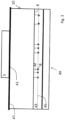
- Figure 3 discloses a molecular manipulation system according to an embodiment.
- the system is constructed and arranged to have the first surface 8 in the sample holder perpendicular to the propagation direction of a standing wave generated with the acoustic wave generator 5 e.g. a pi ⁇ zo element.
- the acoustic wave generator 5 has a vibration actuating plane 41 perpendicular to the propagation direction of the standing wave, the system being constructed and arranged to have the vibration actuation plane 41 substantially parallel to the first surface 8 in the sample holder 10.
- the sample holder 10 comprises a flow cell having a channel 43 with the first surface 8 along the inside of the channel 43.
- the acoustic wave is used to exert a force on the microbeads B stretching the molecules M towards a centerline 45 of the channel 43 when activated.
- the acoustic wave creates a standing wave pushing the beads B away form the first surface 8 in the sample towards the centerline 45.
- a reflector 47 may be provided for illumination of the beads B.
- the reflector 47 may be provided between the sample holder 10 and the molecular manipulation device 5, which together may form a single unit. Illumination may be provided from a direction as depicted by arrow 49.
- the sample holder may be a container holder for holding a replaceable container e.g. a petri dish with the surface provided with the sample perpendicular to the propagation direction of the standing wave in the standing wave.
- a replaceable container e.g. a petri dish with the surface provided with the sample perpendicular to the propagation direction of the standing wave in the standing wave.
- Figure 4a depicts the X, Y movements of the microbeads when the microbeads are freely moving FM and moving with a 6.630 MHz acoustic standing wave AM.
- Figure 4b depicts the X, Y movements of the microbeads FM when the beads are freely moving and when an acoustic wave of 9.567MHz is provided which is resonating, but this frequency is not favorable for pushing. Thereby streaming is dominant, in the flow channel which presses the molecules along the first surface. Clearly visible is the influence of an acoustic wave on the movements of the microbeads.
- the detector device to detect a position of the microbead may also be a detector to detect a position of multiple microbeads that are connected in the sample to multiple molecules.
- the apparatus may become very sensitive for detecting concentrations of a particular molecule in the sample and/or for detecting the influence of certain proteins on the length of the molecules.
- the apparatus may also be used to measure the presents and or concentration of particular molecules interacting with the molecules that are located between the cover glass and the microbead.
- the invention may take the form of a computer program containing one or more sequences of machine-readable instructions describing a method as disclosed above, or a data storage medium (e.g. semiconductor memory, magnetic or optical disk) having such a computer program stored therein.
- a data storage medium e.g. semiconductor memory, magnetic or optical disk
Landscapes
- Chemical & Material Sciences (AREA)
- Physics & Mathematics (AREA)
- Life Sciences & Earth Sciences (AREA)
- Analytical Chemistry (AREA)
- Organic Chemistry (AREA)
- Health & Medical Sciences (AREA)
- General Physics & Mathematics (AREA)
- Proteomics, Peptides & Aminoacids (AREA)
- General Health & Medical Sciences (AREA)
- Immunology (AREA)
- Zoology (AREA)
- Biochemistry (AREA)
- Engineering & Computer Science (AREA)
- Wood Science & Technology (AREA)
- Optics & Photonics (AREA)
- Molecular Biology (AREA)
- Microbiology (AREA)
- Acoustics & Sound (AREA)
- Biotechnology (AREA)
- Biophysics (AREA)
- Bioinformatics & Cheminformatics (AREA)
- General Engineering & Computer Science (AREA)
- Genetics & Genomics (AREA)
- Pathology (AREA)
- Investigating Or Analyzing Materials By The Use Of Ultrasonic Waves (AREA)
- Investigating, Analyzing Materials By Fluorescence Or Luminescence (AREA)
- Apparatus Associated With Microorganisms And Enzymes (AREA)
Description
- The invention relates to a molecular manipulation system for investigating molecules, the system comprising:
- a sample holder constructed for holding a sample comprising a plurality of (bio)molecules attached on one side to a surface in the sample holder and on another side attached to a microbead of a plurality of microbeads; and,
- a molecular manipulation device for manipulating the molecules by exerting a force on the microbeads.
- The ability to observe the properties of molecules may be a great tool in biology, chemistry and physics. Early methods relied on electronic signals such as the patchclamp and electron microscopy. With the discovery of the green fluorescence protein (GFP), single biomolecules at work may be visualized in both in vitro and in vivo. A whole field of single molecule biophysics has emerged, dedicated to exploring the physical details of the cell at one molecule at a time. These single molecule experiments have helped us to create insight into the molecular structure and mechanism of protein folding, motor proteins, and DNA and protein interactions.
- In order to learn about the physical properties of molecules, only observing may not be enough, often physical manipulation of the biomolecule of interest can yield additional information. Several techniques allow the manipulation by applying forces to the molecule, such as atomic force microscopy (AFM), and magnetic and optical tweezers. Each of these techniques has its own advantages and drawbacks. For example, in most of these techniques only one molecule is manipulated at the time.
- It may be beneficial to manipulate a plurality of single molecules and investigate their behaviour.
WO2013/051932 therefore discloses a molecular manipulation apparatus for investigating molecules attached on one side to a surface of a sample and on another side to a microbead. The apparatus having a radiation system for providing a radiation beam with a radiation intensity to the sample and the surface of the sample is transmissive for the radiation. The apparatus is provided with a sample holder for holding the sample with its transmissive surface in the beam of radiation such that the plurality of microbeads are pushed by the radiation. The radiation may have a power between 1 MilliWatt and 1 KiloWatt and a wavelength between 150 and 1500nm. The apparatus has a detector for detecting a 3D position of the microbeads; and, a computer programmed for calculating a physical property of the molecules as a function of the 3D position of the plurality of microbeads. -
US2011207238 A1 discloses a reaction chamber having a sample supply space, an acoustic matching layer which is provided at a predetermined region of an inner wall of the reaction chamber that faces another inner wall, and a sensor portion provided within the reaction chamber is employed. Ultrasonic waves are emitted such that a standing wave are generated between the acoustic matching layer and the inner wall of the reaction chamber that faces the acoustic matching layer. - It is an objective of the invention to provide an improved molecular manipulation system for investigation of a plurality of molecules. A molecular manipulation system according to the invention is defined in
claim 1. - The force exerted by the acoustic wave on a microbead may be between 0.1 to 1000 piconewton which is much larger than possible with a laser beam using the same powers. The acoustic waves do not provided a large heat load on the sample as the radiation of the laser may do when applying pushing with the radiation of the laser beam. The heat load may damage the molecules in the sample or may disturb the detector which is not the case if acoustic waves are provided according to the embodiment.
- According to an embodiment the manipulation system comprises a detector device to detect a response of the plurality of microbeads in the sample on the force exerted by the acoustic wave to investigate the molecules attached to the microbeads. The effects of the manipulation of the plurality of molecules may therewith be investigated.
- According to an embodiment the acoustic wave generator has an adjustable frequency to tune the frequency of the acoustic wave to a frequency of an acoustic standing wave. The frequency of the acoustic standing wave is determined by the dimensions of the sample. By having an adjustable frequency the frequency of the acoustic wave may be tuned to the (un)known frequency of the acoustic standing wave. The acoustic standing wave is resonating within the sample holder and thereby exerting a larger force. The force may be a factor more than 100,000 larger than the force of a normal not resonating acoustic wave.
- According to an embodiment the system is constructed and arranged to have the surface in the sample holder perpendicular to the propagation direction of the standing wave generated with the acoustic wave generator. By this construction the molecules attached to the surface will receive a force stretching the molecules in a direction parallel to the propagation direction of the acoustic wave.
- According to an embodiment the acoustic wave generator has a vibration actuating plane perpendicular to the propagation direction of the standing wave, the system being constructed and arranged to have the vibration actuation plane substantially parallel to the surface in the sample holder. By this construction the molecules attached to the surface and microbeads will receive a force stretching the molecules in a direction parallel to the propagation direction of the acoustic wave.
- According to an embodiment the acoustic wave generator is a piëzo element. The piezo may be controlled by an alternating current of a power source to create an acoustic standing wave. Piëzo element's are relatively cheap and may have a fast response time to adjust the force.
- According to an embodiment the sample holder comprises a flow cell having a channel with the surface being along the inside of the channel. The molecules and/or microbeads may be provided by flowing them through channel of the flow cell.
- According to an embodiment the sample holder comprises a container holder for holding a container with the surface provided with the sample perpendicular to the propagation direction of the standing wave. The container with the sample may simply be exchanged from the system in this way.
- According to a further embodiment the detector device comprises a microscope, and the system is constructed and arranged to have a focal plane of the microscope substantially parallel and slightly above the surface provided with the sample to detect the microbeads attached with the molecules to the surface. The microscope provides an easy way to detect the microbeads. Preferably, air is present between the microscope and the sample.
- According to an embodiment the microscope is provided with a detector to produce a digital image of the focal plane and the system is provided with a calculation device to calculate a position of the microbeads in a direction perpendicular to the focal plane by processing of an interference pattern caused by microbeads which are not in focus. By having a sensor producing a digital image the position of the microbeads may be digitally calculated.
- According to an embodiment the microscope is provided with a detector to produce a digital image of the focal plane and the system is provided with a calculation device to calculate a position of the microbeads in a direction parallel to the focal plane.
- According to an embodiment the microscope is provided with a detector to produce a digital image of the focal plane and the system is provided with a processing device to provide a quantitative analysis of the microbeads in the sample. Quantitative analyses may be useful if, for example it is necessary to determine a concentration of a particular molecule in the sample or for example it is necessary to extract quantitative physical information of a particular molecule in the sample.
- According to an embodiment the system comprises an illumination system for illuminating the sample in the sample holder. Illuminating the sample improves imaging of the microbeads. A reflector may be provided in the system to reflect the radiation of the illuminator towards the sample.
- According to an embodiment the acoustic wave generator has an adjustable frequency to tune the frequency of the acoustic wave to one of the resonating frequencies of the acoustic standing wave. When the frequency is set to a resonating frequency where pushing is not favorable this may result in acoustic streaming of the liquid in the sample. This may be helpful in the process of connecting the molecules to the surface and on connecting the microbeads to the molecules and the mixing of the fluids in the sample.
- According to an embodiment the molecular manipulation system is provided with a reflector for illumination of the beads. The reflector being provided between the sample and the molecular manipulation device. By providing the illumination from the other side of the acoustic wave generator the reflector reflects the illumination back to the sample.
- According to an embodiment the sample holder and the manipulation device are provided as a single unit. The manipulation system may function as a lab on chip giving it a very versatile use.
- According to the invention there is provided a method of investigating molecules as defined in
claim 8. - According to an embodiment the microbeads are made of thermoplastics, thermosetting polymers or silica. The force exerted by the acoustic standing wave scale with the third power of the radius. Therefore the size is an important factor in the manipulation. No magnetic material is required in the microbeads which would be the case if a magnetic force is used. The microbeads made of thermoplastics, thermosetting polymers or silica are easy to produce and relatively cheap.
- According to an embodiment the method comprises providing an additional molecule in the sample and detecting a response of the plurality of microbeads in the sample comprises detecting an influence of the additional molecules on the molecules attached to the microbeads. The manipulation system may be used to determine the influence of additional other molecules on the molecule under investigation. If the other molecules are provided they may have influence on for example the length of the molecule under investigation or the strength with which the molecule under investigation is attached, which may be measured with the manipulation system.
- Embodiments of the invention will now be described, by way of example only, with reference to the accompanying schematic drawings in which corresponding reference symbols indicate corresponding parts, and in which:
-
Figure 1 depicts a schematic drawing of the molecular manipulation apparatus according to an embodiment; -
Figures 2a and2b depict how the molecular manipulation apparatus is working; -
Figure 3 discloses a molecular manipulation system according to an embodiment of the invention; -
Figure 4a depicts the X, Y movements of the microbeads when the microbeads are freely moving and with a 6.630 MHz acoustic standing wave (figure 4a ); and, -
Figure 4b depicts the X, Y movements of the microbeads FM when the beads are freely moving and when an acoustic wave of 9.567MHz is provided a resonance frequency where streaming is favorable, thereby providing streaming in the flow channel. -
Figure 1 depicts a schematic drawing of themolecular investigation system 1 for investigating molecules according to an embodiment. Amolecular manipulation device 3 may be provided with anacoustic wave generator 5, a transducer(e.g. a piëzo element or a voice coil actuator) connected with apower source 7 for generating an acoustic wave. Asample 9 comprising a plurality of molecules attached on one side to afirst surface 8 in thesample holder 10 and on another side attached to a microbead of a plurality of microbeads may be held by asample holder 10 with itssecond surface 12 against theacoustic wave generator 5. - The
power source 7 may provide an alternating current with an adjustable frequency to tune the frequency of the acoustic wave between 0 to 20 MHz to a frequency of an acoustic standing wave. The Voltage of thepower source 7 may also be tuned to adjust the amplitude of the acoustic wave. The acoustic standing wave is resonating within the sample holder and thereby exerting a larger force. The force may be a factor more than 100,000 larger than the force of a normal not resonating acoustic wave. The force of the acoustic wave on a microbead may be between 0.1 to 1000 piconewton, preferably between 1 to 100 piconewton. The acoustic standing wave created over the flowcell will push the beads that are in this flowcell to the nod of the standing wave. - The adjustable frequency of the acoustic wave may be tuned to a resonance frequency of the acoustic standing wave, where streaming dominates, so as to create a streaming in the fluid of the sample, to mix the sample. A resonance frequency of the standing wave, where pushing is less favorable, will create mixing in the sample. This may be helpful in the process of connecting the molecules to the surface and on connecting the microbeads to the molecules.
- The
sample 9 may be held by asample holder 10 with itssecond surface 12 against theacoustic wave generator 5. Amicroscope objective 11 may be used in the detector device for imaging an image of the microbeads on thedetector 23. The objective is, preferably, of the air type, i.e. air is present between the objective 11 and the sample to insulate the vibrations in the sample from themicroscope objective 11 such that the forces exerted by the standing wave are maximized and no vibrations are vibrating the objective. - Illumination of the
sample 9 may be accomplished by an illumination system provided with a lightsource e.g. LED 15 andilluminator lens 19. The illumination beam may be coupled into themicroscopic objective 11 using in-coupling optics, for example abeam splitter 17. The illumination beam may illuminate thesample 9. A reflector may be provided between thesample 9 and theacoustic wave generator 5 to reflect the illumination beam back towards thedetector 23. - The light collected by the objective 11 may be imaged on the
detector 23, for example a CMOS camera. The CMOS camera may be operable connected to acomputer 24 for analyzing the image and/or calculating a physical property of the molecule. Thecomputer 24 may be programmed to: - calculate a 2D position of the microbeads in the focal plane;
- calculate a position of the microbeads in a direction perpendicular to the focal plane by processing of an interference pattern caused by microbeads which are not in focus;
- calculate a position of the microbeads in a direction parallel to the focal plane; and/or,
- provide a quantitative analysis of the microbeads in the sample.
- A
sample 9, not in accordance with the claimed invention, e.g. a simple flow cell may be made by separating a cover glass 27 (0.20x25x25mm fused quarts Vitrosil 077®) and microscope slide 29 (1x75x25mm fused quarts Vitrosil 077) with a layer of parafilm 31 (Seefigure 2a and2b ). A plurality of molecules e.g. DNA molecules (1000 bps) M are at one end attached (e.g. tethered) to thefirst surface 8 via a first connector e.g. adig 33 connecting to a secondconnector e.g. anti-dig 35. The other end of the molecule M may be attached (e.g. tethered) to a microbead B of a plurality of microbeads via a thirdconnector e.g. biotin 39 binding with a fourthconnector e.g. streptavadin 37. - According to the invention, the sample is prepared from a flow cell that is made out of one piece of material with a channel in the middle. A plurality of molecules e.g. DNA molecules (1000 bps) may be at one end attached (e.g. tethered) to a first surface of the channel and via a first connector e.g. a dig connected to a second connector e.g. anti-dig. The other end of the molecule may be attached (e.g. tethered) to a microbead of a plurality of microbeads via a third connector e.g. biotin binding with a fourth connector e.g. streptavidin. The flow cell may be provided with the molecules, the first, second, third and fourth connector and the beads by flowing them through the flow channel and let them react in the channel to prepare the sample. An advantage of using a flow cell made out of one piece is that it is more rigid and therefore acoustically a better resonance may be present increasing the forces that may be exerted on the beads.
- The sample prepared from a flow cell made out of one piece of material with a channel in the middle may also be provided with the vibration generator e.g. the piëzo element mounted on the sample. In this way we prepare a lab on chip design. To prevent sticking of the DNA, the surface of the flow cell may be coated with casein. The microbead B tethered to the DNA molecule may serve a double purpose: first as a handle to apply a
force 25 to the DNA with theacoustic wave 13 and second as a probe to detect the DNA's response to that appliedforce 25. The physical property of the DNA molecules M may be determined by detecting the position of the microbead B in 3 dimensions over time with the detectordevice comprising objective 11 and camera 23 (infigure 1 ) and in response to theforce 25 generated by theacoustic wave 13. The microbeads B and molecules M may be surrounded by water in thesample 9. An advantage of the apparatus is that it may be used with a large number of different microbeads. In magnetic manipulation apparatus one may be bound to the use of magnetic microbeads whereas in our system there is more freedom of the used microbeads of different materials. - We may also investigate direct protein-antibody interactions in the sample. In that case there may be a direct connection between the
streptavidin 37 and the anti-dig 35 offigure 2b without the molecule "M", thebiotin 39 and thedig 33 offigure 2b . The later being helpful if direct interactions are being investigated. - The center position of the microbead B may be calculated by the
computer 24 for every image of thedetector 23 to track the end-to-end length of the DNA molecule M over time. Since the size of the microbead B may be in the order of a wavelength the point spread function (PSF) may be imaged on thedetector 23. To detect the center of the PSF (x, y) a cross correlation algorithm may be used, that achieves sub pixel resolution even when the PSF center is not more than a few pixels. Although a single measurement of the microbead position may directly yield information on the state of the DNA, multiple measurements may lead to a distribution that may be used to investigate the physical properties of the DNA molecule e.g. the length as well as length changes (for example induced by proteins). A typical value that describes the size of the distribution in relation to the average positions x and y may be the root mean square motion (RMS) and is given by equation 1.1.
- In addition to the position of the microbead in x and y, the changes in height of the microbead (z) may also be recorded. And in contrast to the x, y position, the microbead's height may be a direct measurement of the DNA's length. The height may be determined by determining the shape of the PSF that is dependent on the distance from the sample to the detector or to calculate a z position of the microbead by the interference pattern image caused by an unfocused microbead. Hence, a change in height of the microbead leads to a change in the PSF. In order to relate the measured PSF to the changes in height, a look up table may be used (LUT, a library that contains the radial profile as a function of the microbeads height). The LUTs may be made by moving the sample over a known distance, using a piezo stage, and storing the radial profile of the microbead. To obtain the changes in height during a measurement, the measured radial profile may be compared to the profiles stored in the LUT. By interpolating between and averaging over multiple radial profiles, a detection accuracy of < 5 nm may be achieved at an effective frame rate of 25 Hz.
- To maximize the exerted force and minimize the amount of energy in the acoustic wave necessary to achieve desirable forces, selecting the proper material and microbead size may be very important. The microbeads may therefore be made of thermoplastics and thermosetting polymers or silica. Double stranded DNA starts to melt and convert into single stranded molecules at a force of around 65 piconewtons (pN) (depending on salt concentrations). Therefore, the molecular manipulation system may ideally be able to achieve forces of several tens of piconewtons to be able to fully stretch double stranded DNA.
-
Figure 3 discloses a molecular manipulation system according to an embodiment. The system is constructed and arranged to have thefirst surface 8 in the sample holder perpendicular to the propagation direction of a standing wave generated with theacoustic wave generator 5 e.g. a piëzo element. Theacoustic wave generator 5 has avibration actuating plane 41 perpendicular to the propagation direction of the standing wave, the system being constructed and arranged to have thevibration actuation plane 41 substantially parallel to thefirst surface 8 in thesample holder 10. - The
sample holder 10 comprises a flow cell having achannel 43 with thefirst surface 8 along the inside of thechannel 43. The acoustic wave is used to exert a force on the microbeads B stretching the molecules M towards acenterline 45 of thechannel 43 when activated. The acoustic wave creates a standing wave pushing the beads B away form thefirst surface 8 in the sample towards thecenterline 45. Areflector 47 may be provided for illumination of the beads B. Thereflector 47 may be provided between thesample holder 10 and themolecular manipulation device 5, which together may form a single unit. Illumination may be provided from a direction as depicted byarrow 49. - Alternatively, not in accordance with the claimed invention, the sample holder may be a container holder for holding a replaceable container e.g. a petri dish with the surface provided with the sample perpendicular to the propagation direction of the standing wave in the standing wave. In this embodiment it is rather easy to replace the container with another container.
-
Figure 4a depicts the X, Y movements of the microbeads when the microbeads are freely moving FM and moving with a 6.630 MHz acoustic standing wave AM. -
Figure 4b depicts the X, Y movements of the microbeads FM when the beads are freely moving and when an acoustic wave of 9.567MHz is provided which is resonating, but this frequency is not favorable for pushing. Thereby streaming is dominant, in the flow channel which presses the molecules along the first surface. Clearly visible is the influence of an acoustic wave on the movements of the microbeads. - The detector device to detect a position of the microbead may also be a detector to detect a position of multiple microbeads that are connected in the sample to multiple molecules. By quantitive analysis of the microbeads and their position in the sample the apparatus may become very sensitive for detecting concentrations of a particular molecule in the sample and/or for detecting the influence of certain proteins on the length of the molecules. The apparatus may also be used to measure the presents and or concentration of particular molecules interacting with the molecules that are located between the cover glass and the microbead.
- While specific embodiments of the invention have been described above, it will be appreciated that the invention may be practiced otherwise than as described. For example, the invention may take the form of a computer program containing one or more sequences of machine-readable instructions describing a method as disclosed above, or a data storage medium (e.g. semiconductor memory, magnetic or optical disk) having such a computer program stored therein.
- The descriptions above are intended to be illustrative, not limiting. Thus, it will be apparent to one skilled in the art that modifications may be made to the invention as described without departing from the scope of the claims set out below.
Claims (10)
- A molecular manipulation system for investigating molecules, the system comprising:a flow cell made of one piece of material with a channel (43) in the middle having a first surface (8) with second connectors (35), wherein the flow cell is suitable for holding a sample comprising a plurality of molecules (M) with first connectors (33) attached on one side to the second connectors (35) on the first surface (8) and on another side attached to a microbead (B) of a plurality of microbeads; anda molecular manipulation device (3) comprising an acoustic wave generator (5) configured to generate an acoustic standing wave for pushing the microbeads (B) in the sample away from the first surface (8) towards a centerline (45) of the channel (43) and exerting a force on the microbeads in the sample stretching the molecules towards the centerline (45).
- The molecular manipulation system according to claim 1, wherein the connectors comprise a dig and anti-dig.
- The molecular manipulation system according to claim 1,wherein the flow cell and the manipulation device are provided as a single unit to form a lab on chip.
- The molecular manipulation system according to any of the preceding claims, wherein the detector device comprises a microscope, and the system is constructed and arranged to have a focal plane of the microscope substantially parallel and slightly above the first surface provided with the sample to detect the microbeads attached with the molecules to the first surface.
- The molecular manipulation system according to claim 4, wherein the detector device comprises a detector to produce a digital image of the focal plane and the system is provided with a calculation device to calculate a position of the microbeads in a direction perpendicular to the focal plane by processing of an interference pattern caused by microbeads which are not in focus.
- The molecular manipulation system according to claims 4 or 5, wherein the detector device comprises a detector to produce a digital image of the focal plane and the system is provided with a calculation device to calculate a position of the microbeads in a direction parallel to the focal plane.
- The molecular manipulation system according to any of the preceding claims, wherein the acoustic wave generator has an adjustable frequency to tune the frequency of the acoustic wave to a frequency of the acoustic standing wave, where mixing is more favourable, in comparison with pushing, to mix the sample.
- A method of manipulating molecules comprising:providing a plurality of molecules with first connectors to a sample in a flow cell made of one piece of material with a channel in the middle having a first surface with second connectors;connecting the molecules with the first connectors on one side to the second connectors on the first surface and with another side to a microbead of a plurality of microbeads; andgenerating an acoustic standing wave with an acoustic wave generator pushing the microbeads in the sample away from the first surface in the sample towards a centerline of the channel and exerting a force on the microbeads in the sample stretching the molecules towards the centerline.
- The method according to claim 8, wherein the force is at least several tens of piconewtons.
- The method according to claim 8 or 9, wherein the force is at least 65 piconewtons.
Applications Claiming Priority (2)
| Application Number | Priority Date | Filing Date | Title |
|---|---|---|---|
| NL2010960A NL2010960C2 (en) | 2013-06-12 | 2013-06-12 | Molecular manipulation system and method. |
| PCT/NL2014/050377 WO2014200341A1 (en) | 2013-06-12 | 2014-06-11 | Molecular manipulation system and method |
Publications (2)
| Publication Number | Publication Date |
|---|---|
| EP3008506A1 EP3008506A1 (en) | 2016-04-20 |
| EP3008506B1 true EP3008506B1 (en) | 2023-09-20 |
Family
ID=48951554
Family Applications (1)
| Application Number | Title | Priority Date | Filing Date |
|---|---|---|---|
| EP14737025.8A Active EP3008506B1 (en) | 2013-06-12 | 2014-06-11 | Molecular manipulation system and method |
Country Status (4)
| Country | Link |
|---|---|
| US (1) | US10941437B2 (en) |
| EP (1) | EP3008506B1 (en) |
| NL (1) | NL2010960C2 (en) |
| WO (1) | WO2014200341A1 (en) |
Families Citing this family (21)
| Publication number | Priority date | Publication date | Assignee | Title |
|---|---|---|---|---|
| NL2017705B1 (en) * | 2016-11-02 | 2018-05-18 | Lumicks Tech B V | Method and system for studying biological cells |
| NL2020257B1 (en) | 2018-01-09 | 2019-07-15 | Stichting Vu | Methods and systems for supercoiling DNA |
| NL2020377B1 (en) | 2018-02-05 | 2019-08-14 | Lumicks Tech B V | Methods and devices for determining a guest structure on a host structure |
| NL2020862B1 (en) | 2018-05-02 | 2019-11-12 | Lumicks Tech B V | Probing mechanical properties of biological matter |
| NL2024155B1 (en) | 2019-11-04 | 2021-07-19 | Lumicks Ca Holding B V | Determining interactions between cells based on force spectroscopy |
| NL2026048B1 (en) | 2020-07-10 | 2022-03-15 | Lumicks Ca Holding B V | Methods and systems for manipulating a particle |
| NL2026383B1 (en) | 2020-08-31 | 2022-04-29 | Lumicks Ca Holding B V | Method and system for studying objects, in particular biological cells |
| NL2026393B1 (en) | 2020-09-01 | 2022-05-04 | Lumicks Ca Holding B V | Sorting of cellular bodies based on force spectroscopy |
| NL2026531B1 (en) | 2020-09-24 | 2022-05-30 | Lumicks Ca Holding B V | Methods and systems for detecting particle occupancy |
| NL2026548B1 (en) | 2020-09-25 | 2022-05-30 | Lumicks Ca Holding B V | Determining interactions between cellular bodies and a functionalized wall surface |
| NL2026628B1 (en) | 2020-10-05 | 2022-06-03 | Lumicks Ca Holding B V | Determining physical properties of cellular bodies based on acoustic force spectroscopy |
| NL2026714B1 (en) | 2020-10-20 | 2022-06-16 | Lumicks Ca Holding B V | Improved detection of lymphocyte - target cell interaction |
| CN112945918A (en) * | 2021-01-28 | 2021-06-11 | 中国科学院深圳先进技术研究院 | Cell ultrasonic nerve regulation and control system |
| NL2028594B1 (en) | 2021-06-30 | 2023-01-10 | Lumicks Ca Holding B V | Method for measuring fluid temperature in an acoustic-based particle manipulation device |
| NL2028593B1 (en) | 2021-06-30 | 2023-01-10 | Lumicks Ca Holding B V | Method and system for characterizing an acoustic-based particle manipulation device |
| NL2028613B1 (en) | 2021-07-02 | 2023-01-10 | Lumicks Ca Holding B V | Local area photoactivation |
| NL2029685B1 (en) | 2021-11-09 | 2023-06-05 | Lumicks Ca Holding B V | Detection of interacting cellular bodies |
| WO2023126471A1 (en) | 2021-12-31 | 2023-07-06 | Lumicks Ca Holding B.V. | Methods for identifying receptors and cellular avidities |
| NL2030386B1 (en) | 2021-12-31 | 2023-07-07 | Lumicks Ca Holding B V | Methods for identifying receptors and cellular avidities |
| EP4522644A1 (en) | 2022-05-13 | 2025-03-19 | LUMICKS CA Holding B.V. | Means and methods for determining cellular avidity |
| WO2023218017A1 (en) | 2022-05-13 | 2023-11-16 | Lumicks Ca Holding B.V. | Means and methods for determining cellular avidity |
Citations (3)
| Publication number | Priority date | Publication date | Assignee | Title |
|---|---|---|---|---|
| US6086821A (en) * | 1999-03-29 | 2000-07-11 | The United States Of America As Represented By The Secretary Of The Navy | Ultrasonic force differentiation assay |
| US6216538B1 (en) * | 1992-12-02 | 2001-04-17 | Hitachi, Ltd. | Particle handling apparatus for handling particles in fluid by acoustic radiation pressure |
| US20110207238A1 (en) * | 2010-02-25 | 2011-08-25 | Fujifilm Corporation | Biological substance analyzing method, and biological substance analyzing cell, biological substance analyzing chip, and biological substance analyzing apparatus employed in the biological substance analyzing method |
Family Cites Families (12)
| Publication number | Priority date | Publication date | Assignee | Title |
|---|---|---|---|---|
| US5394268A (en) * | 1993-02-05 | 1995-02-28 | Carnegie Mellon University | Field synthesis and optical subsectioning for standing wave microscopy |
| JPH09292572A (en) * | 1996-04-24 | 1997-11-11 | Nikon Corp | Epi-illumination fluorescence microscope |
| US7763475B2 (en) * | 1999-04-22 | 2010-07-27 | Inverness Medical Switzerland Gmbh | Measurement and use of molecular interactions |
| DE10017823B4 (en) * | 2000-04-10 | 2004-08-26 | Till I.D. Gmbh | Microscopic illuminator |
| AU2001293747A1 (en) * | 2000-08-11 | 2002-02-25 | Nanotype Gmbh | Method and device for characterising and/or for detecting a bonding complex |
| CA2424941A1 (en) * | 2000-10-10 | 2002-04-18 | Aviva Biosciences Corporation | An integrated biochip system for sample preparation and analysis |
| JP4434649B2 (en) * | 2003-03-27 | 2010-03-17 | 株式会社Eci | Observation instrument and observation method using the same |
| US9696298B2 (en) * | 2003-04-03 | 2017-07-04 | Enzo Life Sciences, Inc. | Multisignal reagents for labeling analytes |
| CA2643767A1 (en) * | 2006-05-03 | 2007-11-08 | Ncl New Concept Lab Gmbh | Device and method for chemical, biochemical, biological and physical analysis, reaction, assay and more |
| WO2010040062A2 (en) * | 2008-10-02 | 2010-04-08 | Advanced Throughput Ltd.Co. | Nanoparticle labeling reagents and methods of use |
| CN103025859A (en) * | 2010-05-25 | 2013-04-03 | 阿尔利克斯公司 | Methods and apparatuses for detection of positional freedom of particles in biological and chemical analyses and applications in immunodiagnostics |
| WO2013051932A1 (en) * | 2011-10-03 | 2013-04-11 | Vereniging Voor Christelijk Hoger Onderwijs,Wetenschappelijk Onderzoek En Patiëntenzorg | Molecular manipulation apparatus and method for investigating a plurality of molecules |
-
2013
- 2013-06-12 NL NL2010960A patent/NL2010960C2/en not_active IP Right Cessation
-
2014
- 2014-06-11 EP EP14737025.8A patent/EP3008506B1/en active Active
- 2014-06-11 WO PCT/NL2014/050377 patent/WO2014200341A1/en not_active Ceased
- 2014-06-11 US US14/898,112 patent/US10941437B2/en active Active
Patent Citations (3)
| Publication number | Priority date | Publication date | Assignee | Title |
|---|---|---|---|---|
| US6216538B1 (en) * | 1992-12-02 | 2001-04-17 | Hitachi, Ltd. | Particle handling apparatus for handling particles in fluid by acoustic radiation pressure |
| US6086821A (en) * | 1999-03-29 | 2000-07-11 | The United States Of America As Represented By The Secretary Of The Navy | Ultrasonic force differentiation assay |
| US20110207238A1 (en) * | 2010-02-25 | 2011-08-25 | Fujifilm Corporation | Biological substance analyzing method, and biological substance analyzing cell, biological substance analyzing chip, and biological substance analyzing apparatus employed in the biological substance analyzing method |
Also Published As
| Publication number | Publication date |
|---|---|
| US10941437B2 (en) | 2021-03-09 |
| EP3008506A1 (en) | 2016-04-20 |
| NL2010960C2 (en) | 2014-12-15 |
| WO2014200341A1 (en) | 2014-12-18 |
| US20160138095A1 (en) | 2016-05-19 |
Similar Documents
| Publication | Publication Date | Title |
|---|---|---|
| US10941437B2 (en) | Molecular manipulation system and method | |
| Ohlinger et al. | Optically trapped gold nanoparticle enables listening at the microscale | |
| US10795144B2 (en) | Microscopy with structured plane illumination and point accumulation for imaging and nanoscale topography | |
| CN103257130B (en) | Stimulated radiation loss micro imaging system | |
| US9664614B2 (en) | Method for high resolution sum-frequency generation and infrared microscopy | |
| EP3532853A1 (en) | Method and apparatus for chemical imaging atomic force microscope infrared spectroscopy | |
| WO2010065131A2 (en) | High frequenct deflection measurement of ir absorption | |
| EP2795346B1 (en) | Optical and atomic force microscopy integrated system for multi-probe spectroscopy measurements applied in a wide spatial region with an extended range of force sensitivity. | |
| CN102998290A (en) | Fluorescent lifetime microimaging system | |
| US20210247291A1 (en) | Probing mechanical properties of biological matter | |
| Huang et al. | Recent advances in surface plasmon resonance microscopy | |
| Magazzú et al. | Optical tweezers: A non-destructive tool for soft and biomaterial investigations | |
| JP6263887B2 (en) | Surface plasmon enhanced fluorescence measurement method and surface plasmon enhanced fluorescence measurement apparatus | |
| Viana et al. | Dynamic light scattering from an optically trapped microsphere | |
| JP2022520085A (en) | Equipment, systems and methods for microscope sample holders | |
| Möller | Acoustically driven particle transport in fluid chambers | |
| US20240316550A1 (en) | Method and system for characterizing an acoustic-based particle manipulation device | |
| EP4226141B1 (en) | Determining physical properties of cellular bodies based on acoustic force spectroscopy | |
| EP1901057A1 (en) | Substance information acquisition method and substance information measurement device using evanescent light, and base arrangement decision method and device | |
| Torres et al. | Optical micro-elastography with magnetic excitation for high frequency rheological characterization of soft media | |
| Koops et al. | An approach towards 3D sensitive AFM cantilevers | |
| WO2013051932A1 (en) | Molecular manipulation apparatus and method for investigating a plurality of molecules | |
| NL2028594B1 (en) | Method for measuring fluid temperature in an acoustic-based particle manipulation device | |
| WO2025228413A1 (en) | Optically detected magnetic resonance with light-sheet microscopy | |
| CN114322863B (en) | Method for far-field illumination and detection of objects that break through diffraction limits |
Legal Events
| Date | Code | Title | Description |
|---|---|---|---|
| PUAI | Public reference made under article 153(3) epc to a published international application that has entered the european phase |
Free format text: ORIGINAL CODE: 0009012 |
|
| 17P | Request for examination filed |
Effective date: 20160112 |
|
| AK | Designated contracting states |
Kind code of ref document: A1 Designated state(s): AL AT BE BG CH CY CZ DE DK EE ES FI FR GB GR HR HU IE IS IT LI LT LU LV MC MK MT NL NO PL PT RO RS SE SI SK SM TR |
|
| AX | Request for extension of the european patent |
Extension state: BA ME |
|
| DAX | Request for extension of the european patent (deleted) | ||
| RAP1 | Party data changed (applicant data changed or rights of an application transferred) |
Owner name: AFS TECHNOLOGIES B.V. |
|
| STAA | Information on the status of an ep patent application or granted ep patent |
Free format text: STATUS: EXAMINATION IS IN PROGRESS |
|
| 17Q | First examination report despatched |
Effective date: 20190927 |
|
| RIN1 | Information on inventor provided before grant (corrected) |
Inventor name: KAMSMA, DOUWE Inventor name: SITTERS, GERRIT Inventor name: WUITE, GIJS JAN LODEWIJK Inventor name: PETERMAN, ERWIN JOHANNES GERARD |
|
| RAP3 | Party data changed (applicant data changed or rights of an application transferred) |
Owner name: AFS TECHNOLOGIES B.V. |
|
| RAP1 | Party data changed (applicant data changed or rights of an application transferred) |
Owner name: LUMICKS CA HOLDING B.V. |
|
| GRAP | Despatch of communication of intention to grant a patent |
Free format text: ORIGINAL CODE: EPIDOSNIGR1 |
|
| STAA | Information on the status of an ep patent application or granted ep patent |
Free format text: STATUS: GRANT OF PATENT IS INTENDED |
|
| INTG | Intention to grant announced |
Effective date: 20230602 |
|
| P01 | Opt-out of the competence of the unified patent court (upc) registered |
Effective date: 20230525 |
|
| GRAS | Grant fee paid |
Free format text: ORIGINAL CODE: EPIDOSNIGR3 |
|
| GRAA | (expected) grant |
Free format text: ORIGINAL CODE: 0009210 |
|
| STAA | Information on the status of an ep patent application or granted ep patent |
Free format text: STATUS: THE PATENT HAS BEEN GRANTED |
|
| AK | Designated contracting states |
Kind code of ref document: B1 Designated state(s): AL AT BE BG CH CY CZ DE DK EE ES FI FR GB GR HR HU IE IS IT LI LT LU LV MC MK MT NL NO PL PT RO RS SE SI SK SM TR |
|
| REG | Reference to a national code |
Ref country code: GB Ref legal event code: FG4D |
|
| REG | Reference to a national code |
Ref country code: CH Ref legal event code: EP |
|
| REG | Reference to a national code |
Ref country code: DE Ref legal event code: R096 Ref document number: 602014088365 Country of ref document: DE |
|
| REG | Reference to a national code |
Ref country code: IE Ref legal event code: FG4D |
|
| REG | Reference to a national code |
Ref country code: NL Ref legal event code: FP |
|
| REG | Reference to a national code |
Ref country code: LT Ref legal event code: MG9D |
|
| PG25 | Lapsed in a contracting state [announced via postgrant information from national office to epo] |
Ref country code: GR Free format text: LAPSE BECAUSE OF FAILURE TO SUBMIT A TRANSLATION OF THE DESCRIPTION OR TO PAY THE FEE WITHIN THE PRESCRIBED TIME-LIMIT Effective date: 20231221 |
|
| PG25 | Lapsed in a contracting state [announced via postgrant information from national office to epo] |
Ref country code: SE Free format text: LAPSE BECAUSE OF FAILURE TO SUBMIT A TRANSLATION OF THE DESCRIPTION OR TO PAY THE FEE WITHIN THE PRESCRIBED TIME-LIMIT Effective date: 20230920 Ref country code: RS Free format text: LAPSE BECAUSE OF FAILURE TO SUBMIT A TRANSLATION OF THE DESCRIPTION OR TO PAY THE FEE WITHIN THE PRESCRIBED TIME-LIMIT Effective date: 20230920 Ref country code: NO Free format text: LAPSE BECAUSE OF FAILURE TO SUBMIT A TRANSLATION OF THE DESCRIPTION OR TO PAY THE FEE WITHIN THE PRESCRIBED TIME-LIMIT Effective date: 20231220 Ref country code: LV Free format text: LAPSE BECAUSE OF FAILURE TO SUBMIT A TRANSLATION OF THE DESCRIPTION OR TO PAY THE FEE WITHIN THE PRESCRIBED TIME-LIMIT Effective date: 20230920 Ref country code: LT Free format text: LAPSE BECAUSE OF FAILURE TO SUBMIT A TRANSLATION OF THE DESCRIPTION OR TO PAY THE FEE WITHIN THE PRESCRIBED TIME-LIMIT Effective date: 20230920 Ref country code: HR Free format text: LAPSE BECAUSE OF FAILURE TO SUBMIT A TRANSLATION OF THE DESCRIPTION OR TO PAY THE FEE WITHIN THE PRESCRIBED TIME-LIMIT Effective date: 20230920 Ref country code: GR Free format text: LAPSE BECAUSE OF FAILURE TO SUBMIT A TRANSLATION OF THE DESCRIPTION OR TO PAY THE FEE WITHIN THE PRESCRIBED TIME-LIMIT Effective date: 20231221 Ref country code: FI Free format text: LAPSE BECAUSE OF FAILURE TO SUBMIT A TRANSLATION OF THE DESCRIPTION OR TO PAY THE FEE WITHIN THE PRESCRIBED TIME-LIMIT Effective date: 20230920 |
|
| REG | Reference to a national code |
Ref country code: AT Ref legal event code: MK05 Ref document number: 1613836 Country of ref document: AT Kind code of ref document: T Effective date: 20230920 |
|
| PG25 | Lapsed in a contracting state [announced via postgrant information from national office to epo] |
Ref country code: IS Free format text: LAPSE BECAUSE OF FAILURE TO SUBMIT A TRANSLATION OF THE DESCRIPTION OR TO PAY THE FEE WITHIN THE PRESCRIBED TIME-LIMIT Effective date: 20240120 |
|
| PG25 | Lapsed in a contracting state [announced via postgrant information from national office to epo] |
Ref country code: AT Free format text: LAPSE BECAUSE OF FAILURE TO SUBMIT A TRANSLATION OF THE DESCRIPTION OR TO PAY THE FEE WITHIN THE PRESCRIBED TIME-LIMIT Effective date: 20230920 |
|
| PG25 | Lapsed in a contracting state [announced via postgrant information from national office to epo] |
Ref country code: ES Free format text: LAPSE BECAUSE OF FAILURE TO SUBMIT A TRANSLATION OF THE DESCRIPTION OR TO PAY THE FEE WITHIN THE PRESCRIBED TIME-LIMIT Effective date: 20230920 |
|
| PG25 | Lapsed in a contracting state [announced via postgrant information from national office to epo] |
Ref country code: SM Free format text: LAPSE BECAUSE OF FAILURE TO SUBMIT A TRANSLATION OF THE DESCRIPTION OR TO PAY THE FEE WITHIN THE PRESCRIBED TIME-LIMIT Effective date: 20230920 Ref country code: RO Free format text: LAPSE BECAUSE OF FAILURE TO SUBMIT A TRANSLATION OF THE DESCRIPTION OR TO PAY THE FEE WITHIN THE PRESCRIBED TIME-LIMIT Effective date: 20230920 Ref country code: IS Free format text: LAPSE BECAUSE OF FAILURE TO SUBMIT A TRANSLATION OF THE DESCRIPTION OR TO PAY THE FEE WITHIN THE PRESCRIBED TIME-LIMIT Effective date: 20240120 Ref country code: ES Free format text: LAPSE BECAUSE OF FAILURE TO SUBMIT A TRANSLATION OF THE DESCRIPTION OR TO PAY THE FEE WITHIN THE PRESCRIBED TIME-LIMIT Effective date: 20230920 Ref country code: EE Free format text: LAPSE BECAUSE OF FAILURE TO SUBMIT A TRANSLATION OF THE DESCRIPTION OR TO PAY THE FEE WITHIN THE PRESCRIBED TIME-LIMIT Effective date: 20230920 Ref country code: CZ Free format text: LAPSE BECAUSE OF FAILURE TO SUBMIT A TRANSLATION OF THE DESCRIPTION OR TO PAY THE FEE WITHIN THE PRESCRIBED TIME-LIMIT Effective date: 20230920 Ref country code: AT Free format text: LAPSE BECAUSE OF FAILURE TO SUBMIT A TRANSLATION OF THE DESCRIPTION OR TO PAY THE FEE WITHIN THE PRESCRIBED TIME-LIMIT Effective date: 20230920 Ref country code: SK Free format text: LAPSE BECAUSE OF FAILURE TO SUBMIT A TRANSLATION OF THE DESCRIPTION OR TO PAY THE FEE WITHIN THE PRESCRIBED TIME-LIMIT Effective date: 20230920 Ref country code: PT Free format text: LAPSE BECAUSE OF FAILURE TO SUBMIT A TRANSLATION OF THE DESCRIPTION OR TO PAY THE FEE WITHIN THE PRESCRIBED TIME-LIMIT Effective date: 20240122 |
|
| PG25 | Lapsed in a contracting state [announced via postgrant information from national office to epo] |
Ref country code: PL Free format text: LAPSE BECAUSE OF FAILURE TO SUBMIT A TRANSLATION OF THE DESCRIPTION OR TO PAY THE FEE WITHIN THE PRESCRIBED TIME-LIMIT Effective date: 20230920 Ref country code: IT Free format text: LAPSE BECAUSE OF FAILURE TO SUBMIT A TRANSLATION OF THE DESCRIPTION OR TO PAY THE FEE WITHIN THE PRESCRIBED TIME-LIMIT Effective date: 20230920 |
|
| REG | Reference to a national code |
Ref country code: DE Ref legal event code: R097 Ref document number: 602014088365 Country of ref document: DE |
|
| PG25 | Lapsed in a contracting state [announced via postgrant information from national office to epo] |
Ref country code: DK Free format text: LAPSE BECAUSE OF FAILURE TO SUBMIT A TRANSLATION OF THE DESCRIPTION OR TO PAY THE FEE WITHIN THE PRESCRIBED TIME-LIMIT Effective date: 20230920 |
|
| PLBE | No opposition filed within time limit |
Free format text: ORIGINAL CODE: 0009261 |
|
| STAA | Information on the status of an ep patent application or granted ep patent |
Free format text: STATUS: NO OPPOSITION FILED WITHIN TIME LIMIT |
|
| PG25 | Lapsed in a contracting state [announced via postgrant information from national office to epo] |
Ref country code: DK Free format text: LAPSE BECAUSE OF FAILURE TO SUBMIT A TRANSLATION OF THE DESCRIPTION OR TO PAY THE FEE WITHIN THE PRESCRIBED TIME-LIMIT Effective date: 20230920 |
|
| 26N | No opposition filed |
Effective date: 20240621 |
|
| PG25 | Lapsed in a contracting state [announced via postgrant information from national office to epo] |
Ref country code: SI Free format text: LAPSE BECAUSE OF FAILURE TO SUBMIT A TRANSLATION OF THE DESCRIPTION OR TO PAY THE FEE WITHIN THE PRESCRIBED TIME-LIMIT Effective date: 20230920 |
|
| PG25 | Lapsed in a contracting state [announced via postgrant information from national office to epo] |
Ref country code: SI Free format text: LAPSE BECAUSE OF FAILURE TO SUBMIT A TRANSLATION OF THE DESCRIPTION OR TO PAY THE FEE WITHIN THE PRESCRIBED TIME-LIMIT Effective date: 20230920 |
|
| PG25 | Lapsed in a contracting state [announced via postgrant information from national office to epo] |
Ref country code: BG Free format text: LAPSE BECAUSE OF FAILURE TO SUBMIT A TRANSLATION OF THE DESCRIPTION OR TO PAY THE FEE WITHIN THE PRESCRIBED TIME-LIMIT Effective date: 20230920 |
|
| PG25 | Lapsed in a contracting state [announced via postgrant information from national office to epo] |
Ref country code: BG Free format text: LAPSE BECAUSE OF FAILURE TO SUBMIT A TRANSLATION OF THE DESCRIPTION OR TO PAY THE FEE WITHIN THE PRESCRIBED TIME-LIMIT Effective date: 20230920 |
|
| PG25 | Lapsed in a contracting state [announced via postgrant information from national office to epo] |
Ref country code: MC Free format text: LAPSE BECAUSE OF FAILURE TO SUBMIT A TRANSLATION OF THE DESCRIPTION OR TO PAY THE FEE WITHIN THE PRESCRIBED TIME-LIMIT Effective date: 20230920 |
|
| REG | Reference to a national code |
Ref country code: CH Ref legal event code: PL |
|
| PG25 | Lapsed in a contracting state [announced via postgrant information from national office to epo] |
Ref country code: LU Free format text: LAPSE BECAUSE OF NON-PAYMENT OF DUE FEES Effective date: 20240611 |
|
| PG25 | Lapsed in a contracting state [announced via postgrant information from national office to epo] |
Ref country code: IE Free format text: LAPSE BECAUSE OF NON-PAYMENT OF DUE FEES Effective date: 20240611 |
|
| PG25 | Lapsed in a contracting state [announced via postgrant information from national office to epo] |
Ref country code: CH Free format text: LAPSE BECAUSE OF NON-PAYMENT OF DUE FEES Effective date: 20240630 Ref country code: BE Free format text: LAPSE BECAUSE OF NON-PAYMENT OF DUE FEES Effective date: 20240630 |
|
| PG25 | Lapsed in a contracting state [announced via postgrant information from national office to epo] |
Ref country code: FR Free format text: LAPSE BECAUSE OF NON-PAYMENT OF DUE FEES Effective date: 20240630 |
|
| REG | Reference to a national code |
Ref country code: BE Ref legal event code: MM Effective date: 20240630 |
|
| PGFP | Annual fee paid to national office [announced via postgrant information from national office to epo] |
Ref country code: DE Payment date: 20250618 Year of fee payment: 12 |
|
| PGFP | Annual fee paid to national office [announced via postgrant information from national office to epo] |
Ref country code: GB Payment date: 20250618 Year of fee payment: 12 |
|
| PGFP | Annual fee paid to national office [announced via postgrant information from national office to epo] |
Ref country code: NL Payment date: 20250618 Year of fee payment: 12 |
|
| PG25 | Lapsed in a contracting state [announced via postgrant information from national office to epo] |
Ref country code: CY Free format text: LAPSE BECAUSE OF FAILURE TO SUBMIT A TRANSLATION OF THE DESCRIPTION OR TO PAY THE FEE WITHIN THE PRESCRIBED TIME-LIMIT; INVALID AB INITIO Effective date: 20140611 |
|
| PG25 | Lapsed in a contracting state [announced via postgrant information from national office to epo] |
Ref country code: HU Free format text: LAPSE BECAUSE OF FAILURE TO SUBMIT A TRANSLATION OF THE DESCRIPTION OR TO PAY THE FEE WITHIN THE PRESCRIBED TIME-LIMIT; INVALID AB INITIO Effective date: 20140611 |