EP3008439B1 - A method of measuring elongation of a fastener with ultrasound, performed by a power tool, and a power tool - Google Patents
A method of measuring elongation of a fastener with ultrasound, performed by a power tool, and a power tool Download PDFInfo
- Publication number
- EP3008439B1 EP3008439B1 EP14728981.3A EP14728981A EP3008439B1 EP 3008439 B1 EP3008439 B1 EP 3008439B1 EP 14728981 A EP14728981 A EP 14728981A EP 3008439 B1 EP3008439 B1 EP 3008439B1
- Authority
- EP
- European Patent Office
- Prior art keywords
- signal
- ultrasonic
- fastener
- signals
- cross
- Prior art date
- Legal status (The legal status is an assumption and is not a legal conclusion. Google has not performed a legal analysis and makes no representation as to the accuracy of the status listed.)
- Active
Links
Images




Classifications
-
- G—PHYSICS
- G01—MEASURING; TESTING
- G01L—MEASURING FORCE, STRESS, TORQUE, WORK, MECHANICAL POWER, MECHANICAL EFFICIENCY, OR FLUID PRESSURE
- G01L5/00—Apparatus for, or methods of, measuring force, work, mechanical power, or torque, specially adapted for specific purposes
- G01L5/24—Apparatus for, or methods of, measuring force, work, mechanical power, or torque, specially adapted for specific purposes for determining value of torque or twisting moment for tightening a nut or other member which is similarly stressed
- G01L5/246—Apparatus for, or methods of, measuring force, work, mechanical power, or torque, specially adapted for specific purposes for determining value of torque or twisting moment for tightening a nut or other member which is similarly stressed using acoustic waves
-
- B—PERFORMING OPERATIONS; TRANSPORTING
- B25—HAND TOOLS; PORTABLE POWER-DRIVEN TOOLS; MANIPULATORS
- B25B—TOOLS OR BENCH DEVICES NOT OTHERWISE PROVIDED FOR, FOR FASTENING, CONNECTING, DISENGAGING, OR HOLDING
- B25B23/00—Details of, or accessories for, spanners, wrenches, screwdrivers
- B25B23/14—Arrangement of torque limiters or torque indicators in wrenches or screwdrivers
-
- G—PHYSICS
- G01—MEASURING; TESTING
- G01N—INVESTIGATING OR ANALYSING MATERIALS BY DETERMINING THEIR CHEMICAL OR PHYSICAL PROPERTIES
- G01N2291/00—Indexing codes associated with group G01N29/00
- G01N2291/02—Indexing codes associated with the analysed material
- G01N2291/028—Material parameters
- G01N2291/02854—Length, thickness
-
- G—PHYSICS
- G01—MEASURING; TESTING
- G01N—INVESTIGATING OR ANALYSING MATERIALS BY DETERMINING THEIR CHEMICAL OR PHYSICAL PROPERTIES
- G01N29/00—Investigating or analysing materials by the use of ultrasonic, sonic or infrasonic waves; Visualisation of the interior of objects by transmitting ultrasonic or sonic waves through the object
- G01N29/04—Analysing solids
- G01N29/07—Analysing solids by measuring propagation velocity or propagation time of acoustic waves
Definitions
- the invention relates to a method of measuring elongation of a fastener with ultrasound, performed by a power tool in acoustic contact with the fastener.
- the invention further relates to a power tool comprising a tool head for engaging with a fastener, an ultrasonic transducer unit for transmitting ultrasonic signals into the fastener and receiving reflected ultrasonic signals from the fastener.
- Power tools may be used in various assembly processes, including fastening of joints etc. When fastening joints it is important that fasteners of such joints are tightened such that required tightening force levels are reached.
- the elongation of the fastener may be monitored during fastening.
- a previous patent SE 533385 discloses a method and a tool for measuring elongation of a fastener with ultrasound. By measuring the elongation of the fastener, the tightening force of the fastener may be assessed.
- An object of the invention is thus to provide improvements in measuring elongation of a fastener with ultrasound using a power tool. Particularly it is an object to improve the reliability and robustness of the measurements on elongation.
- minimum peak side lobe (MPS) coded ultrasonic signals By transmitting minimum peak side lobe (MPS) coded ultrasonic signals into the fastener and cross-correlating reflected and transmitted ultrasonic signals, a much better correlation may be achieved as compared to other types of signals, e.g. conventional sine bursts.
- the correlation between the reflected and transmitted ultrasonic signals may be used to track a phase change of the ultrasonic signal during elongation, e.g. tightening of a threaded fastener.
- a measurement of the phase change, and thus the elongation may be made more reliable and robust.
- the use of minimum peak side lobe (MPS) coded ultrasonic signals may result in a more reliable and robust measurement of elongation of a fastener.
- the measurement of elongation of a fastener with a power tool may therefore be improved.
- MPS codes are binary sequences with low autocorrelation sidelobe levels which have been identified with sequence lengths (periods of the modulated wave form) up to 48 ( M.N. Cohen, M.R. Fox, J.M. Baden. Minimum peak sidelobes pulse compression codes, Proceedings of the IEEE International Radar Conference, Arlington, VA, May 1990, pp.633-638 ), and more recently up to 68 (Binary sequences with minimum peak sidelobe level up to length 68, A.N. Leukhin, E.N. Potehin, http://arxiv.org/ftp/arxiv/papers/1212/1212.4930.pdf).
- At least one parameter of the ultrasonic measurement signal may be selected such that the actual measurement may be made more reliable and robust.
- the at least one parameter may comprise the type of ultrasonic measurement signal or any other parameter of the ultrasonic measurement signal.
- the MPS coded ultrasonic signals may be MPS coded ultrasonic sine signals.
- the ultrasonic signal modulated by the code may thus be a sinus signal or a sine burst. Thus phase information in the coded signal may be maintained.
- the quality attribute of each signal of the set of transmitted primary signals may be based on attributes selected from the group consisting the following attributes, or combinations thereof:
- a combined assessment of the plurality of attributes may be used as a basis for selecting the at least one parameter of the ultrasonic measurement signal.
- the ultrasonic measurement signal may be set to a minimum peak side lobe (MPS) coded ultrasonic signal if the quality attributes of at least one signal of the set of cross-correlated signals is above a predetermined value.
- MPS peak side lobe
- the ultrasonic measurement signal may be set to a minimum peak side lobe (MPS) coded ultrasonic signal when this type of signal is expected to result in a reliable and robust measurement of the elongation.
- MPS peak side lobe
- the at least one parameter may comprise a measurement base frequency of the ultrasonic measurement signal.
- the measurement base frequency of the ultrasonic measurement signal may be set to the base frequency of the transmitted primary ultrasonic signal having the highest quality attribute of the set of transmitted primary signals.
- the base frequency of the measurement signal may be set in relation to, or even corresponding to, the base frequency of the primary minimum peak side lobe (MPS) coded ultrasonic signal resulting in a high quality attribute.
- MPS primary minimum peak side lobe
- the method may further comprise:
- the pulse length of the signal may be determined as a number of periods of the base frequency.
- the sequence length of the MPS code for coding the signal may thus be selected to correspond to the number of periods of the base frequency.
- the quality attribute of each signal of the set of transmitted secondary signals may be based on a cross-correlation peak uniqueness (C) and/or a cross-correlation peak symmetry (D) of the transmitted secondary signals.
- the cross-correlation peak uniqueness may relate to a ratio of peak height of a main peak to peak height of a secondary peak, e.g. the second most prominent peak in the cross-correlated signal.
- the cross-correlation peak symmetry may relate to any measurement of symmetry of the main peak, e.g. symmetry of the left hand edge and the right hand edge. Different signal routes in the fastener may result in different time of flight of the signal and thus several correlation peaks. Overlapping correlation peaks may result in asymmetric correlation peaks. By considering cross-correlation peak symmetry the risk of identifying overlapping correlation peaks etc. may be reduced.
- the ultrasonic measurement signal may be set to a chirp signal if the quality attributes of each of the set of transmitted primary signals are below a predetermined value.
- the frequency range of the chirp may be determined by:
- the frequency range of the chirp may further be determined by defining the range by a lower frequency limit and a higher frequency limit, comprising the base frequency of the primary chirp signal having the maximum amplitude of the reflected ultrasonic signals, and wherein the lower frequency limit and the higher frequency limit are set to frequencies where the reflected ultrasonic signals have an amplitude above a predetermined threshold, e.g. at least 10 % of the maximum amplitude of the reflected ultrasonic signals.
- a predetermined threshold e.g. at least 10 % of the maximum amplitude of the reflected ultrasonic signals.
- the measurement chirp signal may be selected to encompass the range of frequencies where the most reliable and robust measurement may be achieved.
- the energy used in the chirp measurement signal may be optimised by adjusting the amplitude of individual frequency components in the chirp signal as a function of the amplitude of the reflected ultrasonic signals.
- the invention further relates to a method of measuring elongation of a fastener with ultrasound, performed by a power tool in acoustic contact with the fastener, comprising:
- MMS minimum peak side lobe
- the correlation between the reflected and transmitted ultrasonic signals may be used to track a phase change of the ultrasonic signal during elongation, e.g. tightening of a threaded fastener. By improving the correlation a measurement of the phase change may be made more reliable and robust.
- MMS minimum peak side lobe
- the method may further comprise:
- the step of extracting phase information from the reflected measurement signal may comprise using the cross-correlated measurement signal to identify periods of the reflected signal being in phase, and extracting phase information from the periods of the reflected signal being in phase.
- the periods of the reflected signal being in phase may be identified by masking the signal with the minimum peak side lobe (MPS) sequence of the transmitted measurement signal.
- MPS minimum peak side lobe
- the step of extracting phase information from the reflected measurement signal may comprise I/Q-modulating the reflected signal and extracting the phase information.
- the minimum peak side lobe (MPS) coded ultrasonic signal(s) may be (a) Barker coded or quasi Barker coded ultrasonic signal(s).
- Barker coded signals are signals coded according to a Barker sequence. Barker codes are a special case of a minimum peak side lobe (MPS) codes. Barker codes are known for sequences up to 13 periods and have a maximum autocorrelation sequence which has sidelobes lower than a predetermined threshold.
- MPS minimum peak side lobe
- the positive and negative amplitudes (+1 and -1) of the Barker codes imply a biphase modulation, i.e. the change of phase in the carrier wave making up the Barker code is 180 degrees.
- the change of phase in the carrier wave may be less than 180 degrees, e.g. 90 degrees, defining a quasi-Barker code.
- the modulated waveform may be a sine wave, e.g. a sine burst, thus maintaining phase information in the coded signal.
- the MPS or Barker coded signal may thus be a sine burst with square envelope, where selected periods of the sine burst are phase shifted according to the MPS or Barker coded carrier wave.
- the method may be performed by a power fastening tool, wherein the fastener is a fastener tightened by the power fastening tool.
- the method of performing a reliable and robust measurement of the elongation of the fastener may be used while tightening the fastener.
- the method may therefore be used to improve the repeatability in the degree of tightening, e.g. while tightening threaded fasteners.
- the invention further relates to a power tool comprising a tool head for engaging with a fastener, an ultrasonic transducer unit for transmitting ultrasonic signals into the fastener and receiving reflected ultrasonic signals from the fastener, and a processing unit connected to the ultrasonic transducer unit, wherein the power tool is configured to:
- the advantages of the method disclosed herein may be achieved by the power tool, obtaining good correlation between transmitted and reflected signals by using minimum peak side lobe (MPS) coded ultrasonic signals, and facilitating a more reliable and robust measurement of elongation of the fastener engaged by the tool head.
- MPS minimum peak side lobe
- the power tool may further configured to perform the method as further disclosed herein, to achieve the advantages disclosed.
- the invention further relates to a power tool comprising a tool head for engaging with a fastener, an ultrasonic transducer unit for transmitting ultrasonic signals into the fastener and receiving reflected ultrasonic signals from the fastener, and a processing unit connected to the ultrasonic transducer unit, wherein the power tool is configured to:
- the advantages of the method disclosed herein may be achieved by the power tool, obtaining good correlation between transmitted and reflected signals by using minimum peak side lobe (MPS) coded ultrasonic signals, and facilitating a more reliable and robust measurement of elongation of the fastener engaged by the tool head.
- MPS minimum peak side lobe
- the power tool may further be configured to:
- the power tool may be a power fastening tool, and the fastener may be a fastener tightened by the power fastening tool.
- the minimum peak side lobe (MPS) coded ultrasonic signal(s) may be (a) barker coded or quasi barker coded ultrasonic signal(s).
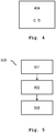
- Fig. 1 a block diagram of a method 100 of measuring elongation of a fastener with ultrasound is shown.
- the method is performed by a power tool comprising an ultrasonic transducer in acoustic contact with the fastener.
- the ultrasonic transducer is arranged such that ultrasonic signals may be transmitted into the fastener, and reflected ultrasonic signals may be received by the transducer.
- Ultrasonic signals may be transmitted and received by one and the same ultrasonic transducer element, or by two or more separate ultrasonic transducer elements.
- a set of primary minimum peak side lobe (MPS) coded ultrasonic signals with different base frequencies are transmitted, 101, into the fastener.
- MPS codes are binary sequences with low autocorrelation sidelobe levels. As one case the MPS codes are selected as Barker codes. Barker codes are a special case of MPS codes, which have sidelobes lower than other MPS codes.
- a MPS (or Barker) coded ultrasonic signal selected periods of an ultrasonic signal to be modulated by a MPS (or Barker) code are phase shifted according to the code.
- the ultrasonic signal to be modulated may be a sine burst, to maintain phase information in the ultrasonic signal after coding.
- a sine burst having a length of 11 sine periods is phase modulated according to the Barker (length 11) scheme (+1 +1 +1 -1 -1 -1 +1 -1 +1 -1 +1 -1), where +1 indicates positive phase (i.e. no phase modulation) and -1 indicates a phase shift of 180 degrees.
- the 4 th , 5 th , 6 th , 8 th , 9 th and 11 th periods of the sine burst are phase shifted 180 degrees.
- the set of primary minimum peak side lobe (MPS) coded ultrasonic signals transmitted into the fastener have different base frequencies, i.e. different periods of the sine wave modulated by the code.
- the base frequencies of the set of primary minimum peak side lobe (MPS) coded ultrasonic signals may be selected to be in the range of 2-18 MHz.
- the transmitted signals are reflected in the fastener, and thereafter a corresponding set of reflected primary ultrasonic signals is received, 102, from the fastener by the ultrasonic transducer of the power tool.
- the time of flight of the ultrasonic signals indicates the length of the fastener.
- the reflected primary ultrasonic signal is received by the power tool before the next primary ultrasonic signal is transmitted into the fastener.
- Each reflected primary ultrasonic signal received by the power tool is cross-correlated 103 with the corresponding transmitted primary ultrasonic signal.
- a set of primary cross-correlated signals is obtained.
- Each cross-correlated signal relates to the similarity of the received reflected signal and the corresponding transmitted signal.
- the base frequency of an ultrasonic measurement signal, for performing measurements of the fastener may be determined 105.
- the MPS signal having the highest quality attribute of the set of transmitted primary signals may be selected to perform measurements on the fastener.
- the ultrasonic measurement signal may be set to a chirp signal.
- the ultrasonic measurement signal is transmitted 106 into the fastener, and a reflected ultrasonic measurement signal is received 107 from the fastener.
- the elongation of the fastener may be measured 108, as will be described further down with reference to Fig. 7 .
- the elongation is the relative length change of the fastener, i.e. of a fastener during a fastening process.
- Fig. 3 shows a method 300 of determining pulse length of a MPS coded signal for measuring a fastener.
- a set of secondary minimum peak side lobe (MPS) coded ultrasonic signals with different signal pulse lengths are transmitted 301 into the fastener.
- the pulse lengths correspond to the number of periods of the MPS codes that are being used in the method. If the codes are limited to Barker codes, the available sequence lengths are 2, 3, 4, 5, 6, 11 and 13 periods of the modulated signal. For a certain base frequency, the pulse length of the signal may be determined as a number of periods of the base frequency.
- the sequence length of the MPS code for coding the signal may thus be selected to correspond to the number of periods of the base frequency. As an example, for a base frequency of 11 MHz the Barker 11 code will contain 11 periods of the modulated signal, thus resulting in a pulse length of 1 ⁇ s.
- a corresponding set of reflected secondary ultrasonic signals is received 302 from the fastener.
- Each reflected secondary ultrasonic signal is cross-correlated 303 with the corresponding transmitted secondary ultrasonic signal, thus obtaining a set of secondary cross-correlated signals.
- a quality attribute of each signal of the set of transmitted secondary signals is determined 304, and the pulse length of the ultrasonic measurement signal is determined based on the quality attributes of the set of transmitted secondary signals.
- the quality attribute of each signal of the set of transmitted secondary signals may be based on a cross-correlation peak uniqueness C and/or a cross-correlation peak symmetry D of the transmitted secondary signals.
- the frequency range of the chirp may be determined by the method 500 shown in Fig. 5 .
- a set of primary ultrasonic chirp signals with different base frequencies is transmitted 501 into the fastener by the ultrasonic transducer of the power tool.
- a corresponding set of reflected ultrasonic chirp signals is received 502 from the fastener, and the frequency range of the measurement chirp signal is determined 505 as the frequency range comprising the base frequency of the primary chirp signal having the maximum amplitude of the reflected ultrasonic signals.
- the lower frequency limit and the higher frequency limit of the range are set to frequencies where the reflected ultrasonic signals have an amplitude above a predetermined threshold, e.g. at least 10 % of the maximum amplitude of the reflected ultrasonic signals.
- the chirp signal may be configured to have a time dependent frequency curve with a rate of change of frequency that reflects a frequency response curve of the set of primary ultrasonic chirp signals, preferably such that the rate of change is the inverse to the frequency response curve of the set of primary ultrasonic chirp signals.
- a method 600 of measuring elongation of a fastener with ultrasound, performed by a power tool in acoustic contact with the fastener is shown.
- a minimum peak side lobe (MPS) coded ultrasonic measurement signal is transmitted 606 into the fastener by the ultrasonic transducer of the power tool.
- the measurement signal is reflected in the fastener, and a reflected ultrasonic measurement signal is received 607 from the fastener, by the power tool.
- the elongation of the fastener is thereafter measured 608.
- the method may be repeated 609 to monitor changes in elongation of the fastener.
- Changes in the elongation of the fastener may be measured 700 by continuously or periodically performing measurements as above and cross-correlating 710 the reflected ultrasonic measurement signal with the transmitted ultrasonic measurement signal. Phase information may thereafter be extracted 711 from the reflected measurement signal, and the elongation of the fastener may be determined 712 based on the extracted phase information.
- the method may comprise using the cross-correlated measurement signal to identify periods of the reflected signal being in phase with the modulated sine signal, and extracting phase information from the periods of the reflected signal being in phase.
- the periods of the reflected signal being in phase may be identified by masking the signal with the minimum peak side lobe (MPS) sequence of the transmitted measurement signal.
- MPS minimum peak side lobe
- the signal is then split into an I- and Q-channel and each channel is multiplied with a reference signal.
- the reference signal of the I-channel is a signal that has the same frequency and that is phase locked to the transmitted signal.
- the reference signal of the Q-channel corresponds to the I-channel reference signal, but phase shifted 90°.
- the I- and Q-channels are orthogonal to each other.
- the I- and Q-channels are thereafter low pass filtered to generate low pass filtered I- and Q-outputs. From these outputs the phase of the received signal may be extracted by calculating the arc tangent of the I- and Q-output signals.
- the elongation of a fastener drawn by the power tool may be monitored. For as long as the fastener is not subject to any elongation, e.g. prior to a fastening process having actually started, this phase difference between the transmitted and reflected signals will remain constant at some value.
- phase difference between the transmitted and reflected signals may be determined by the power tool. If the total phase difference exceeds a full period, the total number of periods that the echo signal undergoes during a fastening process may be counted. When the phase difference has reached a value corresponding to a desired fastener elongation, which in turn corresponds to a desired tightening force, the tightening process may be interrupted.
- the measurement should preferably be repeated at such high repetition frequency (e.g. 1 kHz or higher) during fastening that the phase difference of the reflected signal may be unambiguously determined between successive measurements.
- high repetition frequency e.g. 1 kHz or higher
- a power tool 800 is shown in the form of an assembly tool.
- the tool has a tool body 801 to be held by an operator, and a tool head 802 comprising a tool bit 803 for engagement with a fastener in the form of a fastener 804 (e.g. a screw or a nut).
- a fastener 804 e.g. a screw or a nut.
- the tool head further supports an ultrasonic transducer unit 805, such that it is in acoustic contact with the fastener.
- the ultrasonic transducer unit is arranged for transmitting ultrasonic signals into the fastener and receiving reflected ultrasonic signals from the fastener.
- the tool further comprises a processing unit 806 connected to the ultrasonic transducer unit by electrical connecting means 807.
- the tool and the processing unit is configured to perform the method as previously described by transmitting a set of primary minimum peak side lobe (MPS) coded ultrasonic signals with different base frequencies into the fastener, receiving a corresponding set of reflected primary ultrasonic signals from the fastener, cross-correlating each reflected primary ultrasonic signal with the corresponding transmitted primary ultrasonic signal, thus obtaining a set of cross-correlated signals, determining a quality attribute of each signal of the set of cross-correlated signals, determining at least one parameter of an ultrasonic measurement signal, for performing measurements of the fastener, based on the quality attributes of the set of cross-correlated signals, transmitting the ultrasonic measurement signal into the fastener, and receiving a reflected ultrasonic measurement signal from the fastener.
- MPS primary minimum peak side lobe
- the processing unit may be configured to perform the method as described by means of a computer program, which when executed by the processing unit performs the steps of the method.
- the power tool 800 and the processing unit 806 is configured to transmitting a minimum peak side lobe (MPS) coded ultrasonic measurement signal into the fastener, receiving a reflected ultrasonic measurement signal from the fastener, and measuring the elongation of the fastener based on the reflected ultrasonic measurement signal.
- MPS minimum peak side lobe
- the power tool may be adapted to perform any of the steps of the method as disclosed herein.
- the different steps of the method described above may be combined or performed in any suitable order.
- the method may be implemented by a computer program, having code means, which when run in a processing unit causes the processing unit to execute the steps of the method.
- the computer program may be comprised in a computer readable medium of a computer program product.
- the computer readable medium may consist of essentially any memory, such as a ROM (Read-Only Memory), a PROM (Programmable Read-Only Memory), an EPROM (Erasable PROM), a Flash memory, an EEPROM (Electrically Erasable PROM), or a hard disk drive.
Landscapes
- Physics & Mathematics (AREA)
- Acoustics & Sound (AREA)
- General Physics & Mathematics (AREA)
- Engineering & Computer Science (AREA)
- Mechanical Engineering (AREA)
- Investigating Or Analyzing Materials By The Use Of Ultrasonic Waves (AREA)
- Length Measuring Devices Characterised By Use Of Acoustic Means (AREA)
Description
- The invention relates to a method of measuring elongation of a fastener with ultrasound, performed by a power tool in acoustic contact with the fastener. The invention further relates to a power tool comprising a tool head for engaging with a fastener, an ultrasonic transducer unit for transmitting ultrasonic signals into the fastener and receiving reflected ultrasonic signals from the fastener.
- Power tools may be used in various assembly processes, including fastening of joints etc. When fastening joints it is important that fasteners of such joints are tightened such that required tightening force levels are reached.
- In order to control the tightening force of joints, the elongation of the fastener may be monitored during fastening. A previous patent
SE 533385 - However, there is always a need for improving such methods of measuring fasteners with ultrasound to be able to improve reliability and robustness of the measurements on elongation and thereby the reliability and robustness of measurements of the tightening force.
- An object of the invention is thus to provide improvements in measuring elongation of a fastener with ultrasound using a power tool. Particularly it is an object to improve the reliability and robustness of the measurements on elongation.
- Hence, the invention relates to a method of measuring elongation of a fastener with ultrasound, performed by a power tool in acoustic contact with the fastener. The method comprises:
- transmitting a set of primary minimum peak side lobe (MPS) coded ultrasonic signals with different base frequencies into the fastener,
- receiving a corresponding set of reflected primary ultrasonic signals from the fastener,
- cross-correlating each reflected primary ultrasonic signal with the corresponding transmitted primary ultrasonic signal, thus obtaining a set of primary cross-correlated signals,
- determining a quality attribute of each transmitted primary signal from the set of primary cross-correlated signals,
- determining at least one parameter of an ultrasonic measurement signal, for performing measurements of the fastener, based on the quality attributes of the set of transmitted primary signals,
- transmitting the ultrasonic measurement signal into the fastener, and
- receiving a reflected ultrasonic measurement signal from the fastener.
- By transmitting minimum peak side lobe (MPS) coded ultrasonic signals into the fastener and cross-correlating reflected and transmitted ultrasonic signals, a much better correlation may be achieved as compared to other types of signals, e.g. conventional sine bursts. The correlation between the reflected and transmitted ultrasonic signals may be used to track a phase change of the ultrasonic signal during elongation, e.g. tightening of a threaded fastener. By improving the correlation, a measurement of the phase change, and thus the elongation, may be made more reliable and robust. Thus the use of minimum peak side lobe (MPS) coded ultrasonic signals may result in a more reliable and robust measurement of elongation of a fastener. The measurement of elongation of a fastener with a power tool may therefore be improved.
- To obtain a MPS coded ultrasonic signal, selected periods of an ultrasonic signal to be modulated by a MPS code are phase shifted according to the MPS code.
- MPS codes are binary sequences with low autocorrelation sidelobe levels which have been identified with sequence lengths (periods of the modulated wave form) up to 48 (M.N. Cohen, M.R. Fox, J.M. Baden. Minimum peak sidelobes pulse compression codes, Proceedings of the IEEE International Radar Conference, Arlington, VA, May 1990, pp.633-638), and more recently up to 68 (Binary sequences with minimum peak sidelobe level up to length 68, A.N. Leukhin, E.N. Potehin, http://arxiv.org/ftp/arxiv/papers/1212/1212.4930.pdf).
- By transmitting a set of primary minimum peak side lobe (MPS) coded ultrasonic signals with different base frequencies into the fastener, cross-correlating each reflected primary ultrasonic signal with the corresponding transmitted primary ultrasonic signal and determining a quality attribute of each signal of the set of transmitted primary signals using the cross-correlated signals, at least one parameter of the ultrasonic measurement signal may be selected such that the actual measurement may be made more reliable and robust. The at least one parameter may comprise the type of ultrasonic measurement signal or any other parameter of the ultrasonic measurement signal.
- The MPS coded ultrasonic signals may be MPS coded ultrasonic sine signals. The ultrasonic signal modulated by the code may thus be a sinus signal or a sine burst. Thus phase information in the coded signal may be maintained.
- The quality attribute of each signal of the set of transmitted primary signals may be based on attributes selected from the group consisting the following attributes, or combinations thereof:
- An amplitude of the cross-correlated signal. This relates to the total amplitude of the signal. Thus the total amplitude of the signal may be used as a quality attribute, to enhance the signal-to-noise ratio.
- A cross-correlation peak height. This relates to the peak height of the most prominent peak, i.e. a main peak, in the cross-correlated signal. Thus the absolute peak height of the_most prominent correlation peak may be used as a quality attribute, to enhance the signal-to-noise ratio.
- A cross-correlation peak uniqueness. Different signal routes in the fastener may result in different time of flight of the signal and thus several correlation peaks. The cross-correlation peak uniqueness may relate to a ratio of peak height of a main peak to peak height of a secondary peak, e.g. the second most prominent peak in the cross-correlated signal. Thus the uniqueness of the most prominent peak with regard to other correlation peaks may be used as a quality attribute.
- A cross-correlation peak symmetry. This may relate to any measurement of symmetry of the main peak of the cross-correlated signal, e.g. symmetry of the left hand edge and the right hand edge. Overlapping correlation peaks corresponding to different signal routes in the fastener may result in asymmetric correlation peaks. By considering cross-correlation peak symmetry the risk of identifying overlapping correlation peaks etc. may be reduced.
- An I/Q signal variance. Thus the method may include an assessment of the quality of a phase extraction from the received signal. If the variation (variance) of the I/Q signal in a given interval is low, the quality of the extracted phase in this interval is high, indicating that the quality of the received signal is high in the interval.
- A difference between reflected signal phase and correlation peak position. The position of the correlation peak may be seen to indicate the time of flight of the signal in a number of periods of the base frequency of the signal. Any deviation from a complete number of periods, i.e. in parts of a period, may indicate a phase shift of the signal. This phase shift may be compared to the reflected signal phase to assess the quality of the signal.
- The quality attribute may be based on a weighted sum of a plurality of attributes of the set of transmitted primary signals, selected from the group consisting of an amplitude of the cross-correlated signal, a cross-correlation peak height, a cross-correlation peak uniqueness, a cross-correlation peak symmetry, an I/Q signal variance, a difference between reflected signal phase and correlation peak position.
- Thus a combined assessment of the plurality of attributes may be used as a basis for selecting the at least one parameter of the ultrasonic measurement signal.
- The ultrasonic measurement signal may be set to a minimum peak side lobe (MPS) coded ultrasonic signal if the quality attributes of at least one signal of the set of cross-correlated signals is above a predetermined value.
- Thus the ultrasonic measurement signal may be set to a minimum peak side lobe (MPS) coded ultrasonic signal when this type of signal is expected to result in a reliable and robust measurement of the elongation.
- The at least one parameter may comprise a measurement base frequency of the ultrasonic measurement signal. The measurement base frequency of the ultrasonic measurement signal may be set to the base frequency of the transmitted primary ultrasonic signal having the highest quality attribute of the set of transmitted primary signals.
- Thus the base frequency of the measurement signal may be set in relation to, or even corresponding to, the base frequency of the primary minimum peak side lobe (MPS) coded ultrasonic signal resulting in a high quality attribute.
- The method may further comprise:
- transmitting a set of secondary minimum peak side lobe (MPS) coded ultrasonic signals with different signal pulse lengths into the fastener,
- receiving a corresponding set of reflected secondary ultrasonic signals from the fastener, and
- cross-correlating each reflected secondary ultrasonic signal with the corresponding transmitted secondary ultrasonic signal, thus obtaining a set of secondary cross-correlated signals,
- determining a quality attribute of each signal of the set of transmitted secondary signals,
- determining the pulse length of the ultrasonic measurement signal based on the quality attributes of the set of transmitted secondary signals.
- For a certain base frequency, the pulse length of the signal may be determined as a number of periods of the base frequency. The sequence length of the MPS code for coding the signal may thus be selected to correspond to the number of periods of the base frequency.
- As previously noted, MPS codes are currently available in sequence lengths (periods of the modulated wave form) up to 68. Barker codes (a type of MPS codes) are known up to sequence lengths of 13. Thus the optimal pulse length of the signal, and the corresponding MPS code may be identified, for performing a measurement.
- The quality attribute of each signal of the set of transmitted secondary signals may be based on a cross-correlation peak uniqueness (C) and/or a cross-correlation peak symmetry (D) of the transmitted secondary signals.
- When determining a quality attribute of each signal for the selection of pulse length, the cross-correlation peak uniqueness (C) may relate to a ratio of peak height of a main peak to peak height of a secondary peak, e.g. the second most prominent peak in the cross-correlated signal. Thus the uniqueness of the most prominent peak with regard to other correlation peaks may be used as a quality attribute. The cross-correlation peak symmetry (D) may relate to any measurement of symmetry of the main peak, e.g. symmetry of the left hand edge and the right hand edge. Different signal routes in the fastener may result in different time of flight of the signal and thus several correlation peaks. Overlapping correlation peaks may result in asymmetric correlation peaks. By considering cross-correlation peak symmetry the risk of identifying overlapping correlation peaks etc. may be reduced.
- The ultrasonic measurement signal may be set to a chirp signal if the quality attributes of each of the set of transmitted primary signals are below a predetermined value.
- Thus if, based on the assessment of the quality attributes of the set of transmitted primary signals, no one of the MPS signals is expected to yield a reliable and robust measurement, the ultrasonic measurement signal may be set to a chirp signal. The chirp signal is also a low-autocorrelation signal.
- The frequency range of the chirp may be determined by:
- transmitting a set of primary ultrasonic chirp signals with different base frequencies into the fastener,
- receiving a corresponding set of reflected ultrasonic chirp signals from the fastener, and
- determining the frequency range of a measurement chirp signal to comprise the base frequency of the primary chirp signal having the maximum amplitude of the reflected ultrasonic signals.
- The frequency range of the chirp may further be determined by defining the range by a lower frequency limit and a higher frequency limit, comprising the base frequency of the primary chirp signal having the maximum amplitude of the reflected ultrasonic signals, and wherein the lower frequency limit and the higher frequency limit are set to frequencies where the reflected ultrasonic signals have an amplitude above a predetermined threshold, e.g. at least 10 % of the maximum amplitude of the reflected ultrasonic signals.
- Thus the measurement chirp signal may be selected to encompass the range of frequencies where the most reliable and robust measurement may be achieved.
- The chirp signal may have a time dependent frequency curve having a rate of change that reflects a frequency response curve of the set of primary ultrasonic chirp signals, defined as the amplitude of the reflected ultrasonic signals as a function of the frequency of the transmitted signals. The rate of change may preferably be inverse to the frequency response curve of the set of primary ultrasonic chirp signals.
- Thus the energy used in the chirp measurement signal may be optimised by adjusting the amplitude of individual frequency components in the chirp signal as a function of the amplitude of the reflected ultrasonic signals.
- The invention further relates to a method of measuring elongation of a fastener with ultrasound, performed by a power tool in acoustic contact with the fastener, comprising:
- transmitting a minimum peak side lobe (MPS) coded ultrasonic measurement signal into the fastener,
- receiving a reflected ultrasonic measurement signal from the fastener, and
- measuring the elongation of the fastener based on the reflected ultrasonic measurement signal.
- As previously noted, by transmitting minimum peak side lobe (MPS) coded ultrasonic signals into the fastener and cross-correlating reflected and transmitted ultrasonic signals, a much better correlation is achieved when compared to other types of signals, e.g. conventional sine bursts. The correlation between the reflected and transmitted ultrasonic signals may be used to track a phase change of the ultrasonic signal during elongation, e.g. tightening of a threaded fastener. By improving the correlation a measurement of the phase change may be made more reliable and robust. Thus the use of minimum peak side lobe (MPS) coded ultrasonic signals facilitates a more reliable and robust measurement of elongation of a fastener, and the measurement of elongation of a fastener with a power tool may be improved.
- The method may further comprise:
- cross-correlating the reflected ultrasonic measurement signal with the transmitted ultrasonic measurement signal, thus obtaining a cross-correlated measurement signal,
- extracting phase information from the reflected measurement signal, and
- determining the elongation of the fastener based on the extracted phase information.
- The step of extracting phase information from the reflected measurement signal may comprise using the cross-correlated measurement signal to identify periods of the reflected signal being in phase, and extracting phase information from the periods of the reflected signal being in phase.
- The periods of the reflected signal being in phase may be identified by masking the signal with the minimum peak side lobe (MPS) sequence of the transmitted measurement signal.
- The step of extracting phase information from the reflected measurement signal may comprise I/Q-modulating the reflected signal and extracting the phase information.
- The minimum peak side lobe (MPS) coded ultrasonic signal(s) may be (a) Barker coded or quasi Barker coded ultrasonic signal(s).
- Barker coded signals are signals coded according to a Barker sequence. Barker codes are a special case of a minimum peak side lobe (MPS) codes. Barker codes are known for sequences up to 13 periods and have a maximum autocorrelation sequence which has sidelobes lower than a predetermined threshold.
Length Known Barker codes 2 +1 -1 +1 +1 3 +1 +1 -1 4 +1 +1 -1 +1 +1 +1 +1 -1 5 +1 +1 +1 -1 +1 7 +1 +1 +1 -1 -1 +1 -1 11 +1 +1 +1 -1 -1 -1 +1 -1 -1 +1 -1 13 +1 +1 +1 +1 +1 -1 -1 +1 +1 -1 +1 -1 +1 - The positive and negative amplitudes (+1 and -1) of the Barker codes imply a biphase modulation, i.e. the change of phase in the carrier wave making up the Barker code is 180 degrees.
- Alternatively, the change of phase in the carrier wave may be less than 180 degrees, e.g. 90 degrees, defining a quasi-Barker code.
- The modulated waveform may be a sine wave, e.g. a sine burst, thus maintaining phase information in the coded signal. The MPS or Barker coded signal may thus be a sine burst with square envelope, where selected periods of the sine burst are phase shifted according to the MPS or Barker coded carrier wave.
- The method may be performed by a power fastening tool, wherein the fastener is a fastener tightened by the power fastening tool.
- Thereby, the method of performing a reliable and robust measurement of the elongation of the fastener may be used while tightening the fastener. The method may therefore be used to improve the repeatability in the degree of tightening, e.g. while tightening threaded fasteners.
- The invention further relates to a power tool comprising a tool head for engaging with a fastener, an ultrasonic transducer unit for transmitting ultrasonic signals into the fastener and receiving reflected ultrasonic signals from the fastener, and a processing unit connected to the ultrasonic transducer unit,
wherein the power tool is configured to: - transmitting a set of primary minimum peak side lobe (MPS) coded ultrasonic signals with different base frequencies into the fastener,
- receiving a corresponding set of reflected primary ultrasonic signals from the fastener,
- cross-correlating each reflected primary ultrasonic signal with the corresponding transmitted primary ultrasonic signal, thus obtaining a set of primary cross-correlated signals,
- determining a quality attribute of each signal of the set of transmitted primary signals,
- determining at least one parameter of an ultrasonic measurement signal, for performing measurements of the fastener, based on the quality attributes of the set of transmitted primary signals,
- transmitting the ultrasonic measurement signal into the fastener, and
- receiving a reflected ultrasonic measurement signal from the fastener.
- Thus the advantages of the method disclosed herein may be achieved by the power tool, obtaining good correlation between transmitted and reflected signals by using minimum peak side lobe (MPS) coded ultrasonic signals, and facilitating a more reliable and robust measurement of elongation of the fastener engaged by the tool head.
- The power tool may further configured to perform the method as further disclosed herein, to achieve the advantages disclosed.
- The invention further relates to a power tool comprising a tool head for engaging with a fastener, an ultrasonic transducer unit for transmitting ultrasonic signals into the fastener and receiving reflected ultrasonic signals from the fastener, and a processing unit connected to the ultrasonic transducer unit,
wherein the power tool is configured to: - transmitting a minimum peak side lobe (MPS) coded ultrasonic measurement signal into the fastener,
- receiving a reflected ultrasonic measurement signal from the fastener, and
- measuring the elongation of the fastener based on the reflected ultrasonic measurement signal.
- Thus the advantages of the method disclosed herein may be achieved by the power tool, obtaining good correlation between transmitted and reflected signals by using minimum peak side lobe (MPS) coded ultrasonic signals, and facilitating a more reliable and robust measurement of elongation of the fastener engaged by the tool head.
- The power tool may further be configured to:
- cross-correlating the reflected ultrasonic measurement signal with the transmitted ultrasonic measurement signal, thus obtaining a cross-correlated measurement signal,
- extracting phase information from the reflected measurement signal and/or from the cross-correlated measurement signal, and
- determining the elongation of the fastener based on the phase information.
- The power tool may be a power fastening tool, and the fastener may be a fastener tightened by the power fastening tool.
- The minimum peak side lobe (MPS) coded ultrasonic signal(s) may be (a) barker coded or quasi barker coded ultrasonic signal(s).
- Other features and advantages of the invention will be apparent from the figures and from the detailed description of the shown embodiment.
- In the following detailed description reference is made to the accompanying drawings, of which:
-
Fig. 1 shows a block diagram of a method of measuring elongation of a fastener with ultrasound, according to one embodiment. -
Fig. 2 shows a block diagram of part of a method of measuring elongation of a fastener with ultrasound, according to another embodiment. -
Fig. 3 shows a block diagram of a method of measuring elongation of a fastener with ultrasound, according to yet another embodiment. -
Fig. 4 shows a block diagram of part of a method of measuring elongation of a fastener with ultrasound, according to yet another embodiment. -
Fig. 5 shows a block diagram of part of a method of measuring elongation of a fastener with ultrasound, according to a further embodiment. -
Fig. 6 shows a block diagram of a method of measuring elongation of a fastener with ultrasound, according to yet a further embodiment. -
Fig. 7 shows a block diagram of a method of measuring elongation of a fastener with ultrasound, according to still another embodiment. -
Fig. 8 shows a power tool according to an embodiment. - In
Fig. 1 a block diagram of amethod 100 of measuring elongation of a fastener with ultrasound is shown. The method is performed by a power tool comprising an ultrasonic transducer in acoustic contact with the fastener. The ultrasonic transducer is arranged such that ultrasonic signals may be transmitted into the fastener, and reflected ultrasonic signals may be received by the transducer. Ultrasonic signals may be transmitted and received by one and the same ultrasonic transducer element, or by two or more separate ultrasonic transducer elements. A set of primary minimum peak side lobe (MPS) coded ultrasonic signals with different base frequencies are transmitted, 101, into the fastener. MPS codes are binary sequences with low autocorrelation sidelobe levels. As one case the MPS codes are selected as Barker codes. Barker codes are a special case of MPS codes, which have sidelobes lower than other MPS codes. - To obtain a MPS (or Barker) coded ultrasonic signal, selected periods of an ultrasonic signal to be modulated by a MPS (or Barker) code are phase shifted according to the code. The ultrasonic signal to be modulated may be a sine burst, to maintain phase information in the ultrasonic signal after coding.
- As one example, to obtain a Barker coded ultrasonic signal corresponding to a Barker code of length 11, a sine burst having a length of 11 sine periods is phase modulated according to the Barker (length 11) scheme (+1 +1 +1 -1 -1 -1 +1 -1 -1 +1 -1), where +1 indicates positive phase (i.e. no phase modulation) and -1 indicates a phase shift of 180 degrees. Thus the 4th, 5th, 6th, 8th, 9th and 11th periods of the sine burst are phase shifted 180 degrees.
- The set of primary minimum peak side lobe (MPS) coded ultrasonic signals transmitted into the fastener have different base frequencies, i.e. different periods of the sine wave modulated by the code. The base frequencies of the set of primary minimum peak side lobe (MPS) coded ultrasonic signals may be selected to be in the range of 2-18 MHz.
- The transmitted signals are reflected in the fastener, and thereafter a corresponding set of reflected primary ultrasonic signals is received, 102, from the fastener by the ultrasonic transducer of the power tool. The time of flight of the ultrasonic signals indicates the length of the fastener. Typically, the reflected primary ultrasonic signal is received by the power tool before the next primary ultrasonic signal is transmitted into the fastener.
- Each reflected primary ultrasonic signal received by the power tool is cross-correlated 103 with the corresponding transmitted primary ultrasonic signal. Thus a set of primary cross-correlated signals is obtained. Each cross-correlated signal relates to the similarity of the received reflected signal and the corresponding transmitted signal.
- From the set of primary cross-correlated signals, a quality attribute is determined 104 for each of the transmitted primary signals. With reference to
Fig. 2 , the quality attribute of each signal of the set of transmitted primary signals may be based on a weighted sum of attributes selected from A, B, C, D, E and F in the following group: - An amplitude A of the cross-correlated signal. This relates to the total amplitude of the signal. Thus the total amplitude of the signal may be used as a quality attribute, to enhance the signal-to-noise ratio.
- A cross-correlation peak height B. This relates to the peak height of the most prominent peak, i.e. a main peak, in the cross-correlated signal. Thus the absolute peak height of the most prominent correlation peak may be used as a quality attribute, to enhance the signal-to-noise ratio.
- A cross-correlation peak uniqueness C. Different signal routes in the fastener may result in different time of flight of the signal and thus several correlation peaks. The cross-correlation peak uniqueness may relate to a ratio of peak height of a main peak to peak height of a secondary peak, e.g. the second most prominent peak in the cross-correlated signal. Thus the uniqueness of the most prominent peak with regard to other correlation peaks may be used as a quality attribute.
- A cross-correlation peak symmetry D. This may relate to any measurement of symmetry of the main peak of the cross-correlated signal, e.g. symmetry of the left hand edge and the right hand edge. Overlapping correlation peaks corresponding to different signal routes in the fastener may result in asymmetric correlation peaks. By considering cross-correlation peak symmetry the risk of identifying overlapping correlation peaks etc. may be reduced.
- An I/Q signal variance E. Thus the method may include an assessment of the quality of a phase extraction from the received signal. If the variation (variance) of the I/Q signal in a given interval is low, the quality of the extracted phase in this interval is high, indicating that the quality of the received signal is high in the interval.
- A difference F between reflected signal phase and correlation peak position. The position of the correlation peak may be seen to indicate the time of flight of the signal in a number of periods of the base frequency of the signal. Any deviation from a complete number of periods, i.e. in parts of a period, may indicate a phase shift of the signal. This phase shift may be compared to the reflected signal phase to assess the quality of the signal.
- Based on the quality attributes of the set of transmitted primary signals, the base frequency of an ultrasonic measurement signal, for performing measurements of the fastener, may be determined 105. Thus the MPS signal having the highest quality attribute of the set of transmitted primary signals may be selected to perform measurements on the fastener.
- Alternatively, if the quality attributes of each of the set of transmitted primary signals are below a predetermined value, the ultrasonic measurement signal may be set to a chirp signal.
- Thereafter, the ultrasonic measurement signal is transmitted 106 into the fastener, and a reflected ultrasonic measurement signal is received 107 from the fastener. Based on the transmitted and reflected measurement signal, the elongation of the fastener may be measured 108, as will be described further down with reference to
Fig. 7 . The elongation is the relative length change of the fastener, i.e. of a fastener during a fastening process. - Further to what is described above,
Fig. 3 shows amethod 300 of determining pulse length of a MPS coded signal for measuring a fastener. A set of secondary minimum peak side lobe (MPS) coded ultrasonic signals with different signal pulse lengths are transmitted 301 into the fastener. The pulse lengths correspond to the number of periods of the MPS codes that are being used in the method. If the codes are limited to Barker codes, the available sequence lengths are 2, 3, 4, 5, 6, 11 and 13 periods of the modulated signal. For a certain base frequency, the pulse length of the signal may be determined as a number of periods of the base frequency. The sequence length of the MPS code for coding the signal may thus be selected to correspond to the number of periods of the base frequency. As an example, for a base frequency of 11 MHz the Barker 11 code will contain 11 periods of the modulated signal, thus resulting in a pulse length of 1 µs. - A corresponding set of reflected secondary ultrasonic signals is received 302 from the fastener. Each reflected secondary ultrasonic signal is cross-correlated 303 with the corresponding transmitted secondary ultrasonic signal, thus obtaining a set of secondary cross-correlated signals. A quality attribute of each signal of the set of transmitted secondary signals is determined 304, and the pulse length of the ultrasonic measurement signal is determined based on the quality attributes of the set of transmitted secondary signals. As illustrated in
Fig. 4 , the quality attribute of each signal of the set of transmitted secondary signals may be based on a cross-correlation peak uniqueness C and/or a cross-correlation peak symmetry D of the transmitted secondary signals. - If the measurement signal is selected to a ultrasonic chirp signal in the
previous step 105 shown inFig. 1 , the frequency range of the chirp may be determined by themethod 500 shown inFig. 5 . A set of primary ultrasonic chirp signals with different base frequencies is transmitted 501 into the fastener by the ultrasonic transducer of the power tool. A corresponding set of reflected ultrasonic chirp signals is received 502 from the fastener, and the frequency range of the measurement chirp signal is determined 505 as the frequency range comprising the base frequency of the primary chirp signal having the maximum amplitude of the reflected ultrasonic signals. The lower frequency limit and the higher frequency limit of the range are set to frequencies where the reflected ultrasonic signals have an amplitude above a predetermined threshold, e.g. at least 10 % of the maximum amplitude of the reflected ultrasonic signals. The chirp signal may be configured to have a time dependent frequency curve with a rate of change of frequency that reflects a frequency response curve of the set of primary ultrasonic chirp signals, preferably such that the rate of change is the inverse to the frequency response curve of the set of primary ultrasonic chirp signals. - In
Fig. 6 , a method 600 of measuring elongation of a fastener with ultrasound, performed by a power tool in acoustic contact with the fastener, is shown. A minimum peak side lobe (MPS) coded ultrasonic measurement signal is transmitted 606 into the fastener by the ultrasonic transducer of the power tool. The measurement signal is reflected in the fastener, and a reflected ultrasonic measurement signal is received 607 from the fastener, by the power tool. Based on the reflected ultrasonic measurement signal, the elongation of the fastener is thereafter measured 608. The method may be repeated 609 to monitor changes in elongation of the fastener. - Changes in the elongation of the fastener may be measured 700 by continuously or periodically performing measurements as above and cross-correlating 710 the reflected ultrasonic measurement signal with the transmitted ultrasonic measurement signal. Phase information may thereafter be extracted 711 from the reflected measurement signal, and the elongation of the fastener may be determined 712 based on the extracted phase information.
- To extract phase information from the reflected measurement signal of a MPS signal, the method may comprise using the cross-correlated measurement signal to identify periods of the reflected signal being in phase with the modulated sine signal, and extracting phase information from the periods of the reflected signal being in phase. The periods of the reflected signal being in phase may be identified by masking the signal with the minimum peak side lobe (MPS) sequence of the transmitted measurement signal.
- Phase information may be extracted from the received signal by means of I/Q-modulation (I = in-phase, Q = quadrature), also known as quadrature amplitude modulation.
- The signal is then split into an I- and Q-channel and each channel is multiplied with a reference signal. The reference signal of the I-channel is a signal that has the same frequency and that is phase locked to the transmitted signal. The reference signal of the Q-channel corresponds to the I-channel reference signal, but phase shifted 90°. The I- and Q-channels are orthogonal to each other.
- The I- and Q-channels are thereafter low pass filtered to generate low pass filtered I- and Q-outputs. From these outputs the phase of the received signal may be extracted by calculating the arc tangent of the I- and Q-output signals.
- By the method disclosed the elongation of a fastener drawn by the power tool may be monitored. For as long as the fastener is not subject to any elongation, e.g. prior to a fastening process having actually started, this phase difference between the transmitted and reflected signals will remain constant at some value.
- When the fastening process commences this phase difference will increase due to the fact that the elongation of the fastener will result in a longer time of flight of the ultrasonic signal in the fastener. The increasing tension in the fastener also results in a lower speed of sound, thus further increasing the time of flight. By continuously performing measurements as described above, the phase difference between the transmitted and reflected signals may be determined by the power tool. If the total phase difference exceeds a full period, the total number of periods that the echo signal undergoes during a fastening process may be counted. When the phase difference has reached a value corresponding to a desired fastener elongation, which in turn corresponds to a desired tightening force, the tightening process may be interrupted.
- The measurement should preferably be repeated at such high repetition frequency (e.g. 1 kHz or higher) during fastening that the phase difference of the reflected signal may be unambiguously determined between successive measurements.
- In
Fig. 8 , apower tool 800 is shown in the form of an assembly tool. The tool has atool body 801 to be held by an operator, and atool head 802 comprising atool bit 803 for engagement with a fastener in the form of a fastener 804 (e.g. a screw or a nut). During the process of fastening, the tool head and the tool bit is driven in rotation to rotate the fastener. The tool head further supports anultrasonic transducer unit 805, such that it is in acoustic contact with the fastener. One example of a construction of such an ultrasonic transducer unit arrangement is disclosed inSE 533385 processing unit 806 connected to the ultrasonic transducer unit by electrical connectingmeans 807. - The tool and the processing unit is configured to perform the method as previously described by transmitting a set of primary minimum peak side lobe (MPS) coded ultrasonic signals with different base frequencies into the fastener, receiving a corresponding set of reflected primary ultrasonic signals from the fastener, cross-correlating each reflected primary ultrasonic signal with the corresponding transmitted primary ultrasonic signal, thus obtaining a set of cross-correlated signals, determining a quality attribute of each signal of the set of cross-correlated signals, determining at least one parameter of an ultrasonic measurement signal, for performing measurements of the fastener, based on the quality attributes of the set of cross-correlated signals, transmitting the ultrasonic measurement signal into the fastener, and receiving a reflected ultrasonic measurement signal from the fastener.
- The processing unit may be configured to perform the method as described by means of a computer program, which when executed by the processing unit performs the steps of the method.
- According to one embodiment the
power tool 800 and theprocessing unit 806 is configured to transmitting a minimum peak side lobe (MPS) coded ultrasonic measurement signal into the fastener, receiving a reflected ultrasonic measurement signal from the fastener, and measuring the elongation of the fastener based on the reflected ultrasonic measurement signal. - The power tool may be adapted to perform any of the steps of the method as disclosed herein. The different steps of the method described above may be combined or performed in any suitable order.
- The method may be implemented by a computer program, having code means, which when run in a processing unit causes the processing unit to execute the steps of the method. The computer program may be comprised in a computer readable medium of a computer program product. The computer readable medium may consist of essentially any memory, such as a ROM (Read-Only Memory), a PROM (Programmable Read-Only Memory), an EPROM (Erasable PROM), a Flash memory, an EEPROM (Electrically Erasable PROM), or a hard disk drive.
- The power tool and the methods disclosed herein may be modified by those skilled in the art, as compared to the exemplary embodiments described above.
- As is obvious for a skilled person, a number of other implementations, modifications, variations and/or additions can be made to the above described exemplary embodiments. It is to be understood that the invention includes all such other implementations, modifications, variations and/or additions which fall within the scope of the claims.
Claims (15)
- A method (100) of measuring elongation of a fastener with ultrasound, performed by a power tool in acoustic contact with the fastener, comprising:- transmitting (101) a set of primary minimum peak side lobe (MPS) coded ultrasonic signals with different base frequencies into the fastener,- receiving (102) a corresponding set of reflected primary ultrasonic signals from the fastener,- cross-correlating (103) each reflected primary ultrasonic signal with the corresponding transmitted primary ultrasonic signal, thus obtaining a set of primary cross-correlated signals,- determining (104) a quality attribute of each transmitted primary signal from the set of primary cross-correlated signals,- determining (105) at least one parameter of an ultrasonic measurement signal, for performing measurements of the fastener, based on the quality attributes of the set of transmitted primary signals,- transmitting (106) the ultrasonic measurement signal into the fastener,- receiving (107) a reflected ultrasonic measurement signal from the fastener, and- measuring (108) the elongation of the fastener based on the reflected ultrasonic measurement signal.
- The method according to claim 1 wherein the quality attribute (104, 204) of each signal of the set of transmitted primary signals is based on attributes selected from the group consisting of an amplitude (A) of the cross-correlated signal, a cross-correlation peak height (B), a cross-correlation peak uniqueness (C), a cross-correlation peak symmetry (D), an I/Q signal variance (E), a difference between reflected signal phase and correlation peak position (F), or combinations thereof.
- The method according to claim 2 wherein the quality attribute (104, 204) is based on a weighted sum of a plurality of attributes of the respective transmitted primary signals selected from the group consisting of an amplitude (A) of the cross-correlated signal, a cross-correlation peak height (B), a cross-correlation peak uniqueness (C), a cross-correlation peak symmetry (D), an I/Q signal variance (E), a difference between reflected signal phase and correlation peak position (F).
- The method according to any one of the preceding claims wherein the ultrasonic measurement signal is set to a minimum peak side lobe (MPS) coded ultrasonic signal if the quality attributes of at least one signal of the set of transmitted primary signals is above a predetermined value.
- The method according to claim 4 wherein the at least one parameter comprises a measurement base frequency of the ultrasonic measurement signal.
- The method according to claim 5 wherein the measurement base frequency of the ultrasonic measurement signal is set to the base frequency of the primary ultrasonic signal having the highest quality attribute of the set of transmitted primary signals.
- The method (100, 300) according to any one of claims 4-6 further comprising:- transmitting (301) a set of secondary minimum peak side lobe (MPS) coded ultrasonic signals with different signal pulse lengths into the fastener,- receiving (302) a corresponding set of reflected secondary ultrasonic signals from the fastener, and- cross-correlating (303) each reflected secondary ultrasonic signal with the corresponding transmitted secondary ultrasonic signal, thus obtaining a set of secondary cross-correlated signals,- determining (304) a quality attribute of each signal of the set of transmitted secondary signals from the set of cross-correlated signals,- determining (305) the pulse length of the ultrasonic measurement signal based on the quality attributes of the set of transmitted secondary signals.
- The method according to claim 7, wherein the quality attribute (304, 404) of each signal of the set of transmitted secondary signals is based on a cross-correlation peak uniqueness (C) and/or a cross-correlation peak symmetry (D) of the secondary cross-correlated signals.
- The method (100) according to any one of claims 1-3 wherein the ultrasonic measurement signal is set to a chirp signal if the quality attributes of each of the set of transmitted primary signals are below a predetermined value.
- The method (100, 500) according to claim 9, wherein the frequency range of the chirp is determined by:- transmitting (501) a set of primary ultrasonic chirp signals with different base frequencies into the fastener,- receiving (502) a corresponding set of reflected ultrasonic chirp signals from the fastener, and- determining (505) the frequency range of a measurement chirp signal to comprise the base frequency of the primary chirp signal having the maximum amplitude of the reflected ultrasonic signals.
- The method according to claim 9 or 10, wherein the chirp signal have a time dependent frequency curve having a rate of change that reflects a frequency response curve of the set of primary ultrasonic chirp signals, preferably such that the rate of change is the inverse to the frequency response curve of the set of primary ultrasonic chirp signals.
- The method according to any one of the preceding claims wherein the minimum peak side lobe (MPS) coded ultrasonic signal(s) is/are (a) Barker coded or quasi Barker coded ultrasonic signal (s).
- The method according to any one of the preceding claims wherein the method is performed by a power fastening tool, and wherein the fastener is a fastener drawn by the power fastening tool.
- A power tool (800) comprising a tool head (802) configured for engaging with a fastener, an ultrasonic transducer unit (805) configured for transmitting ultrasonic signals into the fastener and receiving reflected ultrasonic signals from the fastener, and a processing unit (806) connected to the ultrasonic transducer unit,
wherein the power tool is configured to:- transmitting a set of primary minimum peak side lobe (MPS) coded ultrasonic signals with different base frequencies into the fastener,- receiving a corresponding set of reflected primary ultrasonic signals from the fastener,- cross-correlating each reflected primary ultrasonic signal with the corresponding transmitted primary ultrasonic signal, thus obtaining a set of cross-correlated signals,- determining a quality attribute of each signal of the set of cross-correlated signals,- determining at least one parameter of an ultrasonic measurement signal, for performing measurements of the fastener, based on the quality attributes of the set of cross-correlated signals,- transmitting the ultrasonic measurement signal into the fastener,- receiving a reflected ultrasonic measurement signal from the fastener, and- measuring the elongation of the fastener based on the reflected ultrasonic measurement signal. - The power tool according to claim 14, further configured to perform the method according to any one of claims 2-11.
Applications Claiming Priority (2)
| Application Number | Priority Date | Filing Date | Title |
|---|---|---|---|
| SE1350717 | 2013-06-12 | ||
| PCT/EP2014/061936 WO2014198680A1 (en) | 2013-06-12 | 2014-06-09 | A method of measuring elongation of a fastener with ultrasound, performed by a power tool, and a power tool |
Publications (2)
| Publication Number | Publication Date |
|---|---|
| EP3008439A1 EP3008439A1 (en) | 2016-04-20 |
| EP3008439B1 true EP3008439B1 (en) | 2017-08-09 |
Family
ID=50897635
Family Applications (1)
| Application Number | Title | Priority Date | Filing Date |
|---|---|---|---|
| EP14728981.3A Active EP3008439B1 (en) | 2013-06-12 | 2014-06-09 | A method of measuring elongation of a fastener with ultrasound, performed by a power tool, and a power tool |
Country Status (5)
| Country | Link |
|---|---|
| US (1) | US9625334B2 (en) |
| EP (1) | EP3008439B1 (en) |
| JP (1) | JP6505089B2 (en) |
| CN (1) | CN105324651B (en) |
| WO (1) | WO2014198680A1 (en) |
Families Citing this family (34)
| Publication number | Priority date | Publication date | Assignee | Title |
|---|---|---|---|---|
| GB2513884B (en) | 2013-05-08 | 2015-06-17 | Univ Bristol | Method and apparatus for producing an acoustic field |
| US9612658B2 (en) | 2014-01-07 | 2017-04-04 | Ultrahaptics Ip Ltd | Method and apparatus for providing tactile sensations |
| GB2530036A (en) | 2014-09-09 | 2016-03-16 | Ultrahaptics Ltd | Method and apparatus for modulating haptic feedback |
| EP3537265B1 (en) | 2015-02-20 | 2021-09-29 | Ultrahaptics Ip Ltd | Perceptions in a haptic system |
| KR102524966B1 (en) | 2015-02-20 | 2023-04-21 | 울트라햅틱스 아이피 엘티디 | Algorithm improvements in haptic systems |
| US10818162B2 (en) | 2015-07-16 | 2020-10-27 | Ultrahaptics Ip Ltd | Calibration techniques in haptic systems |
| US11189140B2 (en) | 2016-01-05 | 2021-11-30 | Ultrahaptics Ip Ltd | Calibration and detection techniques in haptic systems |
| US10268275B2 (en) | 2016-08-03 | 2019-04-23 | Ultrahaptics Ip Ltd | Three-dimensional perceptions in haptic systems |
| US10943578B2 (en) | 2016-12-13 | 2021-03-09 | Ultrahaptics Ip Ltd | Driving techniques for phased-array systems |
| US10914710B2 (en) * | 2017-04-03 | 2021-02-09 | Savant Technologies Llc | Ultrasonic bridge for wireless communication |
| US11531395B2 (en) | 2017-11-26 | 2022-12-20 | Ultrahaptics Ip Ltd | Haptic effects from focused acoustic fields |
| JP7483610B2 (en) | 2017-12-22 | 2024-05-15 | ウルトラハプティクス アイピー リミテッド | Minimizing unwanted responses in haptic systems |
| US11360546B2 (en) * | 2017-12-22 | 2022-06-14 | Ultrahaptics Ip Ltd | Tracking in haptic systems |
| AU2019264014A1 (en) | 2018-05-02 | 2020-12-03 | Ultrahaptics Ip Ltd | Blocking plate structure for improved acoustic transmission efficiency |
| US11098951B2 (en) | 2018-09-09 | 2021-08-24 | Ultrahaptics Ip Ltd | Ultrasonic-assisted liquid manipulation |
| US11378997B2 (en) | 2018-10-12 | 2022-07-05 | Ultrahaptics Ip Ltd | Variable phase and frequency pulse-width modulation technique |
| CN109489887A (en) * | 2018-12-13 | 2019-03-19 | 安徽江淮汽车集团股份有限公司 | Bolt elongate measures test system |
| WO2020126234A1 (en) * | 2018-12-19 | 2020-06-25 | Atlas Copco Industrial Technique Ab | A method, an electric tool and computer program for setting an operating mode and/or associate result values of an electric tool |
| WO2020141330A2 (en) | 2019-01-04 | 2020-07-09 | Ultrahaptics Ip Ltd | Mid-air haptic textures |
| US12373033B2 (en) | 2019-01-04 | 2025-07-29 | Ultrahaptics Ip Ltd | Mid-air haptic textures |
| US11842517B2 (en) | 2019-04-12 | 2023-12-12 | Ultrahaptics Ip Ltd | Using iterative 3D-model fitting for domain adaptation of a hand-pose-estimation neural network |
| DE102019212837A1 (en) * | 2019-08-27 | 2021-03-04 | Conti Temic Microelectronic Gmbh | ULTRASONIC SENSOR SYSTEM, METHOD OF OPERATING ULTRASONIC SENSORS AND MOTOR VEHICLE |
| US11374586B2 (en) | 2019-10-13 | 2022-06-28 | Ultraleap Limited | Reducing harmonic distortion by dithering |
| CN114631139A (en) | 2019-10-13 | 2022-06-14 | 超飞跃有限公司 | Dynamic capping with virtual microphones |
| WO2021090028A1 (en) | 2019-11-08 | 2021-05-14 | Ultraleap Limited | Tracking techniques in haptics systems |
| US11715453B2 (en) | 2019-12-25 | 2023-08-01 | Ultraleap Limited | Acoustic transducer structures |
| US11816267B2 (en) | 2020-06-23 | 2023-11-14 | Ultraleap Limited | Features of airborne ultrasonic fields |
| CN114185446B (en) * | 2020-09-15 | 2026-01-20 | 华为技术有限公司 | Calibration signal generation method, electronic equipment and computer storage medium |
| US11886639B2 (en) | 2020-09-17 | 2024-01-30 | Ultraleap Limited | Ultrahapticons |
| CN112684006B (en) * | 2020-12-09 | 2023-01-17 | 东莞理工学院 | Ultrasonic detection method and system for bolt damage based on OVSF code |
| US12517585B2 (en) | 2021-07-15 | 2026-01-06 | Ultraleap Limited | Control point manipulation techniques in haptic systems |
| US12688761B2 (en) | 2022-01-02 | 2026-07-21 | Sim Ip Hxr Llc | Mid-air haptic generation analytic techniques |
| SE546313C2 (en) * | 2022-09-14 | 2024-10-01 | Atlas Copco Ind Technique Ab | Machine learning method of facilitating applying a desired clamp force by a tightening tool |
| US12659636B2 (en) | 2022-10-11 | 2026-06-16 | Sim Ip Hxr Llc | Acoustic transducer mounts |
Family Cites Families (15)
| Publication number | Priority date | Publication date | Assignee | Title |
|---|---|---|---|---|
| US3856985A (en) * | 1973-05-17 | 1974-12-24 | Tokyo Shibaura Electric Co | Ultrasonic diagnostic apparatus |
| US4602511A (en) * | 1985-06-20 | 1986-07-29 | J. A. Green Company | Method for measuring fastener stress utilizing longitudinal and transverse ultrasonic wave time-of-flight |
| US4787252A (en) * | 1987-09-30 | 1988-11-29 | Panametrics, Inc. | Differential correlation analyzer |
| CN1031367C (en) * | 1991-10-14 | 1996-03-20 | 三菱电机株式会社 | Check device |
| JP3022108B2 (en) * | 1993-12-14 | 2000-03-15 | 日本鋼管株式会社 | Ultrasound transceiver |
| JPH09229788A (en) * | 1996-02-22 | 1997-09-05 | Toyota Motor Corp | Bolt axial force measuring device and measuring method |
| US5970798A (en) | 1997-09-25 | 1999-10-26 | The United States Of America As Represented By The Administrator Of The National Aeronautics And Space Administration | Ultrasonic bolt gage |
| JPH11309146A (en) * | 1998-03-26 | 1999-11-09 | General Electric Co <Ge> | System and method for imaging a stream of ultrasonic scatterers |
| US6415665B1 (en) * | 2000-03-13 | 2002-07-09 | General Electric Company | Ultrasonic probe and method for monitoring materials processing in screw driven extruders |
| US7467556B2 (en) * | 2001-01-29 | 2008-12-23 | Innovation Plus, Llc | Thread forming fasteners for ultrasonic load measurement and control |
| SE0900391A1 (en) | 2009-03-27 | 2010-09-14 | Atlas Copco Tools Ab | Ultrasonic measurement method and apparatus |
| JP2012042449A (en) * | 2010-07-20 | 2012-03-01 | Univ Of Electro-Communications | Ultrasonic wave propagation time measuring method and ultrasonic wave propagation time measuring apparatus |
| CN102299880B (en) * | 2011-05-23 | 2014-12-17 | 中国电子科技集团公司第五十四研究所 | Method for calculating modulation signal phase characteristic |
| US9915574B2 (en) * | 2014-03-11 | 2018-03-13 | The Boeing Company | Method and apparatus for measuring a preload of a fastener |
| US10126269B2 (en) * | 2014-09-05 | 2018-11-13 | General Electric Company | System and method for inspecting fasteners |
-
2014
- 2014-06-09 CN CN201480033511.1A patent/CN105324651B/en active Active
- 2014-06-09 WO PCT/EP2014/061936 patent/WO2014198680A1/en not_active Ceased
- 2014-06-09 US US14/897,637 patent/US9625334B2/en active Active
- 2014-06-09 JP JP2016518958A patent/JP6505089B2/en active Active
- 2014-06-09 EP EP14728981.3A patent/EP3008439B1/en active Active
Non-Patent Citations (1)
| Title |
|---|
| None * |
Also Published As
| Publication number | Publication date |
|---|---|
| EP3008439A1 (en) | 2016-04-20 |
| US9625334B2 (en) | 2017-04-18 |
| WO2014198680A1 (en) | 2014-12-18 |
| US20160138986A1 (en) | 2016-05-19 |
| JP6505089B2 (en) | 2019-04-24 |
| CN105324651A (en) | 2016-02-10 |
| CN105324651B (en) | 2017-07-28 |
| JP2016522414A (en) | 2016-07-28 |
Similar Documents
| Publication | Publication Date | Title |
|---|---|---|
| US9625334B2 (en) | Method of measuring elongation of a fastener with ultrasound, performed by a power tool, and a power tool | |
| JP5361768B2 (en) | FMCW automotive radar using spectrum analysis and spectrum analysis | |
| US20170052253A1 (en) | Method and System for Ultrasound Time-of-Flight Measurement | |
| CN106019263B (en) | Target radial speed measuring method based on more bright spot echo models | |
| CN104181509B (en) | Incoherent scattering radar signal processing method based on frequency hopping and polyphase alternating codes | |
| CN105675083B (en) | A kind of high-precision liquid level measurement method with Frequence zooming interpolation | |
| TW201445160A (en) | Signal generating method and radar system | |
| KR20170029899A (en) | Apparatus and method for estimating lfm signal parameter of active sonar system | |
| CN101793955A (en) | Method and device for detecting and locating head wave of ultrasonic wave | |
| CN104378253B (en) | The header localization method of S mode answer signal in a kind of ADS B systems | |
| Hague et al. | A generalized sinusoidal frequency modulated waveform for active sonar | |
| KR101193446B1 (en) | Pulse compressor and pulse compression method using doppler frequency estimation | |
| CA2528598A1 (en) | Estimation of background noise and its effect on sonar range estimation | |
| CN109120562A (en) | One kind is added up matched MFSK signal frequency estimation method based on frequency spectrum | |
| EP3033864B1 (en) | Fine timing | |
| CN114675253B (en) | Water surface micro-wave frequency estimation method, device, electronic equipment and storage medium | |
| US11567196B2 (en) | Expended range tracking Doppler sonar | |
| Huang et al. | High accuracy time delay measurements for band-pass signals | |
| CN113792190B (en) | Method and system for determining first-order peak signal-to-noise ratio threshold of high-frequency ground wave radar | |
| KR101790888B1 (en) | Distance Measuring Method Using Ultrasonic Wave And Apparatus Using The Same | |
| JP2008281517A (en) | Pulse modulation signal train identification device | |
| Pei et al. | Detection and estimation of non-cooperative uniform pulse position modulated radar signals at low SNR | |
| CN104502699A (en) | Frequency estimation method based on data prolongation and Hilbert conversion | |
| CN114675273A (en) | Method, device, electronic device and vehicle for suppressing interference signal | |
| RU2766877C1 (en) | Signal demodulation method |
Legal Events
| Date | Code | Title | Description |
|---|---|---|---|
| PUAI | Public reference made under article 153(3) epc to a published international application that has entered the european phase |
Free format text: ORIGINAL CODE: 0009012 |
|
| 17P | Request for examination filed |
Effective date: 20151207 |
|
| AK | Designated contracting states |
Kind code of ref document: A1 Designated state(s): AL AT BE BG CH CY CZ DE DK EE ES FI FR GB GR HR HU IE IS IT LI LT LU LV MC MK MT NL NO PL PT RO RS SE SI SK SM TR |
|
| AX | Request for extension of the european patent |
Extension state: BA ME |
|
| DAX | Request for extension of the european patent (deleted) | ||
| GRAP | Despatch of communication of intention to grant a patent |
Free format text: ORIGINAL CODE: EPIDOSNIGR1 |
|
| INTG | Intention to grant announced |
Effective date: 20170214 |
|
| GRAS | Grant fee paid |
Free format text: ORIGINAL CODE: EPIDOSNIGR3 |
|
| GRAA | (expected) grant |
Free format text: ORIGINAL CODE: 0009210 |
|
| AK | Designated contracting states |
Kind code of ref document: B1 Designated state(s): AL AT BE BG CH CY CZ DE DK EE ES FI FR GB GR HR HU IE IS IT LI LT LU LV MC MK MT NL NO PL PT RO RS SE SI SK SM TR |
|
| REG | Reference to a national code |
Ref country code: GB Ref legal event code: FG4D |
|
| REG | Reference to a national code |
Ref country code: CH Ref legal event code: EP Ref country code: AT Ref legal event code: REF Ref document number: 917360 Country of ref document: AT Kind code of ref document: T Effective date: 20170815 |
|
| REG | Reference to a national code |
Ref country code: IE Ref legal event code: FG4D |
|
| REG | Reference to a national code |
Ref country code: DE Ref legal event code: R096 Ref document number: 602014012858 Country of ref document: DE |
|
| REG | Reference to a national code |
Ref country code: NL Ref legal event code: MP Effective date: 20170809 |
|
| REG | Reference to a national code |
Ref country code: LT Ref legal event code: MG4D |
|
| REG | Reference to a national code |
Ref country code: AT Ref legal event code: MK05 Ref document number: 917360 Country of ref document: AT Kind code of ref document: T Effective date: 20170809 |
|
| PG25 | Lapsed in a contracting state [announced via postgrant information from national office to epo] |
Ref country code: SE Free format text: LAPSE BECAUSE OF FAILURE TO SUBMIT A TRANSLATION OF THE DESCRIPTION OR TO PAY THE FEE WITHIN THE PRESCRIBED TIME-LIMIT Effective date: 20170809 Ref country code: HR Free format text: LAPSE BECAUSE OF FAILURE TO SUBMIT A TRANSLATION OF THE DESCRIPTION OR TO PAY THE FEE WITHIN THE PRESCRIBED TIME-LIMIT Effective date: 20170809 Ref country code: AT Free format text: LAPSE BECAUSE OF FAILURE TO SUBMIT A TRANSLATION OF THE DESCRIPTION OR TO PAY THE FEE WITHIN THE PRESCRIBED TIME-LIMIT Effective date: 20170809 Ref country code: LT Free format text: LAPSE BECAUSE OF FAILURE TO SUBMIT A TRANSLATION OF THE DESCRIPTION OR TO PAY THE FEE WITHIN THE PRESCRIBED TIME-LIMIT Effective date: 20170809 Ref country code: FI Free format text: LAPSE BECAUSE OF FAILURE TO SUBMIT A TRANSLATION OF THE DESCRIPTION OR TO PAY THE FEE WITHIN THE PRESCRIBED TIME-LIMIT Effective date: 20170809 Ref country code: NO Free format text: LAPSE BECAUSE OF FAILURE TO SUBMIT A TRANSLATION OF THE DESCRIPTION OR TO PAY THE FEE WITHIN THE PRESCRIBED TIME-LIMIT Effective date: 20171109 Ref country code: NL Free format text: LAPSE BECAUSE OF FAILURE TO SUBMIT A TRANSLATION OF THE DESCRIPTION OR TO PAY THE FEE WITHIN THE PRESCRIBED TIME-LIMIT Effective date: 20170809 |
|
| PG25 | Lapsed in a contracting state [announced via postgrant information from national office to epo] |
Ref country code: RS Free format text: LAPSE BECAUSE OF FAILURE TO SUBMIT A TRANSLATION OF THE DESCRIPTION OR TO PAY THE FEE WITHIN THE PRESCRIBED TIME-LIMIT Effective date: 20170809 Ref country code: PL Free format text: LAPSE BECAUSE OF FAILURE TO SUBMIT A TRANSLATION OF THE DESCRIPTION OR TO PAY THE FEE WITHIN THE PRESCRIBED TIME-LIMIT Effective date: 20170809 Ref country code: IS Free format text: LAPSE BECAUSE OF FAILURE TO SUBMIT A TRANSLATION OF THE DESCRIPTION OR TO PAY THE FEE WITHIN THE PRESCRIBED TIME-LIMIT Effective date: 20171209 Ref country code: ES Free format text: LAPSE BECAUSE OF FAILURE TO SUBMIT A TRANSLATION OF THE DESCRIPTION OR TO PAY THE FEE WITHIN THE PRESCRIBED TIME-LIMIT Effective date: 20170809 Ref country code: LV Free format text: LAPSE BECAUSE OF FAILURE TO SUBMIT A TRANSLATION OF THE DESCRIPTION OR TO PAY THE FEE WITHIN THE PRESCRIBED TIME-LIMIT Effective date: 20170809 Ref country code: GR Free format text: LAPSE BECAUSE OF FAILURE TO SUBMIT A TRANSLATION OF THE DESCRIPTION OR TO PAY THE FEE WITHIN THE PRESCRIBED TIME-LIMIT Effective date: 20171110 Ref country code: BG Free format text: LAPSE BECAUSE OF FAILURE TO SUBMIT A TRANSLATION OF THE DESCRIPTION OR TO PAY THE FEE WITHIN THE PRESCRIBED TIME-LIMIT Effective date: 20171109 |
|
| PG25 | Lapsed in a contracting state [announced via postgrant information from national office to epo] |
Ref country code: RO Free format text: LAPSE BECAUSE OF FAILURE TO SUBMIT A TRANSLATION OF THE DESCRIPTION OR TO PAY THE FEE WITHIN THE PRESCRIBED TIME-LIMIT Effective date: 20170809 Ref country code: DK Free format text: LAPSE BECAUSE OF FAILURE TO SUBMIT A TRANSLATION OF THE DESCRIPTION OR TO PAY THE FEE WITHIN THE PRESCRIBED TIME-LIMIT Effective date: 20170809 Ref country code: CZ Free format text: LAPSE BECAUSE OF FAILURE TO SUBMIT A TRANSLATION OF THE DESCRIPTION OR TO PAY THE FEE WITHIN THE PRESCRIBED TIME-LIMIT Effective date: 20170809 |
|
| REG | Reference to a national code |
Ref country code: DE Ref legal event code: R097 Ref document number: 602014012858 Country of ref document: DE |
|
| PG25 | Lapsed in a contracting state [announced via postgrant information from national office to epo] |
Ref country code: SK Free format text: LAPSE BECAUSE OF FAILURE TO SUBMIT A TRANSLATION OF THE DESCRIPTION OR TO PAY THE FEE WITHIN THE PRESCRIBED TIME-LIMIT Effective date: 20170809 Ref country code: SM Free format text: LAPSE BECAUSE OF FAILURE TO SUBMIT A TRANSLATION OF THE DESCRIPTION OR TO PAY THE FEE WITHIN THE PRESCRIBED TIME-LIMIT Effective date: 20170809 Ref country code: EE Free format text: LAPSE BECAUSE OF FAILURE TO SUBMIT A TRANSLATION OF THE DESCRIPTION OR TO PAY THE FEE WITHIN THE PRESCRIBED TIME-LIMIT Effective date: 20170809 Ref country code: IT Free format text: LAPSE BECAUSE OF FAILURE TO SUBMIT A TRANSLATION OF THE DESCRIPTION OR TO PAY THE FEE WITHIN THE PRESCRIBED TIME-LIMIT Effective date: 20170809 |
|
| PLBE | No opposition filed within time limit |
Free format text: ORIGINAL CODE: 0009261 |
|
| STAA | Information on the status of an ep patent application or granted ep patent |
Free format text: STATUS: NO OPPOSITION FILED WITHIN TIME LIMIT |
|
| REG | Reference to a national code |
Ref country code: FR Ref legal event code: PLFP Year of fee payment: 5 |
|
| 26N | No opposition filed |
Effective date: 20180511 |
|
| PG25 | Lapsed in a contracting state [announced via postgrant information from national office to epo] |
Ref country code: SI Free format text: LAPSE BECAUSE OF FAILURE TO SUBMIT A TRANSLATION OF THE DESCRIPTION OR TO PAY THE FEE WITHIN THE PRESCRIBED TIME-LIMIT Effective date: 20170809 |
|
| REG | Reference to a national code |
Ref country code: CH Ref legal event code: PL |
|
| REG | Reference to a national code |
Ref country code: BE Ref legal event code: MM Effective date: 20180630 |
|
| REG | Reference to a national code |
Ref country code: IE Ref legal event code: MM4A |
|
| PG25 | Lapsed in a contracting state [announced via postgrant information from national office to epo] |
Ref country code: MC Free format text: LAPSE BECAUSE OF FAILURE TO SUBMIT A TRANSLATION OF THE DESCRIPTION OR TO PAY THE FEE WITHIN THE PRESCRIBED TIME-LIMIT Effective date: 20170809 Ref country code: LU Free format text: LAPSE BECAUSE OF NON-PAYMENT OF DUE FEES Effective date: 20180609 |
|
| PG25 | Lapsed in a contracting state [announced via postgrant information from national office to epo] |
Ref country code: LI Free format text: LAPSE BECAUSE OF NON-PAYMENT OF DUE FEES Effective date: 20180630 Ref country code: CH Free format text: LAPSE BECAUSE OF NON-PAYMENT OF DUE FEES Effective date: 20180630 Ref country code: IE Free format text: LAPSE BECAUSE OF NON-PAYMENT OF DUE FEES Effective date: 20180609 |
|
| PG25 | Lapsed in a contracting state [announced via postgrant information from national office to epo] |
Ref country code: BE Free format text: LAPSE BECAUSE OF NON-PAYMENT OF DUE FEES Effective date: 20180630 |
|
| PG25 | Lapsed in a contracting state [announced via postgrant information from national office to epo] |
Ref country code: MT Free format text: LAPSE BECAUSE OF NON-PAYMENT OF DUE FEES Effective date: 20180609 |
|
| PG25 | Lapsed in a contracting state [announced via postgrant information from national office to epo] |
Ref country code: TR Free format text: LAPSE BECAUSE OF FAILURE TO SUBMIT A TRANSLATION OF THE DESCRIPTION OR TO PAY THE FEE WITHIN THE PRESCRIBED TIME-LIMIT Effective date: 20170809 |
|
| PG25 | Lapsed in a contracting state [announced via postgrant information from national office to epo] |
Ref country code: PT Free format text: LAPSE BECAUSE OF FAILURE TO SUBMIT A TRANSLATION OF THE DESCRIPTION OR TO PAY THE FEE WITHIN THE PRESCRIBED TIME-LIMIT Effective date: 20170809 |
|
| PG25 | Lapsed in a contracting state [announced via postgrant information from national office to epo] |
Ref country code: HU Free format text: LAPSE BECAUSE OF FAILURE TO SUBMIT A TRANSLATION OF THE DESCRIPTION OR TO PAY THE FEE WITHIN THE PRESCRIBED TIME-LIMIT; INVALID AB INITIO Effective date: 20140609 Ref country code: CY Free format text: LAPSE BECAUSE OF FAILURE TO SUBMIT A TRANSLATION OF THE DESCRIPTION OR TO PAY THE FEE WITHIN THE PRESCRIBED TIME-LIMIT Effective date: 20170809 Ref country code: MK Free format text: LAPSE BECAUSE OF NON-PAYMENT OF DUE FEES Effective date: 20170809 |
|
| PG25 | Lapsed in a contracting state [announced via postgrant information from national office to epo] |
Ref country code: AL Free format text: LAPSE BECAUSE OF FAILURE TO SUBMIT A TRANSLATION OF THE DESCRIPTION OR TO PAY THE FEE WITHIN THE PRESCRIBED TIME-LIMIT Effective date: 20170809 |
|
| P01 | Opt-out of the competence of the unified patent court (upc) registered |
Effective date: 20230525 |
|
| PGFP | Annual fee paid to national office [announced via postgrant information from national office to epo] |
Ref country code: GB Payment date: 20260629 Year of fee payment: 13 |
|
| PGFP | Annual fee paid to national office [announced via postgrant information from national office to epo] |
Ref country code: DE Payment date: 20260629 Year of fee payment: 13 |
|
| PGFP | Annual fee paid to national office [announced via postgrant information from national office to epo] |
Ref country code: FR Payment date: 20260625 Year of fee payment: 13 |