EP3008296B1 - Tourillon pour turbine haute pression, et turboreacteur incluant un tel tourillon - Google Patents
Tourillon pour turbine haute pression, et turboreacteur incluant un tel tourillon Download PDFInfo
- Publication number
- EP3008296B1 EP3008296B1 EP14734885.8A EP14734885A EP3008296B1 EP 3008296 B1 EP3008296 B1 EP 3008296B1 EP 14734885 A EP14734885 A EP 14734885A EP 3008296 B1 EP3008296 B1 EP 3008296B1
- Authority
- EP
- European Patent Office
- Prior art keywords
- trunnion
- pressure turbine
- low
- shaft
- pressure
- Prior art date
- Legal status (The legal status is an assumption and is not a legal conclusion. Google has not performed a legal analysis and makes no representation as to the accuracy of the status listed.)
- Active
Links
Images

Classifications
-
- F—MECHANICAL ENGINEERING; LIGHTING; HEATING; WEAPONS; BLASTING
- F02—COMBUSTION ENGINES; HOT-GAS OR COMBUSTION-PRODUCT ENGINE PLANTS
- F02C—GAS-TURBINE PLANTS; AIR INTAKES FOR JET-PROPULSION PLANTS; CONTROLLING FUEL SUPPLY IN AIR-BREATHING JET-PROPULSION PLANTS
- F02C3/00—Gas-turbine plants characterised by the use of combustion products as the working fluid
- F02C3/04—Gas-turbine plants characterised by the use of combustion products as the working fluid having a turbine driving a compressor
- F02C3/06—Gas-turbine plants characterised by the use of combustion products as the working fluid having a turbine driving a compressor the compressor comprising only axial stages
- F02C3/064—Gas-turbine plants characterised by the use of combustion products as the working fluid having a turbine driving a compressor the compressor comprising only axial stages the compressor having concentric stages
-
- F—MECHANICAL ENGINEERING; LIGHTING; HEATING; WEAPONS; BLASTING
- F01—MACHINES OR ENGINES IN GENERAL; ENGINE PLANTS IN GENERAL; STEAM ENGINES
- F01D—NON-POSITIVE DISPLACEMENT MACHINES OR ENGINES, e.g. STEAM TURBINES
- F01D25/00—Component parts, details, or accessories, not provided for in, or of interest apart from, other groups
- F01D25/18—Lubricating arrangements
- F01D25/183—Sealing means
-
- F—MECHANICAL ENGINEERING; LIGHTING; HEATING; WEAPONS; BLASTING
- F02—COMBUSTION ENGINES; HOT-GAS OR COMBUSTION-PRODUCT ENGINE PLANTS
- F02C—GAS-TURBINE PLANTS; AIR INTAKES FOR JET-PROPULSION PLANTS; CONTROLLING FUEL SUPPLY IN AIR-BREATHING JET-PROPULSION PLANTS
- F02C7/00—Features, components parts, details or accessories, not provided for in, or of interest apart form groups F02C1/00 - F02C6/00; Air intakes for jet-propulsion plants
- F02C7/06—Arrangements of bearings; Lubricating
-
- F—MECHANICAL ENGINEERING; LIGHTING; HEATING; WEAPONS; BLASTING
- F02—COMBUSTION ENGINES; HOT-GAS OR COMBUSTION-PRODUCT ENGINE PLANTS
- F02C—GAS-TURBINE PLANTS; AIR INTAKES FOR JET-PROPULSION PLANTS; CONTROLLING FUEL SUPPLY IN AIR-BREATHING JET-PROPULSION PLANTS
- F02C7/00—Features, components parts, details or accessories, not provided for in, or of interest apart form groups F02C1/00 - F02C6/00; Air intakes for jet-propulsion plants
- F02C7/20—Mounting or supporting of plant; Accommodating heat expansion or creep
-
- F—MECHANICAL ENGINEERING; LIGHTING; HEATING; WEAPONS; BLASTING
- F02—COMBUSTION ENGINES; HOT-GAS OR COMBUSTION-PRODUCT ENGINE PLANTS
- F02C—GAS-TURBINE PLANTS; AIR INTAKES FOR JET-PROPULSION PLANTS; CONTROLLING FUEL SUPPLY IN AIR-BREATHING JET-PROPULSION PLANTS
- F02C7/00—Features, components parts, details or accessories, not provided for in, or of interest apart form groups F02C1/00 - F02C6/00; Air intakes for jet-propulsion plants
- F02C7/28—Arrangement of seals
-
- F—MECHANICAL ENGINEERING; LIGHTING; HEATING; WEAPONS; BLASTING
- F01—MACHINES OR ENGINES IN GENERAL; ENGINE PLANTS IN GENERAL; STEAM ENGINES
- F01D—NON-POSITIVE DISPLACEMENT MACHINES OR ENGINES, e.g. STEAM TURBINES
- F01D25/00—Component parts, details, or accessories, not provided for in, or of interest apart from, other groups
- F01D25/16—Arrangement of bearings; Supporting or mounting bearings in casings
-
- F—MECHANICAL ENGINEERING; LIGHTING; HEATING; WEAPONS; BLASTING
- F01—MACHINES OR ENGINES IN GENERAL; ENGINE PLANTS IN GENERAL; STEAM ENGINES
- F01D—NON-POSITIVE DISPLACEMENT MACHINES OR ENGINES, e.g. STEAM TURBINES
- F01D25/00—Component parts, details, or accessories, not provided for in, or of interest apart from, other groups
- F01D25/18—Lubricating arrangements
-
- F—MECHANICAL ENGINEERING; LIGHTING; HEATING; WEAPONS; BLASTING
- F05—INDEXING SCHEMES RELATING TO ENGINES OR PUMPS IN VARIOUS SUBCLASSES OF CLASSES F01-F04
- F05D—INDEXING SCHEME FOR ASPECTS RELATING TO NON-POSITIVE-DISPLACEMENT MACHINES OR ENGINES, GAS-TURBINES OR JET-PROPULSION PLANTS
- F05D2240/00—Components
- F05D2240/70—Slinger plates or washers
-
- F—MECHANICAL ENGINEERING; LIGHTING; HEATING; WEAPONS; BLASTING
- F05—INDEXING SCHEMES RELATING TO ENGINES OR PUMPS IN VARIOUS SUBCLASSES OF CLASSES F01-F04
- F05D—INDEXING SCHEME FOR ASPECTS RELATING TO NON-POSITIVE-DISPLACEMENT MACHINES OR ENGINES, GAS-TURBINES OR JET-PROPULSION PLANTS
- F05D2260/00—Function
- F05D2260/60—Fluid transfer
- F05D2260/602—Drainage
-
- F—MECHANICAL ENGINEERING; LIGHTING; HEATING; WEAPONS; BLASTING
- F05—INDEXING SCHEMES RELATING TO ENGINES OR PUMPS IN VARIOUS SUBCLASSES OF CLASSES F01-F04
- F05D—INDEXING SCHEME FOR ASPECTS RELATING TO NON-POSITIVE-DISPLACEMENT MACHINES OR ENGINES, GAS-TURBINES OR JET-PROPULSION PLANTS
- F05D2260/00—Function
- F05D2260/60—Fluid transfer
- F05D2260/609—Deoiling or demisting
Definitions
- the invention relates to a journal for a high-pressure turbine, and a turbojet engine including such a journal.
- the double-body turbojet engines comprise two rotary bodies: a low-pressure body and a high-pressure body, whose rotations are independent.
- Each body includes a compressor and a turbine driving the compressor.
- each body also includes a shaft connecting the turbine to the compressor to drive the compressor in rotation.
- the low pressure turbine shaft connects the low pressure compressor to the low pressure turbine.
- the high pressure compressor shaft connects the high pressure compressor to the high pressure turbine.
- the high pressure compressor shaft extends around the low pressure turbine shaft, concentrically.
- the high pressure compressor shaft comprises an end trunnion arranged at the receiving end of the shaft (end connected to the high pressure turbine).
- the end journal serves to support the No. 4 bearing disposed between the high pressure compressor shaft and the low pressure turbine shaft.
- the lubrication of the bearing is ensured by a circulation of oil through the bearing. Thanks to the centrifugal effect produced by the rotation of the high-pressure compressor shaft, the oil circulates through the bearing and is discharged downstream of the turbojet engine for recycling.
- An object of the invention is to reduce the smoke produced during the start of the turbojet engine.
- a high pressure turbine journal which is intended to be disposed between a low pressure turbine shaft and an inner surface of a turbine seal support.
- low pressure the journal being characterized in that it comprises a drop-nozzle extension arranged to extend facing a flared portion of the inner surface of the joint support, so that when the journal is driven in rotation about the low pressure turbine shaft, oil tending to penetrate between the journal and the seal support is projected by centrifugal effect from the droplet extension to the flared portion of the inner surface of the seal support .
- the drip extension allows the oil flowing along the trunnion to be projected to the flared portion of the inner surface of the gasket support before the oil has been able to penetrate between the trunnion and the gasket support. This arrangement therefore limits a rise of the oil upstream of the turbojet engine.
- the trunnion includes a recess in the outer surface of the trunnion, the recess stopping the penetration of the oil between the trunnion and the joint support and causing the oil to detach to the inner surface of the joint support by centrifugal effect.
- the trunnion is remarkable in that the drip extension has an external surface inclined relative to an axis of rotation of the trunnion, tending to guide the oil towards the recess by centrifugal effect when the trunnion is rotated.
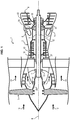
- the turbojet engine 1 comprises a housing 2, a fan 3, a low-pressure body 4, a high-pressure body 5 and a combustion chamber 6.
- the low-pressure body 4 comprises a low-pressure compressor 7, a low-pressure turbine 8 and a low-pressure turbine shaft 9 connecting the low-pressure compressor 7 to the low-pressure turbine 8.
- the low-pressure turbine shaft 9 extends along a longitudinal axis X of the turbojet engine 1.
- the low-pressure turbine 8 is able to drive the low-pressure compressor 7 into rotation via the low-pressure turbine shaft 9.
- the entire low-pressure body 4 is thus driven in rotation with respect to the casing 2 around the X axis.
- the high pressure body 5 comprises a high pressure compressor 10, a high pressure turbine 11 and a high pressure compressor shaft 12 connecting the high pressure compressor 10 to the high pressure turbine 11.
- the high pressure compressor shaft 12 extends around the low pressure turbine shaft 9 concentrically thereto (i.e., centered on the X axis).
- the high-pressure turbine 11 is capable of rotating the high-pressure compressor 10 via the high-pressure compressor shaft 12. The entire high-pressure body 5 is thus driven in rotation with respect to the casing 2 about the X axis. .
- the low pressure 4 and high pressure 5 bodies are rotated relative to the housing 2 independently of one another.
- the turbine shaft 9 and the compressor shaft 12 are rotated independently of one another about the longitudinal axis X of the turbojet engine 1.
- the primary air flow 14 flows through the turbojet 1 upstream downstream passing successively through the low pressure compressor 7, the high pressure compressor 10, the combustion chamber 6 where it is mixed with fuel for be burned, the high pressure turbine 11 and the low pressure turbine 8.
- the passage of the air flow primary 14 through the high-pressure turbine 11 and the low-pressure turbine 8 causes a rotation of the turbines 11 and 8 which in turn drive the high-pressure compressor 10 and the low-pressure compressor 7, as well as the fan 3, via the turbine shaft 9 and the compressor shaft 12.
- the shafts 9 and 12 are supported and guided in rotation by bearings 16, 17, 18 and 19 which are housed in pressurized bearing chambers.
- first bearing 16 and the second bearing 17 are interposed between a disk carrier 20 of the low-pressure compressor and the casing 2 of the turbojet engine.
- the third bearing 18 (called “bearing No. 3") is disposed at a first end 21 of the high-pressure compressor shaft 12, the first end 21 being connected to the high-pressure turbine 11.
- the third bearing 18 is interposed between the high-pressure compressor shaft 12 and the casing 2.
- the fourth bearing 19 (called “bearing No. 4") is disposed at a second end 22 of the high-pressure compressor shaft 12, the second end 22 being connected to the high-pressure compressor 10.
- the fourth bearing 19 is interposed between the high pressure compressor shaft 12 and the low pressure turbine shaft 9.
- the high pressure compressor shaft 12 comprises at its second end 22, a conventional end pin 23.
- the bearing 19 is interposed between the low-pressure turbine shaft 9 and the journal 23 of the high-pressure compressor shaft 12.
- the journal 23 is fixed to the disc 39 of the high-pressure turbine 10 by means of a bolted flange 40.
- the journal 23 is rotatably connected to the high-pressure compressor shaft 12 by virtue of the flange 40. .
- the outer ring 28 of the bearing 19 is fixed on the pin by means of a nut 29 (called “nut bearing No. 4"), a pin 30 and an elastic ring 31 (circlip) held in an annular groove 37 of the journal 23.
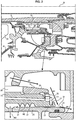
- the trunnion 23 + disc 39 + outer ring 28 + nut 29 assembly has an inner surface 24 extending facing the low pressure turbine shaft 9.
- the inner surface 24 is flared downstream of the turbojet engine 1 so as to guide the oil H1 flowing along its inner surface 24 towards the downstream of the turbojet engine by centrifugal effect when the high pressure compressor shaft 12 is driven by rotation.
- the oil H1 used to lubricate the bearing 19 is thus discharged to the bearing chamber for recycling.
- journal 23 has an external surface 25 extending facing an inner surface 34 of the seal support 26 of the low-pressure turbine 8.
- the outer surface 25 of the trunnion 23 comprises a series of radial wipers 27 forming a sealing labyrinth between the trunnion 23 and the joint support 26 of the low-pressure turbine 8.
- the seal support 26 of the low-pressure turbine 8 also has an internal surface 34 having a flared portion 33 downstream of the turbojet engine 1 so as to guide the oil H1 flowing along its inner surface 34 downstream of the engine 1. turbojet by centrifugal effect.
- H2 oil can penetrate between the trunnion 23 and the seal support 26, up along the joint support 26 downstream of the turbojet engine 1.
- the H2 oil can thus infiltrate hot parts of the turbojet engine 1 and cause the appearance of undesirable fumes. This phenomenon has been observed in particular when the turbojet engine 1 operates at low speed, and the centrifugal effect is not sufficient to counter the penetration of the H2 oil between the trunnion 23 and the gasket support 26.
- the high pressure compressor shaft 12 comprises an end journal 23 according to one embodiment of the invention.
- the bearing 19 is interposed between the low-pressure turbine shaft 9 and the journal 23 of the high-pressure compressor shaft 12.
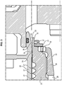
- the journal 23 shown on the figures 3 and 4 differs from the trunnion 23 of the figure 2 , in that it comprises a droplet extension 32 extending opposite the flared portion 33 of the inner surface 34 of the joint support 26.
- the droplet extension 32 extends beyond the annular groove 37 formed in the trunnion 23 to receive the elastic ring 31.
- the H2 oil is then guided, by centrifugal effect, along the inner surface 33 of the seal support downstream of the turbojet engine 1 to be recycled.
- journal 23 comprises a recess 38 formed in the outer surface 25 of the journal, the recess 38 being in the form of an annular groove.
- the annular groove 38 stops the penetration of the oil H2 between the outer surface 25 of the pin 23 and the inner surface 34 of the seal support 26 causing the oil to detach towards the flared portion 33 of the inner surface 34 of the support seal 26 by centrifugal effect.
- the droplet extension 32 has an outer surface 35 inclined relative to the axis of rotation X of the high pressure compressor shaft 12.
- the inclination of the outer surface 35 is such that the outer surface 35 tends to guide the H2 oil to the recess 38 by centrifugal effect when the pin 23 is rotated.
- the trunnion 23 comprises a series of radial wipers 27 forming a sealing labyrinth between the outer surface 25 of the trunnion 23 and the inner surface 34 of the joint support 26.
Landscapes
- Engineering & Computer Science (AREA)
- Chemical & Material Sciences (AREA)
- Combustion & Propulsion (AREA)
- Mechanical Engineering (AREA)
- General Engineering & Computer Science (AREA)
- Turbine Rotor Nozzle Sealing (AREA)
- Structures Of Non-Positive Displacement Pumps (AREA)
- Sealing Using Fluids, Sealing Without Contact, And Removal Of Oil (AREA)
Description
- L'invention concerne un tourillon pour turbine haute pression, et un turboréacteur incluant un tel tourillon.
- Les turboréacteurs double corps comprennent deux corps rotatifs : un corps basse pression et un corps haute pression, dont les rotations sont indépendantes. Chaque corps inclut un compresseur et une turbine entraînant le compresseur. A cet effet, chaque corps inclut également un arbre reliant la turbine au compresseur pour entrainer le compresseur en rotation.
- L'arbre de turbine basse pression relie le compresseur basse pression à la turbine basse pression, L'arbre de compresseur haute pression relie le compresseur haute pression à la turbine haute pression,
- Dans un tel turboréacteur, l'arbre de compresseur haute pression s'étend autour de l'arbre de turbine basse pression, de manière concentrique.
- Par ailleurs, l'arbre de compresseur haute pression comprend un tourillon d'extrémité agencé au niveau de l'extrémité réceptrice de l'arbre (extrémité reliée à la turbine haute pression). Le tourillon d'extrémité a pour fonction de supporter le palier n°4 disposé entre l'arbre de compresseur haute pression et l'arbre de turbine basse pression.
- La lubrification du palier est assurée par une mise en circulation d'huile à travers le palier. Grâce à l'effet centrifuge produit par la rotation de l'arbre de compresseur haute pression, l'huile circule à travers le palier et est évacuée vers l'aval du turboréacteur pour être recyclée.
- Lors de la mise en marche d'un tel turboréacteur, on a pu constater l'apparition de fumées.
- Un but de l'invention est de réduire les fumées produites lors du démarrage du turboréacteur.
- Des investigations menées par les inventeurs ont mis en évidence que la production de fumées était due à une accumulation d'huile dans certaines zones chaudes du turboréacteur, cette accumulation d'huile provenant d'un refoulement de l'huile vers l'amont du turboréacteur, se produisant en particulier lorsque le turboréacteur tourne à bas régime.
- Ce problème est résolu dans le cadre de la présente invention grâce à un tourillon pour turbine haute pression, selon la revendication 1, qui est destiné à être disposé entre un arbre de turbine basse pression et une surface interne d'un support de joint de turbine basse pression, le tourillon étant caractérisé en ce qu'il comprend une extension lance-goutte agencée pour s'étendre en regard d'une partie évasée de la surface interne du support de joint, de manière à ce que lorsque le tourillon est entrainé en rotation autour de l'arbre de turbine basse pression, de l'huile tendant à pénétrer entre le tourillon et le support de joint est projetée par effet centrifuge depuis l'extension lance-goutte vers la partie évasée de la surface interne du support de joint.
- L'extension lance-goutte permet de projeter l'huile circulant le long du tourillon vers la partie évasée de la surface interne du support de joint, avant que l'huile n'ait pu pénétrer entre le tourillon et le support de joint. Cet agencement limite donc une remontée de l'huile vers l'amont du turboréacteur.
- Le tourillon comprend un renfoncement ménagé dans la surface externe du tourillon, le renfoncement stoppant la pénétration de l'huile entre le tourillon et le support de joint et provoquant un décollement de l'huile vers la surface interne du support de joint par effet centrifuge. Le tourillon est remarquable par le fait que l'extension lance-goutte présente une surface externe inclinée par rapport à un axe de rotation du tourillon, tendant à guider l'huile vers le renfoncement par effet centrifuge lorsque le tourillon est entraîné en rotation.
- Le tourillon peut en outre présenter les caractéristiques suivantes :
- le renfoncement est une gorge annulaire ménagée dans la surface externe du tourillon,
- le tourillon comprend une série de léchettes radiales propre à former un labyrinthe d'étanchéité entre le tourillon et le support de joint.
- L'invention se rapporte en outre à un turboréacteur comprenant un compresseur basse pression, un compresseur haute pression, une turbine haute pression et une turbine basse pression, le turboréacteur comprenant en outre :
- un arbre de turbine basse pression reliant le compresseur basse pression à la turbine basse pression,
- un arbre de compresseur haute pression s'étendant autour de l'arbre de turbine basse pression, et reliant le compresseur haute pression à la turbine haute pression,
- D'autres caractéristiques et avantages ressortiront encore de la description qui suit, laquelle est purement illustrative et non limitative et doit être lue en regard des figures annexées, parmi lesquelles :
- la
figure 1 représente de manière schématique, en coupe longitudinale, un turboréacteur double corps, - la
figure 2 représente de manière schématique la circulation de l'huile servant à lubrifier le palier n°4 dans un turboréacteur comprenant un tourillon conventionnel, - les
figures 3 et4 représentent de manière schématique la circulation de l'huile servant à lubrifier le palier n°4 dans un turboréacteur comprenant un tourillon conforme à un mode de réalisation de l'invention. - Sur la
figure 1 , le turboréacteur 1 représenté comprend un carter 2, une soufflante 3, un corps basse pression 4, un corps haute pression 5 et une chambre de combustion 6. - Le corps basse pression 4 comprend un compresseur basse pression 7, une turbine basse pression 8 et un arbre de turbine basse pression 9 reliant le compresseur basse pression 7 à la turbine basse pression 8. L'arbre de turbine basse pression 9 s'étend selon un axe longitudinal X du turboréacteur 1. La turbine basse pression 8 est apte à entrainer en rotation le compresseur basse pression 7 via l'arbre de turbine basse pression 9. L'ensemble du corps basse pression 4 est ainsi entrainé en rotation par rapport au carter 2 autour de l'axe X.
- Le corps haute pression 5 comprend un compresseur haute pression 10, une turbine haute pression 11 et un arbre de compresseur haute pression 12 reliant le compresseur haute pression 10 à la turbine haute pression 11. L'arbre de compresseur haute pression 12 s'étend autour de l'arbre de turbine basse pression 9 de manière concentrique à celui-ci (c'est-à-dire centré sur l'axe X). La turbine haute pression 11 est apte à entrainer en rotation le compresseur haute pression 10 via l'arbre de compresseur haute pression 12. L'ensemble du corps haute pression 5 est ainsi entrainé en rotation par rapport au carter 2 autour de l'axe X.
- En fonctionnement, les corps basse pression 4 et haute pression 5 sont entrainés en rotation par rapport au carter 2 indépendamment l'un de l'autre. Ainsi, l'arbre de turbine 9 et l'arbre de compresseur 12 sont entrainés en rotation indépendamment l'un de l'autre autour de l'axe longitudinal X du turboréacteur 1.
- Lorsque le turboréacteur 1 est en marche, de l'air 13 est aspiré par la soufflante 3 et est divisé en un flux d'air primaire 14 et un flux d'air secondaire 15, qui circulent d'amont en aval du turboréacteur 1.
- Le flux d'air primaire 14 s'écoule à travers le turboréacteur 1 d'amont en aval en passant successivement à travers le compresseur basse pression 7, le compresseur haute pression 10, la chambre de combustion 6 où il est mélangé avec du carburant pour être brûlé, la turbine haute pression 11 et la turbine basse pression 8. Le passage du flux d'air primaire 14 à travers la turbine haute pression 11 et la turbine basse pression 8 provoque une rotation des turbines 11 et 8 qui entrainent à leur tour en rotation le compresseur haute pression 10 et le compresseur basse pression 7, ainsi que la soufflante 3, via l'arbre de turbine 9 et l'arbre de compresseur 12.
- Les arbres 9 et 12 sont supportés et guidés en rotation par des paliers 16, 17, 18 et 19 qui sont logés dans des chambres-palier pressurisées.
- Ainsi, le premier palier 16 et le deuxième palier 17 (appelés respectivement « paliers n°1 » et « palier n°2 ») sont interposés entre un support de disques 20 du compresseur basse pression et le carter 2 du turboréacteur.
- Le troisième palier 18 (appelé « palier n°3 ») est disposé à une première extrémité 21 de l'arbre de compresseur haute pression 12, la première extrémité 21 étant reliée à la turbine haute pression 11. Le troisième palier 18 est interposé entre l'arbre de compresseur haute pression 12 et le carter 2.
- Le quatrième palier 19 (appelé « palier n°4 ») est disposé à une deuxième extrémité 22 de l'arbre de compresseur haute pression 12, la deuxième extrémité 22 étant reliée au compresseur haute pression 10. Le quatrième palier 19 est interposé entre l'arbre de compresseur haute pression 12 et l'arbre de turbine basse pression 9.
- Sur la
figure 2 , l'arbre de compresseur haute pression 12 comprend au niveau de sa deuxième extrémité 22, un tourillon d'extrémité 23 conventionnel. Le palier 19 est interposé entre l'arbre de turbine basse pression 9 et le tourillon 23 de l'arbre de compresseur haute pression 12. - Le tourillon 23 est fixé au disque 39 de la turbine haute pression 10 par l'intermédiaire d'une bride boulonnée 40. Autrement dit, le tourillon 23 est rendu solidaire en rotation de l'arbre de compresseur haute pression 12 grâce à la bride 40.
- Par ailleurs, la bague externe 28 du palier 19 est fixée sur le tourillon par le biais d'un écrou 29 (appelé « écrou palier n°4 »), d'un pion 30 et d'un anneau élastique 31 (circlip) maintenu dans une gorge annulaire 37 du tourillon 23.
- L'ensemble tourillon 23 + disque 39 + bague externe 28 + écrou 29 présente une surface interne 24 s'étendant en regard de l'arbre de turbine basse pression 9.
- La surface interne 24 est évasée vers l'aval du turboréacteur 1 de manière à guider l'huile H1 circulant le long de sa surface interne 24 vers l'aval du turboréacteur par effet centrifuge lorsque l'arbre de compresseur haute pression 12 est entrainé en rotation. L'huile H1 servant à lubrifier le palier 19 est ainsi évacuée vers la chambre-palier en vue d'être recyclée.
- De plus, le tourillon 23 présente une surface externe 25 s'étendant en regard d'une surface interne 34 du support de joint 26 de la turbine basse pression 8.
- La surface externe 25 du tourillon 23 comprend une série de léchettes radiales 27 formant un labyrinthe d'étanchéité entre le tourillon 23 et le support de joint 26 de la turbine basse pression 8.
- De plus, de l'air est injecté entre la surface externe 25 du tourillon et la surface interne 34 du support de joint afin de maintenir sous pression la chambre-palier du palier 19.
- Le support de joint 26 de la turbine basse pression 8 présente également une surface interne 34 ayant une partie évasée 33 vers l'aval du turboréacteur 1 de manière à guider l'huile H1 circulant le long de sa surface interne 34 vers l'aval du turboréacteur par effet centrifuge.
- Comme cela est illustré sur la
figure 2 , il a été constaté que lorsque l'arbre haute pression 12 est entrainé en rotation autour de l'axe X, de l'huile H2 peut pénétrer entre le tourillon 23 et le support de joint 26, en remontant le long du support de joint 26 vers l'aval du turboréacteur 1. L'huile H2 peut ainsi infiltrer des parties chaudes du turboréacteur 1 et provoquer l'apparition de fumées indésirables. Ce phénomène a été constaté en particulier lorsque le turboréacteur 1 fonctionne à bas régime, et que l'effet centrifuge ne suffit pas à contrer la pénétration de l'huile H2 entre le tourillon 23 et le support de joint 26. - Sur les
figures 3 et4 , l'arbre de compresseur haute pression 12 comprend un tourillon d'extrémité 23 conforme à un mode de réalisation de l'invention. - Le palier 19 est interposé entre l'arbre de turbine basse pression 9 et le tourillon 23 de l'arbre de compresseur haute pression 12.
- Le tourillon 23 représenté sur les
figures 3 et4 diffère du tourillon 23 de lafigure 2 , en ce qu'il comprend une extension lance-goutte 32 s'étendant en regard de la partie évasée 33 de la surface interne 34 du support de joint 26. - L'extension lance-goutte 32 s'étend au-delà de la gorge annulaire 37 ménagée dans le tourillon 23 pour recevoir l'anneau élastique 31.
- De cette manière, lorsque le tourillon 23 est entrainé en rotation autour de l'arbre de turbine basse pression 9, de l'huile H2 tendant à pénétrer entre la surface externe 25 du tourillon 23 et la surface interne 34 du support de joint 26 est projetée par effet centrifuge depuis l'extension lance-goutte 32 vers la partie évasée 33 de la surface interne 34 du support de joint 26.
- L'huile H2 est ensuite guidée, par effet centrifuge, le long de la surface interne 33 du support de joint vers l'aval du turboréacteur 1 pour être recyclée.
- De plus, le tourillon 23 comprend un renfoncement 38 ménagé dans la surface externe 25 du tourillon, le renfoncement 38 étant réalisé sous la forme d'une gorge annulaire.
- La gorge annulaire 38 stoppe la pénétration de l'huile H2 entre la surface externe 25 du tourillon 23 et la surface interne 34 du support de joint 26 en provoquant un décollement de l'huile vers la partie évasée 33 de la surface interne 34 du support de joint 26 par effet centrifuge.
- De plus, l'extension lance-goutte 32 présente une surface externe 35 inclinée par rapport à l'axe de rotation X de l'arbre de compresseur haute pression 12. L'inclinaison de la surface externe 35 est telle que la surface externe 35 tend à guider l'huile H2 vers le renfoncement 38 par effet centrifuge lorsque le tourillon 23 est entrainé en rotation.
- Enfin, le tourillon 23 comprend une série de léchettes radiales 27 formant un labyrinthe d'étanchéité entre la surface externe 25 du tourillon 23 et la surface interne 34 du support de joint 26.
Claims (4)
- Tourillon (23) pour turbine haute pression (11), destiné à être disposé entre un arbre de turbine basse pression (9) et une surface interne (34) d'un support de joint (26) de turbine basse pression (8), le tourillon (23) comprenant une extension lance-goutte (32) agencée pour s'étendre en regard d'une partie évasée (33) de la surface interne (34) du support de joint (26), de manière à ce que lorsque le tourillon (23) est entrainé en rotation autour de l'arbre de turbine basse pression (9), de l'huile (H2) tendant à pénétrer entre le tourillon (23) et le support de joint (26) est projetée par effet centrifuge depuis l'extension lance-goutte (32) vers la partie évasée (33) de la surface interne (34) du support de joint (26), le tourillon comprenant en outre un renfoncement (38) ménagé dans la surface externe (25) du tourillon (23), le renfoncement (38) stoppant la pénétration de l'huile (H2) entre le tourillon (23) et le support de joint (26) et provoquant un décollement de l'huile (H2) vers la surface interne (34) du support de joint (26) par effet centrifuge, dans lequel l'extension lance-goutte (32) présente une surface externe (35) inclinée par rapport à un axe de rotation (X) du tourillon (23), tendant à guider l'huile (H2) vers le renfoncement (38) par effet centrifuge lorsque le tourillon (23) est entrainé en rotation.
- Tourillon selon la revendication 1, dans lequel le renfoncement (38) est une gorge annulaire ménagée dans la surface externe (25) du tourillon (23).
- Tourillon selon l'une des revendications qui précèdent, comprenant une série de léchettes radiales (27) propre à former un labyrinthe d'étanchéité entre le tourillon (23) et le support de joint (26).
- Turboréacteur (1) comprenant un compresseur basse pression (7), un compresseur haute pression (10), une turbine haute pression (11) et une turbine basse pression (8), le turboréacteur (1) comprenant en outre :- un arbre de turbine basse pression (9) reliant le compresseur basse pression (7) à la turbine basse pression (8),- un arbre de compresseur haute pression (12) s'étendant autour de l'arbre de turbine basse pression (9), et reliant le compresseur haute pression (10) à la turbine haute pression (11),dans lequel la turbine basse pression (8) comprend un support de joint (26) présentant une surface interne (34) ayant une partie évasée (33) et la turbine haute pression (11) comprend un tourillon (23) conforme à l'une des revendications 1 à 3, disposé entre l'arbre de turbine basse pression (9) et la surface interne (34) du support de joint (26) de la turbine basse pression (9).
Applications Claiming Priority (2)
| Application Number | Priority Date | Filing Date | Title |
|---|---|---|---|
| FR1355443A FR3007069B1 (fr) | 2013-06-12 | 2013-06-12 | Tourillon pour turbine haute pression, et turboreacteur incluant un tel tourillon |
| PCT/FR2014/051420 WO2014199083A1 (fr) | 2013-06-12 | 2014-06-11 | Tourillon pour turbine haute pression, et turboreacteur incluant un tel tourillon |
Publications (2)
| Publication Number | Publication Date |
|---|---|
| EP3008296A1 EP3008296A1 (fr) | 2016-04-20 |
| EP3008296B1 true EP3008296B1 (fr) | 2017-04-12 |
Family
ID=48795840
Family Applications (1)
| Application Number | Title | Priority Date | Filing Date |
|---|---|---|---|
| EP14734885.8A Active EP3008296B1 (fr) | 2013-06-12 | 2014-06-11 | Tourillon pour turbine haute pression, et turboreacteur incluant un tel tourillon |
Country Status (9)
| Country | Link |
|---|---|
| US (1) | US10113480B2 (fr) |
| EP (1) | EP3008296B1 (fr) |
| JP (1) | JP6333968B2 (fr) |
| CN (1) | CN105308271B (fr) |
| BR (1) | BR112015031029B1 (fr) |
| CA (1) | CA2915106C (fr) |
| FR (1) | FR3007069B1 (fr) |
| RU (1) | RU2657105C2 (fr) |
| WO (1) | WO2014199083A1 (fr) |
Families Citing this family (4)
| Publication number | Priority date | Publication date | Assignee | Title |
|---|---|---|---|---|
| JP6409038B2 (ja) | 2016-09-30 | 2018-10-17 | 株式会社Subaru | 車両の乗員保護装置 |
| FR3062688B1 (fr) * | 2017-02-07 | 2019-04-19 | Safran Aircraft Engines | Agencement d'assemblage d'un disque de turbine a une bride d'un tourillon dans un turboreacteur |
| BE1026411B1 (fr) * | 2018-06-21 | 2020-01-30 | Safran Aero Boosters Sa | Virole extérieure de turbomachine |
| FR3137407B1 (fr) * | 2022-06-30 | 2024-05-24 | Safran Aircraft Engines | Turbomachine comportant un dispositif de recuperation d’huile ameliore |
Family Cites Families (18)
| Publication number | Priority date | Publication date | Assignee | Title |
|---|---|---|---|---|
| GB0305974D0 (en) * | 2003-03-15 | 2003-04-23 | Rolls Royce Plc | A seal |
| FR2858649B1 (fr) * | 2003-08-05 | 2005-09-23 | Snecma Moteurs | Turbine basse-pression de turbomachine |
| GB0414170D0 (en) * | 2004-06-24 | 2004-07-28 | Rolls Royce Plc | A bearing arrangement |
| FR2877036B1 (fr) * | 2004-10-27 | 2006-12-22 | Snecma Moteurs Sa | Dispositif de lubrification d'un composant dans une turbomachine |
| US7334982B2 (en) * | 2005-05-06 | 2008-02-26 | General Electric Company | Apparatus for scavenging lubricating oil |
| US7581889B2 (en) * | 2006-09-08 | 2009-09-01 | Pratt & Whitney Canada Corp. | Integral tandem bearing for high speed flexible shafts |
| US7967560B2 (en) * | 2006-11-07 | 2011-06-28 | United Technologies Corporation | Radially energized oil capture device for a geared turbofan |
| GB0623705D0 (en) * | 2006-11-28 | 2007-01-10 | Cummins Turbo Tech Ltd | Hydraulic for a turbocharger |
| DE102007027869B4 (de) * | 2007-06-18 | 2010-04-29 | Continental Automotive Gmbh | Turbolader mit einem Turboladergehäuse |
| FR2917783B1 (fr) * | 2007-06-25 | 2013-04-12 | Snecma | Systeme de liaison d'arbre moteur avec ecrou auto-extracteur |
| GB0720479D0 (en) * | 2007-10-13 | 2007-11-28 | Cummins Turbo Tech Ltd | Rotating machine and oil control device |
| DE102007060890A1 (de) * | 2007-12-14 | 2009-06-18 | Rolls-Royce Deutschland Ltd & Co Kg | Abdichtung mindestens einer Welle mit mindestens einer hydraulischen Dichtung |
| FR2927366B1 (fr) * | 2008-02-13 | 2013-07-05 | Snecma | Dispositif de recuperation d'huile. |
| FR2950109B1 (fr) * | 2009-09-17 | 2012-07-27 | Turbomeca | Turbomoteur a arbres paralleles |
| FR2957976B1 (fr) * | 2010-03-26 | 2013-04-12 | Snecma | Dispositif d'etancheite pour une enceinte d'huile d'un turboreacteur |
| FR2976316B1 (fr) * | 2011-06-08 | 2013-06-14 | Snecma | Turbomachine comportant un palier flottant de guidage d'un arbre de turbomachine |
| JP6145959B2 (ja) * | 2011-07-12 | 2017-06-14 | 株式会社Ihi | ターボチャージャ |
| US9316119B2 (en) * | 2011-09-15 | 2016-04-19 | United Technologies Corporation | Turbomachine secondary seal assembly |
-
2013
- 2013-06-12 FR FR1355443A patent/FR3007069B1/fr active Active
-
2014
- 2014-06-11 WO PCT/FR2014/051420 patent/WO2014199083A1/fr not_active Ceased
- 2014-06-11 US US14/897,607 patent/US10113480B2/en active Active
- 2014-06-11 CA CA2915106A patent/CA2915106C/fr active Active
- 2014-06-11 JP JP2016518569A patent/JP6333968B2/ja active Active
- 2014-06-11 RU RU2015155828A patent/RU2657105C2/ru active
- 2014-06-11 CN CN201480034003.5A patent/CN105308271B/zh active Active
- 2014-06-11 EP EP14734885.8A patent/EP3008296B1/fr active Active
- 2014-06-11 BR BR112015031029-0A patent/BR112015031029B1/pt active IP Right Grant
Non-Patent Citations (1)
| Title |
|---|
| None * |
Also Published As
| Publication number | Publication date |
|---|---|
| RU2015155828A (ru) | 2017-07-17 |
| BR112015031029B1 (pt) | 2021-12-21 |
| US20160186656A1 (en) | 2016-06-30 |
| CN105308271A (zh) | 2016-02-03 |
| CA2915106A1 (fr) | 2014-12-18 |
| RU2015155828A3 (fr) | 2018-05-07 |
| JP6333968B2 (ja) | 2018-05-30 |
| CA2915106C (fr) | 2021-02-23 |
| BR112015031029A2 (pt) | 2017-07-25 |
| JP2016521823A (ja) | 2016-07-25 |
| WO2014199083A1 (fr) | 2014-12-18 |
| FR3007069A1 (fr) | 2014-12-19 |
| CN105308271B (zh) | 2017-06-16 |
| FR3007069B1 (fr) | 2015-07-17 |
| RU2657105C2 (ru) | 2018-06-08 |
| EP3008296A1 (fr) | 2016-04-20 |
| US10113480B2 (en) | 2018-10-30 |
Similar Documents
| Publication | Publication Date | Title |
|---|---|---|
| EP3857040B1 (fr) | Turbomachine à réducteur pour un aéronef | |
| CA2944835C (fr) | Compresseur de turbomachine a aubes a calage variable | |
| CA2952506C (fr) | Dispositif et procede de lubrification d'un palier a roulement de turbomachine | |
| WO2008071651A2 (fr) | Procede et systeme de lubrification d'une turbomachine | |
| FR2858649A1 (fr) | Turbine basse-pression de turbomachine | |
| EP1965041B1 (fr) | Système de déshuilage pour moteur d`aéronef | |
| FR2977636A1 (fr) | Dispositif de lubrification d'un palier a roulement inter-arbres de turbopropulseur a double helice | |
| FR2940351A1 (fr) | Rotor de turbine d'un moteur a turbine a gaz comprenant un disque de rotor et un flasque d'etancheite | |
| CA2945890C (fr) | Pompe a engrenages a carburant, prevue notamment comme pompe a haute pression | |
| EP3430243B1 (fr) | Turboréacteur ayant un groupe lubrification des paliers simplifié | |
| EP3008296A1 (fr) | Tourillon pour turbine haute pression, et turboreacteur incluant un tel tourillon | |
| FR3114353A1 (fr) | Joint dynamique amélioré pour l’étanchéité d’un module de moteur d’aéronef | |
| CA2682004A1 (fr) | Double joint a levre pressurise | |
| FR2983908A1 (fr) | Systeme pour assurer l'etancheite entre une enceinte d'huile et un volume exterieur attenant et turbomachine equipee d'un tel systeme d'etancheite. | |
| EP1653052B1 (fr) | Dispositif de lubrification d'un composant dans une turbomachine | |
| EP2836685B1 (fr) | Dispositif d'etancheite inter-arbres coaxiaux d'une turbomachine | |
| FR2983909A1 (fr) | Enceinte lubrifiee logeant un palier inter-turbine et fermee par un joint a labyrinthe a faible usure | |
| FR3049006A1 (fr) | Turboreacteur ayant un groupe lubrification des paliers simplifie | |
| FR3066533B1 (fr) | Ensemble d'etancheite pour une turbomachine | |
| EP4062041B1 (fr) | Dispositif d'alimentation en carburant d'une chambre de combustion d'un générateur de gaz | |
| EP4374048B1 (fr) | Manchon rapporté sur un arbre basse pression dans une turbomachine | |
| EP3935273B1 (fr) | Turbine à gaz contrarotative pour aéronef à double rotor | |
| FR3148260A1 (fr) | Démarreur de turbine à air | |
| FR3057907B1 (fr) | Ensemble a effet anti-usure pour turboreacteur | |
| WO2022069824A1 (fr) | Support statorique pour un arbre de soufflante entraine par une boite de reduction de vitesse dans une turbomachine |
Legal Events
| Date | Code | Title | Description |
|---|---|---|---|
| PUAI | Public reference made under article 153(3) epc to a published international application that has entered the european phase |
Free format text: ORIGINAL CODE: 0009012 |
|
| 17P | Request for examination filed |
Effective date: 20160106 |
|
| AK | Designated contracting states |
Kind code of ref document: A1 Designated state(s): AL AT BE BG CH CY CZ DE DK EE ES FI FR GB GR HR HU IE IS IT LI LT LU LV MC MK MT NL NO PL PT RO RS SE SI SK SM TR |
|
| AX | Request for extension of the european patent |
Extension state: BA ME |
|
| DAX | Request for extension of the european patent (deleted) | ||
| GRAP | Despatch of communication of intention to grant a patent |
Free format text: ORIGINAL CODE: EPIDOSNIGR1 |
|
| INTG | Intention to grant announced |
Effective date: 20161123 |
|
| GRAS | Grant fee paid |
Free format text: ORIGINAL CODE: EPIDOSNIGR3 |
|
| GRAJ | Information related to disapproval of communication of intention to grant by the applicant or resumption of examination proceedings by the epo deleted |
Free format text: ORIGINAL CODE: EPIDOSDIGR1 |
|
| GRAL | Information related to payment of fee for publishing/printing deleted |
Free format text: ORIGINAL CODE: EPIDOSDIGR3 |
|
| GRAP | Despatch of communication of intention to grant a patent |
Free format text: ORIGINAL CODE: EPIDOSNIGR1 |
|
| INTC | Intention to grant announced (deleted) | ||
| GRAA | (expected) grant |
Free format text: ORIGINAL CODE: 0009210 |
|
| INTG | Intention to grant announced |
Effective date: 20170213 |
|
| AK | Designated contracting states |
Kind code of ref document: B1 Designated state(s): AL AT BE BG CH CY CZ DE DK EE ES FI FR GB GR HR HU IE IS IT LI LT LU LV MC MK MT NL NO PL PT RO RS SE SI SK SM TR |
|
| REG | Reference to a national code |
Ref country code: GB Ref legal event code: FG4D Free format text: NOT ENGLISH |
|
| REG | Reference to a national code |
Ref country code: CH Ref legal event code: EP |
|
| REG | Reference to a national code |
Ref country code: IE Ref legal event code: FG4D Free format text: LANGUAGE OF EP DOCUMENT: FRENCH |
|
| REG | Reference to a national code |
Ref country code: AT Ref legal event code: REF Ref document number: 884109 Country of ref document: AT Kind code of ref document: T Effective date: 20170515 |
|
| REG | Reference to a national code |
Ref country code: DE Ref legal event code: R096 Ref document number: 602014008588 Country of ref document: DE Ref country code: FR Ref legal event code: PLFP Year of fee payment: 4 |
|
| REG | Reference to a national code |
Ref country code: SE Ref legal event code: TRGR |
|
| REG | Reference to a national code |
Ref country code: NL Ref legal event code: MP Effective date: 20170412 |
|
| REG | Reference to a national code |
Ref country code: LT Ref legal event code: MG4D |
|
| REG | Reference to a national code |
Ref country code: AT Ref legal event code: MK05 Ref document number: 884109 Country of ref document: AT Kind code of ref document: T Effective date: 20170412 |
|
| PG25 | Lapsed in a contracting state [announced via postgrant information from national office to epo] |
Ref country code: NL Free format text: LAPSE BECAUSE OF FAILURE TO SUBMIT A TRANSLATION OF THE DESCRIPTION OR TO PAY THE FEE WITHIN THE PRESCRIBED TIME-LIMIT Effective date: 20170412 |
|
| PG25 | Lapsed in a contracting state [announced via postgrant information from national office to epo] |
Ref country code: ES Free format text: LAPSE BECAUSE OF FAILURE TO SUBMIT A TRANSLATION OF THE DESCRIPTION OR TO PAY THE FEE WITHIN THE PRESCRIBED TIME-LIMIT Effective date: 20170412 Ref country code: LT Free format text: LAPSE BECAUSE OF FAILURE TO SUBMIT A TRANSLATION OF THE DESCRIPTION OR TO PAY THE FEE WITHIN THE PRESCRIBED TIME-LIMIT Effective date: 20170412 Ref country code: GR Free format text: LAPSE BECAUSE OF FAILURE TO SUBMIT A TRANSLATION OF THE DESCRIPTION OR TO PAY THE FEE WITHIN THE PRESCRIBED TIME-LIMIT Effective date: 20170713 Ref country code: FI Free format text: LAPSE BECAUSE OF FAILURE TO SUBMIT A TRANSLATION OF THE DESCRIPTION OR TO PAY THE FEE WITHIN THE PRESCRIBED TIME-LIMIT Effective date: 20170412 Ref country code: HR Free format text: LAPSE BECAUSE OF FAILURE TO SUBMIT A TRANSLATION OF THE DESCRIPTION OR TO PAY THE FEE WITHIN THE PRESCRIBED TIME-LIMIT Effective date: 20170412 Ref country code: NO Free format text: LAPSE BECAUSE OF FAILURE TO SUBMIT A TRANSLATION OF THE DESCRIPTION OR TO PAY THE FEE WITHIN THE PRESCRIBED TIME-LIMIT Effective date: 20170712 Ref country code: AT Free format text: LAPSE BECAUSE OF FAILURE TO SUBMIT A TRANSLATION OF THE DESCRIPTION OR TO PAY THE FEE WITHIN THE PRESCRIBED TIME-LIMIT Effective date: 20170412 |
|
| PG25 | Lapsed in a contracting state [announced via postgrant information from national office to epo] |
Ref country code: BG Free format text: LAPSE BECAUSE OF FAILURE TO SUBMIT A TRANSLATION OF THE DESCRIPTION OR TO PAY THE FEE WITHIN THE PRESCRIBED TIME-LIMIT Effective date: 20170712 Ref country code: IS Free format text: LAPSE BECAUSE OF FAILURE TO SUBMIT A TRANSLATION OF THE DESCRIPTION OR TO PAY THE FEE WITHIN THE PRESCRIBED TIME-LIMIT Effective date: 20170812 Ref country code: PL Free format text: LAPSE BECAUSE OF FAILURE TO SUBMIT A TRANSLATION OF THE DESCRIPTION OR TO PAY THE FEE WITHIN THE PRESCRIBED TIME-LIMIT Effective date: 20170412 Ref country code: LV Free format text: LAPSE BECAUSE OF FAILURE TO SUBMIT A TRANSLATION OF THE DESCRIPTION OR TO PAY THE FEE WITHIN THE PRESCRIBED TIME-LIMIT Effective date: 20170412 Ref country code: RS Free format text: LAPSE BECAUSE OF FAILURE TO SUBMIT A TRANSLATION OF THE DESCRIPTION OR TO PAY THE FEE WITHIN THE PRESCRIBED TIME-LIMIT Effective date: 20170412 |
|
| REG | Reference to a national code |
Ref country code: DE Ref legal event code: R097 Ref document number: 602014008588 Country of ref document: DE |
|
| PG25 | Lapsed in a contracting state [announced via postgrant information from national office to epo] |
Ref country code: EE Free format text: LAPSE BECAUSE OF FAILURE TO SUBMIT A TRANSLATION OF THE DESCRIPTION OR TO PAY THE FEE WITHIN THE PRESCRIBED TIME-LIMIT Effective date: 20170412 Ref country code: DK Free format text: LAPSE BECAUSE OF FAILURE TO SUBMIT A TRANSLATION OF THE DESCRIPTION OR TO PAY THE FEE WITHIN THE PRESCRIBED TIME-LIMIT Effective date: 20170412 Ref country code: RO Free format text: LAPSE BECAUSE OF FAILURE TO SUBMIT A TRANSLATION OF THE DESCRIPTION OR TO PAY THE FEE WITHIN THE PRESCRIBED TIME-LIMIT Effective date: 20170412 Ref country code: SK Free format text: LAPSE BECAUSE OF FAILURE TO SUBMIT A TRANSLATION OF THE DESCRIPTION OR TO PAY THE FEE WITHIN THE PRESCRIBED TIME-LIMIT Effective date: 20170412 Ref country code: CZ Free format text: LAPSE BECAUSE OF FAILURE TO SUBMIT A TRANSLATION OF THE DESCRIPTION OR TO PAY THE FEE WITHIN THE PRESCRIBED TIME-LIMIT Effective date: 20170412 Ref country code: MC Free format text: LAPSE BECAUSE OF FAILURE TO SUBMIT A TRANSLATION OF THE DESCRIPTION OR TO PAY THE FEE WITHIN THE PRESCRIBED TIME-LIMIT Effective date: 20170412 |
|
| REG | Reference to a national code |
Ref country code: CH Ref legal event code: PL |
|
| PLBE | No opposition filed within time limit |
Free format text: ORIGINAL CODE: 0009261 |
|
| STAA | Information on the status of an ep patent application or granted ep patent |
Free format text: STATUS: NO OPPOSITION FILED WITHIN TIME LIMIT |
|
| PG25 | Lapsed in a contracting state [announced via postgrant information from national office to epo] |
Ref country code: SM Free format text: LAPSE BECAUSE OF FAILURE TO SUBMIT A TRANSLATION OF THE DESCRIPTION OR TO PAY THE FEE WITHIN THE PRESCRIBED TIME-LIMIT Effective date: 20170412 |
|
| 26N | No opposition filed |
Effective date: 20180115 |
|
| REG | Reference to a national code |
Ref country code: IE Ref legal event code: MM4A |
|
| PG25 | Lapsed in a contracting state [announced via postgrant information from national office to epo] |
Ref country code: LU Free format text: LAPSE BECAUSE OF NON-PAYMENT OF DUE FEES Effective date: 20170611 Ref country code: IE Free format text: LAPSE BECAUSE OF NON-PAYMENT OF DUE FEES Effective date: 20170611 Ref country code: CH Free format text: LAPSE BECAUSE OF NON-PAYMENT OF DUE FEES Effective date: 20170630 Ref country code: LI Free format text: LAPSE BECAUSE OF NON-PAYMENT OF DUE FEES Effective date: 20170630 |
|
| PG25 | Lapsed in a contracting state [announced via postgrant information from national office to epo] |
Ref country code: SI Free format text: LAPSE BECAUSE OF FAILURE TO SUBMIT A TRANSLATION OF THE DESCRIPTION OR TO PAY THE FEE WITHIN THE PRESCRIBED TIME-LIMIT Effective date: 20170412 |
|
| REG | Reference to a national code |
Ref country code: FR Ref legal event code: PLFP Year of fee payment: 5 |
|
| REG | Reference to a national code |
Ref country code: BE Ref legal event code: MM Effective date: 20170630 |
|
| PG25 | Lapsed in a contracting state [announced via postgrant information from national office to epo] |
Ref country code: BE Free format text: LAPSE BECAUSE OF NON-PAYMENT OF DUE FEES Effective date: 20170630 |
|
| PG25 | Lapsed in a contracting state [announced via postgrant information from national office to epo] |
Ref country code: MT Free format text: LAPSE BECAUSE OF FAILURE TO SUBMIT A TRANSLATION OF THE DESCRIPTION OR TO PAY THE FEE WITHIN THE PRESCRIBED TIME-LIMIT Effective date: 20170412 |
|
| PG25 | Lapsed in a contracting state [announced via postgrant information from national office to epo] |
Ref country code: HU Free format text: LAPSE BECAUSE OF FAILURE TO SUBMIT A TRANSLATION OF THE DESCRIPTION OR TO PAY THE FEE WITHIN THE PRESCRIBED TIME-LIMIT; INVALID AB INITIO Effective date: 20140611 |
|
| PG25 | Lapsed in a contracting state [announced via postgrant information from national office to epo] |
Ref country code: CY Free format text: LAPSE BECAUSE OF FAILURE TO SUBMIT A TRANSLATION OF THE DESCRIPTION OR TO PAY THE FEE WITHIN THE PRESCRIBED TIME-LIMIT Effective date: 20170412 |
|
| PG25 | Lapsed in a contracting state [announced via postgrant information from national office to epo] |
Ref country code: MK Free format text: LAPSE BECAUSE OF FAILURE TO SUBMIT A TRANSLATION OF THE DESCRIPTION OR TO PAY THE FEE WITHIN THE PRESCRIBED TIME-LIMIT Effective date: 20170412 |
|
| PG25 | Lapsed in a contracting state [announced via postgrant information from national office to epo] |
Ref country code: TR Free format text: LAPSE BECAUSE OF FAILURE TO SUBMIT A TRANSLATION OF THE DESCRIPTION OR TO PAY THE FEE WITHIN THE PRESCRIBED TIME-LIMIT Effective date: 20170412 |
|
| PG25 | Lapsed in a contracting state [announced via postgrant information from national office to epo] |
Ref country code: PT Free format text: LAPSE BECAUSE OF FAILURE TO SUBMIT A TRANSLATION OF THE DESCRIPTION OR TO PAY THE FEE WITHIN THE PRESCRIBED TIME-LIMIT Effective date: 20170412 |
|
| PG25 | Lapsed in a contracting state [announced via postgrant information from national office to epo] |
Ref country code: AL Free format text: LAPSE BECAUSE OF FAILURE TO SUBMIT A TRANSLATION OF THE DESCRIPTION OR TO PAY THE FEE WITHIN THE PRESCRIBED TIME-LIMIT Effective date: 20170412 |
|
| PGFP | Annual fee paid to national office [announced via postgrant information from national office to epo] |
Ref country code: DE Payment date: 20250618 Year of fee payment: 12 |
|
| PGFP | Annual fee paid to national office [announced via postgrant information from national office to epo] |
Ref country code: GB Payment date: 20250625 Year of fee payment: 12 |
|
| PGFP | Annual fee paid to national office [announced via postgrant information from national office to epo] |
Ref country code: FR Payment date: 20250623 Year of fee payment: 12 |
|
| PGFP | Annual fee paid to national office [announced via postgrant information from national office to epo] |
Ref country code: SE Payment date: 20250618 Year of fee payment: 12 |
|
| PGFP | Annual fee paid to national office [announced via postgrant information from national office to epo] |
Ref country code: IT Payment date: 20250630 Year of fee payment: 12 |