EP3007366A1 - Csi feedback method and device in large-scale antenna system - Google Patents
Csi feedback method and device in large-scale antenna system Download PDFInfo
- Publication number
- EP3007366A1 EP3007366A1 EP13885992.1A EP13885992A EP3007366A1 EP 3007366 A1 EP3007366 A1 EP 3007366A1 EP 13885992 A EP13885992 A EP 13885992A EP 3007366 A1 EP3007366 A1 EP 3007366A1
- Authority
- EP
- European Patent Office
- Prior art keywords
- time
- indication information
- average period
- propagation paths
- varying parameters
- Prior art date
- Legal status (The legal status is an assumption and is not a legal conclusion. Google has not performed a legal analysis and makes no representation as to the accuracy of the status listed.)
- Granted
Links
Images

Classifications
-
- H—ELECTRICITY
- H04—ELECTRIC COMMUNICATION TECHNIQUE
- H04B—TRANSMISSION
- H04B7/00—Radio transmission systems, i.e. using radiation field
- H04B7/02—Diversity systems; Multi-antenna system, i.e. transmission or reception using multiple antennas
- H04B7/04—Diversity systems; Multi-antenna system, i.e. transmission or reception using multiple antennas using two or more spaced independent antennas
- H04B7/06—Diversity systems; Multi-antenna system, i.e. transmission or reception using multiple antennas using two or more spaced independent antennas at the transmitting station
- H04B7/0613—Diversity systems; Multi-antenna system, i.e. transmission or reception using multiple antennas using two or more spaced independent antennas at the transmitting station using simultaneous transmission
- H04B7/0615—Diversity systems; Multi-antenna system, i.e. transmission or reception using multiple antennas using two or more spaced independent antennas at the transmitting station using simultaneous transmission of weighted versions of same signal
- H04B7/0619—Diversity systems; Multi-antenna system, i.e. transmission or reception using multiple antennas using two or more spaced independent antennas at the transmitting station using simultaneous transmission of weighted versions of same signal using feedback from receiving side
- H04B7/0621—Feedback content
- H04B7/0626—Channel coefficients, e.g. channel state information [CSI]
-
- H—ELECTRICITY
- H04—ELECTRIC COMMUNICATION TECHNIQUE
- H04B—TRANSMISSION
- H04B7/00—Radio transmission systems, i.e. using radiation field
- H04B7/02—Diversity systems; Multi-antenna system, i.e. transmission or reception using multiple antennas
- H04B7/04—Diversity systems; Multi-antenna system, i.e. transmission or reception using multiple antennas using two or more spaced independent antennas
- H04B7/0413—MIMO systems
- H04B7/0417—Feedback systems
-
- H—ELECTRICITY
- H04—ELECTRIC COMMUNICATION TECHNIQUE
- H04W—WIRELESS COMMUNICATION NETWORKS
- H04W24/00—Supervisory, monitoring or testing arrangements
- H04W24/08—Testing, supervising or monitoring using real traffic
Definitions
- the present invention generally relates to a mobile communications technology, and more particularly, to a multiple user multiple input multiple output (MU MIMO) transmission technology.
- MU MIMO multiple user multiple input multiple output
- CSI channel state information
- UE user equipment
- CSI channel state information
- a base station device may be equipped with and use 100 or more antennas.
- the conventional short-time CSI feedback is impractical for the actual application.
- the decrease of the total transmit power of the large scale antenna system mostly relies on precise CSI, which also makes the CSI feedback essential in the large scale antenna system.
- a main object of the present invention is to provide a CSI feedback solution used in a MIMO system, to solve the defects in the prior art.
- Recent multi-antenna measurement and researches indicate that in most cases, a radio cannel in a large scale antenna system is sparse, and the channel capacity of the radio channel is merely determined by some free degree (which is far less than the number of antennas).
- An embodiment provides a method used in a UE of a large scale antenna system, including: detecting a downlink channel; determining, according to a multipath propagation model, a channel response of a first number of strong propagation paths, where the channel response of each propagation path is determined as a matrix related to the following time-varying parameters: an arrival direction, time to arrive, and a path amplitude; and feeding back the first number and indication information of the time-varying parameters of the first number of strong propagation paths.
- indication information of the arrival direction and time to arrival is fed back based on a first average period
- indication information of the path amplitude is fed back based on a second average period
- the first average period is longer than the second average period
- the downlink channel includes a sub-band
- the indication information of the time-varying parameters of the first number of strong propagation paths includes: indication information of the arrival direction, and indication information of a joint mean value of the time to arrive and the path amplitude in the sub-band.
- the indication information of the arrival direction is fed back based on a first average period
- the indication information of the joint mean value of the time to arrive and path amplitude in the sub-band is fed back based on a second average period
- the first average period is longer than the second average period
- Another embodiment provides a method used in a base station device of a large scale antenna system, including: receiving a first number and indication information of time-varying parameters of the first number of strong propagation paths, where the first number and the indication information are fed back by a UE, and the time-varying parameters include: an arrival direction, time to arrive, and a path amplitude; and determining a downlink channel response according to the received indication information of the time-varying parameters of the first number of strong propagation paths.
- the downlink channel includes a sub-band
- the indication information of the time-varying parameters of the first number of strong propagation paths includes: indication information of the arrival direction, and indication information of a joint mean value of the time to arrive and the path amplitude in the sub-band.
- a still another embodiment provides an apparatus used in a UE of a large scale antenna system, including: a detection module, configured to detect a downlink channel; a calculation module, configured to determine, according to a multipath propagation model, a channel response of a first number of strong propagation paths, where the channel response of each propagation path is determined as a matrix related to the following time-varying parameters: an arrival direction, time to arrive, and a path amplitude; and a feedback module, configured to feed back the first number and indication information of the time-varying parameters of the first number of strong propagation paths.
- the feedback module is configured to feed back indication information of the arrival direction and time to arrival based on a first average period, and feed back indication information of the path amplitude based on a second average period, where the first average period is longer than the second average period.
- the downlink channel includes a sub-band
- the indication information of the time-varying parameters of the first number of strong propagation paths includes: indication information of the arrival direction, and indication information of a joint mean value of the time to arrive and the path amplitude in the sub-band.
- the feedback module is configured to feed back the indication information of the arrival direction based on a first average period, and feed back the indication information of the joint mean value of the time to arrive and the path amplitude in the sub-band based on a second average period, where the first average period is longer than the second average period.
- a UE includes the foregoing apparatus.
- Another embodiment provides an apparatus used in a base station device of a large scale antenna system, including: a receiving module, configured to receive a first number and indication information of time-varying parameters of the first number of strong propagation paths, where the first number and the indication information are fed back by a UE, and the time-varying parameters include: an arrival direction, time to arrive, and a path amplitude; and a calculation module, configured to determine a downlink channel response according to the received indication information of the time-varying parameters of the first number of strong propagation paths.
- the downlink channel includes a sub-band
- the indication information of the time-varying parameters of the first number of strong propagation paths includes: indication information of the arrival direction, and indication information of a joint mean value of the time to arrive and the path amplitude in the sub-band.
- Abase station device includes the foregoing apparatus.
- a person skilled in the art can understand that, the means and functions described herein can be implemented by software functions that combine a program control microprocessor and a general computer and/or implemented by using an application specific integrated circuit (ASIC). It should be further understood that, although the present invention is described in the form of methods and apparatuses, the present invention can also be embodied as a computer program product and a system that includes a computer processor and a memory connected to the processor. The memory is encoded by using one or more programs that can implement the functions disclosed herein.
- ASIC application specific integrated circuit
- the base station or base station device herein is, for example, a Node B or an evolved Node N (eNB) in an LTE system or an LTB-A system, but is not limited thereto.
- eNB evolved Node N
- the technical solution of the present invention is not limited to applications in the LTE system or the LTE-A system.
- a base station is configured with a linear antenna array of N transmit antennas, and uses an Orthogonal Frequency Division Multiplexing (OFDM) system with the number of subcarriers being N FFT .
- OFDM Orthogonal Frequency Division Multiplexing
- H is an N ⁇ N FPT dimension matrix
- the (n, j) th element represents an attenuation coefficient of the n th transmit antenna on the j th subcarrier
- h j [ h (1, j) ⁇ h ( N , j )] T is the j th column of H.
- ⁇ ⁇ 1
- W represents the system bandwidth
- ⁇ k represents a physical arrival angle of the k th path
- d represents a distance between antennas
- ⁇ represents the subcarrier wavelength for transmission
- ⁇ d / ⁇ . Due the sparsity of the radio channel of the large scale antenna system, only a limited number of domain propagation paths or strong propagation paths make contribution to the communication capacity.
- FIG. 1 shows a flowchart of a method 10 used in a UE of a large scale antenna system according to an embodiment of the present invention.
- FIG. 2 shows a flowchart of a method 20 used in a base station device in a large scale antenna system according to an embodiment of the present invention.
- the method 10 includes Steps 11, 12, and 13, and the method 20 includes Steps 21 and 22.
- Step 11 a UE detects a downlink channel.
- the UE determines, according to a multipath propagation model from the detected downlink channel (matrix), a channel response of a first number of strong propagation paths, where the channel response of each propagation path is determined as a matrix related to the following time-varying parameters: an arrival direction, time to arrive, and a path amplitude.
- the channel response of each propagation path is, for example, the expression form at the right side of the equation in formula (1), but is not limited thereto.
- a first number of strong propagation paths are usually selected by using the following manners.
- the "first number" is not predetermined.
- a propagation path with a maximum amplitude that is, a propagation path whose corresponding ⁇ k has a maximum module.
- all propagation paths, ratios of amplitudes of which to the maximum propagation path amplitude are not less than (or greater than) a predetermined value are determined, where the predetermined value is, for example, any value between 0.1 and 0.2, but is not limited thereto.
- the propagation paths, the ratios of the amplitudes of which to the maximum propagation path amplitude are not less than the predetermined value (including the propagation path with the maximum amplitude value), are the first number of strong propagation paths.
- the "first number” may be 1, that is, there is only one strong propagation path, namely, the propagation path with the maximum amplitude value.
- the "first number” is determined in advance.
- the "first number” of propagation paths with the maximum amplitude are strong propagation paths. This manner can control the operation volume and the feedback information volume in advance.
- Step 13 the UE feeds back the first number and indication information of the time-varying parameters of the first number of strong propagation paths.
- the "first number” (the number of strong propagation paths) is represented as K d , and all the propagation paths are sequenced in descending order of amplitudes, that is,
- the UE feeds back the indication information of the time-varying parameters of K d strong propagation paths.
- the number K d of the strong propagation paths is less than the total number K of propagation paths of the multipath channel, and therefore the feedback payload can be reduced.
- the UE feeds back ⁇ ⁇ k , ⁇ k , ⁇ k
- k 1 ⁇ K d ⁇ .
- the change of the path amplitude with time is faster than the change of the arrival direction and time to arrive with time, and therefore, the UE feeds back ⁇ ⁇ k , ⁇ k
- k 1 ⁇ K d ⁇ in a first average period which is longer, and feeds back ⁇ ⁇ k
- k 1 ⁇ K d ⁇ in a second average period which is shorter.
- feedback modes of different periods are applicable to the time-varying feature of the channel parameters, thereby further saving the feedback payload.
- the UE feeds back ⁇ k
- k 1 ⁇ K d ⁇ in the first average period which is longer, and feeds back ⁇ k , ⁇ k
- k 1 ⁇ K d ⁇ in the second average period which is shorter.
- the UE feeds back ⁇ ⁇ k
- k 1 ⁇ K d ⁇ , ⁇ ⁇ k
- k 1 ⁇ K d ⁇ , and ⁇ ⁇ k
- k 1 ⁇ K d ⁇ in three different average periods.
- the base station device receives the first number and the indication information of the time-varying parameters of the first number of strong propagation paths, where the first number and the indication information are fed back by the UE, and the time-varying parameters include: an arrival direction, time to arrive, and a path amplitude.
- the arrival direction, time to arrive, and path amplitude are ⁇ ⁇ k
- k 1 ⁇ K d ⁇ , ⁇ ⁇ k
- k 1 ⁇ K d ⁇ , and ⁇ ⁇ k
- k 1 ⁇ K d ⁇ that are fed back by the UE, but are not limited thereto.
- the base station device determines a downlink channel response according to the received indication information of the time-varying parameters of the first number of strong propagation paths.
- the reconstruction of the downlink channel may be represented by the following formula (4), but is not limited thereto.
- J S represents the number of subcarriers in one sub-band
- J(s) represents a set of subcarriers in the s th sub-band
- a first number of strong propagation paths are determined as K d propagation paths with a maximum module of the joint mean value b ⁇ k , s or a maximum norm.
- all propagation paths are sequenced in descending order of modules of the joint mean values of time to arrive and path amplitudes, that is,
- the number K d of the strong propagation paths is less than the total number K of propagation paths of the multipath channel, and therefore the feedback payload can be reduced.
- the UE feeds back ⁇ ⁇ k , b ⁇ k , s
- k 1 ⁇ K d ⁇ .
- the change of the joint mean value of the path amplitude with time is faster than the change of the arrival direction with time, and therefore, the UE feeds back ⁇ ⁇ k
- k 1 ⁇ K d ⁇ in a first average period which is longer, and feeds back ⁇ b ⁇ k , s
- k 1 ⁇ K d ⁇ in a second average period which is shorter.
- feedback modes of different periods are applicable to the time-varying feature of the channel parameters, thereby further saving the feedback payload.
- the base station device receives ⁇ ⁇ k
- k 1 ⁇ K d ⁇ and ⁇ b ⁇ k , s
- k 1 ⁇ K d ⁇ that are fed back by the UE.
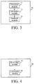
- FIG. 3 shows a structural diagram of an apparatus 30 used in a UE of a large scale antenna system according to an embodiment of the present invention.
- FIG. 4 shows a structural diagram of an apparatus 40 used in a base station device of a large scale antenna system according to an embodiment of the present invention.
- the apparatus 30 is usually configured in a UE.
- the apparatus 30 includes a detection module 31, a calculation module 32, and a feedback module 33.
- the apparatus 40 is usually configured in a base station device.
- the apparatus 40 includes a receiving module 41 and a calculation module 42.
- the detection module 31 is configured to detect a downlink channel.
- the calculation module 32 is configured to determine, according to a multipath propagation model from the detected downlink channel (matrix), a channel response of a first number of strong propagation paths, where the channel response of each strong propagation path is determined as a matrix related to the following time-varying parameters: an arrival direction, time to arrive, and a path amplitude.
- the channel response of each strong propagation path is, for example, the expression form at the right side of the equation in formula (1), but is not limited thereto.
- the feedback module 33 is configured to feed back the first number and indication information of the time-varying parameters of the first number of strong propagation paths.
- the "first number” (the number of strong propagation paths) is represented as K d , and all the propagation paths are sequenced in descending order of amplitudes, that is,
- the UE feeds back the indication information of the time-varying parameters of K d strong propagation paths.
- the number K d of the strong propagation paths is less than the total number K of propagation paths of the multipath channel, and therefore the feedback payload can be reduced.
- the feedback module 33 feeds back ⁇ ⁇ k , ⁇ k , ⁇ k
- k 1 ⁇ K d ⁇ .
- the change of the path amplitude with time is faster than the change of the arrival direction and time to arrive with time, and therefore, the feedback module 33 feeds back ⁇ ⁇ k , ⁇ k
- k 1 ⁇ K d ⁇ in a first average period which is longer, and feeds back ⁇ ⁇ k
- k 1 ⁇ K d ⁇ in a second average period which is shorter.
- feedback modes of different periods are applicable to the time-varying feature of the channel parameters, thereby further saving the feedback payload.
- the feedback module 33 feeds back ⁇ ⁇ k
- k 1 ⁇ K d ⁇ in the first average period which is longer, and feeds back ⁇ ⁇ k , ⁇ k
- k 1 ⁇ K d ⁇ in the second average period which is shorter.
- the feedback module 33 feeds back ⁇ ⁇ k
- k 1 ⁇ K d ⁇ , ⁇ ⁇ k
- k 1 ⁇ K d ⁇ , and ⁇ ⁇ k
- k 1 ⁇ K d ⁇ in three different average periods.
- the receiving module 41 is configured to receive a first number and indication information of time-varying parameters of the first number of strong propagation paths, where the first number and the indication information are fed back by a UE, and the time-varying parameters include: an arrival direction, time to arrive, and a path amplitude.
- the receiving module 41 receives ⁇ ⁇ k
- k 1 ⁇ K d ⁇ , ⁇ ⁇ k
- k 1 ⁇ K d ⁇ , and ⁇ ⁇ k
- k 1 ⁇ K d ⁇ that are fed back by the UE, but is not limited thereto.
- the calculation module 42 is configured to determine a downlink channel response according to the received indication information of the time-varying parameters of the first number of strong propagation paths.
- the reconstruction of the downlink channel may be represented by the foregoing formula (4), but is not limited thereto.
- the channel response on one sub-band may be regarded as flat; only the channel coefficient allocated to the UE needs to be fed back and reported, and it is unnecessary to report channel coefficients of the entire bandwidth.
- the foregoing formula (1) may be re-written as the foregoing formula (5).
- a channel vector of the j th subcarrier can be represented as the foregoing formula (6).
- the whole bandwidth is divided into multiple sub-bands, and the channel response in each sub-band can be regarded as flat.
- the average channel vector of the s th sub-band is represented as h ⁇ s , and h ⁇ s can be calculated by using the foregoing formula (7), where J S represents the number of subcarriers in one sub-band, J(S) represents a set of subcarriers in the s th sub-band, and b ⁇ k,s represents the joint mean value of the time to arrive and path amplitude in the sub-band. If only the s th sub-band is allocated to the UE, the UE only feeds back and reports h ⁇ s to the base station device, and it is unnecessary to report the complete channel matrix H.
- a first number of strong propagation paths are determined as K d propagation paths with a maximum module of the joint mean value b ⁇ k,s or a maximum norm.
- all the propagation paths are sequenced in descending order of modules of joint mean values of time to arrive and path amplitudes, that is,
- the UE only needs to feed back the indication information of the time-varying parameters of K d strong propagation paths.
- the number K d of the strong propagation paths is less than the total number K of propagation paths of the multipath channel, and therefore the feedback payload can be reduced.
- the feedback module 33 feeds back ⁇ ⁇ k , b ⁇ k , s
- k 1 ⁇ K d ⁇ .
- the change of the joint mean value of the path amplitude with time is faster than the change of the arrival direction with time, and therefore, the feedback module 33 feeds back ⁇ ⁇ k
- k 1 ⁇ K d ⁇ in a first average period which is longer, and feeds back ⁇ b ⁇ k,s
- K 1 ⁇ Kd ⁇ in a second average period which is shorter.
- feedback modes of different periods are applicable to the time-varying feature of the channel parameters, thereby further saving the feedback payload.
- the receiving module 41 receives ⁇ ⁇ k
- the reconstruction of the downlink channel by the calculation module 42 may be represented by the foregoing formula (8), but is not limited thereto.
- any one of the modules above can be implemented by multiple entity modules or functional modules, and the functions of multiple modules above can also be integrated on one entity module or implemented by a functional module.
Landscapes
- Engineering & Computer Science (AREA)
- Computer Networks & Wireless Communication (AREA)
- Signal Processing (AREA)
- Mobile Radio Communication Systems (AREA)
- Radio Transmission System (AREA)
Abstract
Description
- The present invention generally relates to a mobile communications technology, and more particularly, to a multiple user multiple input multiple output (MU MIMO) transmission technology.
- In a Frequency Division Duplexing (FDD) system, downlink closed loop MIMO processing requires channel state information (CSI) feedback from a user equipment (UE). With the increase of the number of base station antennas, the feedback payload also increases, which makes it more and more difficult for the CSI feedback payload to meet the requirement of an actual application. In a large scale antenna system, a base station device may be equipped with and use 100 or more antennas. In this case, the conventional short-time CSI feedback is impractical for the actual application. In another aspect, the decrease of the total transmit power of the large scale antenna system mostly relies on precise CSI, which also makes the CSI feedback essential in the large scale antenna system.
- A main object of the present invention is to provide a CSI feedback solution used in a MIMO system, to solve the defects in the prior art. Recent multi-antenna measurement and researches indicate that in most cases, a radio cannel in a large scale antenna system is sparse, and the channel capacity of the radio channel is merely determined by some free degree (which is far less than the number of antennas).
- An embodiment provides a method used in a UE of a large scale antenna system, including: detecting a downlink channel; determining, according to a multipath propagation model, a channel response of a first number of strong propagation paths, where the channel response of each propagation path is determined as a matrix related to the following time-varying parameters: an arrival direction, time to arrive, and a path amplitude; and feeding back the first number and indication information of the time-varying parameters of the first number of strong propagation paths.
- In an embodiment of the foregoing method, indication information of the arrival direction and time to arrival is fed back based on a first average period, indication information of the path amplitude is fed back based on a second average period, and the first average period is longer than the second average period.
- In an embodiment of the foregoing method, the downlink channel includes a sub-band, where the indication information of the time-varying parameters of the first number of strong propagation paths includes: indication information of the arrival direction, and indication information of a joint mean value of the time to arrive and the path amplitude in the sub-band.
- In an embodiment of the foregoing method, the indication information of the arrival direction is fed back based on a first average period, the indication information of the joint mean value of the time to arrive and path amplitude in the sub-band is fed back based on a second average period, and the first average period is longer than the second average period.
- Another embodiment provides a method used in a base station device of a large scale antenna system, including: receiving a first number and indication information of time-varying parameters of the first number of strong propagation paths, where the first number and the indication information are fed back by a UE, and the time-varying parameters include: an arrival direction, time to arrive, and a path amplitude; and determining a downlink channel response according to the received indication information of the time-varying parameters of the first number of strong propagation paths.
- In an embodiment of the foregoing method, the downlink channel includes a sub-band, where the indication information of the time-varying parameters of the first number of strong propagation paths includes: indication information of the arrival direction, and indication information of a joint mean value of the time to arrive and the path amplitude in the sub-band.
- A still another embodiment provides an apparatus used in a UE of a large scale antenna system, including: a detection module, configured to detect a downlink channel; a calculation module, configured to determine, according to a multipath propagation model, a channel response of a first number of strong propagation paths, where the channel response of each propagation path is determined as a matrix related to the following time-varying parameters: an arrival direction, time to arrive, and a path amplitude; and a feedback module, configured to feed back the first number and indication information of the time-varying parameters of the first number of strong propagation paths.
- In an embodiment of the foregoing apparatus, the feedback module is configured to feed back indication information of the arrival direction and time to arrival based on a first average period, and feed back indication information of the path amplitude based on a second average period, where the first average period is longer than the second average period.
- In an embodiment of the foregoing apparatus, the downlink channel includes a sub-band, where the indication information of the time-varying parameters of the first number of strong propagation paths includes: indication information of the arrival direction, and indication information of a joint mean value of the time to arrive and the path amplitude in the sub-band.
- In an embodiment of the foregoing apparatus, the feedback module is configured to feed back the indication information of the arrival direction based on a first average period, and feed back the indication information of the joint mean value of the time to arrive and the path amplitude in the sub-band based on a second average period, where the first average period is longer than the second average period.
- A UE includes the foregoing apparatus.
- Another embodiment provides an apparatus used in a base station device of a large scale antenna system, including: a receiving module, configured to receive a first number and indication information of time-varying parameters of the first number of strong propagation paths, where the first number and the indication information are fed back by a UE, and the time-varying parameters include: an arrival direction, time to arrive, and a path amplitude; and a calculation module, configured to determine a downlink channel response according to the received indication information of the time-varying parameters of the first number of strong propagation paths.
- In an embodiment of the foregoing apparatus, the downlink channel includes a sub-band, where the indication information of the time-varying parameters of the first number of strong propagation paths includes: indication information of the arrival direction, and indication information of a joint mean value of the time to arrive and the path amplitude in the sub-band.
- Abase station device includes the foregoing apparatus.
- The technical features and advantages of the present invention are described above so that the detailed description of the present invention below is easier to understand. Other features and advantages of the present invention will be described in the following, to form the subject of the claims of the present invention. A person skilled in the art can understand that the disclosed concepts and embodiments can be easily modified, or a basis of a structure or procedure used for implementing the same objective as the present invention can be designed. A person skilled in the art should also understand that, such equivalent structures still fall within the spirit and scope of the appended claims.
- With reference to the accompanying drawings, the detailed description of the preferred embodiments of the present invention is easier to understand. The present invention is described by using examples, but is not limited to the accompanying drawings; similar sings in the accompanying drawings refer to similar elements.
-
FIG. 1 shows a flowchart of a method used in a UE of a large scale antenna system according to an embodiment of the present invention; -
FIG. 2 shows a flowchart of a method used in a base station device of a large scale antenna system according to an embodiment of the present invention; -
FIG. 3 shows a structural diagram of an apparatus used in a UE of a large scale antenna system according to an embodiment of the present invention; and -
FIG. 4 shows a structural diagram of an apparatus used in a base station device of a large scale antenna system according to an embodiment of the present invention. - The detailed description of the accompanying drawings is intended to serve as the description of the current preferred embodiment of the present invention, but is not intended to represent the only form for implementing the present invention. It should be understood that identical or equivalent functions can be implemented by different embodiments included in the spirit and scope of the present invention.
- A person skilled in the art can understand that, the means and functions described herein can be implemented by software functions that combine a program control microprocessor and a general computer and/or implemented by using an application specific integrated circuit (ASIC). It should be further understood that, although the present invention is described in the form of methods and apparatuses, the present invention can also be embodied as a computer program product and a system that includes a computer processor and a memory connected to the processor. The memory is encoded by using one or more programs that can implement the functions disclosed herein.
- A person skilled in the art should understand that, the base station or base station device herein is, for example, a Node B or an evolved Node N (eNB) in an LTE system or an LTB-A system, but is not limited thereto. The technical solution of the present invention is not limited to applications in the LTE system or the LTE-A system.
- A base station is configured with a linear antenna array of N transmit antennas, and uses an Orthogonal Frequency Division Multiplexing (OFDM) system with the number of subcarriers being NFFT. A radio multipath channel is formed by K propagation paths, and for each propagation path, time to arrive (ToA) is τk, an arrival direction is θk, and a complex amplitude is βk (k = 1 to K). A frequency domain of the channel response thus can be represented as follows:


-
FIG. 1 shows a flowchart of amethod 10 used in a UE of a large scale antenna system according to an embodiment of the present invention.FIG. 2 shows a flowchart of amethod 20 used in a base station device in a large scale antenna system according to an embodiment of the present invention. As shown in the figures, themethod 10 includesSteps method 20 includesSteps - In
Step 11, a UE detects a downlink channel. - In
Step 12, the UE determines, according to a multipath propagation model from the detected downlink channel (matrix), a channel response of a first number of strong propagation paths, where the channel response of each propagation path is determined as a matrix related to the following time-varying parameters: an arrival direction, time to arrive, and a path amplitude. The channel response of each propagation path is, for example, the expression form at the right side of the equation in formula (1), but is not limited thereto. - A first number of strong propagation paths are usually selected by using the following manners.
- In the first manner, the "first number" is not predetermined. First, a propagation path with a maximum amplitude, that is, a propagation path whose corresponding βk has a maximum module, is determined. Then, all propagation paths, ratios of amplitudes of which to the maximum propagation path amplitude are not less than (or greater than) a predetermined value, are determined, where the predetermined value is, for example, any value between 0.1 and 0.2, but is not limited thereto. The propagation paths, the ratios of the amplitudes of which to the maximum propagation path amplitude are not less than the predetermined value (including the propagation path with the maximum amplitude value), are the first number of strong propagation paths. In an extreme case, the "first number" may be 1, that is, there is only one strong propagation path, namely, the propagation path with the maximum amplitude value.
- In the second manner, the "first number" is determined in advance. The "first number" of propagation paths with the maximum amplitude are strong propagation paths. This manner can control the operation volume and the feedback information volume in advance.
- In
Step 13, the UE feeds back the first number and indication information of the time-varying parameters of the first number of strong propagation paths. - Generally, the "first number" (the number of strong propagation paths) is represented as Kd, and all the propagation paths are sequenced in descending order of amplitudes, that is, |β 1|≥|β 2|Λ≥|βk |. The UE feeds back the indication information of the time-varying parameters of Kd strong propagation paths. The number Kd of the strong propagation paths is less than the total number K of propagation paths of the multipath channel, and therefore the feedback payload can be reduced.
- In an embodiment, the UE feeds back {τk ,θk ,βk |k=1∼Kd }. The change of the path amplitude with time is faster than the change of the arrival direction and time to arrive with time, and therefore, the UE feeds back {τk ,θk |k=1∼Kd } in a first average period which is longer, and feeds back {βk |k=1∼Kd } in a second average period which is shorter. In this way, feedback modes of different periods are applicable to the time-varying feature of the channel parameters, thereby further saving the feedback payload.
- In another embodiment, the UE feeds back {θ k |k=1∼Kd } in the first average period which is longer, and feeds back {τ k ,βk |k=1∼Kd } in the second average period which is shorter. In still another embodiment, the UE feeds back {θk |k=1∼Kd }, {τk |k=1∼Kd }, and {βk |k=1∼Kd } in three different average periods.
- In
Step 21, the base station device receives the first number and the indication information of the time-varying parameters of the first number of strong propagation paths, where the first number and the indication information are fed back by the UE, and the time-varying parameters include: an arrival direction, time to arrive, and a path amplitude. For example, the arrival direction, time to arrive, and path amplitude are {θk |k=1∼Kd }, {τk |k=1∼Kd }, and {βk |k=1∼Kd } that are fed back by the UE, but are not limited thereto. - In
Step 22, the base station device determines a downlink channel response according to the received indication information of the time-varying parameters of the first number of strong propagation paths. The reconstruction of the downlink channel may be represented by the following formula (4), but is not limited thereto.
- In some cases, several or only one sub-band is allocated to the UE. The channel response on one sub-band may be regarded as flat; only the channel coefficient allocated to the UE needs to be fed back and reported, and it is unnecessary to report channel coefficients of the entire bandwidth. The foregoing formula (1) can be re-written as:


- The whole bandwidth is divided into multiple sub-bands, and the channel response in each sub-band can be regarded as flat. An average channel vector of the sth sub-band is represented as h̃ s , and h̃ s is calculated according to the following formula:

- JS represents the number of subcarriers in one sub-band, J(s) represents a set of subcarriers in the sth sub-band, and
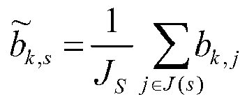
- Similarly, a first number of strong propagation paths are determined as Kd propagation paths with a maximum module of the joint mean value b̃ k,s or a maximum norm. Generally, all propagation paths are sequenced in descending order of modules of the joint mean values of time to arrive and path amplitudes, that is, |b̃ 1,s |≥|b̃ 2,s |≥Λ≥|b̃ k,s |, and the UE only needs to feed back indication information of the time-varying parameters of Kd strong propagation paths. The number Kd of the strong propagation paths is less than the total number K of propagation paths of the multipath channel, and therefore the feedback payload can be reduced.
- In an embodiment, the UE feeds back {θk ,b̃ k,s |k=1∼Kd }. The change of the joint mean value of the path amplitude with time is faster than the change of the arrival direction with time, and therefore, the UE feeds back {θk |k=1∼Kd } in a first average period which is longer, and feeds back {b̃k , s |k=1∼Kd } in a second average period which is shorter. In this way, feedback modes of different periods are applicable to the time-varying feature of the channel parameters, thereby further saving the feedback payload.
- Correspondingly, the base station device receives {θk |k=1∼Kd } and {b̃ k,s |k=1∼Kd } that are fed back by the UE.
- In
Step 22, the base station device reconstructs the downlink channel by using, for example, the formula (8) below, but is not limited thereto:
-
FIG. 3 shows a structural diagram of anapparatus 30 used in a UE of a large scale antenna system according to an embodiment of the present invention.FIG. 4 shows a structural diagram of anapparatus 40 used in a base station device of a large scale antenna system according to an embodiment of the present invention. Theapparatus 30 is usually configured in a UE. As shown inFIG. 3 , theapparatus 30 includes adetection module 31, acalculation module 32, and afeedback module 33. Theapparatus 40 is usually configured in a base station device. As shown inFIG. 4 , theapparatus 40 includes a receivingmodule 41 and acalculation module 42. - The
detection module 31 is configured to detect a downlink channel. - The
calculation module 32 is configured to determine, according to a multipath propagation model from the detected downlink channel (matrix), a channel response of a first number of strong propagation paths, where the channel response of each strong propagation path is determined as a matrix related to the following time-varying parameters: an arrival direction, time to arrive, and a path amplitude. The channel response of each strong propagation path is, for example, the expression form at the right side of the equation in formula (1), but is not limited thereto. - Two manners for determining the first number of strong propagation paths are described in the foregoing, and are not repeated herein.
- The
feedback module 33 is configured to feed back the first number and indication information of the time-varying parameters of the first number of strong propagation paths. - Generally, the "first number" (the number of strong propagation paths) is represented as Kd, and all the propagation paths are sequenced in descending order of amplitudes, that is, |≥|β 2|≥Λ≥|βk |. The UE feeds back the indication information of the time-varying parameters of Kd strong propagation paths. The number Kd of the strong propagation paths is less than the total number K of propagation paths of the multipath channel, and therefore the feedback payload can be reduced.
- In an embodiment, the
feedback module 33 feeds back {τk ,θk ,βk |k=1∼Kd }. The change of the path amplitude with time is faster than the change of the arrival direction and time to arrive with time, and therefore, thefeedback module 33 feeds back {τk ,θk |k=1∼Kd } in a first average period which is longer, and feeds back {βk |k=1∼Kd } in a second average period which is shorter. In this way, feedback modes of different periods are applicable to the time-varying feature of the channel parameters, thereby further saving the feedback payload. - In another embodiment, the
feedback module 33 feeds back {θk |k=1∼Kd } in the first average period which is longer, and feeds back {τk ,βk |k=1∼Kd } in the second average period which is shorter. In still another embodiment, thefeedback module 33 feeds back {θk |k=1∼Kd }, {τk |k=1∼Kd }, and {βk |k=1∼Kd } in three different average periods. - The receiving
module 41 is configured to receive a first number and indication information of time-varying parameters of the first number of strong propagation paths, where the first number and the indication information are fed back by a UE, and the time-varying parameters include: an arrival direction, time to arrive, and a path amplitude. For example, the receivingmodule 41 receives {θk |k=1∼Kd }, {τk |k=1∼Kd }, and {βk |k=1∼Kd } that are fed back by the UE, but is not limited thereto. - The
calculation module 42 is configured to determine a downlink channel response according to the received indication information of the time-varying parameters of the first number of strong propagation paths. The reconstruction of the downlink channel may be represented by the foregoing formula (4), but is not limited thereto. - In some cases, several or only one sub-band is allocated to the UE. The channel response on one sub-band may be regarded as flat; only the channel coefficient allocated to the UE needs to be fed back and reported, and it is unnecessary to report channel coefficients of the entire bandwidth. The foregoing formula (1) may be re-written as the foregoing formula (5). A channel vector of the jth subcarrier can be represented as the foregoing formula (6). The whole bandwidth is divided into multiple sub-bands, and the channel response in each sub-band can be regarded as flat. The average channel vector of the sth sub-band is represented as h̃ s , and h̃ s can be calculated by using the foregoing formula (7), where JS represents the number of subcarriers in one sub-band, J(S) represents a set of subcarriers in the sth sub-band, and b̃k,s represents the joint mean value of the time to arrive and path amplitude in the sub-band. If only the sth sub-band is allocated to the UE, the UE only feeds back and reports h̃ s to the base station device, and it is unnecessary to report the complete channel matrix H.
- Similarly, a first number of strong propagation paths are determined as Kd propagation paths with a maximum module of the joint mean value b̃k,s or a maximum norm. Generally, all the propagation paths are sequenced in descending order of modules of joint mean values of time to arrive and path amplitudes, that is, |b̃ 1,s |≥|b̃ 2,s |≥Λ≥|b k,s |. The UE only needs to feed back the indication information of the time-varying parameters of Kd strong propagation paths. The number Kd of the strong propagation paths is less than the total number K of propagation paths of the multipath channel, and therefore the feedback payload can be reduced.
- In an embodiment, the
feedback module 33 feeds back {θk ,b̃ k,s |k=1~Kd }. The change of the joint mean value of the path amplitude with time is faster than the change of the arrival direction with time, and therefore, thefeedback module 33 feeds back {θk |k=1∼Kd } in a first average period which is longer, and feeds back {b̃k,s |K=1∼Kd} in a second average period which is shorter. In this way, feedback modes of different periods are applicable to the time-varying feature of the channel parameters, thereby further saving the feedback payload. - Correspondingly, the receiving
module 41 receives {θk |k=1∼K d } and {bkos 1 k=1~ Ka that are fed back by the UE. The reconstruction of the downlink channel by thecalculation module 42 may be represented by the foregoing formula (8), but is not limited thereto. - A person skilled in the art should understand that, the function of any one of the modules above can be implemented by multiple entity modules or functional modules, and the functions of multiple modules above can also be integrated on one entity module or implemented by a functional module.
- Although different embodiments of the present invention are described above, the present invention is not limited to these embodiments. The ordinal numbers such as "first" and "second" in the claims are merely provided for the purpose of distinguishing, and does not mean that corresponding components have any specific sequence or connection relationship. The technical feature only appearing in some claims or embodiments does not mean that the technical feature cannot be combined with other features in other claims or embodiments to implement a new beneficial technical solution. Modifications, alterations, transformations, replacements, and equivalences within the spirit and scope of the present invention described in the claims are obvious to a person skilled in the art.
Claims (14)
- method used in a user equipment (UE) of a large scale antenna system, comprising:detecting a downlink channel;determining, according to a multipath propagation model, a channel response of a first number of strong propagation paths, wherein the channel response of each propagation path is determined as a matrix related to the following time-varying parameters: an arrival direction, time to arrive, and a path amplitude; andfeeding back the first number and indication information of the time-varying parameters of the first number of strong propagation paths.
- The method according to claim 1, wherein indication information of the arrival direction and time to arrival is fed back based on a first average period, indication information of the path amplitude is fed back based on a second average period, and the first average period is longer than the second average period.
- The method according to claim 1, wherein the downlink channel comprises a sub-band, and the indication information of the time-varying parameters of the first number of strong propagation paths comprises: indication information of the arrival direction, and indication information of a joint mean value of the time to arrive and the path amplitude in the sub-band.
- The method according to claim 3, wherein the indication information of the arrival direction is fed back based on a first average period, the indication information of the joint mean value of the time to arrive and the path amplitude in the sub-band is fed back based on a second average period, and the first average period is longer than the second average period.
- A method used in a base station device of a large scale antenna system, comprising:receiving a first number and indication information of time-varying parameters of the first number of strong propagation paths, wherein the first number and the indication information are fed back by a user equipment (UE), and the time-varying parameters comprise: an arrival direction, time to arrive, and a path amplitude; anddetermining a downlink channel response according to the received indication information of the time-varying parameters of the first number of strong propagation paths.
- The method according to claim 5, wherein the downlink channel comprises a sub-band, and the indication information of the time-varying parameters of the first number of strong propagation paths comprises: indication information of the arrival direction, and indication information of a joint mean value of the time to arrive and the path amplitude in the sub-band.
- An apparatus used in a user equipment (UE) of a large scale antenna system, comprising:a detection module, configured to detect a downlink channel;a calculation module, configured to determine, according to a multipath propagation model, a channel response of a first number of strong propagation paths, wherein the channel response of each propagation path is determined as a matrix related to the following time-varying parameters: an arrival direction, time to arrive, and a path amplitude; anda feedback module, configured to feed back the first number and indication information of the time-varying parameters of the first number of strong propagation paths.
- The apparatus according to claim 7, wherein the feedback module is configured to feed back indication information of the arrival direction and time to arrival based on a first average period, and feed back indication information of the path amplitude based on a second average period, wherein the first average period is longer than the second average period.
- The apparatus according to claim 7, wherein the downlink channel comprises a sub-band, and the indication information of the time-varying parameters of the first number of strong propagation paths comprises: indication information of the arrival direction, and indication information of a joint mean value of the time to arrive and the path amplitude in the sub-band.
- The apparatus according to claim 9, wherein the feedback module is configured to feed back the indication information of the arrival direction based on a first average period, and feed back the indication information of the joint mean value of the time to arrive and path amplitude in the sub-band based on a second average period, wherein the first average period is longer than the second average period.
- An apparatus used in a base station device of a large scale antenna system, comprising:a receiving module, configured to receive a first number and indication information of time-varying parameters of the first number of strong propagation paths, wherein the first number and the indication information are fed back by a user equipment (UE), and the time-varying parameters comprise: an arrival direction, time to arrive, and a path amplitude; anda calculation module, configured to determine a downlink channel response according to the received indication information of the time-varying parameters of the first number of strong propagation paths.
- The apparatus according to claim 11, wherein the downlink channel comprises a sub-band, and the indication information of the time-varying parameters of the first number of strong propagation paths comprises: indication information of the arrival direction, and indication information of a joint mean value of the time to arrive and the path amplitude in the sub-band.
- A user equipment (UE), comprising the apparatus according to any one of claims 7 to 10.
- A base station device, comprising the apparatus according to any one of claims 11 to 12.
Applications Claiming Priority (1)
| Application Number | Priority Date | Filing Date | Title |
|---|---|---|---|
| PCT/CN2013/000633 WO2014190452A1 (en) | 2013-05-29 | 2013-05-29 | Csi feedback method and device in large-scale antenna system |
Publications (3)
| Publication Number | Publication Date |
|---|---|
| EP3007366A1 true EP3007366A1 (en) | 2016-04-13 |
| EP3007366A4 EP3007366A4 (en) | 2017-01-11 |
| EP3007366B1 EP3007366B1 (en) | 2020-10-28 |
Family
ID=51987824
Family Applications (1)
| Application Number | Title | Priority Date | Filing Date |
|---|---|---|---|
| EP13885992.1A Not-in-force EP3007366B1 (en) | 2013-05-29 | 2013-05-29 | Csi feedback method and device in large-scale antenna system |
Country Status (6)
| Country | Link |
|---|---|
| US (1) | US10038487B2 (en) |
| EP (1) | EP3007366B1 (en) |
| JP (1) | JP6386032B2 (en) |
| CN (1) | CN105308882B (en) |
| TW (1) | TWI514806B (en) |
| WO (1) | WO2014190452A1 (en) |
Families Citing this family (7)
| Publication number | Priority date | Publication date | Assignee | Title |
|---|---|---|---|---|
| CN107786250B (en) * | 2016-08-23 | 2021-04-09 | 华为技术有限公司 | Feedback method and device for channel state information |
| CN107359914B (en) * | 2017-07-03 | 2020-05-22 | 中国人民解放军理工大学 | Channel state feedback method for MU-MIMO network based on multipath information |
| CN109412663B (en) * | 2017-08-16 | 2020-11-13 | 上海诺基亚贝尔股份有限公司 | Method, apparatus, and computer readable medium for MIMO communication |
| CN112583501B (en) * | 2019-09-30 | 2023-09-22 | 华为技术有限公司 | Channel measurement method and communication device |
| CN110890931B (en) * | 2019-11-11 | 2021-08-03 | 杭州电子科技大学 | An Uplink Time-varying Channel Prediction Method Based on Improved Prony Method |
| CN113315723B (en) * | 2020-02-27 | 2023-06-27 | 维沃移动通信有限公司 | Time delay reporting method, terminal equipment and network equipment |
| CN111901259B (en) * | 2020-05-18 | 2024-12-24 | 中兴通讯股份有限公司 | Downlink channel state information estimation method, device, equipment and storage medium |
Family Cites Families (11)
| Publication number | Priority date | Publication date | Assignee | Title |
|---|---|---|---|---|
| US6795392B1 (en) * | 2000-03-27 | 2004-09-21 | At&T Corp. | Clustered OFDM with channel estimation |
| JP2003060558A (en) | 2001-08-14 | 2003-02-28 | Matsushita Electric Ind Co Ltd | Communication terminal device and base station device |
| CN1841985A (en) | 2005-03-30 | 2006-10-04 | 松下电器产业株式会社 | Finite Feedback Method for Multiple Antenna Systems |
| EP2139124B1 (en) | 2008-06-24 | 2014-03-19 | Alcatel Lucent | A method for allocation of parameters for radio transmission in a wireless communication network using channel feedback compression, network elements and a wireless communication network therefor |
| US8249204B2 (en) * | 2008-07-11 | 2012-08-21 | Industrial Technology Research Institute | Apparatus and method for channel state information feedback |
| JP5134487B2 (en) | 2008-10-07 | 2013-01-30 | 株式会社光電製作所 | Wireless signal measuring device, channel sounder |
| JP5199935B2 (en) | 2009-03-27 | 2013-05-15 | 株式会社エヌ・ティ・ティ・ドコモ | Spatio-temporal channel simulator |
| JP5175247B2 (en) | 2009-06-30 | 2013-04-03 | 株式会社エヌ・ティ・ティ・ドコモ | Radio wave propagation parameter estimation device, radio wave propagation parameter estimation method |
| WO2011146606A1 (en) * | 2010-05-19 | 2011-11-24 | Interdigital Patent Holdings, Inc. | Method and apparatus for compressing channel state information based on path location information |
| CN102377527B (en) * | 2010-08-09 | 2014-12-24 | 上海贝尔股份有限公司 | Method and device for decreasing multi-cell feedback overhead |
| CN102457321B (en) * | 2010-10-26 | 2014-06-04 | 上海贝尔股份有限公司 | Method for predicting down link SINR (Signal-to-Interference and Noise Ratio) in wireless communication system, equipment and base station |
-
2013
- 2013-05-29 US US14/892,320 patent/US10038487B2/en active Active
- 2013-05-29 CN CN201380075746.2A patent/CN105308882B/en active Active
- 2013-05-29 WO PCT/CN2013/000633 patent/WO2014190452A1/en not_active Ceased
- 2013-05-29 JP JP2016515585A patent/JP6386032B2/en not_active Expired - Fee Related
- 2013-05-29 EP EP13885992.1A patent/EP3007366B1/en not_active Not-in-force
-
2014
- 2014-05-09 TW TW103116616A patent/TWI514806B/en not_active IP Right Cessation
Also Published As
| Publication number | Publication date |
|---|---|
| WO2014190452A1 (en) | 2014-12-04 |
| EP3007366A4 (en) | 2017-01-11 |
| CN105308882A (en) | 2016-02-03 |
| US10038487B2 (en) | 2018-07-31 |
| CN105308882B (en) | 2018-07-03 |
| JP6386032B2 (en) | 2018-09-05 |
| EP3007366B1 (en) | 2020-10-28 |
| JP2016524403A (en) | 2016-08-12 |
| TWI514806B (en) | 2015-12-21 |
| US20160112108A1 (en) | 2016-04-21 |
| TW201503624A (en) | 2015-01-16 |
Similar Documents
| Publication | Publication Date | Title |
|---|---|---|
| EP3007366B1 (en) | Csi feedback method and device in large-scale antenna system | |
| US8599810B2 (en) | Method, equipment and system for implementing coordinated multi-point transmission | |
| EP2469729B1 (en) | Method and apparatus for keeping the precoding channel coherency in a communication network | |
| US8165533B2 (en) | Apparatus and method for beamforming based on generalized eigen-analysis in multiple input multiple output wireless communication system | |
| US10171267B2 (en) | Uplink pilot sequence allocation method in massive MIMO system and base station thereof | |
| US20160373175A1 (en) | Systems and Methods for Adapting a Codebook for Use with Multiple Antenna Configurations | |
| US20120034874A1 (en) | Apparatuses and/or methods of interference mitigation and/or rate improvement via uncoordinated beamforming in heterogeneous networks | |
| EP3038270A1 (en) | Method for performing multiple access in wireless OFDM cellular systems over multipath wireless channels considering both space and frequency domains, base station and computer programs thereof | |
| US9722745B2 (en) | Method and base station for coordinated multi point data transmission | |
| US10298297B2 (en) | Method and device for feeding back downlink channel feedback information, and method and device for user pairing | |
| US9954695B2 (en) | Channel measurement method for large-scale antennas, and user terminal | |
| CN103475397A (en) | Three-dimensional wave beam forming method, communication station and mobile station | |
| EP3557795B1 (en) | Channel state information reporting method, base station and user equipment | |
| CN101686500B (en) | Method and user terminal for determining correlation parameters, and signal forming method and base station | |
| CN105991175A (en) | Method and device for sending and receiving pilot signals | |
| EP2850742B1 (en) | Calculating and reporting channel characteristics | |
| WO2017219739A1 (en) | Method and device for determining beamforming vector | |
| EP2992622B1 (en) | Cqdebqqk feedback methqd and apparatus for multiple-antenna channel in mimq system | |
| CN103873125B (en) | The launching technique and equipment of downstream signal in a kind of multiaerial system | |
| CN101540746A (en) | Method and device for quantizing time and frequency channel and corresponding mobile communication terminal and corresponding mobile communication system | |
| EP3157216B1 (en) | Method and device for acquiring downlink data in large-scale mimo system | |
| CN102487549B (en) | Method and device for scheduling user equipment in MIMO (multiple-input multiple-output) wireless communication system | |
| US20150326284A1 (en) | System and Method for Multiple-Input Multiple-Output Communication | |
| CN106161290A (en) | A kind of inter-stream interference computational methods, device and communication system | |
| CN103096349B (en) | A kind of method and apparatus being dynamically determined USTP value |
Legal Events
| Date | Code | Title | Description |
|---|---|---|---|
| PUAI | Public reference made under article 153(3) epc to a published international application that has entered the european phase |
Free format text: ORIGINAL CODE: 0009012 |
|
| 17P | Request for examination filed |
Effective date: 20160104 |
|
| AK | Designated contracting states |
Kind code of ref document: A1 Designated state(s): AL AT BE BG CH CY CZ DE DK EE ES FI FR GB GR HR HU IE IS IT LI LT LU LV MC MK MT NL NO PL PT RO RS SE SI SK SM TR |
|
| AX | Request for extension of the european patent |
Extension state: BA ME |
|
| DAX | Request for extension of the european patent (deleted) | ||
| A4 | Supplementary search report drawn up and despatched |
Effective date: 20161212 |
|
| RIC1 | Information provided on ipc code assigned before grant |
Ipc: H04B 7/04 20170101AFI20161206BHEP |
|
| STAA | Information on the status of an ep patent application or granted ep patent |
Free format text: STATUS: EXAMINATION IS IN PROGRESS |
|
| 17Q | First examination report despatched |
Effective date: 20180130 |
|
| RAP1 | Party data changed (applicant data changed or rights of an application transferred) |
Owner name: ALCATEL LUCENT |
|
| GRAP | Despatch of communication of intention to grant a patent |
Free format text: ORIGINAL CODE: EPIDOSNIGR1 |
|
| STAA | Information on the status of an ep patent application or granted ep patent |
Free format text: STATUS: GRANT OF PATENT IS INTENDED |
|
| INTG | Intention to grant announced |
Effective date: 20200514 |
|
| GRAS | Grant fee paid |
Free format text: ORIGINAL CODE: EPIDOSNIGR3 |
|
| GRAA | (expected) grant |
Free format text: ORIGINAL CODE: 0009210 |
|
| STAA | Information on the status of an ep patent application or granted ep patent |
Free format text: STATUS: THE PATENT HAS BEEN GRANTED |
|
| AK | Designated contracting states |
Kind code of ref document: B1 Designated state(s): AL AT BE BG CH CY CZ DE DK EE ES FI FR GB GR HR HU IE IS IT LI LT LU LV MC MK MT NL NO PL PT RO RS SE SI SK SM TR |
|
| REG | Reference to a national code |
Ref country code: GB Ref legal event code: FG4D |
|
| REG | Reference to a national code |
Ref country code: CH Ref legal event code: EP |
|
| REG | Reference to a national code |
Ref country code: AT Ref legal event code: REF Ref document number: 1329284 Country of ref document: AT Kind code of ref document: T Effective date: 20201115 |
|
| REG | Reference to a national code |
Ref country code: DE Ref legal event code: R096 Ref document number: 602013073693 Country of ref document: DE |
|
| REG | Reference to a national code |
Ref country code: IE Ref legal event code: FG4D |
|
| REG | Reference to a national code |
Ref country code: AT Ref legal event code: MK05 Ref document number: 1329284 Country of ref document: AT Kind code of ref document: T Effective date: 20201028 |
|
| REG | Reference to a national code |
Ref country code: NL Ref legal event code: MP Effective date: 20201028 |
|
| PG25 | Lapsed in a contracting state [announced via postgrant information from national office to epo] |
Ref country code: RS Free format text: LAPSE BECAUSE OF FAILURE TO SUBMIT A TRANSLATION OF THE DESCRIPTION OR TO PAY THE FEE WITHIN THE PRESCRIBED TIME-LIMIT Effective date: 20201028 Ref country code: FI Free format text: LAPSE BECAUSE OF FAILURE TO SUBMIT A TRANSLATION OF THE DESCRIPTION OR TO PAY THE FEE WITHIN THE PRESCRIBED TIME-LIMIT Effective date: 20201028 Ref country code: NO Free format text: LAPSE BECAUSE OF FAILURE TO SUBMIT A TRANSLATION OF THE DESCRIPTION OR TO PAY THE FEE WITHIN THE PRESCRIBED TIME-LIMIT Effective date: 20210128 Ref country code: PT Free format text: LAPSE BECAUSE OF FAILURE TO SUBMIT A TRANSLATION OF THE DESCRIPTION OR TO PAY THE FEE WITHIN THE PRESCRIBED TIME-LIMIT Effective date: 20210301 Ref country code: NL Free format text: LAPSE BECAUSE OF FAILURE TO SUBMIT A TRANSLATION OF THE DESCRIPTION OR TO PAY THE FEE WITHIN THE PRESCRIBED TIME-LIMIT Effective date: 20201028 Ref country code: GR Free format text: LAPSE BECAUSE OF FAILURE TO SUBMIT A TRANSLATION OF THE DESCRIPTION OR TO PAY THE FEE WITHIN THE PRESCRIBED TIME-LIMIT Effective date: 20210129 |
|
| REG | Reference to a national code |
Ref country code: LT Ref legal event code: MG4D |
|
| PG25 | Lapsed in a contracting state [announced via postgrant information from national office to epo] |
Ref country code: ES Free format text: LAPSE BECAUSE OF FAILURE TO SUBMIT A TRANSLATION OF THE DESCRIPTION OR TO PAY THE FEE WITHIN THE PRESCRIBED TIME-LIMIT Effective date: 20201028 Ref country code: AT Free format text: LAPSE BECAUSE OF FAILURE TO SUBMIT A TRANSLATION OF THE DESCRIPTION OR TO PAY THE FEE WITHIN THE PRESCRIBED TIME-LIMIT Effective date: 20201028 Ref country code: BG Free format text: LAPSE BECAUSE OF FAILURE TO SUBMIT A TRANSLATION OF THE DESCRIPTION OR TO PAY THE FEE WITHIN THE PRESCRIBED TIME-LIMIT Effective date: 20210128 Ref country code: IS Free format text: LAPSE BECAUSE OF FAILURE TO SUBMIT A TRANSLATION OF THE DESCRIPTION OR TO PAY THE FEE WITHIN THE PRESCRIBED TIME-LIMIT Effective date: 20210228 Ref country code: LV Free format text: LAPSE BECAUSE OF FAILURE TO SUBMIT A TRANSLATION OF THE DESCRIPTION OR TO PAY THE FEE WITHIN THE PRESCRIBED TIME-LIMIT Effective date: 20201028 Ref country code: SE Free format text: LAPSE BECAUSE OF FAILURE TO SUBMIT A TRANSLATION OF THE DESCRIPTION OR TO PAY THE FEE WITHIN THE PRESCRIBED TIME-LIMIT Effective date: 20201028 Ref country code: PL Free format text: LAPSE BECAUSE OF FAILURE TO SUBMIT A TRANSLATION OF THE DESCRIPTION OR TO PAY THE FEE WITHIN THE PRESCRIBED TIME-LIMIT Effective date: 20201028 |
|
| PG25 | Lapsed in a contracting state [announced via postgrant information from national office to epo] |
Ref country code: HR Free format text: LAPSE BECAUSE OF FAILURE TO SUBMIT A TRANSLATION OF THE DESCRIPTION OR TO PAY THE FEE WITHIN THE PRESCRIBED TIME-LIMIT Effective date: 20201028 |
|
| REG | Reference to a national code |
Ref country code: DE Ref legal event code: R097 Ref document number: 602013073693 Country of ref document: DE |
|
| PG25 | Lapsed in a contracting state [announced via postgrant information from national office to epo] |
Ref country code: SM Free format text: LAPSE BECAUSE OF FAILURE TO SUBMIT A TRANSLATION OF THE DESCRIPTION OR TO PAY THE FEE WITHIN THE PRESCRIBED TIME-LIMIT Effective date: 20201028 Ref country code: CZ Free format text: LAPSE BECAUSE OF FAILURE TO SUBMIT A TRANSLATION OF THE DESCRIPTION OR TO PAY THE FEE WITHIN THE PRESCRIBED TIME-LIMIT Effective date: 20201028 Ref country code: EE Free format text: LAPSE BECAUSE OF FAILURE TO SUBMIT A TRANSLATION OF THE DESCRIPTION OR TO PAY THE FEE WITHIN THE PRESCRIBED TIME-LIMIT Effective date: 20201028 Ref country code: LT Free format text: LAPSE BECAUSE OF FAILURE TO SUBMIT A TRANSLATION OF THE DESCRIPTION OR TO PAY THE FEE WITHIN THE PRESCRIBED TIME-LIMIT Effective date: 20201028 Ref country code: RO Free format text: LAPSE BECAUSE OF FAILURE TO SUBMIT A TRANSLATION OF THE DESCRIPTION OR TO PAY THE FEE WITHIN THE PRESCRIBED TIME-LIMIT Effective date: 20201028 Ref country code: SK Free format text: LAPSE BECAUSE OF FAILURE TO SUBMIT A TRANSLATION OF THE DESCRIPTION OR TO PAY THE FEE WITHIN THE PRESCRIBED TIME-LIMIT Effective date: 20201028 |
|
| PGFP | Annual fee paid to national office [announced via postgrant information from national office to epo] |
Ref country code: DE Payment date: 20210505 Year of fee payment: 9 Ref country code: FR Payment date: 20210412 Year of fee payment: 9 |
|
| PG25 | Lapsed in a contracting state [announced via postgrant information from national office to epo] |
Ref country code: DK Free format text: LAPSE BECAUSE OF FAILURE TO SUBMIT A TRANSLATION OF THE DESCRIPTION OR TO PAY THE FEE WITHIN THE PRESCRIBED TIME-LIMIT Effective date: 20201028 |
|
| PGFP | Annual fee paid to national office [announced via postgrant information from national office to epo] |
Ref country code: GB Payment date: 20210505 Year of fee payment: 9 |
|
| PLBE | No opposition filed within time limit |
Free format text: ORIGINAL CODE: 0009261 |
|
| STAA | Information on the status of an ep patent application or granted ep patent |
Free format text: STATUS: NO OPPOSITION FILED WITHIN TIME LIMIT |
|
| 26N | No opposition filed |
Effective date: 20210729 |
|
| PG25 | Lapsed in a contracting state [announced via postgrant information from national office to epo] |
Ref country code: IT Free format text: LAPSE BECAUSE OF FAILURE TO SUBMIT A TRANSLATION OF THE DESCRIPTION OR TO PAY THE FEE WITHIN THE PRESCRIBED TIME-LIMIT Effective date: 20201028 Ref country code: AL Free format text: LAPSE BECAUSE OF FAILURE TO SUBMIT A TRANSLATION OF THE DESCRIPTION OR TO PAY THE FEE WITHIN THE PRESCRIBED TIME-LIMIT Effective date: 20201028 |
|
| PG25 | Lapsed in a contracting state [announced via postgrant information from national office to epo] |
Ref country code: SI Free format text: LAPSE BECAUSE OF FAILURE TO SUBMIT A TRANSLATION OF THE DESCRIPTION OR TO PAY THE FEE WITHIN THE PRESCRIBED TIME-LIMIT Effective date: 20201028 |
|
| REG | Reference to a national code |
Ref country code: CH Ref legal event code: PL |
|
| PG25 | Lapsed in a contracting state [announced via postgrant information from national office to epo] |
Ref country code: CH Free format text: LAPSE BECAUSE OF NON-PAYMENT OF DUE FEES Effective date: 20210531 Ref country code: LU Free format text: LAPSE BECAUSE OF NON-PAYMENT OF DUE FEES Effective date: 20210529 Ref country code: MC Free format text: LAPSE BECAUSE OF FAILURE TO SUBMIT A TRANSLATION OF THE DESCRIPTION OR TO PAY THE FEE WITHIN THE PRESCRIBED TIME-LIMIT Effective date: 20201028 Ref country code: LI Free format text: LAPSE BECAUSE OF NON-PAYMENT OF DUE FEES Effective date: 20210531 |
|
| REG | Reference to a national code |
Ref country code: BE Ref legal event code: MM Effective date: 20210531 |
|
| PG25 | Lapsed in a contracting state [announced via postgrant information from national office to epo] |
Ref country code: IE Free format text: LAPSE BECAUSE OF NON-PAYMENT OF DUE FEES Effective date: 20210529 |
|
| PG25 | Lapsed in a contracting state [announced via postgrant information from national office to epo] |
Ref country code: IS Free format text: LAPSE BECAUSE OF FAILURE TO SUBMIT A TRANSLATION OF THE DESCRIPTION OR TO PAY THE FEE WITHIN THE PRESCRIBED TIME-LIMIT Effective date: 20210228 |
|
| PG25 | Lapsed in a contracting state [announced via postgrant information from national office to epo] |
Ref country code: BE Free format text: LAPSE BECAUSE OF NON-PAYMENT OF DUE FEES Effective date: 20210531 |
|
| REG | Reference to a national code |
Ref country code: DE Ref legal event code: R119 Ref document number: 602013073693 Country of ref document: DE |
|
| GBPC | Gb: european patent ceased through non-payment of renewal fee |
Effective date: 20220529 |
|
| PG25 | Lapsed in a contracting state [announced via postgrant information from national office to epo] |
Ref country code: FR Free format text: LAPSE BECAUSE OF NON-PAYMENT OF DUE FEES Effective date: 20220531 |
|
| PG25 | Lapsed in a contracting state [announced via postgrant information from national office to epo] |
Ref country code: HU Free format text: LAPSE BECAUSE OF FAILURE TO SUBMIT A TRANSLATION OF THE DESCRIPTION OR TO PAY THE FEE WITHIN THE PRESCRIBED TIME-LIMIT; INVALID AB INITIO Effective date: 20130529 Ref country code: GB Free format text: LAPSE BECAUSE OF NON-PAYMENT OF DUE FEES Effective date: 20220529 Ref country code: DE Free format text: LAPSE BECAUSE OF NON-PAYMENT OF DUE FEES Effective date: 20221201 |
|
| PG25 | Lapsed in a contracting state [announced via postgrant information from national office to epo] |
Ref country code: CY Free format text: LAPSE BECAUSE OF FAILURE TO SUBMIT A TRANSLATION OF THE DESCRIPTION OR TO PAY THE FEE WITHIN THE PRESCRIBED TIME-LIMIT Effective date: 20201028 |
|
| PG25 | Lapsed in a contracting state [announced via postgrant information from national office to epo] |
Ref country code: MK Free format text: LAPSE BECAUSE OF FAILURE TO SUBMIT A TRANSLATION OF THE DESCRIPTION OR TO PAY THE FEE WITHIN THE PRESCRIBED TIME-LIMIT Effective date: 20201028 |
|
| PG25 | Lapsed in a contracting state [announced via postgrant information from national office to epo] |
Ref country code: MT Free format text: LAPSE BECAUSE OF FAILURE TO SUBMIT A TRANSLATION OF THE DESCRIPTION OR TO PAY THE FEE WITHIN THE PRESCRIBED TIME-LIMIT Effective date: 20201028 |
|
| PG25 | Lapsed in a contracting state [announced via postgrant information from national office to epo] |
Ref country code: TR Free format text: LAPSE BECAUSE OF FAILURE TO SUBMIT A TRANSLATION OF THE DESCRIPTION OR TO PAY THE FEE WITHIN THE PRESCRIBED TIME-LIMIT Effective date: 20201028 |