EP3006932A1 - Transverse-magnetization magnetic system for intra-pipe defectoscope - Google Patents
Transverse-magnetization magnetic system for intra-pipe defectoscope Download PDFInfo
- Publication number
- EP3006932A1 EP3006932A1 EP14893694.1A EP14893694A EP3006932A1 EP 3006932 A1 EP3006932 A1 EP 3006932A1 EP 14893694 A EP14893694 A EP 14893694A EP 3006932 A1 EP3006932 A1 EP 3006932A1
- Authority
- EP
- European Patent Office
- Prior art keywords
- magnetic
- modules
- main
- belts
- magnetic modules
- Prior art date
- Legal status (The legal status is an assumption and is not a legal conclusion. Google has not performed a legal analysis and makes no representation as to the accuracy of the status listed.)
- Granted
Links
- 230000005291 magnetic effect Effects 0.000 title claims abstract description 108
- 230000005415 magnetization Effects 0.000 claims abstract description 13
- 239000004020 conductor Substances 0.000 claims abstract description 7
- 230000004907 flux Effects 0.000 claims abstract description 3
- 239000003302 ferromagnetic material Substances 0.000 claims description 4
- 230000006698 induction Effects 0.000 claims description 2
- 238000001514 detection method Methods 0.000 abstract description 4
- 230000003247 decreasing effect Effects 0.000 abstract description 3
- 230000000694 effects Effects 0.000 abstract description 3
- 238000009659 non-destructive testing Methods 0.000 abstract description 3
- 239000000463 material Substances 0.000 description 3
- 230000001788 irregular Effects 0.000 description 2
- 238000005452 bending Methods 0.000 description 1
- 230000005294 ferromagnetic effect Effects 0.000 description 1
- 230000035945 sensitivity Effects 0.000 description 1
Images


Classifications
-
- G—PHYSICS
- G01—MEASURING; TESTING
- G01N—INVESTIGATING OR ANALYSING MATERIALS BY DETERMINING THEIR CHEMICAL OR PHYSICAL PROPERTIES
- G01N27/00—Investigating or analysing materials by the use of electric, electrochemical, or magnetic means
- G01N27/72—Investigating or analysing materials by the use of electric, electrochemical, or magnetic means by investigating magnetic variables
- G01N27/82—Investigating or analysing materials by the use of electric, electrochemical, or magnetic means by investigating magnetic variables for investigating the presence of flaws
- G01N27/83—Investigating or analysing materials by the use of electric, electrochemical, or magnetic means by investigating magnetic variables for investigating the presence of flaws by investigating stray magnetic fields
- G01N27/87—Investigating or analysing materials by the use of electric, electrochemical, or magnetic means by investigating magnetic variables for investigating the presence of flaws by investigating stray magnetic fields using probes
-
- F—MECHANICAL ENGINEERING; LIGHTING; HEATING; WEAPONS; BLASTING
- F17—STORING OR DISTRIBUTING GASES OR LIQUIDS
- F17D—PIPE-LINE SYSTEMS; PIPE-LINES
- F17D5/00—Protection or supervision of installations
Definitions
- This utility model relates to the field of magnetic flaw detection, namely to devices used for non-destructive testing of pipelines, and, in particular, to a magnetic system of an in-pipe flaw detector.
- An in-pipe flaw detector is known ( RU Patent No. 2225977 , publ. 27.05.2003, IPC G01M3/08, F17D5/00, G01N27/72), which sensors are arranged in respective holders, each holder being fixed in the flaw detector housing with the use of a pair of arms capable of rotating in a plane crossing the axis of symmetry of the magnetic flaw detector.
- the invention enables to improve the flaw detector capacity of passing through long, curved, narrowed regions in a pipeline and to reduce a volume of data not suitable for identifying flaws in a pipeline wall; but, due to irregular distribution of a magnetic field in circumferential and longitudinal directions, this flaw detector provides errors while determining flaw dimensions.
- An in-pipe flaw detector is known ( RU Patent No. 2248498 , publ. 29.10.2003, IPC F17D5/00, G01M3/00), which non-destructive testing sensors are arranged in respective sensor holders, each sensor holder being fixed in the flaw detector housing with the use of at least two arms. On the arm or the sensor holder at the flaw detector nose portion, one or more elements are arranged that are made capable of bending toward the tail portion in a plane passing through the axis of symmetry of the flaw detector.
- this flaw detector enables to improve the flaw detector capacity of passing through long, curved, narrowed regions in a pipeline and to reduce a volume of data not suitable for identifying flaws in a pipeline wall; but, due to irregular distribution of a magnetic field in circumferential and longitudinal directions, this flaw detector provides errors while determining flaw dimensions.
- the closest prototype for the claimed utility model is a magnetic measuring system with transverse magnetization for an in-pipe flaw detector ( RU Patent No. 109863 , publ. 27.05.11, IPC G01N27/83), which consists of identical magnetic modules for transverse magnetization in the form of two annular belts arranged symmetrically relative to the central axis of a hollow cylindrical base, one after the other, on spring-loaded articulated arms coupled to the hollow cylindrical base, meanwhile one or more additional permanent magnets in the form of a rectangular parallelepiped are arranged in the interpolar space of each magnetic module for the purpose of improving uniformity of magnetic field distribution.
- the technical effect of the claimed utility model consists in reducing flaw detection errors due to mutual influence of the magnetic module main belts, thus improving uniformity of magnetic field distribution in circumferential and longitudinal directions.
- the magnetic system for transverse magnetization having fixed magnetic modules and designed for an in-pipe flaw detector consists of two main and four additional magnetic module belts arranged on two magnetic conductors connected by a non-magnetic insert.
- Each magnetic module consists of permanent magnets and ferromagnetic elements transferring a magnetic flux to the pipeline wall.
- the adjacent magnetic modules in a belt have opposite directions of a magnetic field in the interpolar space.
- Sensors which register any change in magnetic induction, as caused by a change in the pipeline wall thickness, are arranged between magnetic poles along the length of a pipeline circumference.
- the additional belts of magnetic modules are arranged at the edges of the main belts of the magnetic modules; two additional belts of magnetic modules are arranged between the main belts of magnetic modules and serve for compensating mutual influence of a magnetic field generated by the main belts of magnetic modules and for decreasing non-symmetry of a magnetic field which symmetry is caused by close location of the main belts of magnetic modules.
- Each additional belt of magnetic modules is angularly offset relative to a main magnetic belt by an angle ⁇ 90° for the purpose of correcting non-symmetry of a magnetic field.
- a pipeline material is magnetized to the condition of technical saturation, since with an increase in magnetization intrinsic noises of a pipeline material as well as sensitivity of the flaw detector measuring system to a pipeline material are reduced.
- the magnetic system for transverse magnetization having fixed magnetic modules for an in-pipe flaw detector may be made of a single section and of a plurality of sections, and in this case it may comprise two or more main belts of magnetic modules and four or more additional belts of magnetic modules that are arranged on two or more magnetic conductors, and in this case a cardan joint may be substituted for the non-magnetic insert.
- Fig. 1 shows a general view of the magnetic system for transverse magnetization having fixed magnetic modules and designed for an in-pipe flaw detector.
- Fig. 1 The following designations are used in Fig. 1 :
- Fig. 2 shows cross-sectional views of the main magnetic modules used in the magnetic system for transverse magnetization having fixed magnetic modules and designed for an in-pipe flaw detector.
- Fig. 3 shows cross-sectional views of the additional magnetic modules used in the magnetic system for transverse magnetization having fixed magnetic modules and designed for an in-pipe flaw detector.
- the magnetic system for transverse magnetization having fixed magnetic modules and designed for an in-pipe flaw detector consists of two main belts of magnetic modules 1 ( Fig. 1 ) and four additional belts of magnetic modules 2 ( Fig. 1 ), which are arranged on two magnetic conductors 3 ( Fig. 2 and Fig. 3 ) connected with a non-magnetic insert 4 ( Fig. 1 ).
- the magnetic modules 1 and 2 consist of permanent magnets 5 ( Fig. 2 and Fig. 3 ) and elements 6 made of a ferromagnetic material ( Fig. 2 and Fig. 3 ).
Landscapes
- Chemical & Material Sciences (AREA)
- Engineering & Computer Science (AREA)
- Life Sciences & Earth Sciences (AREA)
- Analytical Chemistry (AREA)
- Chemical Kinetics & Catalysis (AREA)
- Electrochemistry (AREA)
- Physics & Mathematics (AREA)
- Health & Medical Sciences (AREA)
- Mechanical Engineering (AREA)
- General Engineering & Computer Science (AREA)
- Biochemistry (AREA)
- General Health & Medical Sciences (AREA)
- General Physics & Mathematics (AREA)
- Immunology (AREA)
- Pathology (AREA)
- Investigating Or Analyzing Materials By The Use Of Magnetic Means (AREA)
Abstract
Description
- This utility model relates to the field of magnetic flaw detection, namely to devices used for non-destructive testing of pipelines, and, in particular, to a magnetic system of an in-pipe flaw detector.
- An in-pipe flaw detector is known (
RU Patent No. 2225977 - An in-pipe flaw detector is known (
RU Patent No. 2248498 - The closest prototype for the claimed utility model is a magnetic measuring system with transverse magnetization for an in-pipe flaw detector (
RU Patent No. 109863 - The technical effect of the claimed utility model consists in reducing flaw detection errors due to mutual influence of the magnetic module main belts, thus improving uniformity of magnetic field distribution in circumferential and longitudinal directions.
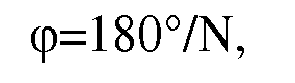
- The technical effect of the claimed utility model is achieved due to the fact that the magnetic system for transverse magnetization having fixed magnetic modules and designed for an in-pipe flaw detector consists of two main and four additional magnetic module belts arranged on two magnetic conductors connected by a non-magnetic insert. Each magnetic module consists of permanent magnets and ferromagnetic elements transferring a magnetic flux to the pipeline wall. The adjacent magnetic modules in a belt have opposite directions of a magnetic field in the interpolar space. The main poles of the magnetic modules are angularly offset relative to each other by the angle ϕ:
- The additional belts of magnetic modules are arranged at the edges of the main belts of the magnetic modules; two additional belts of magnetic modules are arranged between the main belts of magnetic modules and serve for compensating mutual influence of a magnetic field generated by the main belts of magnetic modules and for decreasing non-symmetry of a magnetic field which symmetry is caused by close location of the main belts of magnetic modules. Each additional belt of magnetic modules is angularly offset relative to a main magnetic belt by an angle α<90° for the purpose of correcting non-symmetry of a magnetic field.
- In order to reduce errors, a pipeline material is magnetized to the condition of technical saturation, since with an increase in magnetization intrinsic noises of a pipeline material as well as sensitivity of the flaw detector measuring system to a pipeline material are reduced.
- In a development of the utility model, the magnetic system for transverse magnetization having fixed magnetic modules for an in-pipe flaw detector may be made of a single section and of a plurality of sections, and in this case it may comprise two or more main belts of magnetic modules and four or more additional belts of magnetic modules that are arranged on two or more magnetic conductors, and in this case a cardan joint may be substituted for the non-magnetic insert.
- As a result, flaw detection errors are reduced due to decrease in mutual influence of the main belts of magnetic modules and improvement of magnetic field distribution in circumferential and longitudinal directions.
-
Fig. 1 shows a general view of the magnetic system for transverse magnetization having fixed magnetic modules and designed for an in-pipe flaw detector. - The following designations are used in
Fig. 1 : - 1.- main belt of magnetic modules;
- 2.- additional belt of magnetic modules;
- 4.- non-magnetic insert.
-
Fig. 2 shows cross-sectional views of the main magnetic modules used in the magnetic system for transverse magnetization having fixed magnetic modules and designed for an in-pipe flaw detector. - The following designations are used in
Fig. 2 : - 3.- magnetic conductor;
- 5.- permanent magnet;
- 6.- elements made of a ferromagnetic material.
-
Fig. 3 shows cross-sectional views of the additional magnetic modules used in the magnetic system for transverse magnetization having fixed magnetic modules and designed for an in-pipe flaw detector. - The following designations are used in
Fig. 3 : - 3- magnetic conductor;
- 5- permanent magnet;
- 6- elements made of a ferromagnetic material.
- The magnetic system for transverse magnetization having fixed magnetic modules and designed for an in-pipe flaw detector (
Fig. 1 ) consists of two main belts of magnetic modules 1 (Fig. 1 ) and four additional belts of magnetic modules 2 (Fig. 1 ), which are arranged on two magnetic conductors 3 (Fig. 2 andFig. 3 ) connected with a non-magnetic insert 4 (Fig. 1 ). Themagnetic modules 1 and 2 (Fig. 1 ) consist of permanent magnets 5 (Fig. 2 andFig. 3 ) andelements 6 made of a ferromagnetic material (Fig. 2 andFig. 3 ).
Claims (3)
- A magnetic system for transverse magnetization having fixed magnetic modules and designed for an in-pipe flaw detector, consisting of two main and four additional belts of magnetic modules that are arranged on two magnetic conductors connected with a non-magnetic insert, each magnetic module consisting of permanent magnets and elements made of a ferromagnetic material, which modules transfer a magnetic flux into a pipeline wall, and adjacent magnetic modules in a belt have opposite directions of a magnetic field in an interpolar space.
- The magnetic system for transverse magnetization having fixed magnetic modules and designed for an in-pipe flaw detector according to Claim 1, characterized in that the main poles of the magnetic modules are angularly offset relative to each other, and sensors registering any change in magnetic induction, as caused by a change in a pipeline wall thickness, are arranged along the pipeline circumference.
- The magnetic system for transverse magnetization having fixed magnetic modules and designed for an in-pipe flaw detector according to Claim 1, characterized in that additional belts of magnetic modules are arranged at the edges of the main belts of magnetic modules, two additional belts of magnetic modules being arranged between the main belts of magnetic modules, and each additional belt of magnetic modules being angularly offset relative to a main magnetic belt by an angle α<90°.
Applications Claiming Priority (2)
| Application Number | Priority Date | Filing Date | Title |
|---|---|---|---|
| RU2014126248 | 2014-06-30 | ||
| PCT/RU2014/000858 WO2016003314A1 (en) | 2014-06-30 | 2014-11-12 | Transverse-magnetization magnetic system for intra-pipe defectoscope |
Publications (3)
| Publication Number | Publication Date |
|---|---|
| EP3006932A1 true EP3006932A1 (en) | 2016-04-13 |
| EP3006932A4 EP3006932A4 (en) | 2017-04-26 |
| EP3006932B1 EP3006932B1 (en) | 2018-05-09 |
Family
ID=55019703
Family Applications (1)
| Application Number | Title | Priority Date | Filing Date |
|---|---|---|---|
| EP14893694.1A Not-in-force EP3006932B1 (en) | 2014-06-30 | 2014-11-12 | Transverse-magnetization magnetic system for intra-pipe defectoscope |
Country Status (5)
| Country | Link |
|---|---|
| EP (1) | EP3006932B1 (en) |
| BR (1) | BR112016027451B1 (en) |
| EA (1) | EA029806B1 (en) |
| MX (1) | MX375748B (en) |
| WO (1) | WO2016003314A1 (en) |
Cited By (1)
| Publication number | Priority date | Publication date | Assignee | Title |
|---|---|---|---|---|
| EP4484352A1 (en) | 2023-06-30 | 2025-01-01 | Akademia Gorniczo-Hutnicza im. Stanislawa Staszica w Krakowie | Position control system for magnetic diagnostics of steel ropes and a measuring head |
Family Cites Families (4)
| Publication number | Priority date | Publication date | Assignee | Title |
|---|---|---|---|---|
| RU2225977C1 (en) * | 2003-05-27 | 2004-03-20 | ЗАО "Нефтегазкомплектсервис" | Intratube flaw detector |
| RU2248498C1 (en) * | 2003-10-29 | 2005-03-20 | ЗАО "Нефтегазкомплектсервис" | Flaw detector for testing pipe from inside |
| GB2470054B (en) * | 2009-05-07 | 2013-08-07 | Pii Ltd | Magnetising assembly |
| RU109863U1 (en) * | 2011-05-27 | 2011-10-27 | Открытое акционерное общество Акционерная компания по транспорту нефти "Транснефть" | MAGNETIC SYSTEM OF AN IN-TUBE DEFECTOSCOPE WITH TRANSVERSE MAGNETIZATION |
-
2014
- 2014-11-12 MX MX2016014553A patent/MX375748B/en active IP Right Grant
- 2014-11-12 EP EP14893694.1A patent/EP3006932B1/en not_active Not-in-force
- 2014-11-12 EA EA201592156A patent/EA029806B1/en not_active IP Right Cessation
- 2014-11-12 BR BR112016027451-2A patent/BR112016027451B1/en not_active IP Right Cessation
- 2014-11-12 WO PCT/RU2014/000858 patent/WO2016003314A1/en not_active Ceased
Cited By (1)
| Publication number | Priority date | Publication date | Assignee | Title |
|---|---|---|---|---|
| EP4484352A1 (en) | 2023-06-30 | 2025-01-01 | Akademia Gorniczo-Hutnicza im. Stanislawa Staszica w Krakowie | Position control system for magnetic diagnostics of steel ropes and a measuring head |
Also Published As
| Publication number | Publication date |
|---|---|
| MX2016014553A (en) | 2017-06-30 |
| MX375748B (en) | 2025-03-06 |
| WO2016003314A1 (en) | 2016-01-07 |
| EP3006932B1 (en) | 2018-05-09 |
| EA201592156A1 (en) | 2016-04-29 |
| BR112016027451A2 (en) | 2021-01-12 |
| BR112016027451B1 (en) | 2021-05-04 |
| EP3006932A4 (en) | 2017-04-26 |
| EA029806B1 (en) | 2018-05-31 |
Similar Documents
| Publication | Publication Date | Title |
|---|---|---|
| CN103487503B (en) | A kind of rotating magnetic field eddy current probe | |
| EP2940464B1 (en) | Apparatus and method for detecting inner defects of steel plate | |
| CN104297281B (en) | An arc-shaped single-sided nuclear magnetic resonance sensor | |
| CN107850571A (en) | Defect measurement method, defect measurement device, and inspection probe | |
| EP2249355B1 (en) | Magnetising assembly | |
| EP2778621A8 (en) | Magnetic Angle Position Sensor | |
| US10473730B2 (en) | Defect detection device enabling easy removal of magnetic impurities | |
| KR20150048141A (en) | Eddy current flaw detection probe and eddy current flaw inspection apparatus | |
| MX2015009010A (en) | Magnetic measuring system for a flaw detector having longitudinal magnetization. | |
| CN106290552B (en) | A steel plate magnetic flux leakage detection device based on rotating magnetization field | |
| CN103868984A (en) | Device for detecting damage to inner surface of overground high-pressure manifold | |
| CN102879461B (en) | Non-directional electromagnetic detecting sensor based on crosslinking differential detecting principle | |
| EP3006932B1 (en) | Transverse-magnetization magnetic system for intra-pipe defectoscope | |
| JP6483069B2 (en) | Sensor device including carrier | |
| RU117186U1 (en) | MULTI-SECTION IN-TUBE MAGNETIC DEFECTOSCOPE | |
| BR102012029637B1 (en) | set of magnets for a magnetic core flow meter | |
| CN203758959U (en) | Inner surface flaw detecting device of ground high pressure manifold | |
| CN104874538B (en) | Bending-mode magnetostriction sensor | |
| RU147368U1 (en) | MAGNETIC TRANSVERSE MAGNETIZATION SYSTEM WITH FIXED MAGNETIC MODULES FOR AN IN-TUBE DEFECTOSCOPE | |
| CN110763755A (en) | Evaluation method capable of rapidly evaluating crack defect direction of metal material | |
| HRP20141231T1 (en) | Measuring instrument, in particular a voltage tester | |
| CN105874329B (en) | Apparatus and method for detecting defects of steel sheet | |
| RU109863U1 (en) | MAGNETIC SYSTEM OF AN IN-TUBE DEFECTOSCOPE WITH TRANSVERSE MAGNETIZATION | |
| RU133933U1 (en) | MAGNETIC MEASURING SYSTEM FOR LONGITUDINAL DEFECTOSCOPE | |
| JP2016133459A (en) | Eddy current testing probe, Eddy current testing equipment |
Legal Events
| Date | Code | Title | Description |
|---|---|---|---|
| PUAI | Public reference made under article 153(3) epc to a published international application that has entered the european phase |
Free format text: ORIGINAL CODE: 0009012 |
|
| 17P | Request for examination filed |
Effective date: 20151209 |
|
| AK | Designated contracting states |
Kind code of ref document: A1 Designated state(s): AL AT BE BG CH CY CZ DE DK EE ES FI FR GB GR HR HU IE IS IT LI LT LU LV MC MK MT NL NO PL PT RO RS SE SI SK SM TR |
|
| AX | Request for extension of the european patent |
Extension state: BA ME |
|
| RAP1 | Party data changed (applicant data changed or rights of an application transferred) |
Owner name: JOINT, STOCK COMPANY "TRANSNEFT DIASCAN" Owner name: PUBLIC JOINT STOCK COMPANY "TRANSNEFT" |
|
| REG | Reference to a national code |
Ref country code: DE Ref legal event code: R079 Ref document number: 602014025415 Country of ref document: DE Free format text: PREVIOUS MAIN CLASS: G01N0027830000 Ipc: G01N0027870000 |
|
| A4 | Supplementary search report drawn up and despatched |
Effective date: 20170329 |
|
| RIC1 | Information provided on ipc code assigned before grant |
Ipc: G01N 27/87 20060101AFI20170323BHEP |
|
| DAX | Request for extension of the european patent (deleted) | ||
| GRAP | Despatch of communication of intention to grant a patent |
Free format text: ORIGINAL CODE: EPIDOSNIGR1 |
|
| STAA | Information on the status of an ep patent application or granted ep patent |
Free format text: STATUS: GRANT OF PATENT IS INTENDED |
|
| INTG | Intention to grant announced |
Effective date: 20180103 |
|
| GRAS | Grant fee paid |
Free format text: ORIGINAL CODE: EPIDOSNIGR3 |
|
| GRAA | (expected) grant |
Free format text: ORIGINAL CODE: 0009210 |
|
| STAA | Information on the status of an ep patent application or granted ep patent |
Free format text: STATUS: THE PATENT HAS BEEN GRANTED |
|
| AK | Designated contracting states |
Kind code of ref document: B1 Designated state(s): AL AT BE BG CH CY CZ DE DK EE ES FI FR GB GR HR HU IE IS IT LI LT LU LV MC MK MT NL NO PL PT RO RS SE SI SK SM TR |
|
| REG | Reference to a national code |
Ref country code: GB Ref legal event code: FG4D |
|
| REG | Reference to a national code |
Ref country code: CH Ref legal event code: EP Ref country code: AT Ref legal event code: REF Ref document number: 998036 Country of ref document: AT Kind code of ref document: T Effective date: 20180515 |
|
| REG | Reference to a national code |
Ref country code: IE Ref legal event code: FG4D |
|
| REG | Reference to a national code |
Ref country code: DE Ref legal event code: R096 Ref document number: 602014025415 Country of ref document: DE |
|
| REG | Reference to a national code |
Ref country code: NL Ref legal event code: FP |
|
| REG | Reference to a national code |
Ref country code: LT Ref legal event code: MG4D |
|
| REG | Reference to a national code |
Ref country code: CH Ref legal event code: NV Representative=s name: TROESCH SCHEIDEGGER WERNER AG, CH |
|
| PG25 | Lapsed in a contracting state [announced via postgrant information from national office to epo] |
Ref country code: NO Free format text: LAPSE BECAUSE OF FAILURE TO SUBMIT A TRANSLATION OF THE DESCRIPTION OR TO PAY THE FEE WITHIN THE PRESCRIBED TIME-LIMIT Effective date: 20180809 Ref country code: FI Free format text: LAPSE BECAUSE OF FAILURE TO SUBMIT A TRANSLATION OF THE DESCRIPTION OR TO PAY THE FEE WITHIN THE PRESCRIBED TIME-LIMIT Effective date: 20180509 Ref country code: LT Free format text: LAPSE BECAUSE OF FAILURE TO SUBMIT A TRANSLATION OF THE DESCRIPTION OR TO PAY THE FEE WITHIN THE PRESCRIBED TIME-LIMIT Effective date: 20180509 Ref country code: ES Free format text: LAPSE BECAUSE OF FAILURE TO SUBMIT A TRANSLATION OF THE DESCRIPTION OR TO PAY THE FEE WITHIN THE PRESCRIBED TIME-LIMIT Effective date: 20180509 Ref country code: SE Free format text: LAPSE BECAUSE OF FAILURE TO SUBMIT A TRANSLATION OF THE DESCRIPTION OR TO PAY THE FEE WITHIN THE PRESCRIBED TIME-LIMIT Effective date: 20180509 Ref country code: BG Free format text: LAPSE BECAUSE OF FAILURE TO SUBMIT A TRANSLATION OF THE DESCRIPTION OR TO PAY THE FEE WITHIN THE PRESCRIBED TIME-LIMIT Effective date: 20180809 |
|
| PG25 | Lapsed in a contracting state [announced via postgrant information from national office to epo] |
Ref country code: LV Free format text: LAPSE BECAUSE OF FAILURE TO SUBMIT A TRANSLATION OF THE DESCRIPTION OR TO PAY THE FEE WITHIN THE PRESCRIBED TIME-LIMIT Effective date: 20180509 Ref country code: RS Free format text: LAPSE BECAUSE OF FAILURE TO SUBMIT A TRANSLATION OF THE DESCRIPTION OR TO PAY THE FEE WITHIN THE PRESCRIBED TIME-LIMIT Effective date: 20180509 Ref country code: GR Free format text: LAPSE BECAUSE OF FAILURE TO SUBMIT A TRANSLATION OF THE DESCRIPTION OR TO PAY THE FEE WITHIN THE PRESCRIBED TIME-LIMIT Effective date: 20180810 Ref country code: HR Free format text: LAPSE BECAUSE OF FAILURE TO SUBMIT A TRANSLATION OF THE DESCRIPTION OR TO PAY THE FEE WITHIN THE PRESCRIBED TIME-LIMIT Effective date: 20180509 |
|
| REG | Reference to a national code |
Ref country code: AT Ref legal event code: MK05 Ref document number: 998036 Country of ref document: AT Kind code of ref document: T Effective date: 20180509 |
|
| PG25 | Lapsed in a contracting state [announced via postgrant information from national office to epo] |
Ref country code: DK Free format text: LAPSE BECAUSE OF FAILURE TO SUBMIT A TRANSLATION OF THE DESCRIPTION OR TO PAY THE FEE WITHIN THE PRESCRIBED TIME-LIMIT Effective date: 20180509 Ref country code: AT Free format text: LAPSE BECAUSE OF FAILURE TO SUBMIT A TRANSLATION OF THE DESCRIPTION OR TO PAY THE FEE WITHIN THE PRESCRIBED TIME-LIMIT Effective date: 20180509 Ref country code: PL Free format text: LAPSE BECAUSE OF FAILURE TO SUBMIT A TRANSLATION OF THE DESCRIPTION OR TO PAY THE FEE WITHIN THE PRESCRIBED TIME-LIMIT Effective date: 20180509 Ref country code: EE Free format text: LAPSE BECAUSE OF FAILURE TO SUBMIT A TRANSLATION OF THE DESCRIPTION OR TO PAY THE FEE WITHIN THE PRESCRIBED TIME-LIMIT Effective date: 20180509 Ref country code: SK Free format text: LAPSE BECAUSE OF FAILURE TO SUBMIT A TRANSLATION OF THE DESCRIPTION OR TO PAY THE FEE WITHIN THE PRESCRIBED TIME-LIMIT Effective date: 20180509 Ref country code: CZ Free format text: LAPSE BECAUSE OF FAILURE TO SUBMIT A TRANSLATION OF THE DESCRIPTION OR TO PAY THE FEE WITHIN THE PRESCRIBED TIME-LIMIT Effective date: 20180509 Ref country code: RO Free format text: LAPSE BECAUSE OF FAILURE TO SUBMIT A TRANSLATION OF THE DESCRIPTION OR TO PAY THE FEE WITHIN THE PRESCRIBED TIME-LIMIT Effective date: 20180509 |
|
| REG | Reference to a national code |
Ref country code: DE Ref legal event code: R097 Ref document number: 602014025415 Country of ref document: DE |
|
| PG25 | Lapsed in a contracting state [announced via postgrant information from national office to epo] |
Ref country code: IT Free format text: LAPSE BECAUSE OF FAILURE TO SUBMIT A TRANSLATION OF THE DESCRIPTION OR TO PAY THE FEE WITHIN THE PRESCRIBED TIME-LIMIT Effective date: 20180509 Ref country code: SM Free format text: LAPSE BECAUSE OF FAILURE TO SUBMIT A TRANSLATION OF THE DESCRIPTION OR TO PAY THE FEE WITHIN THE PRESCRIBED TIME-LIMIT Effective date: 20180509 |
|
| PLBE | No opposition filed within time limit |
Free format text: ORIGINAL CODE: 0009261 |
|
| STAA | Information on the status of an ep patent application or granted ep patent |
Free format text: STATUS: NO OPPOSITION FILED WITHIN TIME LIMIT |
|
| 26N | No opposition filed |
Effective date: 20190212 |
|
| PG25 | Lapsed in a contracting state [announced via postgrant information from national office to epo] |
Ref country code: SI Free format text: LAPSE BECAUSE OF FAILURE TO SUBMIT A TRANSLATION OF THE DESCRIPTION OR TO PAY THE FEE WITHIN THE PRESCRIBED TIME-LIMIT Effective date: 20180509 |
|
| PG25 | Lapsed in a contracting state [announced via postgrant information from national office to epo] |
Ref country code: LU Free format text: LAPSE BECAUSE OF NON-PAYMENT OF DUE FEES Effective date: 20181112 Ref country code: MC Free format text: LAPSE BECAUSE OF FAILURE TO SUBMIT A TRANSLATION OF THE DESCRIPTION OR TO PAY THE FEE WITHIN THE PRESCRIBED TIME-LIMIT Effective date: 20180509 |
|
| REG | Reference to a national code |
Ref country code: BE Ref legal event code: MM Effective date: 20181130 |
|
| REG | Reference to a national code |
Ref country code: IE Ref legal event code: MM4A |
|
| PG25 | Lapsed in a contracting state [announced via postgrant information from national office to epo] |
Ref country code: IE Free format text: LAPSE BECAUSE OF NON-PAYMENT OF DUE FEES Effective date: 20181112 |
|
| PG25 | Lapsed in a contracting state [announced via postgrant information from national office to epo] |
Ref country code: AL Free format text: LAPSE BECAUSE OF FAILURE TO SUBMIT A TRANSLATION OF THE DESCRIPTION OR TO PAY THE FEE WITHIN THE PRESCRIBED TIME-LIMIT Effective date: 20180509 Ref country code: BE Free format text: LAPSE BECAUSE OF NON-PAYMENT OF DUE FEES Effective date: 20181130 |
|
| PG25 | Lapsed in a contracting state [announced via postgrant information from national office to epo] |
Ref country code: MT Free format text: LAPSE BECAUSE OF NON-PAYMENT OF DUE FEES Effective date: 20181112 |
|
| PG25 | Lapsed in a contracting state [announced via postgrant information from national office to epo] |
Ref country code: TR Free format text: LAPSE BECAUSE OF FAILURE TO SUBMIT A TRANSLATION OF THE DESCRIPTION OR TO PAY THE FEE WITHIN THE PRESCRIBED TIME-LIMIT Effective date: 20180509 |
|
| PG25 | Lapsed in a contracting state [announced via postgrant information from national office to epo] |
Ref country code: PT Free format text: LAPSE BECAUSE OF FAILURE TO SUBMIT A TRANSLATION OF THE DESCRIPTION OR TO PAY THE FEE WITHIN THE PRESCRIBED TIME-LIMIT Effective date: 20180509 |
|
| PG25 | Lapsed in a contracting state [announced via postgrant information from national office to epo] |
Ref country code: MK Free format text: LAPSE BECAUSE OF NON-PAYMENT OF DUE FEES Effective date: 20180509 Ref country code: CY Free format text: LAPSE BECAUSE OF FAILURE TO SUBMIT A TRANSLATION OF THE DESCRIPTION OR TO PAY THE FEE WITHIN THE PRESCRIBED TIME-LIMIT Effective date: 20180509 Ref country code: HU Free format text: LAPSE BECAUSE OF FAILURE TO SUBMIT A TRANSLATION OF THE DESCRIPTION OR TO PAY THE FEE WITHIN THE PRESCRIBED TIME-LIMIT; INVALID AB INITIO Effective date: 20141112 |
|
| PG25 | Lapsed in a contracting state [announced via postgrant information from national office to epo] |
Ref country code: IS Free format text: LAPSE BECAUSE OF FAILURE TO SUBMIT A TRANSLATION OF THE DESCRIPTION OR TO PAY THE FEE WITHIN THE PRESCRIBED TIME-LIMIT Effective date: 20180909 |
|
| PGFP | Annual fee paid to national office [announced via postgrant information from national office to epo] |
Ref country code: FR Payment date: 20211110 Year of fee payment: 8 Ref country code: NL Payment date: 20211110 Year of fee payment: 8 Ref country code: GB Payment date: 20211110 Year of fee payment: 8 Ref country code: DE Payment date: 20210914 Year of fee payment: 8 |
|
| PGFP | Annual fee paid to national office [announced via postgrant information from national office to epo] |
Ref country code: CH Payment date: 20211110 Year of fee payment: 8 |
|
| REG | Reference to a national code |
Ref country code: DE Ref legal event code: R119 Ref document number: 602014025415 Country of ref document: DE |
|
| REG | Reference to a national code |
Ref country code: CH Ref legal event code: PL |
|
| REG | Reference to a national code |
Ref country code: NL Ref legal event code: MM Effective date: 20221201 |
|
| GBPC | Gb: european patent ceased through non-payment of renewal fee |
Effective date: 20221112 |
|
| PG25 | Lapsed in a contracting state [announced via postgrant information from national office to epo] |
Ref country code: LI Free format text: LAPSE BECAUSE OF NON-PAYMENT OF DUE FEES Effective date: 20221130 Ref country code: CH Free format text: LAPSE BECAUSE OF NON-PAYMENT OF DUE FEES Effective date: 20221130 |
|
| PG25 | Lapsed in a contracting state [announced via postgrant information from national office to epo] |
Ref country code: NL Free format text: LAPSE BECAUSE OF NON-PAYMENT OF DUE FEES Effective date: 20221201 |
|
| PG25 | Lapsed in a contracting state [announced via postgrant information from national office to epo] |
Ref country code: GB Free format text: LAPSE BECAUSE OF NON-PAYMENT OF DUE FEES Effective date: 20221112 Ref country code: DE Free format text: LAPSE BECAUSE OF NON-PAYMENT OF DUE FEES Effective date: 20230601 |
|
| PG25 | Lapsed in a contracting state [announced via postgrant information from national office to epo] |
Ref country code: FR Free format text: LAPSE BECAUSE OF NON-PAYMENT OF DUE FEES Effective date: 20221130 |