EP3006848B1 - Heat pump device - Google Patents
Heat pump device Download PDFInfo
- Publication number
- EP3006848B1 EP3006848B1 EP14801598.5A EP14801598A EP3006848B1 EP 3006848 B1 EP3006848 B1 EP 3006848B1 EP 14801598 A EP14801598 A EP 14801598A EP 3006848 B1 EP3006848 B1 EP 3006848B1
- Authority
- EP
- European Patent Office
- Prior art keywords
- vane
- cylinder
- compression
- operation mode
- electric motor
- Prior art date
- Legal status (The legal status is an assumption and is not a legal conclusion. Google has not performed a legal analysis and makes no representation as to the accuracy of the status listed.)
- Not-in-force
Links
Images


Classifications
-
- F—MECHANICAL ENGINEERING; LIGHTING; HEATING; WEAPONS; BLASTING
- F25—REFRIGERATION OR COOLING; COMBINED HEATING AND REFRIGERATION SYSTEMS; HEAT PUMP SYSTEMS; MANUFACTURE OR STORAGE OF ICE; LIQUEFACTION SOLIDIFICATION OF GASES
- F25B—REFRIGERATION MACHINES, PLANTS OR SYSTEMS; COMBINED HEATING AND REFRIGERATION SYSTEMS; HEAT PUMP SYSTEMS
- F25B30/00—Heat pumps
- F25B30/02—Heat pumps of the compression type
-
- F—MECHANICAL ENGINEERING; LIGHTING; HEATING; WEAPONS; BLASTING
- F04—POSITIVE - DISPLACEMENT MACHINES FOR LIQUIDS; PUMPS FOR LIQUIDS OR ELASTIC FLUIDS
- F04C—ROTARY-PISTON, OR OSCILLATING-PISTON, POSITIVE-DISPLACEMENT MACHINES FOR LIQUIDS; ROTARY-PISTON, OR OSCILLATING-PISTON, POSITIVE-DISPLACEMENT PUMPS
- F04C18/00—Rotary-piston pumps specially adapted for elastic fluids
- F04C18/30—Rotary-piston pumps specially adapted for elastic fluids having the characteristics covered by two or more of groups F04C18/02, F04C18/08, F04C18/22, F04C18/24, F04C18/48, or having the characteristics covered by one of these groups together with some other type of movement between co-operating members
- F04C18/34—Rotary-piston pumps specially adapted for elastic fluids having the characteristics covered by two or more of groups F04C18/02, F04C18/08, F04C18/22, F04C18/24, F04C18/48, or having the characteristics covered by one of these groups together with some other type of movement between co-operating members having the movement defined in group F04C18/08 or F04C18/22 and relative reciprocation between the co-operating members
- F04C18/356—Rotary-piston pumps specially adapted for elastic fluids having the characteristics covered by two or more of groups F04C18/02, F04C18/08, F04C18/22, F04C18/24, F04C18/48, or having the characteristics covered by one of these groups together with some other type of movement between co-operating members having the movement defined in group F04C18/08 or F04C18/22 and relative reciprocation between the co-operating members with vanes reciprocating with respect to the outer member
-
- F—MECHANICAL ENGINEERING; LIGHTING; HEATING; WEAPONS; BLASTING
- F04—POSITIVE - DISPLACEMENT MACHINES FOR LIQUIDS; PUMPS FOR LIQUIDS OR ELASTIC FLUIDS
- F04C—ROTARY-PISTON, OR OSCILLATING-PISTON, POSITIVE-DISPLACEMENT MACHINES FOR LIQUIDS; ROTARY-PISTON, OR OSCILLATING-PISTON, POSITIVE-DISPLACEMENT PUMPS
- F04C23/00—Combinations of two or more pumps, each being of rotary-piston or oscillating-piston type, specially adapted for elastic fluids; Pumping installations specially adapted for elastic fluids; Multi-stage pumps specially adapted for elastic fluids
- F04C23/001—Combinations of two or more pumps, each being of rotary-piston or oscillating-piston type, specially adapted for elastic fluids; Pumping installations specially adapted for elastic fluids; Multi-stage pumps specially adapted for elastic fluids of similar working principle
-
- F—MECHANICAL ENGINEERING; LIGHTING; HEATING; WEAPONS; BLASTING
- F04—POSITIVE - DISPLACEMENT MACHINES FOR LIQUIDS; PUMPS FOR LIQUIDS OR ELASTIC FLUIDS
- F04C—ROTARY-PISTON, OR OSCILLATING-PISTON, POSITIVE-DISPLACEMENT MACHINES FOR LIQUIDS; ROTARY-PISTON, OR OSCILLATING-PISTON, POSITIVE-DISPLACEMENT PUMPS
- F04C23/00—Combinations of two or more pumps, each being of rotary-piston or oscillating-piston type, specially adapted for elastic fluids; Pumping installations specially adapted for elastic fluids; Multi-stage pumps specially adapted for elastic fluids
- F04C23/008—Hermetic pumps
-
- F—MECHANICAL ENGINEERING; LIGHTING; HEATING; WEAPONS; BLASTING
- F04—POSITIVE - DISPLACEMENT MACHINES FOR LIQUIDS; PUMPS FOR LIQUIDS OR ELASTIC FLUIDS
- F04C—ROTARY-PISTON, OR OSCILLATING-PISTON, POSITIVE-DISPLACEMENT MACHINES FOR LIQUIDS; ROTARY-PISTON, OR OSCILLATING-PISTON, POSITIVE-DISPLACEMENT PUMPS
- F04C28/00—Control of, monitoring of, or safety arrangements for, pumps or pumping installations specially adapted for elastic fluids
- F04C28/02—Control of, monitoring of, or safety arrangements for, pumps or pumping installations specially adapted for elastic fluids specially adapted for several pumps connected in series or in parallel
-
- F—MECHANICAL ENGINEERING; LIGHTING; HEATING; WEAPONS; BLASTING
- F04—POSITIVE - DISPLACEMENT MACHINES FOR LIQUIDS; PUMPS FOR LIQUIDS OR ELASTIC FLUIDS
- F04C—ROTARY-PISTON, OR OSCILLATING-PISTON, POSITIVE-DISPLACEMENT MACHINES FOR LIQUIDS; ROTARY-PISTON, OR OSCILLATING-PISTON, POSITIVE-DISPLACEMENT PUMPS
- F04C28/00—Control of, monitoring of, or safety arrangements for, pumps or pumping installations specially adapted for elastic fluids
- F04C28/06—Control of, monitoring of, or safety arrangements for, pumps or pumping installations specially adapted for elastic fluids specially adapted for stopping, starting, idling or no-load operation
- F04C28/065—Capacity control using a multiplicity of units or pumping capacities, e.g. multiple chambers, individually switchable or controllable
-
- F—MECHANICAL ENGINEERING; LIGHTING; HEATING; WEAPONS; BLASTING
- F04—POSITIVE - DISPLACEMENT MACHINES FOR LIQUIDS; PUMPS FOR LIQUIDS OR ELASTIC FLUIDS
- F04C—ROTARY-PISTON, OR OSCILLATING-PISTON, POSITIVE-DISPLACEMENT MACHINES FOR LIQUIDS; ROTARY-PISTON, OR OSCILLATING-PISTON, POSITIVE-DISPLACEMENT PUMPS
- F04C28/00—Control of, monitoring of, or safety arrangements for, pumps or pumping installations specially adapted for elastic fluids
- F04C28/08—Control of, monitoring of, or safety arrangements for, pumps or pumping installations specially adapted for elastic fluids characterised by varying the rotational speed
-
- F—MECHANICAL ENGINEERING; LIGHTING; HEATING; WEAPONS; BLASTING
- F25—REFRIGERATION OR COOLING; COMBINED HEATING AND REFRIGERATION SYSTEMS; HEAT PUMP SYSTEMS; MANUFACTURE OR STORAGE OF ICE; LIQUEFACTION SOLIDIFICATION OF GASES
- F25B—REFRIGERATION MACHINES, PLANTS OR SYSTEMS; COMBINED HEATING AND REFRIGERATION SYSTEMS; HEAT PUMP SYSTEMS
- F25B1/00—Compression machines, plants or systems with non-reversible cycle
- F25B1/02—Compression machines, plants or systems with non-reversible cycle with compressor of reciprocating-piston type
-
- F—MECHANICAL ENGINEERING; LIGHTING; HEATING; WEAPONS; BLASTING
- F25—REFRIGERATION OR COOLING; COMBINED HEATING AND REFRIGERATION SYSTEMS; HEAT PUMP SYSTEMS; MANUFACTURE OR STORAGE OF ICE; LIQUEFACTION SOLIDIFICATION OF GASES
- F25B—REFRIGERATION MACHINES, PLANTS OR SYSTEMS; COMBINED HEATING AND REFRIGERATION SYSTEMS; HEAT PUMP SYSTEMS
- F25B31/00—Compressor arrangements
- F25B31/02—Compressor arrangements of motor-compressor units
- F25B31/026—Compressor arrangements of motor-compressor units with compressor of rotary type
-
- F—MECHANICAL ENGINEERING; LIGHTING; HEATING; WEAPONS; BLASTING
- F25—REFRIGERATION OR COOLING; COMBINED HEATING AND REFRIGERATION SYSTEMS; HEAT PUMP SYSTEMS; MANUFACTURE OR STORAGE OF ICE; LIQUEFACTION SOLIDIFICATION OF GASES
- F25B—REFRIGERATION MACHINES, PLANTS OR SYSTEMS; COMBINED HEATING AND REFRIGERATION SYSTEMS; HEAT PUMP SYSTEMS
- F25B49/00—Arrangement or mounting of control or safety devices
- F25B49/02—Arrangement or mounting of control or safety devices for compression type machines, plants or systems
- F25B49/022—Compressor control arrangements
-
- F—MECHANICAL ENGINEERING; LIGHTING; HEATING; WEAPONS; BLASTING
- F04—POSITIVE - DISPLACEMENT MACHINES FOR LIQUIDS; PUMPS FOR LIQUIDS OR ELASTIC FLUIDS
- F04C—ROTARY-PISTON, OR OSCILLATING-PISTON, POSITIVE-DISPLACEMENT MACHINES FOR LIQUIDS; ROTARY-PISTON, OR OSCILLATING-PISTON, POSITIVE-DISPLACEMENT PUMPS
- F04C2270/00—Control; Monitoring or safety arrangements
- F04C2270/03—Torque
- F04C2270/035—Controlled or regulated
-
- F—MECHANICAL ENGINEERING; LIGHTING; HEATING; WEAPONS; BLASTING
- F04—POSITIVE - DISPLACEMENT MACHINES FOR LIQUIDS; PUMPS FOR LIQUIDS OR ELASTIC FLUIDS
- F04C—ROTARY-PISTON, OR OSCILLATING-PISTON, POSITIVE-DISPLACEMENT MACHINES FOR LIQUIDS; ROTARY-PISTON, OR OSCILLATING-PISTON, POSITIVE-DISPLACEMENT PUMPS
- F04C2270/00—Control; Monitoring or safety arrangements
- F04C2270/80—Diagnostics
-
- F—MECHANICAL ENGINEERING; LIGHTING; HEATING; WEAPONS; BLASTING
- F04—POSITIVE - DISPLACEMENT MACHINES FOR LIQUIDS; PUMPS FOR LIQUIDS OR ELASTIC FLUIDS
- F04C—ROTARY-PISTON, OR OSCILLATING-PISTON, POSITIVE-DISPLACEMENT MACHINES FOR LIQUIDS; ROTARY-PISTON, OR OSCILLATING-PISTON, POSITIVE-DISPLACEMENT PUMPS
- F04C2270/00—Control; Monitoring or safety arrangements
- F04C2270/86—Detection
-
- F—MECHANICAL ENGINEERING; LIGHTING; HEATING; WEAPONS; BLASTING
- F04—POSITIVE - DISPLACEMENT MACHINES FOR LIQUIDS; PUMPS FOR LIQUIDS OR ELASTIC FLUIDS
- F04C—ROTARY-PISTON, OR OSCILLATING-PISTON, POSITIVE-DISPLACEMENT MACHINES FOR LIQUIDS; ROTARY-PISTON, OR OSCILLATING-PISTON, POSITIVE-DISPLACEMENT PUMPS
- F04C29/00—Component parts, details or accessories of pumps or pumping installations, not provided for in groups F04C18/00 - F04C28/00
- F04C29/04—Heating; Cooling; Heat insulation
-
- F—MECHANICAL ENGINEERING; LIGHTING; HEATING; WEAPONS; BLASTING
- F25—REFRIGERATION OR COOLING; COMBINED HEATING AND REFRIGERATION SYSTEMS; HEAT PUMP SYSTEMS; MANUFACTURE OR STORAGE OF ICE; LIQUEFACTION SOLIDIFICATION OF GASES
- F25B—REFRIGERATION MACHINES, PLANTS OR SYSTEMS; COMBINED HEATING AND REFRIGERATION SYSTEMS; HEAT PUMP SYSTEMS
- F25B13/00—Compression machines, plants or systems, with reversible cycle
-
- F—MECHANICAL ENGINEERING; LIGHTING; HEATING; WEAPONS; BLASTING
- F25—REFRIGERATION OR COOLING; COMBINED HEATING AND REFRIGERATION SYSTEMS; HEAT PUMP SYSTEMS; MANUFACTURE OR STORAGE OF ICE; LIQUEFACTION SOLIDIFICATION OF GASES
- F25B—REFRIGERATION MACHINES, PLANTS OR SYSTEMS; COMBINED HEATING AND REFRIGERATION SYSTEMS; HEAT PUMP SYSTEMS
- F25B2313/00—Compression machines, plants or systems with reversible cycle not otherwise provided for
- F25B2313/031—Sensor arrangements
- F25B2313/0314—Temperature sensors near the indoor heat exchanger
-
- F—MECHANICAL ENGINEERING; LIGHTING; HEATING; WEAPONS; BLASTING
- F25—REFRIGERATION OR COOLING; COMBINED HEATING AND REFRIGERATION SYSTEMS; HEAT PUMP SYSTEMS; MANUFACTURE OR STORAGE OF ICE; LIQUEFACTION SOLIDIFICATION OF GASES
- F25B—REFRIGERATION MACHINES, PLANTS OR SYSTEMS; COMBINED HEATING AND REFRIGERATION SYSTEMS; HEAT PUMP SYSTEMS
- F25B2313/00—Compression machines, plants or systems with reversible cycle not otherwise provided for
- F25B2313/031—Sensor arrangements
- F25B2313/0315—Temperature sensors near the outdoor heat exchanger
-
- F—MECHANICAL ENGINEERING; LIGHTING; HEATING; WEAPONS; BLASTING
- F25—REFRIGERATION OR COOLING; COMBINED HEATING AND REFRIGERATION SYSTEMS; HEAT PUMP SYSTEMS; MANUFACTURE OR STORAGE OF ICE; LIQUEFACTION SOLIDIFICATION OF GASES
- F25B—REFRIGERATION MACHINES, PLANTS OR SYSTEMS; COMBINED HEATING AND REFRIGERATION SYSTEMS; HEAT PUMP SYSTEMS
- F25B2400/00—General features or devices for refrigeration machines, plants or systems, combined heating and refrigeration systems or heat-pump systems, i.e. not limited to a particular subgroup of F25B
- F25B2400/07—Details of compressors or related parts
- F25B2400/074—Details of compressors or related parts with multiple cylinders
-
- F—MECHANICAL ENGINEERING; LIGHTING; HEATING; WEAPONS; BLASTING
- F25—REFRIGERATION OR COOLING; COMBINED HEATING AND REFRIGERATION SYSTEMS; HEAT PUMP SYSTEMS; MANUFACTURE OR STORAGE OF ICE; LIQUEFACTION SOLIDIFICATION OF GASES
- F25B—REFRIGERATION MACHINES, PLANTS OR SYSTEMS; COMBINED HEATING AND REFRIGERATION SYSTEMS; HEAT PUMP SYSTEMS
- F25B2600/00—Control issues
- F25B2600/02—Compressor control
- F25B2600/021—Inverters therefor
-
- F—MECHANICAL ENGINEERING; LIGHTING; HEATING; WEAPONS; BLASTING
- F25—REFRIGERATION OR COOLING; COMBINED HEATING AND REFRIGERATION SYSTEMS; HEAT PUMP SYSTEMS; MANUFACTURE OR STORAGE OF ICE; LIQUEFACTION SOLIDIFICATION OF GASES
- F25B—REFRIGERATION MACHINES, PLANTS OR SYSTEMS; COMBINED HEATING AND REFRIGERATION SYSTEMS; HEAT PUMP SYSTEMS
- F25B2700/00—Sensing or detecting of parameters; Sensors therefor
- F25B2700/21—Temperatures
- F25B2700/2104—Temperatures of an indoor room or compartment
-
- F—MECHANICAL ENGINEERING; LIGHTING; HEATING; WEAPONS; BLASTING
- F25—REFRIGERATION OR COOLING; COMBINED HEATING AND REFRIGERATION SYSTEMS; HEAT PUMP SYSTEMS; MANUFACTURE OR STORAGE OF ICE; LIQUEFACTION SOLIDIFICATION OF GASES
- F25B—REFRIGERATION MACHINES, PLANTS OR SYSTEMS; COMBINED HEATING AND REFRIGERATION SYSTEMS; HEAT PUMP SYSTEMS
- F25B2700/00—Sensing or detecting of parameters; Sensors therefor
- F25B2700/21—Temperatures
- F25B2700/2106—Temperatures of fresh outdoor air
-
- Y—GENERAL TAGGING OF NEW TECHNOLOGICAL DEVELOPMENTS; GENERAL TAGGING OF CROSS-SECTIONAL TECHNOLOGIES SPANNING OVER SEVERAL SECTIONS OF THE IPC; TECHNICAL SUBJECTS COVERED BY FORMER USPC CROSS-REFERENCE ART COLLECTIONS [XRACs] AND DIGESTS
- Y02—TECHNOLOGIES OR APPLICATIONS FOR MITIGATION OR ADAPTATION AGAINST CLIMATE CHANGE
- Y02B—CLIMATE CHANGE MITIGATION TECHNOLOGIES RELATED TO BUILDINGS, e.g. HOUSING, HOUSE APPLIANCES OR RELATED END-USER APPLICATIONS
- Y02B30/00—Energy efficient heating, ventilation or air conditioning [HVAC]
- Y02B30/70—Efficient control or regulation technologies, e.g. for control of refrigerant flow, motor or heating
Definitions
- the present invention relates to a heat pump apparatus using a compressor including two cylinders or two compression units.
- a vapor-compression refrigeration cycle using a refrigerant compressor is generally employed. That is, the vapor-compressor refrigeration cycle constructed by connecting the refrigerant compressor, a condenser, a pressure reducing unit, and an evaporator to each other through pipes is installed in the heat pump apparatus, thereby being capable of carrying out operation in accordance with intended use (such as air-conditioning use and hot water supply use).
- the low-load condition refers to a condition that a temperature difference between an outside temperature and an indoor temperature is small and a small quantity of heat is necessary for keeping the indoor temperature constant.
- the low-load condition also refers to a state in which a difference between a high pressure (Pd) and a low pressure (Ps) is small in the vapor-compressor refrigeration cycle and a small quantity of heat is necessary in a steady state (for example, 25 % or less of rated capacity).
- ON-OFF control has been employed as a measure to adjust cooling or heating capacity, but has a problem in that a fluctuation range of temperature adjustment is wide and a vibration noise level is high, and another problem in that an energy loss is significant.
- inverter control of varying a rotation speed of a drive motor of a compressor has widely been spread.
- the air-conditioning apparatus has been required to reduce a startup time period and to have increased heating capacity under a low-outside-temperature environment, and has been needed to have rated capacity with a certain level or more.
- houses are being highly air-tightened and heat-insulated, thereby reducing capacity necessary during the steady operation, and enlarging an operation capacity range.
- the air-conditioning apparatus is required to maintain high efficiency in a wider operation range and a wider rotation speed range, thereby being difficult to maintain high efficiency in operation performed at low speed and low-load capacity simply by employing control of the rotation speed performed by the related-art inverter.
- Patent Literature 1 a refrigerant compressor taking a measure to mechanically vary a displacement volume (mechanical volume control) comes into focus again.
- Patent Literature 1 there is disclosed such a configuration that in a rotary compressor of a two-cylinder rolling piston type, one of compression units is brought into a non-compression state under a low load, thereby halving a flow rate of circulation of refrigerant. In this configuration, operation can be carried out without reducing a rotation speed of an electric motor.
- Patent Literature 2 there is disclosed a configuration of a refrigeration cycle apparatus including a switching unit and a control unit for switching and controlling operation between single operation in which one of two compression units is brought into a non-compression state, and parallel operation in which both the two compression units are brought into a compression state in the two-cylinder (synonymous with a two-cylinder type) rotary compressor as disclosed in Patent Literature 1.
- the refrigeration cycle apparatus has a feature of including the control unit for controlling, based on an output frequency of an inverter circuit, switching performed by the switching unit, and for varying a point of the switching based on a temperature of a condenser of a refrigeration cycle.
- Patent Literature 3 there is disclosed a multi-cylinder rotary compressor that accommodates an electric element in a closed shell having a high-pressure interior, and also accommodates therein a plurality of compression units to be driven by the electric element.
- a tension spring for pulling the vane outward is arranged on a back surface side of a vane of at least one of the plurality of compression units, and another spring for pressing the vane inward is arranged on a back surface side (rear end portion side) of a vane of another one of the compression units.
- a pressure difference between a discharge pressure and a suction pressure is small.
- a pulling force of the tension spring is larger than a force for pressing the vane inward. That is, the pulling force of the tension spring overcomes the force for pressing the vane inward, and the vane is separated away from a rolling piston and brought into a non-compression state.
- Patent Literature 6 is considered to be the closest relevant prior art and discloses a compressor apparatus which may vary in compressing capacity in response to a load.
- Patent Literature 7 is considered to be the relevant prior art and discloses a multicylindrical rotary compressor in which a rotation number of a driving element is controlled by control means.
- Patent Literature 8 is considered to be the relevant prior art and discloses a multicylindrical rotary compressor constituted to be usable by switching a first operation mode in which first and second rotary compression elements perform compression works, and a second operation mode in which substantially the only first rotary compression element performs the compression work, a compression system provided with the multicylindrical rotary compressor, and a freezing device using the system.
- Patent Literature 9 is considered to be the relevant prior art and discloses a refrigeration cycle device which varies capacity efficiently.
- Patent Literature 10 is considered to be the relevant prior art and discloses a variable capacity compressor which includes a four-way valve having a suction gas distribution function and a high-pressure injection function, and is designed to gain a driving source of the four-way valve in an initial parallel pressure state.
- Patent Literature 3 originally aims to slightly moderate sharp pressure rise and load increase at the time of startup. Thus, no investigation is conducted on stable control of both the single operation and the parallel operation. That is, there is a problem in that an operation mode cannot be stably controlled.
- the two-cylinder rotary compressor When switching the operation mode between the single operation and the parallel operation, the two-cylinder rotary compressor needs to control the output frequency of the inverter circuit in accordance with the operation mode so as not to change capacity of the two-cylinder rotary compressor. Accordingly, in order to stably control the operation mode, it is necessary to determine whether the current operation mode is the single operation or the parallel operation, but no investigation is conducted on this point in Patent Literature 3.
- the present invention has been made in view of the above-mentioned matters, and has an object to attain a heat pump apparatus capable of determining whether a current operation mode is single operation or parallel operation, and of stably controlling the operation mode.
- a heat pump apparatus including: a two-cylinder compressor including: an electric motor; and two compression units to be driven by the electric motor, the two-cylinder compressor being structured to switch between two operation modes including single operation in which one of the two compression units is brought into a non-compression state, and parallel operation in which both the two compression units are brought into a compression state; a heat-rejecting-side heat exchanger; a pressure reducing mechanism; a heat-removing-side heat exchanger, the two-cylinder compressor, the heat-rejecting-side heat exchanger, the pressure reducing mechanism, and the heat-removing-side heat exchanger being connected to each other; an inverter drive control device for supplying drive power to the electric motor of the two-cylinder compressor; an operation mode detecting-determining unit for determining a current operation mode based on an electric signal acquired from the inverter drive control device; and a capacity control device for determining a rotating frequency of the electric motor based on a result of determination of the operation mode detecting-
- the heat pump apparatus capable of determining whether the current operation mode is the single operation or the parallel operation, and of stably controlling the operation mode.
- FIG. 1 is a schematic vertical sectional view of structure of the two-cylinder rotary compressor 100 arranged in a heat pump apparatus according to Embodiment 1 of the present invention, for illustrating a state in which a first compression unit 10 is brought into a steady compression state and a second compression unit 20 is brought into a rest state.
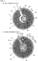
- FIGS. 2 are schematic horizontal sectional views illustrating the structure of the two-cylinder rotary compressor 100 of FIG. 1 .
- FIG. 2(a) is a schematic horizontal sectional view illustrating the first compression unit 10
- FIG. 2(b) is a schematic horizontal sectional view illustrating the second compression unit 20.
- FIG. 1 and FIGS. 2 are illustrations of the two-cylinder rotary compressor 100 in a state in which the first compression unit 10 is brought into a compression state and the second compression unit 20 is brought into a non-compression state (rest state).
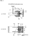
- FIGS. 3 and FIGS. 4 are enlarged views illustrating a main part of a vicinity of a second vane 24 of the second compression unit 20 of the two-cylinder rotary compressor 100 of FIG. 1 .
- FIGS. 3 are views illustrating the vicinity of the second vane 24 in a state in which the second compression unit 20 performs refrigerant compressing action.
- FIG. 3(a) is a horizontal sectional view illustrating the vicinity of the second vane 24, and
- FIG. 3(b) is a vertical sectional view illustrating the vicinity of the second vane 24.
- FIGS. 4 are views illustrating the vicinity of the second vane 24 of the second compression unit 20 in the rest state (state in which the second compression unit 20 does not perform the refrigerant compressing action).
- FIG. 4(a) is a horizontal sectional view illustrating the vicinity of the second vane 24, and
- FIG. 4(b) is a vertical sectional view illustrating the vicinity of the second vane 24.
- the two-cylinder rotary compressor 100 is one of components of a refrigeration cycle adopted in a heat pump apparatus such as an air-conditioning apparatus or a water heater. Further, the two-cylinder rotary compressor 100 has a function of sucking a fluid (such as refrigerant or a heating medium (water, antifreezing fluid, or other medium)), compressing the fluid into a high-temperature and high-pressure state, and then discharging the fluid.
- a fluid such as refrigerant or a heating medium (water, antifreezing fluid, or other medium
- the two-cylinder rotary compressor 100 includes a compression mechanism 99 including the first compression unit 10 and the second compression unit 20, and an electric motor 8 for driving the first compression unit 10 and the second compression unit 20 through a drive shaft 5.
- the closed shell 3 is, for example, a cylindrical closed container having a closed upper end portion and a closed lower end portion.
- a lubricating oil storage portion 3a for storing lubricating oil for lubricating the compression mechanism 99 is formed in a bottom portion of the closed shell 3.
- a compressor discharge pipe 2 is arranged in an upper portion of the closed shell 3 so as to be communicated to the internal space 7 of the closed shell 3.
- the electric motor 8 is variable in, for example, operating frequency (or rotating frequency) through inverter control or other control, and includes a stator 8b and a rotor 8a.
- the stator 8b is formed into a substantially cylindrical shape, and an outer peripheral portion of the stator 8b is fixed to the closed shell 3 by, for example, shrinkage fitting.
- a coil is wound around the stator 8b. Electric power is supplied to the coil from an external power source.
- the rotor 8a is formed into a substantially cylindrical shape, and is arranged in an inner peripheral portion of the stator 8b with a predetermined gap formed between an inner peripheral surface of the stator 8b and the rotor 8a.
- the drive shaft 5 is fixed to the rotor 8a, and the electric motor 8 and the compression mechanism 99 are connected to each other through intermediation of the drive shaft 5. That is, the electric motor 8 is rotated to transmit rotational power to the compression mechanism 99 through the drive shaft 5.
- the drive shaft 5 includes a long shaft portion 5a forming an upper portion of the drive shaft 5, a short shaft portion 5b forming a lower portion of the drive shaft, eccentric pin shaft portions 5c and 5d formed between the long shaft portion 5a and the short shaft portion 5b, and an intermediate shaft portion 5e.
- a center axis of the eccentric pin shaft portion 5c is eccentric to center axes of the long shaft portion 5a and the short shaft portion 5b by a predetermined distance, and the eccentric pin shaft portion 5c is arranged in a first cylinder chamber 12 of the first compression unit 10 described later.
- a center axis of the eccentric pin shaft portion 5d is eccentric to the center axes of the long shaft portion 5a and the short shaft portion 5b by a predetermined distance, and the eccentric pin shaft portion 5d is arranged in a second cylinder chamber 22 of the second compression unit 20 described later.
- the eccentric pin shaft portion 5c and the eccentric pin shaft portion 5d are arranged to be 180° out of phase with each other.
- the eccentric pin shaft portion 5c and the eccentric pin shaft portion 5d are connected to each other by the intermediate shaft portion 5e.
- the intermediate shaft portion 5e is arranged in a through hole of an intermediate partition plate 4 described later.
- the long shaft portion 5a is rotatably supported by a bearing portion 60a of a first support member 60
- the short shaft portion 5b is rotatably supported by a bearing portion 70a of a second support member 70.
- eccentric pin shaft portions 5c and 5d of the drive shaft 5 are configured to perform eccentric rotary motion in the first cylinder chamber 12 and the second cylinder chamber 22, respectively.
- the compression mechanism 99 includes the rotary-type first compression unit 10 arranged in an upper portion of the compression mechanism 99, and the rotary-type second compression unit 20 arranged in a lower portion thereof.
- the first compression unit 10 and the second compression unit 20 are arranged below the electric motor 8.
- the first support member 60, a first cylinder 11 forming the first compression unit 10, the intermediate partition plate 4, a second cylinder 21 forming the second compression unit 20, and the second support member 70 are sequentially stacked from an upper side to a lower side of the compression mechanism 99.
- the first compression unit 10 includes the first cylinder 11, a first piston 13, and a first vane 14.
- the first cylinder 11 is a flat plate member having a substantially cylindrical through hole formed therethrough in an up-and-down direction to be substantially concentric with the drive shaft 5 (more specifically, the long shaft portion 5a and the short shaft portion 5b).
- One end portion (upper end portion in FIG. 1 ) of the through hole is closed by a flange portion 60b of the first support member 60, and the other end portion (lower end portion in FIG. 1 ) of the through hole is closed by the intermediate partition plate 4.
- the first cylinder chamber 12 is defined.
- the first piston 13 is arranged in the first cylinder chamber 12 of the first cylinder 11.
- the first piston 13 is formed into a ring shape, and is slidably arranged on the eccentric pin shaft portion 5c of the drive shaft 5.
- a vane groove 19 is formed in the first cylinder 11.
- the vane groove 19 is communicated to the first cylinder chamber 12, and extends in a radial direction of the first cylinder chamber 12.
- the first vane 14 is slidably arranged in the vane groove 19.
- a distal end portion 14a of the first vane 14 abuts on an outer peripheral portion of the first piston 13, thereby partitioning the first cylinder chamber 12 into a suction chamber 12a and a compression chamber 12b.
- a vane back chamber 15 is formed behind the vane groove 19, that is, behind the first vane 14.
- the vane back chamber 15 is formed so as to pass through the first cylinder 11 in the up-and-down direction. Further, an upper opening portion of the vane back chamber 15 is partially open toward the internal space 7 of the closed shell 3, thereby enabling the lubricating oil stored in the lubricating oil storage portion 3a to flow into the vane back chamber 15.
- the lubricating oil flowing into the vane back chamber 15 flows into a space between the vane groove 19 and the first vane 14, thereby reducing slide resistance therebetween.
- the two-cylinder rotary compressor 100 according to Embodiment 1 is configured to discharge the refrigerant, which is compressed by the compression mechanism 99, into the internal space 7 of the closed shell 3. Accordingly, the vane back chamber 15 has the same high-pressure atmosphere as that of the internal space 7 of the closed shell 3.
- the second compression unit 20 includes the second cylinder 21, a second piston 23, and the second vane 24.
- the second cylinder 21 is a flat plate member having a substantially cylindrical through hole formed therethrough in the up-and-down direction to be substantially concentric with the drive shaft 5 (more specifically, the long shaft portion 5a and the short shaft portion 5b).
- One end portion (upper end portion in FIG. 1 ) of the through hole is closed by the intermediate partition plate 4, and the other end portion (lower end portion in FIG. 1 ) of the through hole is closed by a flange portion 70b of the second support member 70.
- the second cylinder chamber 22 is defined.
- the second piston 23 is arranged in the second cylinder chamber 22 of the second cylinder 21.
- the second piston 23 is formed into a ring shape, and is slidably arranged on the eccentric pin shaft portion 5d of the drive shaft 5.
- a vane groove 29 is formed in the second cylinder 21.
- the vane groove 29 is communicated to the second cylinder chamber 22, and extends in a radial direction of the second cylinder chamber 22.
- the second vane 24 is slidably arranged in the vane groove 29.
- a distal end portion 24a of the second vane 24 abuts on an outer peripheral portion of the second piston 23, thereby partitioning the second cylinder chamber 22 into a suction chamber and a compression chamber similarly to the first cylinder chamber 12.
- a vane back chamber 25 is formed behind the vane groove 29, that is, behind the second vane 24.
- the vane back chamber 25 is formed so as to pass through the second cylinder 21 in the up-and-down direction. Further, upper and lower opening portions of the vane back chamber 25 are closed by the intermediate partition plate 4 and the flange portion 70b of the second support member 70, respectively.
- the vane back chamber 25 and the internal space 7 of the closed shell 3 are communicated to each other by a passage 30 communicated from an outer peripheral surface of the second cylinder 21 to the vane back chamber 25.
- the lubricating oil stored in the lubricating oil storage portion 3a can flow into the vane back chamber 25 through the passage 30. Accordingly, the vane back chamber 25 has the same high-pressure atmosphere as that of the internal space 7 of the closed shell 3. Further, the lubricating oil flowing into the vane back chamber 25 flows into a space between the vane groove 29 and the second vane 24, thereby reducing slide resistance therebetween.
- At least one of the opening portions of the vane back chamber 25 may be open toward the internal space 7 of the closed shell 3, thereby enabling the lubricating oil stored in the lubricating oil storage portion 3a to flow into the vane back chamber 25 also through the opening portion.
- a suction muffler 6 for causing gaseous refrigerant to flow into the first cylinder chamber 12 and the second cylinder chamber 22 is connected to each of the first cylinder 11 and the second cylinder 21.
- the suction muffler 6 includes a container 6b, an inflow pipe 6a, an outflow pipe 6c, and an outflow pipe 6d.
- Low-pressure refrigerant that flows out of an evaporator constructing the refrigeration cycle is stored in the container 6b.
- the inflow pipe 6a guides the low-pressure refrigerant from the evaporator into the container 6b.
- the outflow pipe 6c guides, into the first cylinder chamber 12 of the first cylinder 11, the gaseous refrigerant of the refrigerant stored in the container 6b.
- the outflow pipe 6d guides, into the second cylinder chamber 22 of the second cylinder 21, the gaseous refrigerant of the refrigerant stored in the container 6b.
- the outflow pipe 6c of the suction muffler 6 is connected to the cylinder suction passage 17 (passage communicated to the first cylinder chamber 12) of the first cylinder 11, and the outflow pipe 6d of the suction muffler 6 is connected to the cylinder suction passage 27 (passage communicated to the second cylinder chamber 22) of the second cylinder 21.
- the discharge port 18 is formed in the first cylinder 11, and the gaseous refrigerant compressed in the first cylinder chamber 12 is discharged through the discharge port 18.
- the discharge port 18 is communicated to the through hole formed in the flange portion 60b of the first support member 60, and an on-off valve 18a is arranged over the through hole.
- the on-off valve 18a is open when a pressure in the first cylinder chamber 12 is equal to or higher than a predetermined pressure.
- a discharge muffler 63 is mounted onto the first support member 60 so as to cover the on-off valve 18a (that is, the through hole).
- the discharge port 28 is formed in the second cylinder 21, and the gaseous refrigerant compressed in the second cylinder chamber 22 is discharged through the discharge port 28.
- the discharge port 28 is communicated to the through hole formed in the flange portion 70b of the second support member 70, and an on-off valve 28a is arranged over the through hole.
- the on-off valve 28a is open when a pressure in the second cylinder chamber 22 is equal to or higher than a predetermined pressure.
- a discharge muffler 73 is mounted onto the second support member 70 so as to cover the on-off valve 28a (that is, the through hole).
- first compression unit 10 and the second compression unit 20 basically have the same configurations, but detailed configurations of the first compression unit 10 and the second compression unit 20 are different in the following points.
- a suction pressure pressure of the low-pressure refrigerant sucked into the first cylinder chamber 12 and the second cylinder chamber 22
- a discharge pressure pressure in the internal space 7 of the closed shell 3, that is, pressure of high-pressure refrigerant compressed by the compression mechanism 99
- a rear end portion 14b side of the first vane 14 and a rear end portion 24b side of the second vane 24 is applied to both of the distal end portion 14a side of the first vane 14 and the distal end portion 24a side of the second vane 24.
- a pressing force is applied to the first vane 14 in a direction of pressing the first vane 14 toward the first piston 13 side in accordance with a difference between the pressures applied to the distal end portion 14a and the rear end portion 14b
- a pressing force is applied to the second vane 24 in a direction of pressing the second vane 24 toward the second piston 23 side in accordance with a difference between the pressures applied to the distal end portion 24a and the rear end portion 24b.
- a pressing force for pressing the first vane 14 toward the first piston 13 side is applied to the first vane 14 by a compression spring 40. Accordingly, the first vane 14 is always pressed against the first piston 13, thereby partitioning the first cylinder chamber 12 into the suction chamber 12a and the compression chamber 12b. That is, the first compression unit 10 including the first vane 14 always compresses the refrigerant flowing into the first cylinder chamber 12.
- the rear end portion 24b of the second vane 24 is pulled by a tension spring 50 fixed to the closed shell 3 at a spring fixing portion 42. That is, due to a reaction force (elastic force) of the tension spring 50, a pulling force is applied to the second vane 24 in a direction of separating the second vane 24 away from an outer peripheral wall of the second piston 23 (direction of moving the second vane 24 to the rear end portion 24b side). Accordingly, a smaller pressing force for pressing the vane toward the second piston 23 side is applied to the second vane 24 of the second compression unit 20 as compared to the first vane 14 of the first compression unit 10.
- a larger pulling force is applied to the second vane 24 of the second compression unit 20 in the direction of separating the second vane 24 away from the outer peripheral wall of the second piston 23 (direction of moving the second vane 24 to the rear end portion 24b side) as compared to the first vane 14 of the first compression unit 10.
- the second cylinder chamber 22 is partitioned into the compression chamber and the suction chamber, and the second compression unit 20 compresses the refrigerant flowing into the second cylinder chamber 22.
- the distal end portion 24a of the second vane 24 is separated away from the second piston 23, and the second compression unit 20 is brought into the rest state of not compressing the refrigerant in the second cylinder chamber 22.
- the second compression unit 20 including the tension spring 50 includes a retaining mechanism for retaining the second vane 24 when the second vane 24 is separated away from the outer peripheral wall of the second piston 23.
- the retaining mechanism according to Embodiment 1 includes a contact component 52 arranged on a back surface side of the second vane 24 with respect to the rear end portion 24b, a communication hole 51a formed in the second vane 24, and a communication hole 51b formed in the second cylinder 21.
- the contact component 52 is arranged so as to partition the passage 30 and the vane back chamber 25 from each other.
- the contact component 52 has formed therein a communication hole 53 communicating the passage 30 and the vane back chamber 25. That is, the communication hole 53 communicates the internal space 7 of the closed shell 3 and a space formed on the rear end portion 24b side of the second vane 24.
- the second vane 24 side of the contact component 52 is formed of a flat surface portion, and the contact component 52 is arranged so as to keep a predetermined degree of parallelism between the flat surface portion 52a and the rear end portion 24b of the second vane 24.
- One opening portion of the communication hole 51a formed in the second vane 24 is open toward the rear end portion 24b (more specifically, toward a position opposed to a part of the contact component 52 excluding the communication hole 53). Further, the other opening portion of the communication hole 51a is open toward a side surface portion of the second vane 24.
- One opening portion of the communication hole 51b formed in the second cylinder 21 is open toward the vane groove 29. More specifically, the opening portion is open toward a position communicated to the communication hole 51a (position at which the opening portion of the communication hole 51a and the opening portion of the communication hole 51b are opposed to each other) under a state in which the second vane 24 is away from the outer peripheral wall of the second piston 23 and the rear end portion 24b is held in contact with the flat surface portion 52a of the contact component 52. Further, the other opening portion of the communication hole 51b is open toward the cylinder suction passage 27.
- the communication holes 51a and 51b are not limited to the above-mentioned configurations as long as the communication holes 51a and 51b communicate the rear end portion 24b side of the second vane 24 and the cylinder suction passage 27.
- the other opening portion (opening portion that is open toward the side surface portion of the second vane 24 in FIGS. 2 ) of the communication hole 51a may be open toward an upper surface portion of the second vane 24.
- the communication hole 51b communicating the opening portion and the cylinder suction passage 27 includes a passage formed in the intermediate partition plate 4 to be communicated to the opening portion, and another passage formed in the second cylinder 21 to communicate the passage and the cylinder suction passage 27.
- the other opening portion (opening portion that is open toward the side surface portion of the second vane 24 in FIGS. 2 ) of the communication hole 51a may be open toward a bottom surface portion of the second vane 24.
- the communication hole 51b communicating the opening portion and the cylinder suction passage 27 includes a passage formed in the flange portion 70b of the second support member 70 to be communicated to the opening portion, and another passage formed in the second cylinder 21 to communicate the passage and the cylinder suction passage 27.
- the drive shaft 5 When power is supplied to the electric motor 8, the drive shaft 5 is rotated by the electric motor 8 counterclockwise when viewed from directly above (rotated by a phase ⁇ with reference to a position of the vane as illustrated in FIGS. 2 ).
- the eccentric pin shaft portion 5c performs the eccentric rotary motion in the first cylinder chamber 12
- the eccentric pin shaft portion 5d performs the eccentric rotary motion in the second cylinder chamber 22.
- the eccentric pin shaft portion 5c and the eccentric pin shaft portion 5d perform the eccentric rotary motion so as to be 180° out of phase with each other.
- the first piston 13 performs the eccentric rotary motion in the first cylinder chamber 12, thereby compressing the low-pressure gaseous refrigerant sucked into the first cylinder chamber 12 from the outflow pipe 6c of the suction muffler 6 through the cylinder suction passage 17.
- the second piston 23 performs the eccentric rotary motion in the second cylinder chamber 22, thereby compressing the low-pressure gaseous refrigerant sucked into the second cylinder chamber 22 from the outflow pipe 6d of the suction muffler 6 through the cylinder suction passage 27.
- the gaseous refrigerant compressed in the first cylinder chamber 12 is discharged into the discharge muffler 63 through the discharge port 18, and then discharged into the internal space 7 of the closed shell 3 through a discharge port of the discharge muffler 63. Further, when compressed up to the predetermined pressure, the gaseous refrigerant compressed in the second cylinder chamber 22 is discharged into the discharge muffler 73 through the discharge port 28, and then discharged into the internal space 7 of the closed shell 3 through a discharge port of the discharge muffler 73. Then, the high-pressure gaseous refrigerant discharged into the internal space 7 of the closed shell 3 is discharged out of the closed shell 3 through the compressor discharge pipe 2.
- the first compression unit 10 and the second compression unit 20 compress the refrigerant
- the first compression unit 10 and the second compression unit 20 repeat the refrigerant sucking action and the compressing action.
- the discharge pressure is applied to the entire rear end portion 24b of the second vane 24 through the lubricating oil. Accordingly, the pressing force (force for moving the second vane 24 to the second piston 23 side) caused by the difference between the pressures applied to the distal end portion 24a and the rear end portion 24b of the second vane 24 exceeds the pulling force (force for moving the second vane 24 away from the second piston 23) exerted by the tension spring 50. Thus, the distal end portion 24a of the second vane 24 is pressed against the outer peripheral wall of the second piston 23. Therefore, along with the rotation of the drive shaft 5, the second compression unit 20 compresses the refrigerant.
- the second vane 24 is away from the outer peripheral wall of the second piston 23 so that the second compression unit 20 is brought into the rest state (non-compression state).
- the opening portion of the communication hole 51a formed in the second vane 24 and the opening portion of the communication hole 51b formed in the second cylinder 21 start to overlap each other. That is, the communication hole 51a formed in the second vane 24 is communicated through the communication hole 51b to the cylinder suction passage 27 maintained at the suction pressure. Accordingly, through the communication hole 51a and the communication hole 51b, the lubricating oil in the vicinity of the opening portion of the communication hole 51a on the rear end portion 24b side flows into the cylinder suction passage 27, with the result that the pressing force applied to the rear end portion 24b of the second vane 24 is reduced. In this manner, the second vane 24 is further moved in the direction away from the outer peripheral wall of the second piston 23, and the rear end portion 24b of the second vane 24 is brought into contact with the flat surface portion 52a of the contact component 52.
- the discharge pressure is applied to the rear end portion 24b of the second vane 24 only in a range where the second vane 24 is opposed to the communication hole 53 of the contact component 52. Accordingly, the pressing force applied to the second vane 24 is further reduced so that a significant difference is exhibited between the pulling force and the pressing force. As a result, the second vane 24 is stably retained in a state of being away from the outer peripheral wall of the second piston 23.
- the position of the communication hole 51a formed in the second vane 24 and the position of the communication hole 51b formed in the second cylinder 21 do not align with each other, and thus the suction pressure is not led to the communication hole 51b. Further, the lubricating oil is supplied to the entire rear end portion 24b of the second vane 24, and the discharge pressure is applied to the entire rear end portion 24b of the second vane 24, with the result that the pressing force applied to the second vane 24 is increased. In this manner, the significant difference is exhibited between the pressing force and the pulling force applied to the second vane 24.
- the second vane 24 is further moved to the second piston 23 side, and the distal end portion 24a of the second vane 24 is pressed against the outer peripheral wall of the second piston 23. Accordingly, the second compression unit 20 starts action of compressing the refrigerant.
- the pressure applied in the range of the rear end portion 24b of the second vane 24 opposed to the communication hole 53 of the contact component 52 is kept below a predetermined pressure value, that is, the pressure difference between the "suction pressure applied to the entire distal end portion 24a of the second vane 24" and the "discharge pressure applied in the range of the rear end portion 24b of the second vane 24 opposed to the communication hole 53 of the contact component 52" is suppressed at the predetermined value or less. In this manner, the second compression unit 20 can maintain the rest state.
- the second compression unit 20 can maintain the refrigerant compression state.
- FIG. 5 is a graph showing a relationship between a position of the second vane 24 in the two-cylinder rotary compressor 100 of FIG. 1 and the pressing force caused by the pressures applied to the second vane 24.
- FIGS. 6 are explanatory views illustrating a relationship between the pressing force and the pulling force applied to the second vane 24 of the two-cylinder rotary compressor 100 of FIG. 1 .
- FIG. 6(a) is a side view illustrating a state in which the second vane 24 and the flat surface portion 52a of the contact component 52 are not held in contact with each other
- FIG. 6(b) is a side view illustrating a state in which the second vane 24 and the flat surface portion 52a of the contact component 52 are held in contact with each other.
- a suction pressure Ps is applied to the distal end portion 24a of the second vane 24, and a discharge pressure Pd is applied to the rear end portion 24b thereof. Further, a pulling force F exerted by the tension spring 50 is also applied to the second vane 24. Based on a relationship among the pressure Ps, the pressure Pd, and the force F applied to the second vane 24, a state of the second vane 24 is determined.
- the change ⁇ F can be referred to as a difference between the "difference between the pulling force and the pressing force under the state in which the second vane 24 is held in contact with the flat surface portion 52a of the contact component 52 (state in which the retaining mechanism retains the second vane 24)" and the “difference between the pulling force and the pressing force under a state in which the second vane 24 is away from the second piston 23 and the second vane 24 is not held in contact with the flat surface portion 52a of the contact component 52 (state in which the retaining mechanism does not retain the second vane 24).
- the second vane 24 acts as follows. That is, under the state in which the second vane 24 is stably retained, a relationship of F + ⁇ F - (Pd - Ps)A > 0 is satisfied. Further, under a state in which the retention of the second vane 24 is canceled, a relationship of F + ⁇ F - (Pd - Ps)A ⁇ 0 is satisfied.
- the second compression unit 20 is subjected to a smaller pressing force for pressing the second vane 24 toward the second piston 23 side.
- the second compression unit 20 is subjected to a larger pulling force applied to the second vane 24 to separate the second vane 24 in the direction away from the second piston 23.
- the two-cylinder rotary compressor 100 can reduce a compressor loss in a low-load condition, and can achieve enhancement of efficiency of the compressor and increase of a capacity range, thereby being capable of enhancing energy-saving performance in actual load operation.
- the two-cylinder rotary compressor 100 according to Embodiment 1 does not require a mechanical volume control unit including an on-off valve, a switching valve, and a pipe, which are required in the two-cylinder rotary compressor disclosed in Patent Literature 1. Thus, it is possible to prevent increase in size and cost of the two-cylinder rotary compressor 100.
- the two-cylinder rotary compressor 100 includes the retaining mechanism arranged in the second compression unit 20, for retaining the second vane 24 in contact with the second vane 24 when the second vane 24 is moved away from the second piston 23. Accordingly, the two-cylinder rotary compressor 100 according to Embodiment 1 can stably maintain the position of the second vane 24 when the second vane 24 is separated away from the outer peripheral wall of the second piston 23.
- the second compression unit 20 to be brought into the rest state is arranged below the first compression unit 10 is described above.
- the second compression unit 20 to be brought into the rest state may be arranged above the first compression unit 10.
- the two-cylinder rotary compressor 100 of a high-pressure closed shell type is described above, but the above-mentioned second compression unit 20 may be employed in a two-cylinder rotary compressor of another shell type.
- the same effect as the above-mentioned effect can be attained.
- the second compression unit 20 described in Embodiment 1 is employed in a two-cylinder rotary compressor of a semi-closed type and a two-cylinder rotary compressor of a medium-pressure shell type, the same effect as the above-mentioned effect can be attained.
- Embodiment 1 has a feature of being capable of determining whether an operation mode is single operation or parallel operation. Now, description is made of a heat pump apparatus 200 capable of determining whether the operation mode is the single operation or the parallel operation.
- FIG. 7 is a view illustrating a basic configuration of the heat pump apparatus 200 according to Embodiment 1 of the present invention.
- the heat pump apparatus 200 includes the same two-cylinder rotary compressor 100 as illustrated in FIG. 1 , a four-way valve 201, an indoor-side heat exchanger 202, a pressure reducing mechanism 203, and an outdoor-side heat exchanger 204. Those components are connected by a refrigerant circuit pipe 207 to form a vapor-compression refrigeration cycle. Now, a heat pump apparatus for air-conditioning is described as an example of the heat pump apparatus 200.
- the heat pump apparatus 200 can be switched by the four-way valve 201 between heating operation and cooling operation.
- the four-way valve 201 is connected to a side of a heating-operation channel 201a indicated by the solid line of FIG. 7 .
- refrigerant gas compressed into a high-temperature and high-pressure state by the two-cylinder rotary compressor 100 flows into the indoor-side heat exchanger 202, and the indoor-side heat exchanger 202 acts as a heat-rejecting-side heat exchanger (condenser).
- the four-way valve 201 is connected to a side of a cooling-operation channel 201b indicated by the dotted line of FIG. 7 .
- a suction side of the two-cylinder rotary compressor 100 is connected to the indoor-side heat exchanger 202, and the indoor-side heat exchanger 202 acts as a heat-removing-side heat exchanger (evaporator).
- the two-cylinder rotary compressor 100 includes the electric motor 8 and the two compression units 10 and 20, and has such structure that the single operation in which one of the compression units is brought into the non-compression state, and the normal parallel operation in which both the compression units are brought into the compression state are switched passively depending on operation conditions. Specifically, as described above, immediately after start of operation of the two-cylinder rotary compressor 100, and under the state in which the two-cylinder rotary compressor 100 is subjected to the low load, the single operation is performed. When the pressure in the internal space 7 of the closed shell 3 is increased, the parallel operation is performed.
- the indoor-side heat exchanger 202 is arranged in an indoor space B, and the two-cylinder rotary compressor 100, the four-way valve 201, the pressure reducing mechanism 203, and the outdoor-side heat exchanger 204 are arranged in an outdoor space A.
- a heat exchanger temperature sensor 173a for detecting an evaporating temperature or a condensing temperature of the outdoor-side heat exchanger 204 is provided in the outdoor space A.
- An indoor temperature sensor 172 for detecting an indoor temperature, and a heat exchanger temperature sensor 173b for detecting an evaporating temperature or a condensing temperature of the indoor-side heat exchanger 202 are provided in the indoor space B.
- Signals of detection of the heat exchanger temperature sensor 173a, the heat exchanger temperature sensor 173b, and the indoor temperature sensor 172 are input to a heat pump capacity control device 160 described later.
- the sensors used for control of the heat pump apparatus 200 are not limited to the sensors illustrated in FIG. 7 . Temperature sensors arranged on a gas side and a liquid side of the indoor-side heat exchanger 202, a temperature sensor and a pressure sensor arranged on a suction side and a discharge side of the two-cylinder rotary compressor 100, and other sensors may be used appropriately as needed.
- FIG. 8 is a schematic view illustrating the control circuit of the heat pump apparatus 200 according to Embodiment 1 of the present invention.
- An inverter drive control device 150 for driving the two-cylinder rotary compressor 100 by a power source supplied from an AC power source 140, and the heat pump capacity control device 160 are provided in the outdoor space A.
- An operation mode detecting-determining unit 145 is further provided in Embodiment 1 of the present invention, which is a feature of the present invention.
- the heat pump capacity control device 160 is a device for determining the operating frequency of the electric motor 8 so as to bring a temperature detected by the indoor temperature sensor 172 close to a target room temperature set by a target room temperature setting device 171, to thereby control the inverter drive control device 150 so as to cause the electric motor 8 to act at the determined operating frequency.
- the heat pump capacity control device 160 includes a temperature difference detecting unit 163 for detecting a temperature difference between an actual value of the room temperature detected by the indoor temperature sensor 172 and the target value of the room temperature set by the target room temperature setting device 171, an operating frequency setting unit 161, and a signal output unit 162.
- the operating frequency setting unit 161 determines the operating frequency suitable for achieving the target room temperature based on the operation conditions such as the operating frequency and a current operation mode (single operation or parallel operation) detected by the operation mode detecting-determining unit 145 described later, the temperature difference (operation load) detected by the temperature difference detecting unit 163, and the temperature conditions of the indoor-side heat exchanger 202 and the outdoor-side heat exchanger 204 acquired from the various sensors 173a to 173c.
- the signal output unit 162 transmits a command signal to an inverter drive circuit 152 of the inverter drive control device 150, which is described later, so as to cause the electric motor 8 to act at the operating frequency determined by the operating frequency setting unit 161.
- the inverter drive control device 150 is connected to the electric motor 8 of the two-cylinder rotary compressor 100 through intermediation of a hermetic terminal (three-phase terminal) 9 of the closed shell 3.
- the inverter drive control device 150 is a device for converting electric power supplied from the AC power source 140 into a three-phase current suitable for driving the electric motor 8, and then supplying the three-phase current to the electric motor 8.
- the electric motor 8 is a brushless DC motor, and the inverter drive control device 150 vector-controls the brushless DC motor.
- the inverter drive control device 150 includes an inverter circuit 151, the inverter drive circuit 152, and an inverter control constant adjusting unit 153. Based on the operating frequency output from the signal output unit 162 and a control constant output from the inverter control constant adjusting unit 153, the inverter drive circuit 152 adjusts a voltage waveform so as to maintain an optimum operation state, and then outputs the voltage waveform to the inverter circuit 151. Based on the voltage waveform output from the inverter drive circuit 152, the inverter circuit 151 converts electric power supplied from the AC power source 140 into the three-phase current suitable for driving the electric motor 8, and then supplies the three-phase current to the electric motor 8. That is, the inverter circuit 151 converts electric power supplied from the AC power source 140 into an alternating current having the operating frequency determined by the operating frequency setting unit 161, and then supplies the alternating current to the electric motor 8.
- the operation mode detecting-determining unit 145 determines whether the current operation mode is the single operation or the parallel operation. Specifically, the operation mode detecting-determining unit 145 determines whether the current operation mode is the single operation or the parallel operation by observing and analyzing a current waveform of the inverter circuit 151. The result of determination is output to the inverter control constant adjusting unit 153 and the operating frequency setting unit 161.
- FIGS. 9 are graphs showing the torque fluctuations in the two-cylinder rotary compressor 100 of FIG. 7 .
- FIG. 9(a) is a graph showing the torque fluctuation during the single operation
- FIG. 9(b) is a graph showing the torque fluctuation during the parallel operation.
- FIGS. 9 show the horizontal axis represents a rotational phase [deg], and the vertical axis represents rotational torque [N ⁇ m].
- FIGS. 9 show the torque fluctuation occurring in the first compression unit 10, the torque fluctuation occurring in the second compression unit 20, and total torque obtained by superposing the torque fluctuations occurring in the first compression unit 10 and the second compression unit 20.
- the first compression unit 10 causes the torque fluctuation in which a peak is observed at a vicinity of a rotational phase of 180°. Further, the torque fluctuation occurring in the second compression unit 20 brought into the non-compression state is smaller than the torque fluctuation occurring in the first compression unit 10 brought into the compression state.
- the total torque has a torque fluctuation in which one large convex profile (having a torque fluctuation range of 120 [N ⁇ m]) is observed in one cycle nearly similarly to the torque fluctuation occurring in the first compression unit 10.
- the torque fluctuation in which the peak is observed at the vicinity of the rotational phase of 180° occurs in the first compression unit 10
- the torque fluctuation in which a peak is observed at a vicinity of a rotational phase of 0° occurs in the second compression unit 20 having an opposite phase.
- the torque fluctuations cancel out each other. Accordingly, the total torque has a torque fluctuation in which two small convex profiles having a fluctuation range of about 40 [N ⁇ m] are observed in one cycle.
- the single operation and the parallel operation are common in that a current waveform of the motor has three convex profiles in one cycle.
- a current value is proportional to the above-mentioned total torque, and hence different characteristics are observed in the current waveforms of the motor in the single operation and the parallel operation.
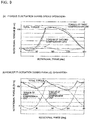
- FIGS. 10 are graphs showing characteristics during the single operation when the electric motor 8 of the two-cylinder rotary compressor 100 of FIG. 7 is a six-pole motor.
- FIG. 10(a) is a graph showing a current waveform of the motor
- FIG. 10(b) is a graph showing intensities of respective frequency components.
- the horizontal axis of FIG. 10(a) represents time, and the vertical axis thereof represents a current.
- the horizontal axis of FIG. 10(b) represents frequency, and the vertical axis thereof represents intensity.
- FIGS. 11 are graphs showing characteristics during the parallel operation when the electric motor 8 of the two-cylinder rotary compressor 100 of FIG. 7 is a six-pole motor.
- FIG. 11(a) is a graph showing a current waveform of the motor
- FIG. 11(b) is a graph showing intensities of respective frequency components.
- the horizontal axis of FIG. 11(a) represents time, and the vertical axis thereof represents a current.
- the horizontal axis of FIG. 11(b) represents frequency, and the vertical axis thereof represents intensity.
- the operation mode detecting-determining unit 145 can determine the operation mode by observing the current waveform of the motor. For example, the following determination method is used. Specifically, the intensity of the 1f component and the intensity of the 2f component are compared to each other. When the 1f component is equal to or 1.5 times larger than the 2f component, it is determined that the operation mode is the single operation.
- the operation mode is the parallel operation.
- the 1f component is 1.3 times larger than the 2f component and 1.5 times smaller than the 2f component, determination of the operation mode is temporarily reserved and detection of a current form is continued.
- the operation mode can be determined.
- the temperature difference detecting unit 163 of the heat pump capacity control device 160 detects a temperature difference between an actual value of the room temperature detected by the indoor temperature sensor 172 and a target value of the room temperature set by the target room temperature setting device 171. Then, based on the temperature difference, the result that the current operation mode is the parallel operation, and the temperatures output from the heat exchanger temperature sensors 173a and 173b, the operating frequency setting unit 161 calculates (determines) an operating frequency suitable for achieving the target value of the room temperature.
- the command signal is transmitted from the signal output unit 162 to the inverter drive circuit 152 so as to cause the electric motor 8 to act at the determined operating frequency.
- the medium heating operation is performed under a medium pressure difference at medium torque and medium speed, and the parallel operation is continued.
- the operation mode detecting-determining unit 145 determines that the operation mode is the single operation, the difference between the actual value of the room temperature detected by the indoor temperature sensor 172 and the target value of the room temperature set by the target room temperature setting device 171 is detected, and the operating frequency suitable for achieving the target room temperature is determined. Further, the command signal is transmitted from the signal output unit 162 to the inverter drive circuit 152 so as to cause the electric motor 8 to act at the determined operating frequency.
- the heat pump capacity control device 160 needs to perform control in the following manner. That is, the heat pump capacity control device 160 needs to control an output current of the inverter circuit 151 so as to attain a nearly equal value of load processing capacity (heating capacity or cooling capacity) of the heat pump apparatus 200 in the single operation and the parallel operation (that is, so as to prevent a change of load processing capacity).
- the single operation is performed at an operating frequency (which is synonymous with a rotating frequency) substantially twice that of the parallel operation, thereby attaining such characteristics that the refrigerant gas compressed in the cylinder chamber leaks less in the single operation than in the parallel operation. Accordingly, volumetric efficiency ⁇ v1 in the single operation is higher than volumetric efficiency ⁇ v2 in the parallel operation.
- the operating frequency f1 during the single operation (corresponding to an output frequency of the inverter drive control device 150 and a rotating frequency of the electric motor 8) needs to satisfy the following relationship.
- f 1 f 2 ⁇ 2 ⁇ ⁇ v 2 / ⁇ v 1.
- the difference between the volumetric efficiency ⁇ v2 and the volumetric efficiency ⁇ v1 is approximately 20 % at a maximum.
- the operation may be performed so that the operating frequency f1 is set in the following operating frequency range obtained by subtracting the difference from the double of the operating frequency f2 during the parallel operation. f 2 ⁇ 2 > f 1 > f 2 ⁇ 2 ⁇ 0.8.
- the operation when the operation mode is switched from the single operation to the parallel operation, the operation may be performed so that the operating frequency f2 during the parallel operation is set in the following operating frequency range so as to be slightly higher than half of the operating frequency during the single operation.
- a drive current waveform during the single operation ( FIGS. 10 ) has such a characteristic that the 1f component is significantly larger than the 2f component and the 3f component.
- the maximum current value has a relatively steep slope in the convex profile, the operating frequency of the drive current to be supplied is increased, and the fluctuation rate at the maximum current is relatively high. Accordingly, there is a fear in that an overcurrent occurs.
- an adjustment method of gently increasing the current is employed in the heat pump capacity control device 160.
- the heat pump apparatus 200 of Embodiment 1 it is possible to promptly determine whether the operation mode is the single operation or the parallel operation.
- the output frequency of the inverter circuit 151 necessary for achieving the target temperature can be uniquely determined, and the refrigeration cycle can be stably controlled.
- the heat pump apparatus 200 according to Embodiment 1 includes the two-cylinder rotary compressor 100 having the retaining mechanism. Thus, at a vicinity of a point in time when switching the operation mode, the operation state can be stabilized between the compression state and the non-compression state.
- an electromagnetic pressure switching unit such as the four-way valve and a pipe for leading a switched pressure are not needed outside the closed shell 3. Accordingly, upsizing and cost increase can be minimized.
- a compressor loss can be reduced under a low-load condition, and enhancement of efficiency of the compressor and increase of a capacity range can be achieved, thereby being capable of enhancing energy-saving performance in actual load operation.
- Embodiment 1 description is made of the method of comparing the current waveforms of the motor having three convex profiles in one cycle, and the intensities of the respective frequency components when the electric motor 8 of the two-cylinder rotary compressor 100 is the six-pole motor.
- a four-pole motor is different in that a current waveform of the motor has two convex profiles in one cycle, but has such a characteristic that, out of the two convex profiles, a first convex profile is larger than a second convex profile during the single operation.
- Embodiment 2 is different from Embodiment 1 in a method of determining the operation mode. Now, Embodiment 2 according to the present invention is described with reference to the drawings. Note that, in the following, differences of Embodiment 2 from Embodiment 1 are mainly described.
- FIGS. 12 are schematic side views of a retaining mechanism of the two-cylinder rotary compressor 100 arranged in the heat pump apparatus 200 according to Embodiment 2 of the present invention.
- FIG. 12(a) is a view illustrating the compression state
- FIG. 12(b) is a view illustrating the non-compression state (rest state).
- the contact component 52 with which the second vane 24 of the second compression unit 20 is brought into contact, is formed of a magnet, and a magnetized conduction plate 45 that is magnetized is mounted on the contact component 52.
- the magnetized conduction plate 45 is connected through conduction wires 46 to a pair of hermetic terminals (two-phase terminals) 47 mounted to the closed shell 3.
- the magnetized conduction plate 45 is divided into an upper magnetized conduction plate 45a and a lower magnetized conduction plate 45b across the tension spring 50. In the compression state, the upper magnetized conduction plate 45a and the lower magnetized conduction plate 45b are brought into a non-conduction state.
- a switching unit includes the magnetized conduction plate 45.
- FIG. 13 is a schematic view illustrating a control circuit of the heat pump apparatus 200 according to Embodiment 2 of the present invention.
- the operation mode detecting-determining unit 145 When detecting conduction between the pair of hermetic terminals (two-phase terminals) 47 by acquiring the conduction signal, the operation mode detecting-determining unit 145 arranged outside the closed shell 3 determines that the heat pump apparatus 200 is in the non-compression state (single operation). When acquiring no conduction signal to detect non-conduction, the operation mode detecting-determining unit 145 determines that the heat pump apparatus 200 is in the compression state (parallel operation).
- the heat pump apparatus 200 is controlled using the inverter drive control device 150 and the heat pump capacity control device 160.
- Embodiment 2 the same effects as those of Embodiment 1 can be attained. That is, the compressor loss can be reduced under a low-load condition, and the enhancement of the efficiency of the compressor and the increase of the capacity range can be achieved, thereby being capable of enhancing the energy-saving performance in the actual load operation.
- Embodiment 3 is different from Embodiment 1 in a method of determining the operation mode. Now, Embodiment 3 according to the present invention is described with reference to the drawings. Note that, in the following, differences of Embodiment 3 from Embodiment 1 are mainly described.
- FIGS. 14 are graphs showing characteristics during the single operation of the two-cylinder rotary compressor 100 of FIG. 7 . More specifically, FIG. 14(a) is a graph showing a waveform obtained by calculating a torque fluctuation during the single operation based on the current waveform of the inverter output ( FIG. 10(a) ). FIG. 14(b) is a bar graph showing intensities of respective frequency components (square of a torque value) obtained by subjecting this torque fluctuation waveform to the FFT analysis. Similarly, FIGS. 15 are graphs showing characteristics during the parallel operation of the two-cylinder rotary compressor 100 of FIG. 7 .
- FIG. 15(a) is a graph showing a waveform obtained by calculating a torque fluctuation during the parallel operation based on the current waveform of the inverter output ( FIG. 11(a) ).
- FIG. 15(b) is a bar graph showing intensities of respective frequency components (square of a torque value) obtained by subjecting this torque fluctuation waveform to the FFT analysis.
- the horizontal axis represents time
- the vertical axis represents torque [N ⁇ m].
- the horizontal axis represents a frequency
- the vertical axis represents intensity.
- a primary component (If) corresponding to the operating frequency is maximum.
- a secondary component (2f) corresponding to the double of the operating frequency is maximum.
- Embodiment 1 the FFT analysis is directly conducted on the current waveform of the inverter output, and the intensities of the respective frequency components are analyzed. In this manner, whether the operation mode is the single operation or the parallel operation is determined. On the other hand, in Embodiment 3, after the current waveform of the inverter output is converted into the torque fluctuation waveform, the FFT analysis is conducted on the current waveform of the inverter output, and the intensities of the respective frequency components are analyzed. Thus, a difference between the single operation and the parallel operation can be more clearly determined.
- the operation mode can be determined relatively easily by measuring and comparing maximum values and minimum values of the torque fluctuation waveforms without conducting the FFT analysis.
- the single operation has a characteristic of having a range where the torque is negative, but the parallel operation has such characteristics that the minimum value of the torque fluctuation waveform is positive, and that a ratio between the maximum value and the minimum value is approximately double. Accordingly, whether the operation mode is the single operation or the parallel operation can be determined easily based on the difference in characteristics.
- the maximum value and the minimum value are shown at one-cycle intervals during the single operation, whereas the maximum value and the minimum value are shown at half-cycle intervals during the parallel operation. Accordingly, the operation mode can also be determined based on the difference in time intervals.
- Embodiment 3 the same effects as those of Embodiment 1 can be attained. That is, the compressor loss can be reduced under a low-load condition, and the enhancement of the efficiency of the compressor and the increase of the capacity range can be achieved, thereby being capable of enhancing the energy-saving performance in the actual load operation. Further, in Embodiment 3, whether the operation mode is the single operation or the parallel operation is determined based on the torque fluctuation waveforms. Thus, as compared to Embodiment 1, the operation mode can be determined more clearly.
- Embodiment 1 or 2 description is made of the heat pump apparatus using the two-cylinder compressor of a closed high-pressure shell type (in which the compression units and the electric motor are arranged in the closed shell under the same discharge pressure).
- the same effects can be attained using the same unit.
- the same effects can be attained even in a case of a semi-closed type.
- the same effects can be attained even in a case of a medium-pressure shell type or a low-pressure shell type.
- control method performed by detecting and determining the operation mode, and the mechanism for keeping the non-compression state of separating the vane from the compression chamber side which are described in Embodiment 1 and Embodiment 2, are applicable to a rotary compressor of another type except for the above-mentioned rolling piston type.
- rotary compressor types such as a two-cylinder rocking piston type in which a vane and a piston are separable from each other (are not integrated with each other), a two-cylinder rotary vane type, and a two-vane rotary vane type.
- a compression unit of a rocking piston type capable of separating a vane is disclosed in Patent Literature 4.
- the present invention corresponds to a case of forming the compression unit into two cylinders, and enabling one of the two cylinders to be switched to a non-compression state.
- a compression unit of a two-vane rotary vane type is disclosed in Patent Literature 5.
- the present invention corresponds to a case of separating one of two vanes and enabling one of the two vanes to be switched to a non-compression state.
- the present invention corresponds to a case of forming the compression unit of the two-vane rotary vane type disclosed in Patent Literature 5 into two upper and lower cylinders, and enabling one of the two cylinders to be switched to a non-compression state.
- control method performed by detecting and determining the operation mode according to Embodiment 1 or Embodiment 2 is not limited to the above-mentioned two-cylinder rotary compressor of the rolling piston type.
- the control method is applicable to another compression type.
- the control method may be applied to, instead of the two-cylinder rolling piston type, a rotary compression type (such as a rocking piston type or a rotary vane type) in which two compression units are arranged in two cylinders or one cylinder, a scroll compression type having two scroll compression units, or a two-cylinder reciprocating compressor.
- a valve opening/closing mechanism is arranged on a suction side of one of the two compression units.
- the valve is closed under a low-load condition involving a small pressure difference between the suction pressure (Ps) and the discharge pressure (Pd), and one of the compression units can be kept in the non-compression state.
- a capacity control device implemented by the operation mode detecting-determining unit according to Embodiment 1 or Embodiment 2 is applicable.
- valve opening/closing mechanism is added, but there is no switching circuit for changing a leading pressure as disclosed in Patent Literature 1 or Patent Literature 2.
- the size is increased as compared to the two-cylinder rolling piston type described in Embodiment 1 or Embodiment 2, which brings a small improving effect.
- Embodiment 1 and Embodiment 2 as the pulling force, the elastic force exerted by the tension spring 50 and the magnetic force exerted by the magnet are exemplified, but also an inertial force (centrifugal force) may be employed. That is, the second vane 24 is movable in the vane groove 29 only by the pressure difference between the "suction pressure applied to the distal end portion 24a of the second vane 24" and the "discharge pressure applied to the rear end portion 24b of the second vane 24". Accordingly, even when the tension spring 50 is not arranged in the second compression unit 20 of the two-cylinder rotary compressor 100 described in Embodiment 1 or Embodiment 2, the present invention can be carried out.
- an inertial force centrifugal force
- the first compression unit 10 compresses the refrigerant, under a state in which the distal end portion 14a of the first vane 14 is pressed against the outer peripheral wall of the first piston 13, the first vane 14 is moved in the vane groove 19 while following the eccentric rotary motion of the first piston 13.
- the second compression unit 20 compresses the refrigerant, under a state in which the distal end portion 24a of the second vane 24 is pressed against the outer peripheral wall of the second piston 23, the second vane 24 is moved in the vane groove 29 while following the eccentric rotary motion of the second piston 23.
- Embodiment 1 or Embodiment 3 on the assumption that the two-cylinder compressor includes a mechanism for passively switching the operation mode between the single operation and the parallel operation depending on a load condition, description is made of the operation mode detecting-determining unit for determining the current operation mode based on the electric signal acquired from the inverter drive control device that supplies drive power to the electric motor.
- application of the operation mode detecting-determining unit according to the present invention is not limited to the above-mentioned two-cylinder compressor, and the operation mode detecting-determining unit is also effective in the following two-cylinder compressor. That is, a pressure in a cylinder chamber and a pressure on a vane back surface are switched using an electromagnetic switching valve as disclosed in Patent Literature 1 or Patent Literature 2.
- the operation mode detecting-determining unit is effective as an auxiliary unit for confirming whether the current operation mode is the single operation or the parallel operation.
Description
- The present invention relates to a heat pump apparatus using a compressor including two cylinders or two compression units.
- Hitherto, in a heat pump apparatus such as an air-conditioning apparatus or a water heater, a vapor-compression refrigeration cycle using a refrigerant compressor is generally employed. That is, the vapor-compressor refrigeration cycle constructed by connecting the refrigerant compressor, a condenser, a pressure reducing unit, and an evaporator to each other through pipes is installed in the heat pump apparatus, thereby being capable of carrying out operation in accordance with intended use (such as air-conditioning use and hot water supply use).
- Incidentally, in recent years, regulations on greenhouse gas emission were incorporated in the Kyoto Protocol in 1997 from the viewpoint of preventing global warming, and the Kyoto Protocol came into force as international law in 2005. In order to reduce the amount of carbon dioxide emission and achieve energy saving, in the field of HVAC, the heat pump apparatus has widely been spread in place of conventional water heaters and conventional room heaters, and efficiency of the heat pump apparatus has further been increased.
- Regulations on energy saving of air-conditioning apparatus have been tightened in each country. In particular, as compared to the conventional standards, the latest standards have such a feature that energy-saving performance is evaluated under an operation condition closer to an actual load. Conventionally, in Japan, when indicating energy-saving performance, efficiency evaluation was indicated by a cooling-heating average coefficient of performance (COP) under a rated condition. Since 2011, the efficiency evaluation has been indicated by an annual performance factor (APF) calculated based on COPs under four cooling-heating conditions including a medium condition.
- In addition, in Europe, since 2012, there has been adopted a method of indicating energy-saving performance based on new standards for evaluating and calculating a seasonal energy efficiency ratio (SEER) of cooling and a seasonal coefficient of performance (SCOP) of heating under four cooling conditions and four heating conditions added to a low-load condition.
- In this case, the low-load condition refers to a condition that a temperature difference between an outside temperature and an indoor temperature is small and a small quantity of heat is necessary for keeping the indoor temperature constant. The low-load condition also refers to a state in which a difference between a high pressure (Pd) and a low pressure (Ps) is small in the vapor-compressor refrigeration cycle and a small quantity of heat is necessary in a steady state (for example, 25 % or less of rated capacity).
- Except for start of operation, about 10 % to 50 % of capacity under a rated condition is needed during steady operation, and a time period of operation in a range of from the low-load condition to the medium condition is longer than that of the rated operation. Accordingly, when substantially evaluating annual energy-saving performance, it is a new challenge to increase a COP in the low-load condition that is out of evaluation in the conventional standards.
- Further, hitherto, ON-OFF control has been employed as a measure to adjust cooling or heating capacity, but has a problem in that a fluctuation range of temperature adjustment is wide and a vibration noise level is high, and another problem in that an energy loss is significant. In order to solve the problems, inverter control of varying a rotation speed of a drive motor of a compressor has widely been spread.
- In recent years, the air-conditioning apparatus has been required to reduce a startup time period and to have increased heating capacity under a low-outside-temperature environment, and has been needed to have rated capacity with a certain level or more. On the other hand, houses are being highly air-tightened and heat-insulated, thereby reducing capacity necessary during the steady operation, and enlarging an operation capacity range. Accordingly, the air-conditioning apparatus is required to maintain high efficiency in a wider operation range and a wider rotation speed range, thereby being difficult to maintain high efficiency in operation performed at low speed and low-load capacity simply by employing control of the rotation speed performed by the related-art inverter.
- In this context, a refrigerant compressor taking a measure to mechanically vary a displacement volume (mechanical volume control) comes into focus again. For example, in
Patent Literature 1, there is disclosed such a configuration that in a rotary compressor of a two-cylinder rolling piston type, one of compression units is brought into a non-compression state under a low load, thereby halving a flow rate of circulation of refrigerant. In this configuration, operation can be carried out without reducing a rotation speed of an electric motor. - Thus, efficiency of the compressor can be increased. As a specific measure, there is disclosed such a measure that when one of the compression units is brought into the non-compression state, a high pressure is led into one of cylinder chambers, and a pressure in a back pressure chamber on a blade (vane) back surface is changed to a medium pressure so that the blade (vane) is separated away from a rolling piston due to a pressure difference between the high pressure and the medium pressure, thereby bringing one of the compression units into the non-compression state (rest cylinder operating method).
- Further, in
Patent Literature 2, there is disclosed a configuration of a refrigeration cycle apparatus including a switching unit and a control unit for switching and controlling operation between single operation in which one of two compression units is brought into a non-compression state, and parallel operation in which both the two compression units are brought into a compression state in the two-cylinder (synonymous with a two-cylinder type) rotary compressor as disclosed inPatent Literature 1. - The refrigeration cycle apparatus has a feature of including the control unit for controlling, based on an output frequency of an inverter circuit, switching performed by the switching unit, and for varying a point of the switching based on a temperature of a condenser of a refrigeration cycle.
- Further, in
Patent Literature 3, there is disclosed a multi-cylinder rotary compressor that accommodates an electric element in a closed shell having a high-pressure interior, and also accommodates therein a plurality of compression units to be driven by the electric element. As disclosed inPatent Literature 3, a tension spring for pulling the vane outward is arranged on a back surface side of a vane of at least one of the plurality of compression units, and another spring for pressing the vane inward is arranged on a back surface side (rear end portion side) of a vane of another one of the compression units. - At the time of startup, a pressure difference between a discharge pressure and a suction pressure is small. Thus, on the compression unit side including the tension spring arranged on the vane, a pulling force of the tension spring is larger than a force for pressing the vane inward. That is, the pulling force of the tension spring overcomes the force for pressing the vane inward, and the vane is separated away from a rolling piston and brought into a non-compression state. This technology aims to secure a long period of time for light-load operation at the time of startup, to thereby perform startup gently and smoothly.
- Patent Literature 6 is considered to be the closest relevant prior art and discloses a compressor apparatus which may vary in compressing capacity in response to a load.
- Patent Literature 7 is considered to be the relevant prior art and discloses a multicylindrical rotary compressor in which a rotation number of a driving element is controlled by control means.
-
Patent Literature 8 is considered to be the relevant prior art and discloses a multicylindrical rotary compressor constituted to be usable by switching a first operation mode in which first and second rotary compression elements perform compression works, and a second operation mode in which substantially the only first rotary compression element performs the compression work, a compression system provided with the multicylindrical rotary compressor, and a freezing device using the system. - Patent Literature 9 is considered to be the relevant prior art and discloses a refrigeration cycle device which varies capacity efficiently.
-
Patent Literature 10 is considered to be the relevant prior art and discloses a variable capacity compressor which includes a four-way valve having a suction gas distribution function and a high-pressure injection function, and is designed to gain a driving source of the four-way valve in an initial parallel pressure state. -
- Patent Literature 1:
- Japanese Unexamined Patent Application Publication
JP Hei 1-247 786 A page 3,FIG. 1 , andFIG. 2 ) - Patent Literature 2:
- Japanese Unexamined Patent Application Publication
JP Hei 4-006 349 A FIG. 1 to FIG. 3 ) - Patent Literature 3:
- Japanese Unexamined Utility Model Application Publication
JP Sho 61-159 691 U FIG. 1 to FIG. 3 ) - Patent Literature 4:
- Japanese Unexamined Utility Model Application Publication
JP Sho 55-180 989 U - Patent Literature 5:
- Japanese Unexamined Patent Application Publication
JP Sho 60-113 084 A - Patent Literature 6:
-
GB 2 214 572 A - Patent Literature 7:
-
EP 1 681 468 A2 - Patent Literature 8:
-
EP 1 672 219 A2 - Patent Literature 9:
-
WO 2012/153521 A1 - Patent Literature 10:
-
US 2006/193732 A1 - In the two-cylinder rotary compressor disclosed in
Patent Literature 1 orPatent Literature 2, in order to bring one of the compression units into the non-compression state at the time of a low load, that is, in order to switch a pressure applied to the rear end portion of the vane, it is necessary that the switching unit such as an electromagnetic four-way valve, pipes for leading the switched pressure, and other members be arranged outside the closed shell. The two-cylinder rotary compressor disclosed inPatent Literature 1 orPatent Literature 2 needs the arrangement of the switching unit and the pipes as described above, which leads to a problem of increased size and cost as compared to a related-art two-cylinder rotary compressor. - In a case of the two-cylinder rotary compressor disclosed in
Patent Literature 3, at the time of startup, due to pressure reduction at the rear end portion of the vane, the force for pressing the vane inward is smaller than the pulling force exerted by the tension spring so that the vane is separated away from the rolling piston to be brought into the non-compression state. That is, in the case of the two-cylinder rotary compressor disclosed inPatent Literature 3, operation can be automatically switched between the compression state and the non-compression state without using the pipes arranged outside the closed shell as disclosed inPatent Literature 1 orPatent Literature 2. The two-cylinder rotary compressor disclosed inPatent Literature 3 is effective in this regard. - However, the technology of
Patent Literature 3 originally aims to slightly moderate sharp pressure rise and load increase at the time of startup. Thus, no investigation is conducted on stable control of both the single operation and the parallel operation. That is, there is a problem in that an operation mode cannot be stably controlled. - When switching the operation mode between the single operation and the parallel operation, the two-cylinder rotary compressor needs to control the output frequency of the inverter circuit in accordance with the operation mode so as not to change capacity of the two-cylinder rotary compressor. Accordingly, in order to stably control the operation mode, it is necessary to determine whether the current operation mode is the single operation or the parallel operation, but no investigation is conducted on this point in
Patent Literature 3. - The present invention has been made in view of the above-mentioned matters, and has an object to attain a heat pump apparatus capable of determining whether a current operation mode is single operation or parallel operation, and of stably controlling the operation mode.
- According to one embodiment of the present invention, there is provided a heat pump apparatus, including: a two-cylinder compressor including: an electric motor; and two compression units to be driven by the electric motor, the two-cylinder compressor being structured to switch between two operation modes including single operation in which one of the two compression units is brought into a non-compression state, and parallel operation in which both the two compression units are brought into a compression state; a heat-rejecting-side heat exchanger; a pressure reducing mechanism; a heat-removing-side heat exchanger, the two-cylinder compressor, the heat-rejecting-side heat exchanger, the pressure reducing mechanism, and the heat-removing-side heat exchanger being connected to each other; an inverter drive control device for supplying drive power to the electric motor of the two-cylinder compressor; an operation mode detecting-determining unit for determining a current operation mode based on an electric signal acquired from the inverter drive control device; and a capacity control device for determining a rotating frequency of the electric motor based on a result of determination of the operation mode detecting-determining unit so that a temperature of a target object is brought close to a set value, to thereby control the inverter drive control device.
- According to the one embodiment of the present invention, it is possible to attain the heat pump apparatus capable of determining whether the current operation mode is the single operation or the parallel operation, and of stably controlling the operation mode.
-
- FIG. 1
- is a schematic vertical sectional view of structure of a two-
cylinder rotary compressor 100 arranged in a heat pump apparatus according toEmbodiment 1 of the present invention, for illustrating a state in which afirst compression unit 10 is brought into a steady compression state, and asecond compression unit 20 is brought into a rest state. - FIGS. 2
- are schematic horizontal sectional views illustrating the structure of the two-
cylinder rotary compressor 100 ofFIG. 1 , in which - FIG. 2(a)
- is a schematic horizontal sectional view illustrating the
first compression unit 10, and - FIG. 2(b)
- is a schematic horizontal sectional view illustrating the
second compression unit 20. - FIGS. 3
- are enlarged views illustrating a main part of a vicinity of a
second vane 24 of thesecond compression unit 20 of the two-cylinder rotary compressor 100 ofFIG. 1 . - FIGS. 4
- are enlarged views illustrating a main part of the vicinity of the
second vane 24 of thesecond compression unit 20 of the two-cylinder rotary compressor 100 ofFIG. 1 . - FIG. 5
- is a graph showing a relationship between a position of the
second vane 24 in the two-cylinder rotary compressor 100 ofFIG. 1 and a pressing force caused by a pressure applied to thesecond vane 24. - FIGS. 6
- are explanatory views illustrating a relationship between the pressing force and a pulling force applied to the
second vane 24 of the two-cylinder rotary compressor 100 ofFIG. 1 . - FIG. 7
- is a view illustrating a basic configuration of a
heat pump apparatus 200 according toEmbodiment 1 of the present invention. - FIG. 8
- is a schematic view illustrating a control circuit of the
heat pump apparatus 200 according toEmbodiment 1 of the present invention. - FIGS. 9
- are graphs showing torque fluctuations in the two-
cylinder rotary compressor 100 ofFIG. 7 , in which - FIG. 9(a)
- is a graph showing the torque fluctuation during single operation, and
- FIG. 9(b)
- is a graph showing the torque fluctuation during parallel operation.
- FIGS. 10
- are graphs showing characteristics during the single operation when an
electric motor 8 of the two-cylinder rotary compressor ofFIG. 7 is a six-pole motor, in which - FIG. 10(a)
- is a graph showing a current waveform of the motor, and
- FIG. 10(b)
- is a graph showing intensities of respective frequency components.
- FIGS. 11
- are graphs showing characteristics during the parallel operation when the
electric motor 8 of the two-cylinder rotary compressor 100 ofFIG. 7 is a six-pole motor, in which - FIG. 11(a)
- is a graph showing a current waveform of the motor, and
- FIG. 11(b)
- is a graph showing intensities of respective frequency components.
- FIGS. 12
- are schematic side views of a retaining mechanism of a two-
cylinder rotary compressor 100 arranged in aheat pump apparatus 200 according toEmbodiment 2 of the present invention, in which - FIG. 12(a)
- is a view illustrating a compression state, and
- FIG. 12(b)
- is a view illustrating a non-compression state (rest state).
- FIG. 13
- is a schematic view illustrating a control circuit of the
heat pump apparatus 200 according toEmbodiment 2 of the present invention. - FIGS. 14
- are graphs showing characteristics during the single operation of the two-
cylinder rotary compressor 100 ofFIG. 7 , in which - FIG. 14(a)
- is a graph showing a torque fluctuation waveform calculated based on a current, and
- FIG. 14(b)
- is a graph showing intensities of respective frequency components.
- FIGS. 15
- are graphs showing characteristics during the parallel operation of the two-
cylinder rotary compressor 100 ofFIG. 7 , in which - FIG. 15(a)
- is a graph showing a torque fluctuation waveform calculated based on a current, and
- FIG. 15(b)
- is a graph showing intensities of respective frequency components.
- Now, an example of a heat pump apparatus according to the present invention is described with reference to the drawings. In the following, a two-
cylinder rotary compressor 100 arranged in the heat pump apparatus is first described. Note that, in the drawings described below, relationships in size between components are sometimes different from actual relationships. Further, three-dimensional positional relationships ofdischarge ports cylinder suction passages -
FIG. 1 is a schematic vertical sectional view of structure of the two-cylinder rotary compressor 100 arranged in a heat pump apparatus according toEmbodiment 1 of the present invention, for illustrating a state in which afirst compression unit 10 is brought into a steady compression state and asecond compression unit 20 is brought into a rest state. Further,FIGS. 2 are schematic horizontal sectional views illustrating the structure of the two-cylinder rotary compressor 100 ofFIG. 1 . -
FIG. 2(a) is a schematic horizontal sectional view illustrating thefirst compression unit 10, andFIG. 2(b) is a schematic horizontal sectional view illustrating thesecond compression unit 20. Note that,FIG. 1 andFIGS. 2 are illustrations of the two-cylinder rotary compressor 100 in a state in which thefirst compression unit 10 is brought into a compression state and thesecond compression unit 20 is brought into a non-compression state (rest state). -
FIGS. 3 andFIGS. 4 are enlarged views illustrating a main part of a vicinity of asecond vane 24 of thesecond compression unit 20 of the two-cylinder rotary compressor 100 ofFIG. 1 . Note that,FIGS. 3 are views illustrating the vicinity of thesecond vane 24 in a state in which thesecond compression unit 20 performs refrigerant compressing action.FIG. 3(a) is a horizontal sectional view illustrating the vicinity of thesecond vane 24, andFIG. 3(b) is a vertical sectional view illustrating the vicinity of thesecond vane 24. Further,FIGS. 4 are views illustrating the vicinity of thesecond vane 24 of thesecond compression unit 20 in the rest state (state in which thesecond compression unit 20 does not perform the refrigerant compressing action).FIG. 4(a) is a horizontal sectional view illustrating the vicinity of thesecond vane 24, andFIG. 4(b) is a vertical sectional view illustrating the vicinity of thesecond vane 24. - The two-
cylinder rotary compressor 100 is one of components of a refrigeration cycle adopted in a heat pump apparatus such as an air-conditioning apparatus or a water heater. Further, the two-cylinder rotary compressor 100 has a function of sucking a fluid (such as refrigerant or a heating medium (water, antifreezing fluid, or other medium)), compressing the fluid into a high-temperature and high-pressure state, and then discharging the fluid. - In an internal space 7 of a
closed shell 3 of the two-cylinder rotary compressor 100 according toEmbodiment 1, the two-cylinder rotary compressor 100 includes acompression mechanism 99 including thefirst compression unit 10 and thesecond compression unit 20, and anelectric motor 8 for driving thefirst compression unit 10 and thesecond compression unit 20 through a drive shaft 5. - The
closed shell 3 is, for example, a cylindrical closed container having a closed upper end portion and a closed lower end portion. A lubricating oil storage portion 3a for storing lubricating oil for lubricating thecompression mechanism 99 is formed in a bottom portion of theclosed shell 3. Further, acompressor discharge pipe 2 is arranged in an upper portion of theclosed shell 3 so as to be communicated to the internal space 7 of theclosed shell 3. - The
electric motor 8 is variable in, for example, operating frequency (or rotating frequency) through inverter control or other control, and includes astator 8b and arotor 8a. Thestator 8b is formed into a substantially cylindrical shape, and an outer peripheral portion of thestator 8b is fixed to theclosed shell 3 by, for example, shrinkage fitting. A coil is wound around thestator 8b. Electric power is supplied to the coil from an external power source. - The
rotor 8a is formed into a substantially cylindrical shape, and is arranged in an inner peripheral portion of thestator 8b with a predetermined gap formed between an inner peripheral surface of thestator 8b and therotor 8a. The drive shaft 5 is fixed to therotor 8a, and theelectric motor 8 and thecompression mechanism 99 are connected to each other through intermediation of the drive shaft 5. That is, theelectric motor 8 is rotated to transmit rotational power to thecompression mechanism 99 through the drive shaft 5. - The drive shaft 5 includes a
long shaft portion 5a forming an upper portion of the drive shaft 5, ashort shaft portion 5b forming a lower portion of the drive shaft, eccentricpin shaft portions long shaft portion 5a and theshort shaft portion 5b, and anintermediate shaft portion 5e. In this case, a center axis of the eccentricpin shaft portion 5c is eccentric to center axes of thelong shaft portion 5a and theshort shaft portion 5b by a predetermined distance, and the eccentricpin shaft portion 5c is arranged in afirst cylinder chamber 12 of thefirst compression unit 10 described later. Further, a center axis of the eccentricpin shaft portion 5d is eccentric to the center axes of thelong shaft portion 5a and theshort shaft portion 5b by a predetermined distance, and the eccentricpin shaft portion 5d is arranged in asecond cylinder chamber 22 of thesecond compression unit 20 described later. - Further, the eccentric
pin shaft portion 5c and the eccentricpin shaft portion 5d are arranged to be 180° out of phase with each other. The eccentricpin shaft portion 5c and the eccentricpin shaft portion 5d are connected to each other by theintermediate shaft portion 5e. Note that, theintermediate shaft portion 5e is arranged in a through hole of an intermediate partition plate 4 described later. In the drive shaft 5 constructed as described above, thelong shaft portion 5a is rotatably supported by a bearingportion 60a of afirst support member 60, and theshort shaft portion 5b is rotatably supported by a bearingportion 70a of asecond support member 70. - That is, the eccentric
pin shaft portions first cylinder chamber 12 and thesecond cylinder chamber 22, respectively. - The
compression mechanism 99 includes the rotary-typefirst compression unit 10 arranged in an upper portion of thecompression mechanism 99, and the rotary-typesecond compression unit 20 arranged in a lower portion thereof. Thefirst compression unit 10 and thesecond compression unit 20 are arranged below theelectric motor 8. In thecompression mechanism 99, thefirst support member 60, afirst cylinder 11 forming thefirst compression unit 10, the intermediate partition plate 4, asecond cylinder 21 forming thesecond compression unit 20, and thesecond support member 70 are sequentially stacked from an upper side to a lower side of thecompression mechanism 99. - The
first compression unit 10 includes thefirst cylinder 11, afirst piston 13, and afirst vane 14. Thefirst cylinder 11 is a flat plate member having a substantially cylindrical through hole formed therethrough in an up-and-down direction to be substantially concentric with the drive shaft 5 (more specifically, thelong shaft portion 5a and theshort shaft portion 5b). One end portion (upper end portion inFIG. 1 ) of the through hole is closed by aflange portion 60b of thefirst support member 60, and the other end portion (lower end portion inFIG. 1 ) of the through hole is closed by the intermediate partition plate 4. Thus, thefirst cylinder chamber 12 is defined. - The
first piston 13 is arranged in thefirst cylinder chamber 12 of thefirst cylinder 11. Thefirst piston 13 is formed into a ring shape, and is slidably arranged on the eccentricpin shaft portion 5c of the drive shaft 5. Further, avane groove 19 is formed in thefirst cylinder 11. Thevane groove 19 is communicated to thefirst cylinder chamber 12, and extends in a radial direction of thefirst cylinder chamber 12. Thefirst vane 14 is slidably arranged in thevane groove 19. Adistal end portion 14a of thefirst vane 14 abuts on an outer peripheral portion of thefirst piston 13, thereby partitioning thefirst cylinder chamber 12 into asuction chamber 12a and acompression chamber 12b. - Further, in the
first cylinder 11, a vane backchamber 15 is formed behind thevane groove 19, that is, behind thefirst vane 14. The vane backchamber 15 is formed so as to pass through thefirst cylinder 11 in the up-and-down direction. Further, an upper opening portion of the vane backchamber 15 is partially open toward the internal space 7 of theclosed shell 3, thereby enabling the lubricating oil stored in the lubricating oil storage portion 3a to flow into the vane backchamber 15. The lubricating oil flowing into the vane backchamber 15 flows into a space between thevane groove 19 and thefirst vane 14, thereby reducing slide resistance therebetween. - As described later, the two-
cylinder rotary compressor 100 according toEmbodiment 1 is configured to discharge the refrigerant, which is compressed by thecompression mechanism 99, into the internal space 7 of theclosed shell 3. Accordingly, the vane backchamber 15 has the same high-pressure atmosphere as that of the internal space 7 of theclosed shell 3. - The
second compression unit 20 includes thesecond cylinder 21, asecond piston 23, and thesecond vane 24. Thesecond cylinder 21 is a flat plate member having a substantially cylindrical through hole formed therethrough in the up-and-down direction to be substantially concentric with the drive shaft 5 (more specifically, thelong shaft portion 5a and theshort shaft portion 5b). One end portion (upper end portion inFIG. 1 ) of the through hole is closed by the intermediate partition plate 4, and the other end portion (lower end portion inFIG. 1 ) of the through hole is closed by aflange portion 70b of thesecond support member 70. Thus, thesecond cylinder chamber 22 is defined. - The
second piston 23 is arranged in thesecond cylinder chamber 22 of thesecond cylinder 21. Thesecond piston 23 is formed into a ring shape, and is slidably arranged on the eccentricpin shaft portion 5d of the drive shaft 5. Further, avane groove 29 is formed in thesecond cylinder 21. Thevane groove 29 is communicated to thesecond cylinder chamber 22, and extends in a radial direction of thesecond cylinder chamber 22. Thesecond vane 24 is slidably arranged in thevane groove 29. Adistal end portion 24a of thesecond vane 24 abuts on an outer peripheral portion of thesecond piston 23, thereby partitioning thesecond cylinder chamber 22 into a suction chamber and a compression chamber similarly to thefirst cylinder chamber 12. - Further, in the
second cylinder 21, a vane backchamber 25 is formed behind thevane groove 29, that is, behind thesecond vane 24. The vane backchamber 25 is formed so as to pass through thesecond cylinder 21 in the up-and-down direction. Further, upper and lower opening portions of the vane backchamber 25 are closed by the intermediate partition plate 4 and theflange portion 70b of thesecond support member 70, respectively. The vane backchamber 25 and the internal space 7 of theclosed shell 3 are communicated to each other by apassage 30 communicated from an outer peripheral surface of thesecond cylinder 21 to the vane backchamber 25. - That is, the lubricating oil stored in the lubricating oil storage portion 3a can flow into the vane back
chamber 25 through thepassage 30. Accordingly, the vane backchamber 25 has the same high-pressure atmosphere as that of the internal space 7 of theclosed shell 3. Further, the lubricating oil flowing into the vane backchamber 25 flows into a space between thevane groove 29 and thesecond vane 24, thereby reducing slide resistance therebetween. - Note that, at least one of the opening portions of the vane back
chamber 25 may be open toward the internal space 7 of theclosed shell 3, thereby enabling the lubricating oil stored in the lubricating oil storage portion 3a to flow into the vane backchamber 25 also through the opening portion. - A suction muffler 6 for causing gaseous refrigerant to flow into the
first cylinder chamber 12 and thesecond cylinder chamber 22 is connected to each of thefirst cylinder 11 and thesecond cylinder 21. Specifically, the suction muffler 6 includes acontainer 6b, aninflow pipe 6a, anoutflow pipe 6c, and anoutflow pipe 6d. Low-pressure refrigerant that flows out of an evaporator constructing the refrigeration cycle is stored in thecontainer 6b. Theinflow pipe 6a guides the low-pressure refrigerant from the evaporator into thecontainer 6b. Theoutflow pipe 6c guides, into thefirst cylinder chamber 12 of thefirst cylinder 11, the gaseous refrigerant of the refrigerant stored in thecontainer 6b. - The
outflow pipe 6d guides, into thesecond cylinder chamber 22 of thesecond cylinder 21, the gaseous refrigerant of the refrigerant stored in thecontainer 6b. Theoutflow pipe 6c of the suction muffler 6 is connected to the cylinder suction passage 17 (passage communicated to the first cylinder chamber 12) of thefirst cylinder 11, and theoutflow pipe 6d of the suction muffler 6 is connected to the cylinder suction passage 27 (passage communicated to the second cylinder chamber 22) of thesecond cylinder 21. - Further, the
discharge port 18 is formed in thefirst cylinder 11, and the gaseous refrigerant compressed in thefirst cylinder chamber 12 is discharged through thedischarge port 18. Thedischarge port 18 is communicated to the through hole formed in theflange portion 60b of thefirst support member 60, and an on-offvalve 18a is arranged over the through hole. The on-offvalve 18a is open when a pressure in thefirst cylinder chamber 12 is equal to or higher than a predetermined pressure. Further, adischarge muffler 63 is mounted onto thefirst support member 60 so as to cover the on-offvalve 18a (that is, the through hole). - Similarly, the
discharge port 28 is formed in thesecond cylinder 21, and the gaseous refrigerant compressed in thesecond cylinder chamber 22 is discharged through thedischarge port 28. Thedischarge port 28 is communicated to the through hole formed in theflange portion 70b of thesecond support member 70, and an on-offvalve 28a is arranged over the through hole. The on-offvalve 28a is open when a pressure in thesecond cylinder chamber 22 is equal to or higher than a predetermined pressure. Further, adischarge muffler 73 is mounted onto thesecond support member 70 so as to cover the on-offvalve 28a (that is, the through hole). - As described above, the
first compression unit 10 and thesecond compression unit 20 basically have the same configurations, but detailed configurations of thefirst compression unit 10 and thesecond compression unit 20 are different in the following points. - A suction pressure (pressure of the low-pressure refrigerant sucked into the
first cylinder chamber 12 and the second cylinder chamber 22) is applied to both of thedistal end portion 14a side of thefirst vane 14 and thedistal end portion 24a side of thesecond vane 24, and a discharge pressure (pressure in the internal space 7 of theclosed shell 3, that is, pressure of high-pressure refrigerant compressed by the compression mechanism 99) is applied to arear end portion 14b side of thefirst vane 14 and arear end portion 24b side of thesecond vane 24. Accordingly, a pressing force is applied to thefirst vane 14 in a direction of pressing thefirst vane 14 toward thefirst piston 13 side in accordance with a difference between the pressures applied to thedistal end portion 14a and therear end portion 14b, and a pressing force is applied to thesecond vane 24 in a direction of pressing thesecond vane 24 toward thesecond piston 23 side in accordance with a difference between the pressures applied to thedistal end portion 24a and therear end portion 24b. - In addition to the above-mentioned pressing force, a pressing force for pressing the
first vane 14 toward thefirst piston 13 side is applied to thefirst vane 14 by acompression spring 40. Accordingly, thefirst vane 14 is always pressed against thefirst piston 13, thereby partitioning thefirst cylinder chamber 12 into thesuction chamber 12a and thecompression chamber 12b. That is, thefirst compression unit 10 including thefirst vane 14 always compresses the refrigerant flowing into thefirst cylinder chamber 12. - On the other hand, the
rear end portion 24b of thesecond vane 24 is pulled by atension spring 50 fixed to theclosed shell 3 at aspring fixing portion 42. That is, due to a reaction force (elastic force) of thetension spring 50, a pulling force is applied to thesecond vane 24 in a direction of separating thesecond vane 24 away from an outer peripheral wall of the second piston 23 (direction of moving thesecond vane 24 to therear end portion 24b side). Accordingly, a smaller pressing force for pressing the vane toward thesecond piston 23 side is applied to thesecond vane 24 of thesecond compression unit 20 as compared to thefirst vane 14 of thefirst compression unit 10. In other words, a larger pulling force is applied to thesecond vane 24 of thesecond compression unit 20 in the direction of separating thesecond vane 24 away from the outer peripheral wall of the second piston 23 (direction of moving thesecond vane 24 to therear end portion 24b side) as compared to thefirst vane 14 of thefirst compression unit 10. - Accordingly, when the difference between the pressures applied to the
distal end portion 24a and therear end portion 24b of thesecond vane 24 is equal to or larger than a predetermined value, that is, when the pressing force applied to thesecond vane 24 due to the pressure difference (force for moving thesecond vane 24 to thesecond piston 23 side) is larger than the pulling force exerted by thetension spring 50, similarly to thefirst compression unit 10, thesecond cylinder chamber 22 is partitioned into the compression chamber and the suction chamber, and thesecond compression unit 20 compresses the refrigerant flowing into thesecond cylinder chamber 22. - However, when the difference between the pressures applied to the
distal end portion 24a and therear end portion 24b of thesecond vane 24 is smaller than the predetermined value, that is, when the pulling force exerted by thetension spring 50 exceeds the pressing force applied to thesecond vane 24 due to the pressure difference (force for moving thesecond vane 24 to thesecond piston 23 side), thedistal end portion 24a of thesecond vane 24 is separated away from thesecond piston 23, and thesecond compression unit 20 is brought into the rest state of not compressing the refrigerant in thesecond cylinder chamber 22. - In addition, the
second compression unit 20 including thetension spring 50 includes a retaining mechanism for retaining thesecond vane 24 when thesecond vane 24 is separated away from the outer peripheral wall of thesecond piston 23. The retaining mechanism according toEmbodiment 1 includes acontact component 52 arranged on a back surface side of thesecond vane 24 with respect to therear end portion 24b, acommunication hole 51a formed in thesecond vane 24, and acommunication hole 51b formed in thesecond cylinder 21. - The
contact component 52 is arranged so as to partition thepassage 30 and the vane backchamber 25 from each other. Thecontact component 52 has formed therein acommunication hole 53 communicating thepassage 30 and the vane backchamber 25. That is, thecommunication hole 53 communicates the internal space 7 of theclosed shell 3 and a space formed on therear end portion 24b side of thesecond vane 24. Note that, thesecond vane 24 side of thecontact component 52 is formed of a flat surface portion, and thecontact component 52 is arranged so as to keep a predetermined degree of parallelism between theflat surface portion 52a and therear end portion 24b of thesecond vane 24. - One opening portion of the
communication hole 51a formed in thesecond vane 24 is open toward therear end portion 24b (more specifically, toward a position opposed to a part of thecontact component 52 excluding the communication hole 53). Further, the other opening portion of thecommunication hole 51a is open toward a side surface portion of thesecond vane 24. - One opening portion of the
communication hole 51b formed in thesecond cylinder 21 is open toward thevane groove 29. More specifically, the opening portion is open toward a position communicated to thecommunication hole 51a (position at which the opening portion of thecommunication hole 51a and the opening portion of thecommunication hole 51b are opposed to each other) under a state in which thesecond vane 24 is away from the outer peripheral wall of thesecond piston 23 and therear end portion 24b is held in contact with theflat surface portion 52a of thecontact component 52. Further, the other opening portion of thecommunication hole 51b is open toward thecylinder suction passage 27. - Note that, the
communication holes communication holes rear end portion 24b side of thesecond vane 24 and thecylinder suction passage 27. For example, the other opening portion (opening portion that is open toward the side surface portion of thesecond vane 24 inFIGS. 2 ) of thecommunication hole 51a may be open toward an upper surface portion of thesecond vane 24. In this case, thecommunication hole 51b communicating the opening portion and thecylinder suction passage 27 includes a passage formed in the intermediate partition plate 4 to be communicated to the opening portion, and another passage formed in thesecond cylinder 21 to communicate the passage and thecylinder suction passage 27. - Further, for example, the other opening portion (opening portion that is open toward the side surface portion of the
second vane 24 inFIGS. 2 ) of thecommunication hole 51a may be open toward a bottom surface portion of thesecond vane 24. In this case, thecommunication hole 51b communicating the opening portion and thecylinder suction passage 27 includes a passage formed in theflange portion 70b of thesecond support member 70 to be communicated to the opening portion, and another passage formed in thesecond cylinder 21 to communicate the passage and thecylinder suction passage 27. - Next, description is made of action during operation of the two-
cylinder rotary compressor 100 constructed as described above. - First, description is made of action when both the
first compression unit 10 and thesecond compression unit 20 compress the refrigerant. This action is similar to action of a general two-cylinder rotary compressor in which a compression unit is not brought into a rest state. Details of the action are as follows. - When power is supplied to the
electric motor 8, the drive shaft 5 is rotated by theelectric motor 8 counterclockwise when viewed from directly above (rotated by a phase θ with reference to a position of the vane as illustrated inFIGS. 2 ). Along with the rotation of the drive shaft 5, the eccentricpin shaft portion 5c performs the eccentric rotary motion in thefirst cylinder chamber 12, and the eccentricpin shaft portion 5d performs the eccentric rotary motion in thesecond cylinder chamber 22. Note that, the eccentricpin shaft portion 5c and the eccentricpin shaft portion 5d perform the eccentric rotary motion so as to be 180° out of phase with each other. - Along with the eccentric rotary motion of the eccentric
pin shaft portion 5c, thefirst piston 13 performs the eccentric rotary motion in thefirst cylinder chamber 12, thereby compressing the low-pressure gaseous refrigerant sucked into thefirst cylinder chamber 12 from theoutflow pipe 6c of the suction muffler 6 through thecylinder suction passage 17. Similarly, along with the eccentric rotary motion of the eccentricpin shaft portion 5d, thesecond piston 23 performs the eccentric rotary motion in thesecond cylinder chamber 22, thereby compressing the low-pressure gaseous refrigerant sucked into thesecond cylinder chamber 22 from theoutflow pipe 6d of the suction muffler 6 through thecylinder suction passage 27. - When compressed up to the predetermined pressure, the gaseous refrigerant compressed in the
first cylinder chamber 12 is discharged into thedischarge muffler 63 through thedischarge port 18, and then discharged into the internal space 7 of theclosed shell 3 through a discharge port of thedischarge muffler 63. Further, when compressed up to the predetermined pressure, the gaseous refrigerant compressed in thesecond cylinder chamber 22 is discharged into thedischarge muffler 73 through thedischarge port 28, and then discharged into the internal space 7 of theclosed shell 3 through a discharge port of thedischarge muffler 73. Then, the high-pressure gaseous refrigerant discharged into the internal space 7 of theclosed shell 3 is discharged out of theclosed shell 3 through thecompressor discharge pipe 2. - When the
first compression unit 10 and thesecond compression unit 20 compress the refrigerant, thefirst compression unit 10 and thesecond compression unit 20 repeat the refrigerant sucking action and the compressing action. - Now, with reference to
FIG. 1 to FIGS. 4 , description is made of action when thesecond compression unit 20 is brought into the rest state. Note that, also during this action, thefirst vane 14 pressed by thecompression spring 40 is always held in contact with thefirst piston 13, and thefirst compression unit 10 performs the above-mentioned same refrigerant compressing action. Accordingly, in the following, description is made of action of thesecond compression unit 20 when thesecond compression unit 20 is brought into the rest state. - Under the above-mentioned state in which the
second compression unit 20 compresses the refrigerant, the discharge pressure is applied to the entirerear end portion 24b of thesecond vane 24 through the lubricating oil. Accordingly, the pressing force (force for moving thesecond vane 24 to thesecond piston 23 side) caused by the difference between the pressures applied to thedistal end portion 24a and therear end portion 24b of thesecond vane 24 exceeds the pulling force (force for moving thesecond vane 24 away from the second piston 23) exerted by thetension spring 50. Thus, thedistal end portion 24a of thesecond vane 24 is pressed against the outer peripheral wall of thesecond piston 23. Therefore, along with the rotation of the drive shaft 5, thesecond compression unit 20 compresses the refrigerant. - In this state, as illustrated in
FIGS. 3 , a position of thecommunication hole 51a formed in thesecond vane 24 and a position of thecommunication hole 51b formed in thesecond cylinder 21 do not align with each other. Accordingly, thecommunication hole 51a formed in thesecond vane 24 is closed by a side wall of thevane groove 29, and thecommunication hole 51b formed in thesecond cylinder 21 is closed by the side surface portion of thesecond vane 24. Therefore, an interior of thecommunication hole 51a formed in thesecond vane 24 is maintained at the discharge pressure. - On the other hand, immediately after start of operation of the two-
cylinder rotary compressor 100, and under a state in which the two-cylinder rotary compressor 100 is subjected to a low load, the pressure in the internal space 7 of theclosed shell 3 is low. Accordingly, the pulling force exerted by thetension spring 50 exceeds the pressing force caused by the difference between the pressures applied to thedistal end portion 24a and therear end portion 24b of thesecond vane 24. Thus, under a state in which the discharge pressure is applied to the entirerear end portion 24b of thesecond vane 24, and in which the suction pressure is applied to the entiredistal end portion 24a of thesecond vane 24, thesecond vane 24 is away from the outer peripheral wall of thesecond piston 23 so that thesecond compression unit 20 is brought into the rest state (non-compression state). - When the
second vane 24 is further moved in a direction away from the outer peripheral wall of thesecond piston 23, as illustrated inFIGS. 4 , the opening portion of thecommunication hole 51a formed in thesecond vane 24 and the opening portion of thecommunication hole 51b formed in thesecond cylinder 21 start to overlap each other. That is, thecommunication hole 51a formed in thesecond vane 24 is communicated through thecommunication hole 51b to thecylinder suction passage 27 maintained at the suction pressure. Accordingly, through thecommunication hole 51a and thecommunication hole 51b, the lubricating oil in the vicinity of the opening portion of thecommunication hole 51a on therear end portion 24b side flows into thecylinder suction passage 27, with the result that the pressing force applied to therear end portion 24b of thesecond vane 24 is reduced. In this manner, thesecond vane 24 is further moved in the direction away from the outer peripheral wall of thesecond piston 23, and therear end portion 24b of thesecond vane 24 is brought into contact with theflat surface portion 52a of thecontact component 52. - Under a state in which the
rear end portion 24b of thesecond vane 24 is held in contact with thecontact component 52, the discharge pressure is applied to therear end portion 24b of thesecond vane 24 only in a range where thesecond vane 24 is opposed to thecommunication hole 53 of thecontact component 52. Accordingly, the pressing force applied to thesecond vane 24 is further reduced so that a significant difference is exhibited between the pulling force and the pressing force. As a result, thesecond vane 24 is stably retained in a state of being away from the outer peripheral wall of thesecond piston 23. - Next, description is made of action of canceling the rest state of the second compression unit 20 (retention of the second vane 24). When the pressure in the internal space 7 of the closed shell 3 (that is, the discharge pressure) is increased under a state in which the
second vane 24 is stably retained, the pressing force caused by the pressure difference between the "suction pressure applied to the entiredistal end portion 24a of thesecond vane 24" and the "discharge pressure applied in the range of therear end portion 24b of thesecond vane 24 opposed to thecommunication hole 53 of thecontact component 52" exceeds the pulling force exerted by thetension spring 50. In this state, thesecond vane 24 is moved away from thecontact component 52, thereby canceling the retention of thesecond vane 24. - Once the
second vane 24 is separated from thecontact component 52, the position of thecommunication hole 51a formed in thesecond vane 24 and the position of thecommunication hole 51b formed in thesecond cylinder 21 do not align with each other, and thus the suction pressure is not led to thecommunication hole 51b. Further, the lubricating oil is supplied to the entirerear end portion 24b of thesecond vane 24, and the discharge pressure is applied to the entirerear end portion 24b of thesecond vane 24, with the result that the pressing force applied to thesecond vane 24 is increased. In this manner, the significant difference is exhibited between the pressing force and the pulling force applied to thesecond vane 24. Thus, thesecond vane 24 is further moved to thesecond piston 23 side, and thedistal end portion 24a of thesecond vane 24 is pressed against the outer peripheral wall of thesecond piston 23. Accordingly, thesecond compression unit 20 starts action of compressing the refrigerant. - Note that, under a state in which the
second vane 24 is stably retained on thecontact component 52 side, the pressure applied in the range of therear end portion 24b of thesecond vane 24 opposed to thecommunication hole 53 of thecontact component 52 is kept below a predetermined pressure value, that is, the pressure difference between the "suction pressure applied to the entiredistal end portion 24a of thesecond vane 24" and the "discharge pressure applied in the range of therear end portion 24b of thesecond vane 24 opposed to thecommunication hole 53 of thecontact component 52" is suppressed at the predetermined value or less. In this manner, thesecond compression unit 20 can maintain the rest state. Further, under a state in which thedistal end portion 24a of thesecond vane 24 is pressed against the outer peripheral wall of thesecond piston 23, the pressure difference between the "suction pressure applied to the entiredistal end portion 24a of thesecond vane 24" and the "discharge pressure applied to the entirerear end portion 24b of thesecond vane 24" is kept at the predetermined value or more. In this manner, thesecond compression unit 20 can maintain the refrigerant compression state. -
FIG. 5 is a graph showing a relationship between a position of thesecond vane 24 in the two-cylinder rotary compressor 100 ofFIG. 1 and the pressing force caused by the pressures applied to thesecond vane 24. Further,FIGS. 6 are explanatory views illustrating a relationship between the pressing force and the pulling force applied to thesecond vane 24 of the two-cylinder rotary compressor 100 ofFIG. 1 . Note that,FIG. 6(a) is a side view illustrating a state in which thesecond vane 24 and theflat surface portion 52a of thecontact component 52 are not held in contact with each other, andFIG. 6(b) is a side view illustrating a state in which thesecond vane 24 and theflat surface portion 52a of thecontact component 52 are held in contact with each other. - A suction pressure Ps is applied to the
distal end portion 24a of thesecond vane 24, and a discharge pressure Pd is applied to therear end portion 24b thereof. Further, a pulling force F exerted by thetension spring 50 is also applied to thesecond vane 24. Based on a relationship among the pressure Ps, the pressure Pd, and the force F applied to thesecond vane 24, a state of thesecond vane 24 is determined. - First, description is made of the state in which the
second vane 24 and theflat surface portion 52a of thecontact component 52 are not held in contact with each other. - When the area of a cross-section of the
second vane 24 taken along a direction perpendicular to a moving direction of the second vane 24 (which is approximate to the surface area of thedistal end portion 24a and the surface area of therear end portion 24b) is represented by A, under the state in which thesecond vane 24 and theflat surface portion 52a of thecontact component 52 are not held in contact with each other, the pressing force applied to thesecond vane 24 due to the suction pressure Ps and the discharge pressure Pd is represented by (Pd - Ps)A. Accordingly, under the refrigerant compression state in which thesecond vane 24 is pressed against thesecond piston 23, a relationship of F - (Pd - Ps)A < 0 is satisfied. Further, under the non-compression state in which thesecond vane 24 is away from thesecond piston 23, a relationship of F - (Pd - Ps)A > 0 is satisfied. - Next, description is made of the state in which the
second vane 24 and theflat surface portion 52a of thecontact component 52 are held in contact with each other. - When the
second vane 24 is brought into contact with theflat surface portion 52a of thecontact component 52, the area of thesecond vane 24 subjected to the discharge pressure Pd (pressure receiving area) is reduced to a cross-sectional area B of thecommunication hole 53 formed in thecontact component 52. A change ΔF of the pressing force due to the reduction in the pressure receiving area is represented by ΔF = (Pd - Ps)(A - B), and it can be considered that the pulling force is added by an amount corresponding to this change (which can be treated similarly to a magnetic force or another force applied in another embodiment described later). - That is, the change ΔF can be referred to as a difference between the "difference between the pulling force and the pressing force under the state in which the
second vane 24 is held in contact with theflat surface portion 52a of the contact component 52 (state in which the retaining mechanism retains the second vane 24)" and the "difference between the pulling force and the pressing force under a state in which thesecond vane 24 is away from thesecond piston 23 and thesecond vane 24 is not held in contact with theflat surface portion 52a of the contact component 52 (state in which the retaining mechanism does not retain the second vane 24). - Therefore, based on the relationship among the pressure Ps, the pressure Pd, and the force F applied to the
second vane 24 under the state in which thesecond vane 24 and theflat surface portion 52a of thecontact component 52 are held in contact with each other, thesecond vane 24 acts as follows. That is, under the state in which thesecond vane 24 is stably retained, a relationship of F + ΔF - (Pd - Ps)A > 0 is satisfied. Further, under a state in which the retention of thesecond vane 24 is canceled, a relationship of F + ΔF - (Pd - Ps)A < 0 is satisfied. - In the two-
cylinder rotary compressor 100 constructed as described above, as compared to thefirst compression unit 10, thesecond compression unit 20 is subjected to a smaller pressing force for pressing thesecond vane 24 toward thesecond piston 23 side. In other words, as compared to thefirst compression unit 10, thesecond compression unit 20 is subjected to a larger pulling force applied to thesecond vane 24 to separate thesecond vane 24 in the direction away from thesecond piston 23. - Accordingly, when the pressure applied to the
rear end portion 24b of thesecond vane 24 is smaller than the predetermined value, thesecond vane 24 of thesecond compression unit 20 is separated away from thesecond piston 23, and thesecond compression unit 20 is brought into the rest state. Therefore, the two-cylinder rotary compressor 100 can reduce a compressor loss in a low-load condition, and can achieve enhancement of efficiency of the compressor and increase of a capacity range, thereby being capable of enhancing energy-saving performance in actual load operation. At this time, the two-cylinder rotary compressor 100 according toEmbodiment 1 does not require a mechanical volume control unit including an on-off valve, a switching valve, and a pipe, which are required in the two-cylinder rotary compressor disclosed inPatent Literature 1. Thus, it is possible to prevent increase in size and cost of the two-cylinder rotary compressor 100. - Further, the two-
cylinder rotary compressor 100 includes the retaining mechanism arranged in thesecond compression unit 20, for retaining thesecond vane 24 in contact with thesecond vane 24 when thesecond vane 24 is moved away from thesecond piston 23. Accordingly, the two-cylinder rotary compressor 100 according toEmbodiment 1 can stably maintain the position of thesecond vane 24 when thesecond vane 24 is separated away from the outer peripheral wall of thesecond piston 23. - Note that, the example in which the
second compression unit 20 to be brought into the rest state is arranged below thefirst compression unit 10 is described above. However, as a matter of course, thesecond compression unit 20 to be brought into the rest state may be arranged above thefirst compression unit 10. - Further, the two-
cylinder rotary compressor 100 of a high-pressure closed shell type is described above, but the above-mentionedsecond compression unit 20 may be employed in a two-cylinder rotary compressor of another shell type. In this case, the same effect as the above-mentioned effect can be attained. For example, even when thesecond compression unit 20 described inEmbodiment 1 is employed in a two-cylinder rotary compressor of a semi-closed type and a two-cylinder rotary compressor of a medium-pressure shell type, the same effect as the above-mentioned effect can be attained. - The configuration and the action of the two-
cylinder rotary compressor 100 are clarified in the above description. Now, a characteristic configuration ofEmbodiment 1 is described.Embodiment 1 has a feature of being capable of determining whether an operation mode is single operation or parallel operation. Now, description is made of aheat pump apparatus 200 capable of determining whether the operation mode is the single operation or the parallel operation. -
FIG. 7 is a view illustrating a basic configuration of theheat pump apparatus 200 according toEmbodiment 1 of the present invention. - The
heat pump apparatus 200 includes the same two-cylinder rotary compressor 100 as illustrated inFIG. 1 , a four-way valve 201, an indoor-side heat exchanger 202, apressure reducing mechanism 203, and an outdoor-side heat exchanger 204. Those components are connected by arefrigerant circuit pipe 207 to form a vapor-compression refrigeration cycle. Now, a heat pump apparatus for air-conditioning is described as an example of theheat pump apparatus 200. - The
heat pump apparatus 200 can be switched by the four-way valve 201 between heating operation and cooling operation. In a case of the heating operation, the four-way valve 201 is connected to a side of a heating-operation channel 201a indicated by the solid line ofFIG. 7 . In this manner, refrigerant gas compressed into a high-temperature and high-pressure state by the two-cylinder rotary compressor 100 flows into the indoor-side heat exchanger 202, and the indoor-side heat exchanger 202 acts as a heat-rejecting-side heat exchanger (condenser). In a case of the cooling operation, the four-way valve 201 is connected to a side of a cooling-operation channel 201b indicated by the dotted line ofFIG. 7 . In this manner, a suction side of the two-cylinder rotary compressor 100 is connected to the indoor-side heat exchanger 202, and the indoor-side heat exchanger 202 acts as a heat-removing-side heat exchanger (evaporator). - As described above, the two-
cylinder rotary compressor 100 includes theelectric motor 8 and the twocompression units cylinder rotary compressor 100, and under the state in which the two-cylinder rotary compressor 100 is subjected to the low load, the single operation is performed. When the pressure in the internal space 7 of theclosed shell 3 is increased, the parallel operation is performed. - The indoor-
side heat exchanger 202 is arranged in an indoor space B, and the two-cylinder rotary compressor 100, the four-way valve 201, thepressure reducing mechanism 203, and the outdoor-side heat exchanger 204 are arranged in an outdoor space A. - Next, sensors arranged in the
heat pump apparatus 200 are described. - A heat
exchanger temperature sensor 173a for detecting an evaporating temperature or a condensing temperature of the outdoor-side heat exchanger 204 is provided in the outdoor space A. - An
indoor temperature sensor 172 for detecting an indoor temperature, and a heatexchanger temperature sensor 173b for detecting an evaporating temperature or a condensing temperature of the indoor-side heat exchanger 202 are provided in the indoor space B. - Signals of detection of the heat
exchanger temperature sensor 173a, the heatexchanger temperature sensor 173b, and theindoor temperature sensor 172 are input to a heat pumpcapacity control device 160 described later. Note that, the sensors used for control of theheat pump apparatus 200 are not limited to the sensors illustrated inFIG. 7 . Temperature sensors arranged on a gas side and a liquid side of the indoor-side heat exchanger 202, a temperature sensor and a pressure sensor arranged on a suction side and a discharge side of the two-cylinder rotary compressor 100, and other sensors may be used appropriately as needed. - Next, a control circuit arranged in the
heat pump apparatus 200 is described. -
FIG. 8 is a schematic view illustrating the control circuit of theheat pump apparatus 200 according toEmbodiment 1 of the present invention. - An inverter
drive control device 150 for driving the two-cylinder rotary compressor 100 by a power source supplied from anAC power source 140, and the heat pumpcapacity control device 160 are provided in the outdoor space A. An operation mode detecting-determiningunit 145 is further provided inEmbodiment 1 of the present invention, which is a feature of the present invention. - The heat pump
capacity control device 160 is a device for determining the operating frequency of theelectric motor 8 so as to bring a temperature detected by theindoor temperature sensor 172 close to a target room temperature set by a target roomtemperature setting device 171, to thereby control the inverterdrive control device 150 so as to cause theelectric motor 8 to act at the determined operating frequency. The heat pumpcapacity control device 160 includes a temperaturedifference detecting unit 163 for detecting a temperature difference between an actual value of the room temperature detected by theindoor temperature sensor 172 and the target value of the room temperature set by the target roomtemperature setting device 171, an operatingfrequency setting unit 161, and asignal output unit 162. - The operating
frequency setting unit 161 determines the operating frequency suitable for achieving the target room temperature based on the operation conditions such as the operating frequency and a current operation mode (single operation or parallel operation) detected by the operation mode detecting-determiningunit 145 described later, the temperature difference (operation load) detected by the temperaturedifference detecting unit 163, and the temperature conditions of the indoor-side heat exchanger 202 and the outdoor-side heat exchanger 204 acquired from thevarious sensors 173a to 173c. Thesignal output unit 162 transmits a command signal to aninverter drive circuit 152 of the inverterdrive control device 150, which is described later, so as to cause theelectric motor 8 to act at the operating frequency determined by the operatingfrequency setting unit 161. - The inverter
drive control device 150 is connected to theelectric motor 8 of the two-cylinder rotary compressor 100 through intermediation of a hermetic terminal (three-phase terminal) 9 of theclosed shell 3. The inverterdrive control device 150 is a device for converting electric power supplied from theAC power source 140 into a three-phase current suitable for driving theelectric motor 8, and then supplying the three-phase current to theelectric motor 8. In this case, theelectric motor 8 is a brushless DC motor, and the inverterdrive control device 150 vector-controls the brushless DC motor. - The inverter
drive control device 150 includes aninverter circuit 151, theinverter drive circuit 152, and an inverter controlconstant adjusting unit 153. Based on the operating frequency output from thesignal output unit 162 and a control constant output from the inverter controlconstant adjusting unit 153, theinverter drive circuit 152 adjusts a voltage waveform so as to maintain an optimum operation state, and then outputs the voltage waveform to theinverter circuit 151. Based on the voltage waveform output from theinverter drive circuit 152, theinverter circuit 151 converts electric power supplied from theAC power source 140 into the three-phase current suitable for driving theelectric motor 8, and then supplies the three-phase current to theelectric motor 8. That is, theinverter circuit 151 converts electric power supplied from theAC power source 140 into an alternating current having the operating frequency determined by the operatingfrequency setting unit 161, and then supplies the alternating current to theelectric motor 8. - Based on an electric signal acquired from the inverter
drive control device 150, the operation mode detecting-determiningunit 145 determines whether the current operation mode is the single operation or the parallel operation. Specifically, the operation mode detecting-determiningunit 145 determines whether the current operation mode is the single operation or the parallel operation by observing and analyzing a current waveform of theinverter circuit 151. The result of determination is output to the inverter controlconstant adjusting unit 153 and the operatingfrequency setting unit 161. - Next, a principle of determining the operation mode by the operation mode detecting-determining
unit 145 is described. - First, analyses were conducted on a torque fluctuation when the two-
cylinder rotary compressor 100 performed the single operation at a displacement volume of 7 cc for one cylinder, a torque fluctuation when the two-cylinder rotary compressor 100 performed the parallel operation at a displacement volume of 14 cc for two cylinders, and a current waveform to be input to a six-pole brushless DC (direct current) motor. The operations were performed under a low-load heating condition assumed as follows: R410A was used as refrigerant; a suction pressure Ps was 1.1 [MPa]; a discharge pressure Pd was 1.6 [MPa]; and frequency was 10 Hz]. -
FIGS. 9 are graphs showing the torque fluctuations in the two-cylinder rotary compressor 100 ofFIG. 7 .FIG. 9(a) is a graph showing the torque fluctuation during the single operation, andFIG. 9(b) is a graph showing the torque fluctuation during the parallel operation.FIGS. 9 show the horizontal axis represents a rotational phase [deg], and the vertical axis represents rotational torque [N·m].FIGS. 9 show the torque fluctuation occurring in thefirst compression unit 10, the torque fluctuation occurring in thesecond compression unit 20, and total torque obtained by superposing the torque fluctuations occurring in thefirst compression unit 10 and thesecond compression unit 20. - During the single operation, the
first compression unit 10 causes the torque fluctuation in which a peak is observed at a vicinity of a rotational phase of 180°. Further, the torque fluctuation occurring in thesecond compression unit 20 brought into the non-compression state is smaller than the torque fluctuation occurring in thefirst compression unit 10 brought into the compression state. The total torque has a torque fluctuation in which one large convex profile (having a torque fluctuation range of 120 [N·m]) is observed in one cycle nearly similarly to the torque fluctuation occurring in thefirst compression unit 10. - On the other hand, during the parallel operation, the torque fluctuation in which the peak is observed at the vicinity of the rotational phase of 180° occurs in the
first compression unit 10, and the torque fluctuation in which a peak is observed at a vicinity of a rotational phase of 0° occurs in thesecond compression unit 20 having an opposite phase. When superposing the torque fluctuations, the torque fluctuations cancel out each other. Accordingly, the total torque has a torque fluctuation in which two small convex profiles having a fluctuation range of about 40 [N·m] are observed in one cycle. - When the torque waveforms are subjected to a Fast Fourier Transform (FFT) analysis and comparison is made on intensities of respective frequency components (square of a torque value), an operating frequency (If) component is dominant in a case of the single operation, and a double frequency (2f) component is dominant during the parallel operation.
- In a case of the six-pole motor, the single operation and the parallel operation are common in that a current waveform of the motor has three convex profiles in one cycle. Basically, a current value is proportional to the above-mentioned total torque, and hence different characteristics are observed in the current waveforms of the motor in the single operation and the parallel operation. Now, this point is described.
-
FIGS. 10 are graphs showing characteristics during the single operation when theelectric motor 8 of the two-cylinder rotary compressor 100 ofFIG. 7 is a six-pole motor.FIG. 10(a) is a graph showing a current waveform of the motor, andFIG. 10(b) is a graph showing intensities of respective frequency components. The horizontal axis ofFIG. 10(a) represents time, and the vertical axis thereof represents a current. The horizontal axis ofFIG. 10(b) represents frequency, and the vertical axis thereof represents intensity. - During the single operation, such a characteristic is observed that, among three convex profiles, a first convex profile is larger than a second convex profile and a third convex profile. In addition, when the current waveforms are subjected to the FFT analysis and comparison is made on the intensities of the respective frequency components (square of a current amplitude), such a characteristic is observed during the single operation that the intensity of the basic operating frequency (If) component is about double the intensity of the double frequency (2f) component.
-
FIGS. 11 are graphs showing characteristics during the parallel operation when theelectric motor 8 of the two-cylinder rotary compressor 100 ofFIG. 7 is a six-pole motor.FIG. 11(a) is a graph showing a current waveform of the motor, andFIG. 11(b) is a graph showing intensities of respective frequency components. The horizontal axis ofFIG. 11(a) represents time, and the vertical axis thereof represents a current. The horizontal axis ofFIG. 11(b) represents frequency, and the vertical axis thereof represents intensity. - During the parallel operation, such a characteristic is observed that a difference among the three convex profiles is small. In addition, when comparison is made on the intensities of the respective frequency components based on the FFT analysis, it is understood that a difference between the basic operating frequency (If) component and the double frequency (2f) component is small.
- As described above, the current waveform of the motor varies depending on whether the operation mode is the single operation or the parallel operation. Accordingly, the operation mode detecting-determining
unit 145 can determine the operation mode by observing the current waveform of the motor. For example, the following determination method is used. Specifically, the intensity of the 1f component and the intensity of the 2f component are compared to each other. When the 1f component is equal to or 1.5 times larger than the 2f component, it is determined that the operation mode is the single operation. - When the 1f component is equal to or 1.3 times smaller than the 2f component, it is determined that the operation mode is the parallel operation. When the 1f component is 1.3 times larger than the 2f component and 1.5 times smaller than the 2f component, determination of the operation mode is temporarily reserved and detection of a current form is continued. At the point in time when the 1f component reaches the above-mentioned threshold values (that is, at the point in time when the 1f component is equal to or 1.3 times smaller than the 2f component, or equal to or 1.5 times larger than the 2f component), the operation mode can be determined.
- Next, an operation controlling method accompanied with switching of the operation mode is described while exemplifying an operation pattern at the time of heating.
- In a case of starting heating when the outside temperature and the indoor temperature are low, an operation is started under a small pressure difference (Pd - Ps) at low torque and low speed, and a discharge temperature (condenser temperature), torque, and the operating frequency are gradually increased. When the pressure difference (Pd - Ps) is increased to a certain level or more, the two-
cylinder rotary compressor 100 is automatically switched to the parallel operation. The operation mode detecting-determiningunit 145 determines that the operation mode is the parallel operation, and outputs the result of determination to the heat pumpcapacity control device 160. - The temperature
difference detecting unit 163 of the heat pumpcapacity control device 160 detects a temperature difference between an actual value of the room temperature detected by theindoor temperature sensor 172 and a target value of the room temperature set by the target roomtemperature setting device 171. Then, based on the temperature difference, the result that the current operation mode is the parallel operation, and the temperatures output from the heatexchanger temperature sensors frequency setting unit 161 calculates (determines) an operating frequency suitable for achieving the target value of the room temperature. The command signal is transmitted from thesignal output unit 162 to theinverter drive circuit 152 so as to cause theelectric motor 8 to act at the determined operating frequency. - Next, when operation states of components of the units are stabilized, in order to increase the room temperature to the target value of the room temperature at full power, rated heating operation is performed under a large pressure difference at high torque and high speed, and the parallel operation is continued.
- When the room temperature reaches the target value of the room temperature, in order to reduce heating capacity by half and to control the room temperature, the medium heating operation is performed under a medium pressure difference at medium torque and medium speed, and the parallel operation is continued.
- Further, in a case of a highly air-tightened and highly heat-insulated room, when a temperature in the entire room approaches to the target value of the room temperature, a heat load resulting from entry of heat is satisfactorily small. Thus, minimum heating operation is performed at a minimum operating frequency and low torque. At this time, the pressure difference (Pd - Ps) is equal to or smaller than the certain level, and hence the two-
cylinder rotary compressor 100 is automatically switched to the single operation. - Also in this case, after the operation mode detecting-determining
unit 145 determines that the operation mode is the single operation, the difference between the actual value of the room temperature detected by theindoor temperature sensor 172 and the target value of the room temperature set by the target roomtemperature setting device 171 is detected, and the operating frequency suitable for achieving the target room temperature is determined. Further, the command signal is transmitted from thesignal output unit 162 to theinverter drive circuit 152 so as to cause theelectric motor 8 to act at the determined operating frequency. - When the
compression units cylinder rotary compressor 100 are switched between the single operation and the parallel operation as described in the items (1) to (4), the heat pumpcapacity control device 160 needs to perform control in the following manner. That is, the heat pumpcapacity control device 160 needs to control an output current of theinverter circuit 151 so as to attain a nearly equal value of load processing capacity (heating capacity or cooling capacity) of theheat pump apparatus 200 in the single operation and the parallel operation (that is, so as to prevent a change of load processing capacity). - In general, the single operation is performed at an operating frequency (which is synonymous with a rotating frequency) substantially twice that of the parallel operation, thereby attaining such characteristics that the refrigerant gas compressed in the cylinder chamber leaks less in the single operation than in the parallel operation. Accordingly, volumetric efficiency ηv1 in the single operation is higher than volumetric efficiency ηv2 in the parallel operation. Thus, when the operation mode is switched from the parallel operation to the single operation, in order to maintain equal cooling capacity or heating capacity, that is, to maintain an equal refrigerant circulation amount, the operating frequency f1 during the single operation (corresponding to an output frequency of the inverter
drive control device 150 and a rotating frequency of the electric motor 8) needs to satisfy the following relationship.
- Normally, the difference between the volumetric efficiency ηv2 and the volumetric efficiency ηv1 is approximately 20 % at a maximum. The operation may be performed so that the operating frequency f1 is set in the following operating frequency range obtained by subtracting the difference from the double of the operating frequency f2 during the parallel operation.

- Conversely, when the operation mode is switched from the single operation to the parallel operation, the operation may be performed so that the operating frequency f2 during the parallel operation is set in the following operating frequency range so as to be slightly higher than half of the operating frequency during the single operation.

- Further, as shown in the torque fluctuations of
FIGS. 9 , an effective value of the torque during the single operation is reduced to approximately half of an effective value during the parallel operation, whereas a torque fluctuation range during the single operation is increased to approximately triple of a torque fluctuation range during the parallel operation. Accordingly, a drive current waveform during the single operation (FIGS. 10 ) has such a characteristic that the 1f component is significantly larger than the 2f component and the 3f component. - Based on the above-mentioned characteristic at the time of switching the operation mode, when switching the operation mode from the single operation to the parallel operation in inverter drive control, frequency of a drive current to be supplied during the parallel operation (
FIGS. 11 ) sharply drops, and an effective value of the current is increased to approximately double of an effective value of the current during the single operation. However, a maximum current value is nearly equal to that during the single operation (FIGS. 10 ), and the maximum current value has a relatively gentle slope in the convex profile. An operating frequency of the drive current to be supplied is reduced, and a fluctuation rate at the maximum current is low. Thus, the switching is performed relatively safely. - On the other hand, when switching the operation mode from the parallel operation to the single operation, the maximum current value has a relatively steep slope in the convex profile, the operating frequency of the drive current to be supplied is increased, and the fluctuation rate at the maximum current is relatively high. Accordingly, there is a fear in that an overcurrent occurs. In view of safety, an adjustment method of gently increasing the current is employed in the heat pump
capacity control device 160. - As described above, according to the
heat pump apparatus 200 ofEmbodiment 1, it is possible to promptly determine whether the operation mode is the single operation or the parallel operation. Thus, the output frequency of theinverter circuit 151 necessary for achieving the target temperature can be uniquely determined, and the refrigeration cycle can be stably controlled. Further, theheat pump apparatus 200 according toEmbodiment 1 includes the two-cylinder rotary compressor 100 having the retaining mechanism. Thus, at a vicinity of a point in time when switching the operation mode, the operation state can be stabilized between the compression state and the non-compression state. - Further, an electromagnetic pressure switching unit such as the four-way valve and a pipe for leading a switched pressure are not needed outside the
closed shell 3. Accordingly, upsizing and cost increase can be minimized. - Owing to the above-mentioned effects, a compressor loss can be reduced under a low-load condition, and enhancement of efficiency of the compressor and increase of a capacity range can be achieved, thereby being capable of enhancing energy-saving performance in actual load operation.
- Further, in
Embodiment 1, description is made of the method of comparing the current waveforms of the motor having three convex profiles in one cycle, and the intensities of the respective frequency components when theelectric motor 8 of the two-cylinder rotary compressor 100 is the six-pole motor. A four-pole motor is different in that a current waveform of the motor has two convex profiles in one cycle, but has such a characteristic that, out of the two convex profiles, a first convex profile is larger than a second convex profile during the single operation. - In addition, when the current waveform is subjected to the FFT analysis and comparison is made on intensities of respective frequency components (square of a current amplitude), such a characteristic is observed during the single operation that intensity of a basic operating frequency (If) component is larger than that of a double frequency (2f) component. Accordingly, similarly to the case of the six-pole motor, it is possible to promptly determine whether the operation mode is the single operation or the parallel operation, and hence the same effects can be attained.
-
Embodiment 2 is different fromEmbodiment 1 in a method of determining the operation mode. Now,Embodiment 2 according to the present invention is described with reference to the drawings. Note that, in the following, differences ofEmbodiment 2 fromEmbodiment 1 are mainly described. -
FIGS. 12 are schematic side views of a retaining mechanism of the two-cylinder rotary compressor 100 arranged in theheat pump apparatus 200 according toEmbodiment 2 of the present invention.FIG. 12(a) is a view illustrating the compression state, andFIG. 12(b) is a view illustrating the non-compression state (rest state). - The
contact component 52, with which thesecond vane 24 of thesecond compression unit 20 is brought into contact, is formed of a magnet, and amagnetized conduction plate 45 that is magnetized is mounted on thecontact component 52. Themagnetized conduction plate 45 is connected throughconduction wires 46 to a pair of hermetic terminals (two-phase terminals) 47 mounted to theclosed shell 3. Themagnetized conduction plate 45 is divided into an uppermagnetized conduction plate 45a and a lowermagnetized conduction plate 45b across thetension spring 50. In the compression state, the uppermagnetized conduction plate 45a and the lowermagnetized conduction plate 45b are brought into a non-conduction state. In the non-compression state, thesecond vane 24 is stopped while attracted to thecontact component 52, and the uppermagnetized conduction plate 45a and the lowermagnetized conduction plate 45b are brought into a conduction state through thecontact component 52 and thesecond vane 24. Further, a conduction signal indicating conduction between the pair of hermetic terminals (two-phase terminals) 47 is output to the operation mode detecting-determiningunit 145. A switching unit according to the present invention includes themagnetized conduction plate 45. -
FIG. 13 is a schematic view illustrating a control circuit of theheat pump apparatus 200 according toEmbodiment 2 of the present invention. - When detecting conduction between the pair of hermetic terminals (two-phase terminals) 47 by acquiring the conduction signal, the operation mode detecting-determining
unit 145 arranged outside theclosed shell 3 determines that theheat pump apparatus 200 is in the non-compression state (single operation). When acquiring no conduction signal to detect non-conduction, the operation mode detecting-determiningunit 145 determines that theheat pump apparatus 200 is in the compression state (parallel operation). - Subsequently, similarly to
Embodiment 1, theheat pump apparatus 200 is controlled using the inverterdrive control device 150 and the heat pumpcapacity control device 160. - As described above, according to
Embodiment 2, the same effects as those ofEmbodiment 1 can be attained. That is, the compressor loss can be reduced under a low-load condition, and the enhancement of the efficiency of the compressor and the increase of the capacity range can be achieved, thereby being capable of enhancing the energy-saving performance in the actual load operation. -
Embodiment 3 is different fromEmbodiment 1 in a method of determining the operation mode. Now,Embodiment 3 according to the present invention is described with reference to the drawings. Note that, in the following, differences ofEmbodiment 3 fromEmbodiment 1 are mainly described. - A principle of determining the operation mode by the operation mode detecting-determining
unit 145 according toEmbodiment 3 is described. -
FIGS. 14 are graphs showing characteristics during the single operation of the two-cylinder rotary compressor 100 ofFIG. 7 . More specifically,FIG. 14(a) is a graph showing a waveform obtained by calculating a torque fluctuation during the single operation based on the current waveform of the inverter output (FIG. 10(a) ).FIG. 14(b) is a bar graph showing intensities of respective frequency components (square of a torque value) obtained by subjecting this torque fluctuation waveform to the FFT analysis. Similarly,FIGS. 15 are graphs showing characteristics during the parallel operation of the two-cylinder rotary compressor 100 ofFIG. 7 . - More specifically,
FIG. 15(a) is a graph showing a waveform obtained by calculating a torque fluctuation during the parallel operation based on the current waveform of the inverter output (FIG. 11(a) ).FIG. 15(b) is a bar graph showing intensities of respective frequency components (square of a torque value) obtained by subjecting this torque fluctuation waveform to the FFT analysis. InFIG. 14(a) and FIG. 15(a) , the horizontal axis represents time, and the vertical axis represents torque [N·m]. InFIG. 14(b) and FIG. 15(b) , the horizontal axis represents a frequency, and the vertical axis represents intensity. - In a case of the single operation as shown in
FIG. 14(b) , a primary component (If) corresponding to the operating frequency is maximum. On the other hand, in a case of the parallel operation as shown inFIG. 15(b) , a secondary component (2f) corresponding to the double of the operating frequency is maximum. As described above, it is possible to determine whether the operation mode is the single operation or the parallel operation through comparison of the result of the FFT analysis on the calculated torque fluctuation waveform. - In
Embodiment 1, the FFT analysis is directly conducted on the current waveform of the inverter output, and the intensities of the respective frequency components are analyzed. In this manner, whether the operation mode is the single operation or the parallel operation is determined. On the other hand, inEmbodiment 3, after the current waveform of the inverter output is converted into the torque fluctuation waveform, the FFT analysis is conducted on the current waveform of the inverter output, and the intensities of the respective frequency components are analyzed. Thus, a difference between the single operation and the parallel operation can be more clearly determined. - Further, the difference between the single operation and the parallel operation is apparent from the calculated torque fluctuation waveforms themselves (
FIG. 14(a) and FIG. 15(a) ). Accordingly, the operation mode can be determined relatively easily by measuring and comparing maximum values and minimum values of the torque fluctuation waveforms without conducting the FFT analysis. - For example, the single operation has a characteristic of having a range where the torque is negative, but the parallel operation has such characteristics that the minimum value of the torque fluctuation waveform is positive, and that a ratio between the maximum value and the minimum value is approximately double. Accordingly, whether the operation mode is the single operation or the parallel operation can be determined easily based on the difference in characteristics.
- Alternatively, the maximum value and the minimum value are shown at one-cycle intervals during the single operation, whereas the maximum value and the minimum value are shown at half-cycle intervals during the parallel operation. Accordingly, the operation mode can also be determined based on the difference in time intervals.
- As described above, according to
Embodiment 3, the same effects as those ofEmbodiment 1 can be attained. That is, the compressor loss can be reduced under a low-load condition, and the enhancement of the efficiency of the compressor and the increase of the capacity range can be achieved, thereby being capable of enhancing the energy-saving performance in the actual load operation. Further, inEmbodiment 3, whether the operation mode is the single operation or the parallel operation is determined based on the torque fluctuation waveforms. Thus, as compared toEmbodiment 1, the operation mode can be determined more clearly. - In
Embodiment - Further, the control method performed by detecting and determining the operation mode, and the mechanism for keeping the non-compression state of separating the vane from the compression chamber side, which are described in
Embodiment 1 andEmbodiment 2, are applicable to a rotary compressor of another type except for the above-mentioned rolling piston type. For example, instead of the two-cylinder rolling piston type, there may be employed rotary compressor types such as a two-cylinder rocking piston type in which a vane and a piston are separable from each other (are not integrated with each other), a two-cylinder rotary vane type, and a two-vane rotary vane type. - Even when the control method performed by detecting and determining the operation mode according to
Embodiment 2 is employed to the compressors of those types, it is possible to attain effects corresponding to the effects obtained when the control method is employed for the above-mentioned two-cylinder compressor of the rolling piston type. - For example, a compression unit of a rocking piston type capable of separating a vane is disclosed in Patent Literature 4. The present invention corresponds to a case of forming the compression unit into two cylinders, and enabling one of the two cylinders to be switched to a non-compression state. Alternatively, a compression unit of a two-vane rotary vane type is disclosed in Patent Literature 5. The present invention corresponds to a case of separating one of two vanes and enabling one of the two vanes to be switched to a non-compression state. Further, the present invention corresponds to a case of forming the compression unit of the two-vane rotary vane type disclosed in Patent Literature 5 into two upper and lower cylinders, and enabling one of the two cylinders to be switched to a non-compression state.
- Application of the control method performed by detecting and determining the operation mode according to
Embodiment 1 orEmbodiment 2 is not limited to the above-mentioned two-cylinder rotary compressor of the rolling piston type. When a mechanism for switching the operation mode between the single operation and the parallel operation depending on a load condition is provided in a two-cylinder compressor including two compression units, the control method is applicable to another compression type. For example, the control method may be applied to, instead of the two-cylinder rolling piston type, a rotary compression type (such as a rocking piston type or a rotary vane type) in which two compression units are arranged in two cylinders or one cylinder, a scroll compression type having two scroll compression units, or a two-cylinder reciprocating compressor. - When the control method is employed in those positive displacement compressors, for example, a valve opening/closing mechanism is arranged on a suction side of one of the two compression units. With this configuration, the valve is closed under a low-load condition involving a small pressure difference between the suction pressure (Ps) and the discharge pressure (Pd), and one of the compression units can be kept in the non-compression state. Accordingly, a capacity control device implemented by the operation mode detecting-determining unit according to
Embodiment 1 orEmbodiment 2 is applicable. - In this case, the valve opening/closing mechanism is added, but there is no switching circuit for changing a leading pressure as disclosed in
Patent Literature 1 orPatent Literature 2. This leads to simpler circuit, and provides an effect of reducing the size as compared to the compressor disclosed inPatent Literature 1 orPatent Literature 2. However, the size is increased as compared to the two-cylinder rolling piston type described inEmbodiment 1 orEmbodiment 2, which brings a small improving effect. - In
Embodiment 1 andEmbodiment 2, as the pulling force, the elastic force exerted by thetension spring 50 and the magnetic force exerted by the magnet are exemplified, but also an inertial force (centrifugal force) may be employed. That is, thesecond vane 24 is movable in thevane groove 29 only by the pressure difference between the "suction pressure applied to thedistal end portion 24a of thesecond vane 24" and the "discharge pressure applied to therear end portion 24b of thesecond vane 24". Accordingly, even when thetension spring 50 is not arranged in thesecond compression unit 20 of the two-cylinder rotary compressor 100 described inEmbodiment 1 orEmbodiment 2, the present invention can be carried out. - When the
first compression unit 10 compresses the refrigerant, under a state in which thedistal end portion 14a of thefirst vane 14 is pressed against the outer peripheral wall of thefirst piston 13, thefirst vane 14 is moved in thevane groove 19 while following the eccentric rotary motion of thefirst piston 13. Similarly, when thesecond compression unit 20 compresses the refrigerant, under a state in which thedistal end portion 24a of thesecond vane 24 is pressed against the outer peripheral wall of thesecond piston 23, thesecond vane 24 is moved in thevane groove 29 while following the eccentric rotary motion of thesecond piston 23. That is, when thefirst compression unit 10 and thesecond compression unit 20 compress the refrigerant, along with the eccentric rotary motions of thefirst piston 13 and thesecond piston 23, the centrifugal force acting as the pulling force is applied to thefirst vane 14 and thesecond vane 24. - Accordingly, when the pressing force caused by the pressure difference between the "suction pressure applied to the entire
distal end portion 24a of thesecond vane 24" and the "discharge pressure applied to the entirerear end portion 24b of thesecond vane 24" exceeds the pulling force generated by the centrifugal force, thedistal end portion 24a of thesecond vane 24 is pressed against the outer peripheral wall of thesecond piston 23, and thesecond compression unit 20 performs the refrigerant compressing action. - On the other hand, when the pressure (discharge pressure) in the internal space 7 of the
closed shell 3 is reduced, the pulling force generated by the centrifugal force exceeds the pressing force caused by the pressure difference between the "suction pressure applied to the entiredistal end portion 24a of thesecond vane 24" and the "discharge pressure applied to the entirerear end portion 24b of thesecond vane 24", and thesecond vane 24 is separated away from the outer peripheral wall of thesecond piston 23, with the result that thesecond compression unit 20 is brought into the rest state (non-compression state). Then, when thesecond vane 24 is further moved in a direction away from the outer peripheral wall of thesecond piston 23, therear end portion 24b of thesecond vane 24 is stably retained in the same manner as the above. - In
Embodiment 1 orEmbodiment 3, on the assumption that the two-cylinder compressor includes a mechanism for passively switching the operation mode between the single operation and the parallel operation depending on a load condition, description is made of the operation mode detecting-determining unit for determining the current operation mode based on the electric signal acquired from the inverter drive control device that supplies drive power to the electric motor. - However, application of the operation mode detecting-determining unit according to the present invention is not limited to the above-mentioned two-cylinder compressor, and the operation mode detecting-determining unit is also effective in the following two-cylinder compressor. That is, a pressure in a cylinder chamber and a pressure on a vane back surface are switched using an electromagnetic switching valve as disclosed in
Patent Literature 1 orPatent Literature 2. - In this manner, also in a two-cylinder compressor that actively switches the operation mode, the operation mode detecting-determining unit according to the present invention is effective as an auxiliary unit for confirming whether the current operation mode is the single operation or the parallel operation.
-
- 2
- compressor discharge pipe
- 3
- closed shell
- 3a
- lubricating oil storage portion
- 4
- intermediate partition plate
- 5
- drive shaft
- 5a
- long shaft portion
- 5b
- short shaft portion
- 5c
- eccentric pin shaft portion
- 5d
- eccentric pin shaft portion
- 5e
- intermediate shaft portion
- 6
- suction muffler
- 6a
- inflow pipe
- 6b
- container
- 6c
- outflow pipe
- 6d
- outflow pipe
- 7
- internal space
- 7cc
- displacement volume
- 8
- electric motor
- 8a
- rotor
- 8b
- stator
- 9
- hermetic terminal (three-phase terminal)
- 10
- first compression unit
- 11
- first cylinder
- 12
- first cylinder chamber
- 12a
- suction chamber
- 12b
- compression chamber
- 13
- first piston
- 14
- first vane
- 14a
- distal end portion
- 14b
- rear end portion
- 15
- vane back chamber
- 17
- cylinder suction passage
- 18
- discharge port
- 18a
- on-off valve
- 19
- vane groove
- 20
- second compression unit
- 21
- second cylinder
- 22
- second cylinder chamber
- 23
- second piston
- 24
- second vane
- 24a
- distal end portion
- 24b
- rear end portion
- 25
- vane back chamber
- 27
- cylinder suction passage
- 28
- discharge port
- 28a
- on-off valve
- 29
- vane groove
- 30
- passage
- 40
- compression spring
- 42
- spring fixing portion
- 45
- magnetized conduction plate
- 45a
- upper magnetized conduction plate
- 45b
- lower magnetized conduction plate
- 46
- conduction wire
- 47
- hermetic terminal (two-phase terminal)
- 50
- tension spring
- 51a
- communication hole
- 51b
- communication hole
- 52
- contact component
- 52a
- flat surface portion (vane contact surface)
- 53
- communication hole
- 60
- first support member
- 60a
- bearing portion
- 60b
- flange portion
- 63
- discharge muffler
- 70
- second support member
- 70a
- bearing portion
- 70b
- flange portion
- 73
- discharge muffler
- 99
- compression mechanism
- 100
- two-cylinder rotary compressor
- 140
- AC power source
- 145
- operation mode detecting-determining unit
- 150
- inverter drive control device
- 151
- inverter circuit
- 152
- inverter drive circuit
- 153
- inverter control constant adjusting unit
- 160
- heat pump capacity control device (capacity control device)
- 161
- operating frequency setting unit
- 162
- signal output unit
- 163
- temperature difference detecting unit
- 171
- target room temperature setting device
- 172
- indoor temperature sensor
- 173a
- heat exchanger temperature sensor
- 173b
- heat exchanger temperature sensor
- 200
- heat pump apparatus
- 201
- four-way valve
- 201a
- heating-operation channel
- 201b
- cooling-operation channel
- 202
- indoor-side heat exchanger
- 203
- pressure reducing mechanism
- 204
- outdoor-side heat exchanger
- 207
- refrigerant circuit pipe
- A
- outdoor space
- B
- indoor space
- Pd
- high pressure
- Ps
- low pressure
- F
- force
- FFT
- Fast Fourier Transform
Claims (10)
- A heat pump apparatus (200), comprising:a two-cylinder compressor (100) includingan electric motor (8), andtwo compression units (10, 20) to be driven by the electric motor (8),the two-cylinder compressor (100) being structured to switch between two operation modes including a single operation in which one of the two compression units (10, 20) is brought into a non-compression state, and a parallel operation in which both the two compression units (10, 20) are brought into a compression state in accordance with operation conditions,a heat-rej ecting-side heat exchanger;a pressure reducing mechanism (203);a heat-removing-side heat exchanger,the two-cylinder compressor (100), the heat-rejecting-side heat exchanger, the pressure reducing mechanism (203), and the heat-removing-side heat exchanger being connected to one another;an inverter drive control device (150) configured to supply drive power to the electric motor (8) of the two-cylinder compressor (100); characterised by
an operation mode detecting-determining unit (145) configured to determine either one of the two operation modes based on an electric signal acquired from the inverter drive control device (150); anda capacity control device (160) configured to determine rotating frequency of the electric motor (8) based on a result of determination of the operation mode detecting-determining unit (145) so that a temperature of a target object is brought close to a set value, to control the inverter drive control device (150). - The heat pump apparatus (200) of claim 1,
wherein the operation mode detecting-determining unit (145) is configured to determine that the operation mode is the single operation when a primary component of the rotating frequency of the electric motor (8) is dominant in frequency components of a current waveform of a drive current supplied from the inverter drive control device (150) to the electric motor (8). - The heat pump apparatus (200) of claim 2,
wherein the operation mode detecting-determining unit (145) is configured to apply an FFT analysis to the current waveforms and calculate intensities of the frequency components. - The heat pump apparatus (200) of claim 1,
wherein the operation mode detecting-determining unit (145) is configured to determine that the operation mode is the single operation when a primary component of the rotating frequency of the electric motor (8) is dominant in frequency components of a torque fluctuation waveform calculated based on a drive current supplied from the inverter drive control device (150) to the electric motor (8). - The heat pump apparatus (200) of claim 4,
wherein the operation mode detecting-determining unit (145) is configured to apply an FFT analysis to the torque waveforms and calculate intensities of the frequency components. - The heat pump apparatus (200) of any one of claims 1 to 5,
wherein at least one of the two compression units (10, 20) of the two-cylinder compressor (100) includes,a cylinder having a cylindrical cylinder chamber formed therein,a piston arranged on an eccentric shaft portion of a drive shaft of the electric motor (8), and configured to perform eccentric rotary motion in the cylindrical cylinder chamber, anda vane slidably arranged so that a distal end portion of the vane abuts on the piston, the vane partitioning the cylindrical cylinder chamber into two spaces,
wherein the at least one of the two compression units (10, 20) is constructed in a rotary compressor type so that a suction pressure is applied to the distal end portion of the vane, whereas a pressure of refrigerant discharged from the two compression units (10, 20) is applied to a rear end portion of the vane, that a pulling force is also applied to the vane in a direction of moving the vane to the rear end portion side, and that in accordance with the operation conditions, an operation state is switched between a compression state in which the distal end portion of the vane is held in contact with the piston, and a non-compression state in which the distal end portion of the vane is separated away from the piston, and
wherein the one of the two compression units (10, 20) includes a retaining mechanism for retaining the vane while being in contact with the vane when the vane is separated away from the piston. - The heat pump apparatus (200) of claim 6,
wherein the pulling force comprises any one of an elastic force, an inertial force, and a magnetic force. - The heat pump apparatus (200) of any one of claims 1 to 7,
wherein when detecting switching of the operation mode based on the result of determination of the operation mode detecting-determining unit (145), the capacity control device (160) is configured to determine the rotating frequency of the electric motor (8) so that cooling capacity or heating capacity of the heat pump apparatus (200) has a nearly equal value before and after the switching, to thereby control the inverter drive control device (150). - The heat pump apparatus (200) of claim 8,
wherein when switching the operation mode from the parallel operation to the single operation, the capacity control device (160) is configured to control the inverter drive control device (150) by setting a target so that a maximum value of the drive current supplied from the inverter drive control device (150) to the electric motor (8) is temporarily smaller than a maximum value during the parallel operation. - A heat pump apparatus (200), comprising:- a two-cylinder compressor (100) includingan electric motor (8), andtwo compression units (10, 20) to be driven by the electric motor (8),the two-cylinder compressor (100) being structured to switch between a single operation in which one of the two compression units (10, 20) is brought into a non-compression state, and a parallel operation in which both the two compression units (10, 20) are brought into a compression state,- a heat-rejecting-side heat exchanger;- a pressure reducing mechanism (203);- a heat-removing-side heat exchanger,the two-cylinder compressor (100), the heat-rejecting-side heat exchanger, the pressure reducing mechanism (203), and the heat-removing-side heat exchanger being connected to each other,at least one of the two compression units (10, 20) of the two-cylinder compressor (100) includes,a cylinder having a cylindrical cylinder chamber formed therein,a piston arranged on an eccentric shaft portion of a drive shaft of the electric motor (8), and configured to perform eccentric rotary motion in the cylindrical cylinder chamber, anda vane slidably arranged so that a distal end portion of the vane abuts on the piston, the vane partitioning the cylindrical cylinder chamber into two spaces;- an inverter drive control device (150) configured to supply drive power to the electric motor (8) of the two-cylinder compressor (100); characterised by
a switching unit configured to output a conduction signal under a state in which the distal end portion of the vane of the at least one of the two compression units is separated away from the piston and the vane is stopped;- an operation mode detecting-determining unit (145) configured to determine that a current operation mode is the single operation when acquiring the conduction signal output from the switching unit, and determine that the current operation mode is the parallel operation when acquiring no conduction signal; and- a capacity control device (160) configured to control output frequency of the inverter drive control device (150) based on a result of determination of the operation mode detecting-determining unit (145) so that a temperature of an object is brought close to a set value.
Applications Claiming Priority (2)
| Application Number | Priority Date | Filing Date | Title |
|---|---|---|---|
| JP2013109693 | 2013-05-24 | ||
| PCT/JP2014/063521 WO2014189093A1 (en) | 2013-05-24 | 2014-05-21 | Heat pump device |
Publications (3)
| Publication Number | Publication Date |
|---|---|
| EP3006848A1 EP3006848A1 (en) | 2016-04-13 |
| EP3006848A4 EP3006848A4 (en) | 2017-01-04 |
| EP3006848B1 true EP3006848B1 (en) | 2018-03-21 |
Family
ID=51933644
Family Applications (1)
| Application Number | Title | Priority Date | Filing Date |
|---|---|---|---|
| EP14801598.5A Not-in-force EP3006848B1 (en) | 2013-05-24 | 2014-05-21 | Heat pump device |
Country Status (5)
| Country | Link |
|---|---|
| US (1) | US10473367B2 (en) |
| EP (1) | EP3006848B1 (en) |
| JP (1) | JP6000452B2 (en) |
| CN (1) | CN105283714B (en) |
| WO (1) | WO2014189093A1 (en) |
Families Citing this family (13)
| Publication number | Priority date | Publication date | Assignee | Title |
|---|---|---|---|---|
| WO2011129248A1 (en) * | 2010-04-15 | 2011-10-20 | 三菱電機株式会社 | Controller for water heater system, program for controlling water heater system, and method for operating water heater system |
| JP6221804B2 (en) * | 2014-02-13 | 2017-11-01 | トヨタ自動車株式会社 | Rotating electric machine stator |
| CN106871385B (en) * | 2017-04-13 | 2020-08-25 | 青岛海尔空调器有限总公司 | Air conditioner and control method |
| CN107023958B (en) * | 2017-04-13 | 2021-04-20 | 青岛海尔空调器有限总公司 | Air conditioner and control method |
| JP2019154101A (en) * | 2018-02-28 | 2019-09-12 | 株式会社小松製作所 | Electric motor, rotary drive system, and hydraulic shovel |
| CN109916056B (en) * | 2018-08-17 | 2020-08-14 | 珠海格力电器股份有限公司 | Method and device for controlling cylinder cutting of compressor, unit and air conditioning system |
| CN109356854B (en) * | 2018-10-19 | 2019-12-27 | 珠海格力电器股份有限公司 | Variable volume compressor operation mode judgment method and equipment, variable volume compressor and air conditioner |
| CN109404278B (en) * | 2018-10-19 | 2019-10-01 | 珠海格力电器股份有限公司 | The cylinder body switching method and air-conditioner set of positive displacement compressor, positive displacement compressor |
| CN109404286B (en) * | 2018-10-19 | 2020-02-14 | 珠海格力电器股份有限公司 | Variable-capacity compressor and method for judging state change of inner cylinder body of variable-capacity compressor |
| CN109357452B (en) * | 2018-10-19 | 2019-12-27 | 珠海格力电器股份有限公司 | Compressor cylinder body switching detection method and device and air conditioner |
| CN111354998B (en) * | 2018-12-21 | 2022-03-18 | 比亚迪股份有限公司 | Vehicle and temperature control device thereof |
| US20220333811A1 (en) * | 2021-04-20 | 2022-10-20 | Haier Us Appliance Solutions, Inc. | System and method for operating an air conditioner unit |
| WO2023223467A1 (en) * | 2022-05-18 | 2023-11-23 | 三菱電機株式会社 | Air conditioning device |
Family Cites Families (32)
| Publication number | Priority date | Publication date | Assignee | Title |
|---|---|---|---|---|
| JPS5750483Y2 (en) | 1979-06-13 | 1982-11-05 | ||
| JPS55180989U (en) | 1979-06-14 | 1980-12-26 | ||
| JPS57159979A (en) | 1981-03-30 | 1982-10-02 | Mitsubishi Heavy Ind Ltd | Compressor |
| SE456264B (en) | 1980-09-19 | 1988-09-19 | Mitsubishi Heavy Ind Ltd | CAPACITY CONTROL DEVICE FOR SCREW COMPRESSORS |
| JPS59113279A (en) | 1982-12-20 | 1984-06-29 | Toyoda Autom Loom Works Ltd | Variable capacity refrigerant compressor |
| JPS60113084A (en) | 1983-11-22 | 1985-06-19 | Matsushita Electric Ind Co Ltd | Rotary compressor with sliding vanes |
| JPS61159691U (en) | 1985-03-25 | 1986-10-03 | ||
| JPH01193089A (en) * | 1988-01-29 | 1989-08-03 | Toshiba Corp | Rotary compressor |
| JPH01247786A (en) | 1988-03-29 | 1989-10-03 | Toshiba Corp | Two-cylinder type rotary compressor |
| JP2555464B2 (en) | 1990-04-24 | 1996-11-20 | 株式会社東芝 | Refrigeration cycle equipment |
| JPH0756109Y2 (en) | 1990-04-26 | 1995-12-25 | 日立造船株式会社 | Work cart equipment for continuous casting equipment |
| JPH0420751A (en) * | 1990-05-15 | 1992-01-24 | Toshiba Corp | Freezing cycle |
| JPH0448164A (en) | 1990-06-14 | 1992-02-18 | Mitsubishi Heavy Ind Ltd | Freezer device |
| JP3336632B2 (en) * | 1992-07-03 | 2002-10-21 | 三菱電機株式会社 | Two-cylinder hermetic electric compressor, assembling jig and assembling method |
| JPH07190527A (en) * | 1993-12-24 | 1995-07-28 | Matsushita Electric Ind Co Ltd | Control device of heat pump equipment using nonazeotropic mixture refrigerant |
| JP4639413B2 (en) | 1999-12-06 | 2011-02-23 | ダイキン工業株式会社 | Scroll compressor and air conditioner |
| US6276148B1 (en) * | 2000-02-16 | 2001-08-21 | David N. Shaw | Boosted air source heat pump |
| TW200530509A (en) * | 2004-03-15 | 2005-09-16 | Sanyo Electric Co | Multicylinder rotary compressor and compressing system and refrigerating unit with the same |
| TW200619505A (en) * | 2004-12-13 | 2006-06-16 | Sanyo Electric Co | Multicylindrical rotary compressor, compression system, and freezing device using the compression system |
| JP2006177194A (en) * | 2004-12-21 | 2006-07-06 | Sanyo Electric Co Ltd | Multiple cylinder rotary compressor |
| KR100802016B1 (en) * | 2005-02-25 | 2008-02-12 | 삼성전자주식회사 | Variable capacity rotary compressor and method to operate starting thereof |
| US7409833B2 (en) * | 2005-03-10 | 2008-08-12 | Sunpower, Inc. | Dual mode compressor with automatic compression ratio adjustment for adapting to multiple operating conditions |
| JP2007037275A (en) * | 2005-07-27 | 2007-02-08 | Hitachi Ltd | Motor driving device also serving as charge control device |
| JP4523895B2 (en) | 2005-08-29 | 2010-08-11 | 東芝キヤリア株式会社 | Hermetic compressor and refrigeration cycle apparatus |
| JP4297953B2 (en) * | 2007-06-22 | 2009-07-15 | 三洋電機株式会社 | Motor control device and compressor |
| JP5289433B2 (en) * | 2008-05-19 | 2013-09-11 | パナソニック株式会社 | Two-stage rotary expander, expander-integrated compressor, and refrigeration cycle apparatus |
| JP5286010B2 (en) | 2008-09-22 | 2013-09-11 | 東芝キヤリア株式会社 | 2-cylinder rotary compressor and refrigeration cycle equipment |
| JP6004232B2 (en) * | 2011-05-10 | 2016-10-05 | パナソニックIpマネジメント株式会社 | Refrigeration cycle equipment |
| JP5683384B2 (en) * | 2011-06-02 | 2015-03-11 | 三菱電機株式会社 | Multi-cylinder rotary compressor |
| JP5780074B2 (en) * | 2011-09-09 | 2015-09-16 | ダイキン工業株式会社 | Switching power supply circuit control device and heat pump unit |
| JP5606422B2 (en) * | 2011-10-31 | 2014-10-15 | 三菱電機株式会社 | Rotary compressor |
| CN102691660B (en) | 2011-12-15 | 2014-12-24 | 珠海凌达压缩机有限公司 | Two-stage double-cylinder compressor with high refrigeration performance |
-
2014
- 2014-05-21 US US14/891,903 patent/US10473367B2/en not_active Expired - Fee Related
- 2014-05-21 WO PCT/JP2014/063521 patent/WO2014189093A1/en active Application Filing
- 2014-05-21 EP EP14801598.5A patent/EP3006848B1/en not_active Not-in-force
- 2014-05-21 JP JP2015518281A patent/JP6000452B2/en active Active
- 2014-05-21 CN CN201480029938.4A patent/CN105283714B/en active Active
Non-Patent Citations (1)
| Title |
|---|
| None * |
Also Published As
| Publication number | Publication date |
|---|---|
| CN105283714B (en) | 2017-10-27 |
| EP3006848A4 (en) | 2017-01-04 |
| US20160084546A1 (en) | 2016-03-24 |
| JPWO2014189093A1 (en) | 2017-02-23 |
| US10473367B2 (en) | 2019-11-12 |
| EP3006848A1 (en) | 2016-04-13 |
| CN105283714A (en) | 2016-01-27 |
| JP6000452B2 (en) | 2016-09-28 |
| WO2014189093A1 (en) | 2014-11-27 |
Similar Documents
| Publication | Publication Date | Title |
|---|---|---|
| EP3006848B1 (en) | Heat pump device | |
| KR100754371B1 (en) | Scroll machine with continuous capacity modulation | |
| EP1953388B1 (en) | Multistage compressor | |
| EP2497955B1 (en) | Heat pump device, two-stage compressor, and method of operating heat pump device | |
| US9366246B2 (en) | Apparatus and method for controlling compressor, and refrigerator having the same | |
| US10156389B2 (en) | Refrigeration cycle apparatus with oil separator switching valve | |
| US8528353B2 (en) | Refrigerator and the controlling method | |
| US9429158B2 (en) | Air conditioner and compressor having power and saving modes of operation | |
| KR101738458B1 (en) | High pressure compressor and refrigerating machine having the same | |
| US9017048B2 (en) | Variable capacity type rotary compressor, cooling apparatus having the same, and method for driving the same | |
| US20130025307A1 (en) | Refrigeration system | |
| US8596082B2 (en) | Refrigerator and the controlling method | |
| KR101157264B1 (en) | Multicylindrical rotary compressor | |
| EP3789614B1 (en) | Refrigeration apparatus | |
| JP4261881B2 (en) | Control method of refrigeration cycle | |
| CN109631387A (en) | Air-conditioning system and its control method | |
| JP6169261B2 (en) | Rotary compressor and heat pump device equipped with the same | |
| KR101540661B1 (en) | Compressor and air conditioner comprising the compressor therein | |
| EP3327290B1 (en) | Rotational speed control device, rotary compressor system, control system, and rotational speed control method | |
| US20230383741A1 (en) | Method for determining a discharge pressure of a rolling piston compressor | |
| KR20040101764A (en) | Driving control apparatus and method for reciprocating compressor | |
| KR100513989B1 (en) | Control method for noise reduction of refrigerator | |
| Freund et al. | The development of a refrigeration compressor for domestic heat pump application |
Legal Events
| Date | Code | Title | Description |
|---|---|---|---|
| PUAI | Public reference made under article 153(3) epc to a published international application that has entered the european phase |
Free format text: ORIGINAL CODE: 0009012 |
|
| 17P | Request for examination filed |
Effective date: 20151116 |
|
| AK | Designated contracting states |
Kind code of ref document: A1 Designated state(s): AL AT BE BG CH CY CZ DE DK EE ES FI FR GB GR HR HU IE IS IT LI LT LU LV MC MK MT NL NO PL PT RO RS SE SI SK SM TR |
|
| AX | Request for extension of the european patent |
Extension state: BA ME |
|
| DAX | Request for extension of the european patent (deleted) | ||
| A4 | Supplementary search report drawn up and despatched |
Effective date: 20161207 |
|
| RIC1 | Information provided on ipc code assigned before grant |
Ipc: F04C 28/08 20060101ALI20161201BHEP Ipc: F04C 29/04 20060101ALI20161201BHEP Ipc: F04C 28/06 20060101ALI20161201BHEP Ipc: F04C 18/356 20060101ALI20161201BHEP Ipc: F04C 23/00 20060101ALI20161201BHEP Ipc: F25B 1/04 20060101ALI20161201BHEP Ipc: F24F 11/02 20060101AFI20161201BHEP Ipc: F25B 1/00 20060101ALI20161201BHEP Ipc: F04C 28/02 20060101ALI20161201BHEP |
|
| GRAP | Despatch of communication of intention to grant a patent |
Free format text: ORIGINAL CODE: EPIDOSNIGR1 |
|
| INTG | Intention to grant announced |
Effective date: 20170928 |
|
| RIN1 | Information on inventor provided before grant (corrected) |
Inventor name: MOROE, SHOGO Inventor name: FUJITSUKA, MASASHI Inventor name: SHINOMOTO, YOSUKE Inventor name: YOKOYAMA, TETSUHIDE Inventor name: MAEYAMA, HIDEAKI Inventor name: SATAKE, AKIRA Inventor name: KATO, TARO Inventor name: TADA, KEIKO Inventor name: MORI, TAKESHI |
|
| GRAS | Grant fee paid |
Free format text: ORIGINAL CODE: EPIDOSNIGR3 |
|
| GRAA | (expected) grant |
Free format text: ORIGINAL CODE: 0009210 |
|
| AK | Designated contracting states |
Kind code of ref document: B1 Designated state(s): AL AT BE BG CH CY CZ DE DK EE ES FI FR GB GR HR HU IE IS IT LI LT LU LV MC MK MT NL NO PL PT RO RS SE SI SK SM TR |
|
| REG | Reference to a national code |
Ref country code: GB Ref legal event code: FG4D |
|
| REG | Reference to a national code |
Ref country code: CH Ref legal event code: EP |
|
| REG | Reference to a national code |
Ref country code: AT Ref legal event code: REF Ref document number: 981538 Country of ref document: AT Kind code of ref document: T Effective date: 20180415 |
|
| REG | Reference to a national code |
Ref country code: IE Ref legal event code: FG4D |
|
| REG | Reference to a national code |
Ref country code: DE Ref legal event code: R096 Ref document number: 602014022725 Country of ref document: DE |
|
| REG | Reference to a national code |
Ref country code: NL Ref legal event code: MP Effective date: 20180321 |
|
| PG25 | Lapsed in a contracting state [announced via postgrant information from national office to epo] |
Ref country code: FI Free format text: LAPSE BECAUSE OF FAILURE TO SUBMIT A TRANSLATION OF THE DESCRIPTION OR TO PAY THE FEE WITHIN THE PRESCRIBED TIME-LIMIT Effective date: 20180321 Ref country code: NO Free format text: LAPSE BECAUSE OF FAILURE TO SUBMIT A TRANSLATION OF THE DESCRIPTION OR TO PAY THE FEE WITHIN THE PRESCRIBED TIME-LIMIT Effective date: 20180621 Ref country code: LT Free format text: LAPSE BECAUSE OF FAILURE TO SUBMIT A TRANSLATION OF THE DESCRIPTION OR TO PAY THE FEE WITHIN THE PRESCRIBED TIME-LIMIT Effective date: 20180321 Ref country code: HR Free format text: LAPSE BECAUSE OF FAILURE TO SUBMIT A TRANSLATION OF THE DESCRIPTION OR TO PAY THE FEE WITHIN THE PRESCRIBED TIME-LIMIT Effective date: 20180321 Ref country code: CY Free format text: LAPSE BECAUSE OF FAILURE TO SUBMIT A TRANSLATION OF THE DESCRIPTION OR TO PAY THE FEE WITHIN THE PRESCRIBED TIME-LIMIT Effective date: 20180321 |
|
| REG | Reference to a national code |
Ref country code: LT Ref legal event code: MG4D |
|
| REG | Reference to a national code |
Ref country code: AT Ref legal event code: MK05 Ref document number: 981538 Country of ref document: AT Kind code of ref document: T Effective date: 20180321 |
|
| PG25 | Lapsed in a contracting state [announced via postgrant information from national office to epo] |
Ref country code: BG Free format text: LAPSE BECAUSE OF FAILURE TO SUBMIT A TRANSLATION OF THE DESCRIPTION OR TO PAY THE FEE WITHIN THE PRESCRIBED TIME-LIMIT Effective date: 20180621 Ref country code: RS Free format text: LAPSE BECAUSE OF FAILURE TO SUBMIT A TRANSLATION OF THE DESCRIPTION OR TO PAY THE FEE WITHIN THE PRESCRIBED TIME-LIMIT Effective date: 20180321 Ref country code: LV Free format text: LAPSE BECAUSE OF FAILURE TO SUBMIT A TRANSLATION OF THE DESCRIPTION OR TO PAY THE FEE WITHIN THE PRESCRIBED TIME-LIMIT Effective date: 20180321 Ref country code: SE Free format text: LAPSE BECAUSE OF FAILURE TO SUBMIT A TRANSLATION OF THE DESCRIPTION OR TO PAY THE FEE WITHIN THE PRESCRIBED TIME-LIMIT Effective date: 20180321 Ref country code: GR Free format text: LAPSE BECAUSE OF FAILURE TO SUBMIT A TRANSLATION OF THE DESCRIPTION OR TO PAY THE FEE WITHIN THE PRESCRIBED TIME-LIMIT Effective date: 20180622 |
|
| PG25 | Lapsed in a contracting state [announced via postgrant information from national office to epo] |
Ref country code: NL Free format text: LAPSE BECAUSE OF FAILURE TO SUBMIT A TRANSLATION OF THE DESCRIPTION OR TO PAY THE FEE WITHIN THE PRESCRIBED TIME-LIMIT Effective date: 20180321 Ref country code: EE Free format text: LAPSE BECAUSE OF FAILURE TO SUBMIT A TRANSLATION OF THE DESCRIPTION OR TO PAY THE FEE WITHIN THE PRESCRIBED TIME-LIMIT Effective date: 20180321 Ref country code: PL Free format text: LAPSE BECAUSE OF FAILURE TO SUBMIT A TRANSLATION OF THE DESCRIPTION OR TO PAY THE FEE WITHIN THE PRESCRIBED TIME-LIMIT Effective date: 20180321 Ref country code: AL Free format text: LAPSE BECAUSE OF FAILURE TO SUBMIT A TRANSLATION OF THE DESCRIPTION OR TO PAY THE FEE WITHIN THE PRESCRIBED TIME-LIMIT Effective date: 20180321 Ref country code: IT Free format text: LAPSE BECAUSE OF FAILURE TO SUBMIT A TRANSLATION OF THE DESCRIPTION OR TO PAY THE FEE WITHIN THE PRESCRIBED TIME-LIMIT Effective date: 20180321 Ref country code: RO Free format text: LAPSE BECAUSE OF FAILURE TO SUBMIT A TRANSLATION OF THE DESCRIPTION OR TO PAY THE FEE WITHIN THE PRESCRIBED TIME-LIMIT Effective date: 20180321 |
|
| PG25 | Lapsed in a contracting state [announced via postgrant information from national office to epo] |
Ref country code: CZ Free format text: LAPSE BECAUSE OF FAILURE TO SUBMIT A TRANSLATION OF THE DESCRIPTION OR TO PAY THE FEE WITHIN THE PRESCRIBED TIME-LIMIT Effective date: 20180321 Ref country code: SM Free format text: LAPSE BECAUSE OF FAILURE TO SUBMIT A TRANSLATION OF THE DESCRIPTION OR TO PAY THE FEE WITHIN THE PRESCRIBED TIME-LIMIT Effective date: 20180321 Ref country code: AT Free format text: LAPSE BECAUSE OF FAILURE TO SUBMIT A TRANSLATION OF THE DESCRIPTION OR TO PAY THE FEE WITHIN THE PRESCRIBED TIME-LIMIT Effective date: 20180321 Ref country code: SK Free format text: LAPSE BECAUSE OF FAILURE TO SUBMIT A TRANSLATION OF THE DESCRIPTION OR TO PAY THE FEE WITHIN THE PRESCRIBED TIME-LIMIT Effective date: 20180321 |
|
| REG | Reference to a national code |
Ref country code: CH Ref legal event code: PL |
|
| PG25 | Lapsed in a contracting state [announced via postgrant information from national office to epo] |
Ref country code: PT Free format text: LAPSE BECAUSE OF FAILURE TO SUBMIT A TRANSLATION OF THE DESCRIPTION OR TO PAY THE FEE WITHIN THE PRESCRIBED TIME-LIMIT Effective date: 20180723 |
|
| REG | Reference to a national code |
Ref country code: DE Ref legal event code: R097 Ref document number: 602014022725 Country of ref document: DE |
|
| RIC2 | Information provided on ipc code assigned after grant |
Ipc: F04C 29/04 20060101ALI20161201BHEP Ipc: F24F 11/02 20181130AFI20161201BHEP Ipc: F04C 28/08 20060101ALI20161201BHEP Ipc: F25B 1/00 20060101ALI20161201BHEP Ipc: F04C 18/356 20060101ALI20161201BHEP Ipc: F04C 23/00 20060101ALI20161201BHEP Ipc: F25B 1/04 20060101ALI20161201BHEP Ipc: F04C 28/06 20060101ALI20161201BHEP Ipc: F04C 28/02 20060101ALI20161201BHEP |
|
| REG | Reference to a national code |
Ref country code: CH Ref legal event code: PK Free format text: BERICHTIGUNGEN |
|
| PLBE | No opposition filed within time limit |
Free format text: ORIGINAL CODE: 0009261 |
|
| STAA | Information on the status of an ep patent application or granted ep patent |
Free format text: STATUS: NO OPPOSITION FILED WITHIN TIME LIMIT |
|
| REG | Reference to a national code |
Ref country code: BE Ref legal event code: MM Effective date: 20180531 |
|
| PG25 | Lapsed in a contracting state [announced via postgrant information from national office to epo] |
Ref country code: DK Free format text: LAPSE BECAUSE OF FAILURE TO SUBMIT A TRANSLATION OF THE DESCRIPTION OR TO PAY THE FEE WITHIN THE PRESCRIBED TIME-LIMIT Effective date: 20180321 Ref country code: MC Free format text: LAPSE BECAUSE OF FAILURE TO SUBMIT A TRANSLATION OF THE DESCRIPTION OR TO PAY THE FEE WITHIN THE PRESCRIBED TIME-LIMIT Effective date: 20180321 |
|
| RIC2 | Information provided on ipc code assigned after grant |
Ipc: F04C 28/06 20060101ALI20161201BHEP Ipc: F24F 11/02 20060101AFI20161201BHEP Ipc: F25B 1/00 20060101ALI20161201BHEP Ipc: F04C 23/00 20060101ALI20161201BHEP Ipc: F04C 28/08 20060101ALI20161201BHEP Ipc: F25B 1/04 20060101ALI20161201BHEP Ipc: F04C 28/02 20060101ALI20161201BHEP Ipc: F04C 29/04 20060101ALI20161201BHEP Ipc: F04C 18/356 20060101ALI20161201BHEP |
|
| REG | Reference to a national code |
Ref country code: IE Ref legal event code: MM4A |
|
| 26N | No opposition filed |
Effective date: 20190102 |
|
| PG25 | Lapsed in a contracting state [announced via postgrant information from national office to epo] |
Ref country code: CH Free format text: LAPSE BECAUSE OF NON-PAYMENT OF DUE FEES Effective date: 20180531 Ref country code: LI Free format text: LAPSE BECAUSE OF NON-PAYMENT OF DUE FEES Effective date: 20180531 |
|
| PG25 | Lapsed in a contracting state [announced via postgrant information from national office to epo] |
Ref country code: LU Free format text: LAPSE BECAUSE OF NON-PAYMENT OF DUE FEES Effective date: 20180521 |
|
| PG25 | Lapsed in a contracting state [announced via postgrant information from national office to epo] |
Ref country code: IE Free format text: LAPSE BECAUSE OF NON-PAYMENT OF DUE FEES Effective date: 20180521 Ref country code: FR Free format text: LAPSE BECAUSE OF NON-PAYMENT OF DUE FEES Effective date: 20180521 |
|
| PG25 | Lapsed in a contracting state [announced via postgrant information from national office to epo] |
Ref country code: SI Free format text: LAPSE BECAUSE OF FAILURE TO SUBMIT A TRANSLATION OF THE DESCRIPTION OR TO PAY THE FEE WITHIN THE PRESCRIBED TIME-LIMIT Effective date: 20180321 Ref country code: BE Free format text: LAPSE BECAUSE OF NON-PAYMENT OF DUE FEES Effective date: 20180531 |
|
| PG25 | Lapsed in a contracting state [announced via postgrant information from national office to epo] |
Ref country code: ES Free format text: LAPSE BECAUSE OF FAILURE TO SUBMIT A TRANSLATION OF THE DESCRIPTION OR TO PAY THE FEE WITHIN THE PRESCRIBED TIME-LIMIT Effective date: 20180321 |
|
| PG25 | Lapsed in a contracting state [announced via postgrant information from national office to epo] |
Ref country code: MT Free format text: LAPSE BECAUSE OF NON-PAYMENT OF DUE FEES Effective date: 20180521 |
|
| PG25 | Lapsed in a contracting state [announced via postgrant information from national office to epo] |
Ref country code: TR Free format text: LAPSE BECAUSE OF FAILURE TO SUBMIT A TRANSLATION OF THE DESCRIPTION OR TO PAY THE FEE WITHIN THE PRESCRIBED TIME-LIMIT Effective date: 20180321 |
|
| PG25 | Lapsed in a contracting state [announced via postgrant information from national office to epo] |
Ref country code: MK Free format text: LAPSE BECAUSE OF NON-PAYMENT OF DUE FEES Effective date: 20180321 Ref country code: HU Free format text: LAPSE BECAUSE OF FAILURE TO SUBMIT A TRANSLATION OF THE DESCRIPTION OR TO PAY THE FEE WITHIN THE PRESCRIBED TIME-LIMIT; INVALID AB INITIO Effective date: 20140521 |
|
| PG25 | Lapsed in a contracting state [announced via postgrant information from national office to epo] |
Ref country code: IS Free format text: LAPSE BECAUSE OF FAILURE TO SUBMIT A TRANSLATION OF THE DESCRIPTION OR TO PAY THE FEE WITHIN THE PRESCRIBED TIME-LIMIT Effective date: 20180721 |
|
| REG | Reference to a national code |
Ref country code: GB Ref legal event code: 746 Effective date: 20200824 |
|
| REG | Reference to a national code |
Ref country code: DE Ref legal event code: R084 Ref document number: 602014022725 Country of ref document: DE |
|
| PGFP | Annual fee paid to national office [announced via postgrant information from national office to epo] |
Ref country code: DE Payment date: 20210427 Year of fee payment: 8 |
|
| PGFP | Annual fee paid to national office [announced via postgrant information from national office to epo] |
Ref country code: GB Payment date: 20210429 Year of fee payment: 8 |
|
| REG | Reference to a national code |
Ref country code: DE Ref legal event code: R119 Ref document number: 602014022725 Country of ref document: DE |
|
| GBPC | Gb: european patent ceased through non-payment of renewal fee |
Effective date: 20220521 |
|
| PG25 | Lapsed in a contracting state [announced via postgrant information from national office to epo] |
Ref country code: GB Free format text: LAPSE BECAUSE OF NON-PAYMENT OF DUE FEES Effective date: 20220521 Ref country code: DE Free format text: LAPSE BECAUSE OF NON-PAYMENT OF DUE FEES Effective date: 20221201 |