EP3006344A1 - Differential motion sensor - Google Patents
Differential motion sensor Download PDFInfo
- Publication number
- EP3006344A1 EP3006344A1 EP15189101.7A EP15189101A EP3006344A1 EP 3006344 A1 EP3006344 A1 EP 3006344A1 EP 15189101 A EP15189101 A EP 15189101A EP 3006344 A1 EP3006344 A1 EP 3006344A1
- Authority
- EP
- European Patent Office
- Prior art keywords
- cradle
- base
- axis
- differential motion
- motion sensor
- Prior art date
- Legal status (The legal status is an assumption and is not a legal conclusion. Google has not performed a legal analysis and makes no representation as to the accuracy of the status listed.)
- Granted
Links
Images


Classifications
-
- G—PHYSICS
- G01—MEASURING; TESTING
- G01L—MEASURING FORCE, STRESS, TORQUE, WORK, MECHANICAL POWER, MECHANICAL EFFICIENCY, OR FLUID PRESSURE
- G01L5/00—Apparatus for, or methods of, measuring force, work, mechanical power, or torque, specially adapted for specific purposes
-
- B—PERFORMING OPERATIONS; TRANSPORTING
- B64—AIRCRAFT; AVIATION; COSMONAUTICS
- B64D—EQUIPMENT FOR FITTING IN OR TO AIRCRAFT; FLIGHT SUITS; PARACHUTES; ARRANGEMENT OR MOUNTING OF POWER PLANTS OR PROPULSION TRANSMISSIONS IN AIRCRAFT
- B64D45/00—Aircraft indicators or protectors not otherwise provided for
- B64D45/0005—Devices specially adapted to indicate the position of a movable element of the aircraft, e.g. landing gear
-
- G—PHYSICS
- G01—MEASURING; TESTING
- G01B—MEASURING LENGTH, THICKNESS OR SIMILAR LINEAR DIMENSIONS; MEASURING ANGLES; MEASURING AREAS; MEASURING IRREGULARITIES OF SURFACES OR CONTOURS
- G01B5/00—Measuring arrangements characterised by the use of mechanical techniques
- G01B5/0025—Measuring of vehicle parts
-
- G—PHYSICS
- G01—MEASURING; TESTING
- G01B—MEASURING LENGTH, THICKNESS OR SIMILAR LINEAR DIMENSIONS; MEASURING ANGLES; MEASURING AREAS; MEASURING IRREGULARITIES OF SURFACES OR CONTOURS
- G01B5/00—Measuring arrangements characterised by the use of mechanical techniques
- G01B5/14—Measuring arrangements characterised by the use of mechanical techniques for measuring distance or clearance between spaced objects or spaced apertures
-
- B—PERFORMING OPERATIONS; TRANSPORTING
- B64—AIRCRAFT; AVIATION; COSMONAUTICS
- B64D—EQUIPMENT FOR FITTING IN OR TO AIRCRAFT; FLIGHT SUITS; PARACHUTES; ARRANGEMENT OR MOUNTING OF POWER PLANTS OR PROPULSION TRANSMISSIONS IN AIRCRAFT
- B64D45/00—Aircraft indicators or protectors not otherwise provided for
- B64D45/0005—Devices specially adapted to indicate the position of a movable element of the aircraft, e.g. landing gear
- B64D2045/001—Devices specially adapted to indicate the position of a movable element of the aircraft, e.g. landing gear for indicating symmetry of flaps deflection
Definitions
- the present disclosure generally relates to differential motion sensing and, more particularly, to slat differential motion sensors.
- Differential motion sensors can be used to detect displacement of adjacent objects and/or components.
- Slat differential motion sensors for example, can be used to detect displacements and skews of aircraft control surfaces, such as slats or flaps on aircraft wings.
- the displacement of the slats may be caused, for example, by an actuator disconnection from the surface it drives.
- Conventional slat differential motion sensors typically employ two hinged arms configured to move independent from one another. The arms are connected by an electromechanical fuse.
- the slat differential motion sensor is typically mounted to a first panel, while a striker pin is connected to a second panel.
- a system controller is provided to monitor continuity at the fuse and the status of the sensor. When abnormal differential motion occurs, the fuse is loaded in tension (i.e. , realizes a tensile force) and fractures the fuse, annunciating the failure to the system controller.
- Conventional slat differential motion sensors are affected by the spanwise motion (i.e. , motion parallel to the span of an aircraft wing) of the panels. Spanwise motion results in significant variation of forces acting upon the fuse which has to be designed to assure functional repeatability of skew detection without nuisance signaling to the system controller. Greater spanwise motion, for example, results in a lower pin force but a less sensitive sensor.
- a differential motion sensor includes a base and a cradle.
- the base includes a first surface that extends along a first axis to define a length and a second axis to define a width.
- the base further includes at least one hinge that pivots about a rotational axis extending along the first axis.
- the cradle is pivotably coupled to the at least one hinge and is configured to move in the second direction when pivoting about the hinge.
- the differential motion sensor is configured to operate in a first mode when the cradle is aligned with the base and a second mode when the cradle is pivotably displaced with respect to the base.
- a method of detecting displacement of a first object with respect to a second object includes forming a base on the first object.
- the base includes a first surface extending along a first axis to define a length and a second axis to define a width.
- the method further includes pivotably connecting a cradle to the base such that the cradle is configured to move in the second direction.
- the method further includes detecting that the first and second objects are aligned with respect to one another when the cradle is aligned with the base, and detecting that the first and second objects are displaced with respect to one another when the cradle is pivotably displaced with respect to the base.
- the differential motion sensor 100 includes a base 102 and a cradle 104 pivotably connected to the base 102.
- the base 102 includes a first surface 106, a first base arm 108a, and a second base arm 108b.
- the base 102 extends along a first axis ( e.g .,.
- the base 102 can be coupled against a surface of a first panel (not shown in FIG. 1 ) as discussed in greater detail below.
- the first base arm 108a extends from a first side of the base 102 in the Z-axis direction
- the second base arm 108b extends from a second side of the base 102 opposite the first side in the Z-axis direction.
- the first side of the base 102 includes a first hinge 110a and the second side of the base 102 includes a second hinge 110b.
- Each of the first and second hinges 110a/110b pivots about a rotational axis (A) extending along the Y-axis.
- the first and second hinges 110a/110b are both pivotably coupled to the cradle 104 as discussed in greater detail below.
- the cradle 104 includes a first cradle arm 112a and a second cradle arm 112b disposed opposite the first cradle arm 112a.
- Each of the first and second cradle arms 112a/112b includes a first end and a second end.
- a surface of the cradle 104 includes a pair of opposing crossbars 114a/114b extending along the Y-axis and between the first end of the first and second cradle arms 112a/112b to define a cradle opening 116.
- the second end of the first cradle arm 112a is pivotably connected to the first hinge 110a, and the second end of the second cradle arm 112b is pivotably connected to the second hinge 110b.
- the cradle 104 (and thus the cradle opening 116) is configured to move in the X-axis direction with respect to the base 102 when the first and second cradle arms 112a/112b pivot about the first and second hinges 110a/110b.
- the cradle opening 116 can receive a striker pin 117 that may be formed against a second panel (not shown in FIG. 1 ) as discussed in greater detail below.
- the base arms 108a/108b each include a respective base recess 118a/118b formed therein, and the cradle arms each include a respective cradle recess 120a/120b formed therein.
- the differential motion sensor 100 further contains at least one conductive fuse. According to the non-limiting embodiment illustrated in FIG. 1 , a first conductive fuse 122a and a second conductive fuse 122b are provided to improve reliability and monitoring redundancy (e.g. Channel A and Channel B) of the differential motion sensor 100. It is appreciated, however, that the differential motion sensor 100 can be formed with only a single conductive fuse.
- Each conductive fuse 122a/122b includes a cradle portion 124a/124b and a base portion 126a/126b.
- the cradle portion 124a/124b is disposed in a respective cradle recess 120a/120b and is supported therein via a cradle bolt 128a/128b.
- the base portion 126a/126b is disposed in a respective base recess 118a/118b and is supported therein via a base bolt 130a/130b.
- the cradle portion 124a/124b of the fuse and the base portion 126a/126b of the fuse are conductively connected to each other at a fracture region 132a/132b, which inhibits the discharge sensor from pivoting when a force ( i.e ., a shear force) applied to the fracture region 132a/132b is less than a fracturing force threshold.
- the facture region 132a/132b is interposed between the base 102 and the cradle 104.
- the differential motion sensor 100 is illustrated with a 2:1 cradle ratio. That is, the cradle arms 112a/112b have a length that is twice the length of the base arms 108a/108b. Accordingly, a pin force of approximately 95 lbs, for example, would shear the fracture regions 132a/132b of the first and second conductive fuses 122a/122b, which each fracture at approximately 95 lbs. It is appreciated, however, the cradle ratio of the differential motion sensor 100 can be varied to provide a lower pin force/longer pin motion necessary to shear the fracture regions 132a/132b, or a higher pin force/shorter pin motion necessary to shear the fracture regions 132a/132b.
- the cradle ratio can be adjusted according to a particular design application of the differential motion sensor. If less force (e.g., pin force) is desired to pivot the cradle 104 and sever the conductive fuse 122a/122b, for example, the length of the cradle arms 112a/112b can be increased from twice the length of the base arms 108a/108b to three-times the length of the base arms 108a/108b.
- pin force (F P ) described in the equation above reflects an embodiment where two fuses 126a/126b are implemented such that two shear forces (2F S ) are considered, it is appreciated that the pin force (F P ) may be determined in a similar manner where only a single fuse 126 is implemented and thus a single shear force (F S ) is considered.
- the shear force (F S ) necessary to fracture the fuse loaded in shear is typically approximately 58% of the tensile force (F T ) necessary to fracture the fuse loaded in tension.
- At least one embodiment of the disclosure utilizes shear loading to sever the fracture regions 132/132b instead of tensile force (i.e ., pulling force in the Z-direction) to provide a differential motion sensor 100 with increased sensitivity with respect to conventional sensors that operate according to tensile loading.
- the first and second conductive fuses 122a/122b include one or more conductive terminals 134a/136a and 134b/136b.
- One or more wires can be electrically connected to the terminals 134a/136a and 134b/136b. In this manner, electrical current provided from a power source (not shown) can flow from the terminals 134a/136a and 134b/136b, or vice versa, when the fracture region 132a/132b is conductively connected.
- the differential motion sensor 100 is configured to operate in a first mode (e.g., a closed-circuit mode) and a second mode (e.g., an open-circuit mode) based on the position of the cradle 104 with respect to the base 102.
- a first mode e.g., a closed-circuit mode
- a second mode e.g., an open-circuit mode
- the differential motion sensor 100 is configured to operate in a first mode when the cradle 104 is aligned with the base 102, and a second mode when the cradle 104 is pivotably displaced ( i.e .,. misaligned) with respect to the base 102.
- Displacing the cradle 104 with respect to the base 102 causes the conductive fuse 122a/122b to sever in the second mode.
- the differential motion sensor 100 operates in the first mode when the fracture region 132a/132b is conductively connected ( i.e ., not severed) such that current flows between the fuse terminals 134a/136a and 134b/136b.
- the differential motion sensor operates in the second mode when the fracture region 132a/132b is not conductively connected ( i.e ., severed) such that current prevented from flowing between the terminals 134a/136a and 134b/136b.
- a control module (not shown) can detect the stoppage of said current flow.
- control module can determine that a force applied to differential motion between the cradle 104 and the pin 117 has exceeded the threshold thereby severing one or more of the fracture regions 132a/132b and placing the differential motion sensor in the open-circuit mode.
- the differential motion sensor 100 is illustrated in a closed-circuit mode according to a non-limiting embodiment.
- the base 102 is coupled to a first panel 200.
- a second panel 202 includes a striker pin 117.
- the striker pin 117 includes a first end connected to the second panel 202 and an opposing second end that extends into the cradle opening 116.
- the panels 200 and 202 normally move in unison together along the X-axis direction such that the striker pin 117 is stably maintained within the cradle opening 116.
- the striker pin 117 therefore, does not apply a force against either the first or second crossbars 114a/114b such that the cradle 104 is not forced to pivot. Accordingly, the force threshold is not exceeded and the fracture region 132a/132b remains electrically connected thereby maintaining the differential motion sensor in the closed-circuit mode.
- the differential motion sensor 100 is illustrated in an open-circuit mode according to a non-limiting embodiment.
- the second panel 202 is displaced a distance ( d ) with respect to the first panel 200 such that the motions of the first and second panels 200/202 are not synchronized.
- the striker pin 117 is displaced in the pivoting direction of the cradle 104 ( i.e ., the X-axis) and contacts the second crossbar 114b, for example, thereby inducing a moment about the hinges 110a/110b which is resisted by the conductive fuses.
- the fracture region 132a/132b of the first and/or second conductive fuses 122a/122b is fractured in shear and the cradle 104 is allowed to pivot further about the hinges 110a/110b and in the X-direction.
- the severed fracture region 132a/132b disconnects ( i.e ., stops) current flow between the terminals 134a/136a and/or terminals 134b/136b thereby initiating the open-circuit mode of the differential motion sensor 100.
- the control module determines that the first panel and/or the second panel are displaced.
- the differential motion sensor 100 provides sense detection along a single axis. That is, the motion of the cradle 104 needed to fracture one or more of the fracture regions 132a/132b is in the X-axis direction, for example, and is independent of the Y-axis direction and the Z-axis direction. As a result, any relative spanwise motions between the surfaces being monitored, in either the Y-axis and/or Z axis directions, has no influence on the forces reacted at the fuse(s) and thereby resulting in a more predictable sensor performance.
- the fracture regions 132a/132b oriented to fail in shear, as opposed to a tension, the necessary force applied by the striker pin 117 to sever the fracture region 132a/132b is reduced. Accordingly, the possibility of the first and second fracture regions 132a/132b remaining dormant ( i.e ., intact) following a striking force applied by the striker pin 117 is reduced.
Landscapes
- Physics & Mathematics (AREA)
- General Physics & Mathematics (AREA)
- Engineering & Computer Science (AREA)
- Aviation & Aerospace Engineering (AREA)
- Measuring Fluid Pressure (AREA)
Abstract
Description
- The present disclosure generally relates to differential motion sensing and, more particularly, to slat differential motion sensors.
- Differential motion sensors can be used to detect displacement of adjacent objects and/or components. Slat differential motion sensors, for example, can be used to detect displacements and skews of aircraft control surfaces, such as slats or flaps on aircraft wings. The displacement of the slats may be caused, for example, by an actuator disconnection from the surface it drives.
- Conventional slat differential motion sensors typically employ two hinged arms configured to move independent from one another. The arms are connected by an electromechanical fuse. The slat differential motion sensor is typically mounted to a first panel, while a striker pin is connected to a second panel. A system controller is provided to monitor continuity at the fuse and the status of the sensor. When abnormal differential motion occurs, the fuse is loaded in tension (i.e., realizes a tensile force) and fractures the fuse, annunciating the failure to the system controller. Conventional slat differential motion sensors, however, are affected by the spanwise motion (i.e., motion parallel to the span of an aircraft wing) of the panels. Spanwise motion results in significant variation of forces acting upon the fuse which has to be designed to assure functional repeatability of skew detection without nuisance signaling to the system controller. Greater spanwise motion, for example, results in a lower pin force but a less sensitive sensor.
- According to a non-limiting embodiment, a differential motion sensor includes a base and a cradle. The base includes a first surface that extends along a first axis to define a length and a second axis to define a width. The base further includes at least one hinge that pivots about a rotational axis extending along the first axis. The cradle is pivotably coupled to the at least one hinge and is configured to move in the second direction when pivoting about the hinge. The differential motion sensor is configured to operate in a first mode when the cradle is aligned with the base and a second mode when the cradle is pivotably displaced with respect to the base.
- According to another non-limiting embodiment, a method of detecting displacement of a first object with respect to a second object includes forming a base on the first object. The base includes a first surface extending along a first axis to define a length and a second axis to define a width. The method further includes pivotably connecting a cradle to the base such that the cradle is configured to move in the second direction. The method further includes detecting that the first and second objects are aligned with respect to one another when the cradle is aligned with the base, and detecting that the first and second objects are displaced with respect to one another when the cradle is pivotably displaced with respect to the base.
- The subject matter which is regarded as the invention is particularly pointed out and distinctly claimed in the claims at the conclusion of the specification. The foregoing and other features and advantages of the invention are apparent from the following detailed description taken in conjunction with the accompanying drawings in which:
-
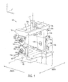
FIG. 1 is a perspective view of a differential motion sensor according to a non-limiting embodiment; -
FIG. 2A is a side view of a differential motion sensor operating in a closed-circuit mode according to a non-limiting embodiment; and -
FIG. 2B illustrates the differential motion sensor ofFIG. 2A operating in an open-circuit mode according to a non-limiting embodiment. - Referring now to
FIG. 1 , adifferential motion sensor 100 is illustrated according to a non-limiting embodiment. Thedifferential motion sensor 100 includes abase 102 and acradle 104 pivotably connected to thebase 102. Thebase 102 includes afirst surface 106, afirst base arm 108a, and asecond base arm 108b. Thebase 102 extends along a first axis (e.g.,. an X-axis) to define length, a second axis (e.g., a Y-axis) perpendicular to the first axis to define a width, and a third axis (e.g., a Z-axis) perpendicular to the first and second axes to define a height. According to a non-limiting embodiment, thebase 102 can be coupled against a surface of a first panel (not shown inFIG. 1 ) as discussed in greater detail below. Thefirst base arm 108a extends from a first side of thebase 102 in the Z-axis direction, and thesecond base arm 108b extends from a second side of thebase 102 opposite the first side in the Z-axis direction. The first side of thebase 102 includes afirst hinge 110a and the second side of thebase 102 includes asecond hinge 110b. Each of the first andsecond hinges 110a/110b pivots about a rotational axis (A) extending along the Y-axis. The first andsecond hinges 110a/110b are both pivotably coupled to thecradle 104 as discussed in greater detail below. - The
cradle 104 includes afirst cradle arm 112a and asecond cradle arm 112b disposed opposite thefirst cradle arm 112a. Each of the first andsecond cradle arms 112a/112b includes a first end and a second end. A surface of thecradle 104 includes a pair ofopposing crossbars 114a/114b extending along the Y-axis and between the first end of the first andsecond cradle arms 112a/112b to define acradle opening 116. The second end of thefirst cradle arm 112a is pivotably connected to thefirst hinge 110a, and the second end of thesecond cradle arm 112b is pivotably connected to thesecond hinge 110b. In this manner, the cradle 104 (and thus the cradle opening 116) is configured to move in the X-axis direction with respect to thebase 102 when the first andsecond cradle arms 112a/112b pivot about the first andsecond hinges 110a/110b. Thecradle opening 116 can receive astriker pin 117 that may be formed against a second panel (not shown inFIG. 1 ) as discussed in greater detail below. - The
base arms 108a/108b each include arespective base recess 118a/118b formed therein, and the cradle arms each include arespective cradle recess 120a/120b formed therein. Thedifferential motion sensor 100 further contains at least one conductive fuse. According to the non-limiting embodiment illustrated inFIG. 1 , a firstconductive fuse 122a and a second conductive fuse 122b are provided to improve reliability and monitoring redundancy (e.g. Channel A and Channel B) of thedifferential motion sensor 100. It is appreciated, however, that thedifferential motion sensor 100 can be formed with only a single conductive fuse. Eachconductive fuse 122a/122b includes acradle portion 124a/124b and abase portion 126a/126b. Thecradle portion 124a/124b is disposed in arespective cradle recess 120a/120b and is supported therein via acradle bolt 128a/128b. Thebase portion 126a/126b is disposed in arespective base recess 118a/118b and is supported therein via abase bolt 130a/130b. Thecradle portion 124a/124b of the fuse and thebase portion 126a/126b of the fuse are conductively connected to each other at afracture region 132a/132b, which inhibits the discharge sensor from pivoting when a force (i.e., a shear force) applied to thefracture region 132a/132b is less than a fracturing force threshold. According to a non-limiting embodiment, thefacture region 132a/132b is interposed between thebase 102 and thecradle 104. - The
differential motion sensor 100 according to the non-limiting embodiment ofFigure 2A is illustrated with a 2:1 cradle ratio. That is, thecradle arms 112a/112b have a length that is twice the length of thebase arms 108a/108b. Accordingly, a pin force of approximately 95 lbs, for example, would shear thefracture regions 132a/132b of the first and secondconductive fuses 122a/122b, which each fracture at approximately 95 lbs. It is appreciated, however, the cradle ratio of thedifferential motion sensor 100 can be varied to provide a lower pin force/longer pin motion necessary to shear thefracture regions 132a/132b, or a higher pin force/shorter pin motion necessary to shear thefracture regions 132a/132b. In other words, the cradle ratio can be adjusted according to a particular design application of the differential motion sensor. If less force (e.g., pin force) is desired to pivot thecradle 104 and sever theconductive fuse 122a/122b, for example, the length of thecradle arms 112a/112b can be increased from twice the length of thebase arms 108a/108b to three-times the length of thebase arms 108a/108b. The pin force (FP) can be calculated according to the equation:
- Fp = the pin force;
- FS = the shear force required to fracture each fuse; and
- R C = the cradle ratio.
- Although the pin force (FP) described in the equation above reflects an embodiment where two
fuses 126a/126b are implemented such that two shear forces (2FS) are considered, it is appreciated that the pin force (FP) may be determined in a similar manner where only a single fuse 126 is implemented and thus a single shear force (FS) is considered. The shear force (FS) necessary to fracture the fuse loaded in shear is typically approximately 58% of the tensile force (FT) necessary to fracture the fuse loaded in tension. Accordingly, at least one embodiment of the disclosure utilizes shear loading to sever the fracture regions 132/132b instead of tensile force (i.e., pulling force in the Z-direction) to provide adifferential motion sensor 100 with increased sensitivity with respect to conventional sensors that operate according to tensile loading. - The first and second
conductive fuses 122a/122b include one or moreconductive terminals 134a/136a and 134b/136b. One or more wires (not shown) can be electrically connected to theterminals 134a/136a and 134b/136b. In this manner, electrical current provided from a power source (not shown) can flow from theterminals 134a/136a and 134b/136b, or vice versa, when thefracture region 132a/132b is conductively connected. - The
differential motion sensor 100 is configured to operate in a first mode (e.g., a closed-circuit mode) and a second mode (e.g., an open-circuit mode) based on the position of thecradle 104 with respect to thebase 102. For example, thedifferential motion sensor 100 is configured to operate in a first mode when thecradle 104 is aligned with thebase 102, and a second mode when thecradle 104 is pivotably displaced (i.e.,. misaligned) with respect to thebase 102. Displacing thecradle 104 with respect to the base 102 causes theconductive fuse 122a/122b to sever in the second mode. - According to a non-limiting embodiment, the
differential motion sensor 100 operates in the first mode when thefracture region 132a/132b is conductively connected (i.e., not severed) such that current flows between thefuse terminals 134a/136a and 134b/136b. The differential motion sensor, however, operates in the second mode when thefracture region 132a/132b is not conductively connected (i.e., severed) such that current prevented from flowing between theterminals 134a/136a and 134b/136b. When the second mode is effected, a control module (not shown) can detect the stoppage of said current flow. In this manner, the control module can determine that a force applied to differential motion between thecradle 104 and thepin 117 has exceeded the threshold thereby severing one or more of thefracture regions 132a/132b and placing the differential motion sensor in the open-circuit mode. - Referring to
Figure 2A , thedifferential motion sensor 100 is illustrated in a closed-circuit mode according to a non-limiting embodiment. In this scenario, thebase 102 is coupled to afirst panel 200. Asecond panel 202 includes astriker pin 117. Thestriker pin 117 includes a first end connected to thesecond panel 202 and an opposing second end that extends into thecradle opening 116. Thepanels striker pin 117 is stably maintained within thecradle opening 116. Thestriker pin 117, therefore, does not apply a force against either the first orsecond crossbars 114a/114b such that thecradle 104 is not forced to pivot. Accordingly, the force threshold is not exceeded and thefracture region 132a/132b remains electrically connected thereby maintaining the differential motion sensor in the closed-circuit mode. - Turning now to
Figure 2B , thedifferential motion sensor 100 is illustrated in an open-circuit mode according to a non-limiting embodiment. In this scenario, thesecond panel 202 is displaced a distance (d) with respect to thefirst panel 200 such that the motions of the first andsecond panels 200/202 are not synchronized. As a result, thestriker pin 117 is displaced in the pivoting direction of the cradle 104 (i.e., the X-axis) and contacts thesecond crossbar 114b, for example, thereby inducing a moment about thehinges 110a/110b which is resisted by the conductive fuses. When the moment exceeds the threshold, thefracture region 132a/132b of the first and/or secondconductive fuses 122a/122b is fractured in shear and thecradle 104 is allowed to pivot further about thehinges 110a/110b and in the X-direction. The severedfracture region 132a/132b, however, disconnects (i.e., stops) current flow between theterminals 134a/136a and/orterminals 134b/136b thereby initiating the open-circuit mode of thedifferential motion sensor 100. In response to detecting the stoppage of current (i.e., the open-circuit mode), the control module determines that the first panel and/or the second panel are displaced. - According to at least one embodiment, the
differential motion sensor 100 provides sense detection along a single axis. That is, the motion of thecradle 104 needed to fracture one or more of thefracture regions 132a/132b is in the X-axis direction, for example, and is independent of the Y-axis direction and the Z-axis direction. As a result, any relative spanwise motions between the surfaces being monitored, in either the Y-axis and/or Z axis directions, has no influence on the forces reacted at the fuse(s) and thereby resulting in a more predictable sensor performance. In addition, since thefracture regions 132a/132b oriented to fail in shear, as opposed to a tension, the necessary force applied by thestriker pin 117 to sever thefracture region 132a/132b is reduced. Accordingly, the possibility of the first andsecond fracture regions 132a/132b remaining dormant (i.e., intact) following a striking force applied by thestriker pin 117 is reduced. - While the invention has been described with reference to an exemplary embodiment or embodiments, it will be understood by those skilled in the art that various changes may be made and equivalents may be substituted for elements thereof without departing from the scope of the invention. In addition, many modifications may be made to adapt a particular situation or material to the teachings of the invention without departing from the essential scope thereof. Also, in the drawings and the description, there have been disclosed exemplary embodiments of the invention and, although specific terms may have been employed, they are unless otherwise stated used in a generic and descriptive sense only and not for purposes of limitation, the scope of the invention therefore not being so limited. Moreover, the use of the terms first, second, etc., do not denote any order or importance, but rather the terms first, second, etc., are used to distinguish one element from another. Furthermore, the use of the terms a, an, etc. do not denote a limitation of quantity, but rather denote the presence of at least one of the referenced item.
Claims (15)
- A differential motion sensor (100), comprising:a base (102) including a first surface extending along a first axis to define a length and a second axis to define a width, and including at least one hinge (110a, 110b) that pivots about a rotational axis extending along the first axis; anda cradle (104) pivotably coupled to the at least one hinge (110a, 110b) and configured to move in a direction of the second axis when pivoting about the hinge (110a, 110b),wherein the differential motion sensor is configured to operate in a first mode when the cradle (104) is aligned with the base (102) and a second mode when the cradle (104) is pivotably displaced with respect to the base (102).
- The differential motion sensor of claim 1, further comprising at least one conductive fuse (122a, 122b) extending along a third axis that is perpendicular to both the first axis and the second axis, the conductive fuse (122a, 122b) configured to sever in response to an applied shear force induced when effecting the second mode.
- The differential motion sensor of claim 2, wherein the conductive fuse (122a, 122b) includes first fuse portion and second fuse portion each extending along the third axis.
- The differential motion sensor of claim 3, wherein the first and second fuse portions are connected to one another at a fracture region (132a, 132b) that is configured to sever when the shear force exceeds a force threshold.
- The differential motion sensor of claim 4, wherein the fracture region (132a, 132b) is interposed between the cradle (104) and the base (102).
- The differential motion sensor of claim 5, wherein the cradle (104) includes a second surface having an opening (116) for receiving a striker pin (117).
- The differential motion sensor of claim 6, wherein the base (102) further comprises:a first base arm (108a) including a first hinge (110a) formed therein and a second base arm (108b) including a second hinge (110b) formed therein in, the first and second base arms (108a, 108b) formed at opposite ends of the base (102) and extending therefrom along the third axis, andwherein the cradle (104) further comprises:a first cradle arm (112a) including a first end coupled to the second surface and a second end pivotably coupled to the first hinge (110a), a second cradle arm (112b) including a first end coupled to the second surface and a second end pivotably coupled to the second hinge (110b).
- The differential motion sensor arm of claim 7, where the first and second base arms (108a, 108b) have a first length, and the first and second cradle arms (112a, 112b) have a second length that is greater than the first length.
- A method of detecting displacement of a first object (200) with respect to a second object (202), the method comprising, comprising:forming a base (102) on the first object (200), the base (102) including a first surface extending along a first axis to define a length and a second axis to define a width, andpivotably connecting a cradle (104) to the base (102) such that the cradle (104) is configured to move in a direction of the second axis; anddetecting that the first and second objects (200, 202) are aligned with respect to one another when the cradle (104) is aligned with the base (102), and detecting that the first and second objects (200, 202) are displaced with respect to one another when the cradle (104) is pivotably displaced with respect to the base (102).
- The method of claim 9, further comprising detecting that the first and second objects (200, 202) are displaced with respect to one another based on a shear force.
- The method of claim 10, further comprising pivoting the cradle (104) about a rotational axis (A) extending along the first axis to induce the shear force.
- The method of 11 further comprising flowing current through at least one conductive fuse (122a, 122b) formed on the differential motion sensor, and detecting that the first and second objects (200, 202) are displaced with respect to one another when the current flow is inhibited.
- The method of claim 12, further comprising forming a first end of a striker pin (117) to the second object (202) and extending a second end of the striker pin (117) into an opening (116) formed in the cradle (104) such that the striker pin (117) applies the shear force on the conductive fuse (122a, 122b) when the first and second objects (200, 202) are displaced with respect to one another.
- The method of claim 13, further comprising severing a fracture region (132a, 132b) of the conductive fuse (122a, 122b) in response to the shear force exceeding a force threshold.
- The method of claim 14, further comprising forming the fracture region (132a, 132b) at an area of the conductive fuse (122a, 122b) located between the cradle (104) and the base (102).
Applications Claiming Priority (1)
| Application Number | Priority Date | Filing Date | Title |
|---|---|---|---|
| US14/510,594 US9638592B2 (en) | 2014-10-09 | 2014-10-09 | Differential motion sensor |
Publications (2)
| Publication Number | Publication Date |
|---|---|
| EP3006344A1 true EP3006344A1 (en) | 2016-04-13 |
| EP3006344B1 EP3006344B1 (en) | 2018-09-19 |
Family
ID=54291177
Family Applications (1)
| Application Number | Title | Priority Date | Filing Date |
|---|---|---|---|
| EP15189101.7A Active EP3006344B1 (en) | 2014-10-09 | 2015-10-09 | Differential motion sensor |
Country Status (4)
| Country | Link |
|---|---|
| US (1) | US9638592B2 (en) |
| EP (1) | EP3006344B1 (en) |
| BR (1) | BR102015025856A2 (en) |
| CA (1) | CA2908147C (en) |
Cited By (1)
| Publication number | Priority date | Publication date | Assignee | Title |
|---|---|---|---|---|
| EP3263463A1 (en) * | 2016-06-28 | 2018-01-03 | Hamilton Sundstrand Corporation | Slat disconnect sensor |
Families Citing this family (1)
| Publication number | Priority date | Publication date | Assignee | Title |
|---|---|---|---|---|
| EP4663539A1 (en) * | 2024-06-13 | 2025-12-17 | AIRBUS Operations GmbH | Failure detection and/or health monitoring system for a high lift system of an aircraft, and method |
Citations (2)
| Publication number | Priority date | Publication date | Assignee | Title |
|---|---|---|---|---|
| EP2368794A2 (en) * | 2010-03-24 | 2011-09-28 | Hamilton Sundstrand Corporation | Aircraft slat disconnect sensor |
| EP2390177A2 (en) * | 2010-05-26 | 2011-11-30 | Airbus Operations Limited | An aircraft slat assembly comprising a plurality of slats |
Family Cites Families (8)
| Publication number | Priority date | Publication date | Assignee | Title |
|---|---|---|---|---|
| US4899600A (en) * | 1981-05-19 | 1990-02-13 | Setra Systems, Inc. | Compact force transducer with mechanical motion amplification |
| US6220545B1 (en) * | 1999-08-06 | 2001-04-24 | Bell Helicopter Textron Inc. | Method and apparatus for sensing preload in a tilt rotor downstop |
| US6466141B1 (en) * | 1999-09-28 | 2002-10-15 | Lucas Industries Limited | Skew detection system |
| US6483436B1 (en) * | 2001-05-21 | 2002-11-19 | Hamilton Sundstrand Corporation | Method and apparatus for sensing skews and disconnects of adjacent movable components |
| US7921729B2 (en) * | 2008-03-10 | 2011-04-12 | Hamilton Sundstrand Corporation | Disconnect sensor |
| US8115649B2 (en) * | 2009-04-30 | 2012-02-14 | The Boeing Company | Slat skew detection system |
| US9102418B2 (en) * | 2010-10-28 | 2015-08-11 | Hamilton Sundstrand Corporation | Cantilevered differential motion sensor and associated frame |
| US20150332881A1 (en) * | 2014-05-19 | 2015-11-19 | Hamilton Sundstrand Corporation | Electromechanical fuse for differential motion sensing |
-
2014
- 2014-10-09 US US14/510,594 patent/US9638592B2/en active Active
-
2015
- 2015-10-08 CA CA2908147A patent/CA2908147C/en active Active
- 2015-10-09 BR BR102015025856A patent/BR102015025856A2/en active Search and Examination
- 2015-10-09 EP EP15189101.7A patent/EP3006344B1/en active Active
Patent Citations (2)
| Publication number | Priority date | Publication date | Assignee | Title |
|---|---|---|---|---|
| EP2368794A2 (en) * | 2010-03-24 | 2011-09-28 | Hamilton Sundstrand Corporation | Aircraft slat disconnect sensor |
| EP2390177A2 (en) * | 2010-05-26 | 2011-11-30 | Airbus Operations Limited | An aircraft slat assembly comprising a plurality of slats |
Cited By (1)
| Publication number | Priority date | Publication date | Assignee | Title |
|---|---|---|---|---|
| EP3263463A1 (en) * | 2016-06-28 | 2018-01-03 | Hamilton Sundstrand Corporation | Slat disconnect sensor |
Also Published As
| Publication number | Publication date |
|---|---|
| US20160103027A1 (en) | 2016-04-14 |
| US9638592B2 (en) | 2017-05-02 |
| CA2908147C (en) | 2022-09-06 |
| EP3006344B1 (en) | 2018-09-19 |
| BR102015025856A2 (en) | 2016-05-24 |
| CA2908147A1 (en) | 2016-04-09 |
Similar Documents
| Publication | Publication Date | Title |
|---|---|---|
| US7921729B2 (en) | Disconnect sensor | |
| JP2020512953A (en) | Uplock device for aircraft | |
| US8820174B2 (en) | Dual threshold sensor for detecting relative movement | |
| US6483436B1 (en) | Method and apparatus for sensing skews and disconnects of adjacent movable components | |
| KR20110061579A (en) | Distributed safety monitoring system with safety loop and how to test the system | |
| EP3006344B1 (en) | Differential motion sensor | |
| EP1957364B1 (en) | Flap comprising a device for error detection of the flap | |
| EP2447161B1 (en) | Cantilevered differential motion sensor and associated frame | |
| US20170038225A1 (en) | Differential motion sensor | |
| US10152855B1 (en) | Wireless tamper system | |
| EP1029784B1 (en) | Detection apparatus | |
| US20040252029A1 (en) | Breaking detector for shear pin | |
| US6707372B2 (en) | Thermal switch containing preflight test feature and fault location detection | |
| EP0173635A1 (en) | Load carrying device | |
| US10059463B2 (en) | Sensor system for a wing panel assembly and method of monitoring a wing panel assembly | |
| EP3581486B1 (en) | Method for detecting a break in a highlift system of an airplane | |
| EP3461739B1 (en) | Retention member monitoring system for slat-flap control lever | |
| US20190047818A1 (en) | Apparatus and method for ground fault detection | |
| US12500049B2 (en) | Emulated voltage-free safety contact | |
| US7557721B2 (en) | On-board thermostat and a system for detecting excess temperature | |
| US10577122B2 (en) | Slat disconnect sensor | |
| AU2018256481B2 (en) | Wireless tamper device | |
| BR102018073475B1 (en) | WIRELESS TAMPER DEVICE AND METHOD FOR DETECTING TAMERING IN A WIRELESS TAMPER DEVICE | |
| PL67915Y1 (en) | Individual responsing detector for protective equipment against falls from a height |
Legal Events
| Date | Code | Title | Description |
|---|---|---|---|
| PUAI | Public reference made under article 153(3) epc to a published international application that has entered the european phase |
Free format text: ORIGINAL CODE: 0009012 |
|
| AK | Designated contracting states |
Kind code of ref document: A1 Designated state(s): AL AT BE BG CH CY CZ DE DK EE ES FI FR GB GR HR HU IE IS IT LI LT LU LV MC MK MT NL NO PL PT RO RS SE SI SK SM TR |
|
| AX | Request for extension of the european patent |
Extension state: BA ME |
|
| 17P | Request for examination filed |
Effective date: 20161012 |
|
| RBV | Designated contracting states (corrected) |
Designated state(s): AL AT BE BG CH CY CZ DE DK EE ES FI FR GB GR HR HU IE IS IT LI LT LU LV MC MK MT NL NO PL PT RO RS SE SI SK SM TR |
|
| STAA | Information on the status of an ep patent application or granted ep patent |
Free format text: STATUS: EXAMINATION IS IN PROGRESS |
|
| 17Q | First examination report despatched |
Effective date: 20170602 |
|
| REG | Reference to a national code |
Ref country code: DE Ref legal event code: R079 Ref document number: 602015016536 Country of ref document: DE Free format text: PREVIOUS MAIN CLASS: B64D0045000000 Ipc: G01B0005000000 |
|
| GRAP | Despatch of communication of intention to grant a patent |
Free format text: ORIGINAL CODE: EPIDOSNIGR1 |
|
| RIC1 | Information provided on ipc code assigned before grant |
Ipc: G01L 5/00 20060101ALI20180305BHEP Ipc: B64D 45/00 20060101ALI20180305BHEP Ipc: G01B 5/14 20060101ALI20180305BHEP Ipc: G01B 5/00 20060101AFI20180305BHEP |
|
| STAA | Information on the status of an ep patent application or granted ep patent |
Free format text: STATUS: GRANT OF PATENT IS INTENDED |
|
| INTG | Intention to grant announced |
Effective date: 20180412 |
|
| GRAS | Grant fee paid |
Free format text: ORIGINAL CODE: EPIDOSNIGR3 |
|
| GRAA | (expected) grant |
Free format text: ORIGINAL CODE: 0009210 |
|
| STAA | Information on the status of an ep patent application or granted ep patent |
Free format text: STATUS: THE PATENT HAS BEEN GRANTED |
|
| AK | Designated contracting states |
Kind code of ref document: B1 Designated state(s): AL AT BE BG CH CY CZ DE DK EE ES FI FR GB GR HR HU IE IS IT LI LT LU LV MC MK MT NL NO PL PT RO RS SE SI SK SM TR |
|
| REG | Reference to a national code |
Ref country code: GB Ref legal event code: FG4D |
|
| REG | Reference to a national code |
Ref country code: CH Ref legal event code: EP |
|
| REG | Reference to a national code |
Ref country code: AT Ref legal event code: REF Ref document number: 1043757 Country of ref document: AT Kind code of ref document: T Effective date: 20181015 |
|
| REG | Reference to a national code |
Ref country code: IE Ref legal event code: FG4D |
|
| REG | Reference to a national code |
Ref country code: FR Ref legal event code: PLFP Year of fee payment: 4 |
|
| REG | Reference to a national code |
Ref country code: DE Ref legal event code: R096 Ref document number: 602015016536 Country of ref document: DE |
|
| REG | Reference to a national code |
Ref country code: NL Ref legal event code: MP Effective date: 20180919 |
|
| PG25 | Lapsed in a contracting state [announced via postgrant information from national office to epo] |
Ref country code: NO Free format text: LAPSE BECAUSE OF FAILURE TO SUBMIT A TRANSLATION OF THE DESCRIPTION OR TO PAY THE FEE WITHIN THE PRESCRIBED TIME-LIMIT Effective date: 20181219 Ref country code: BG Free format text: LAPSE BECAUSE OF FAILURE TO SUBMIT A TRANSLATION OF THE DESCRIPTION OR TO PAY THE FEE WITHIN THE PRESCRIBED TIME-LIMIT Effective date: 20181219 Ref country code: LT Free format text: LAPSE BECAUSE OF FAILURE TO SUBMIT A TRANSLATION OF THE DESCRIPTION OR TO PAY THE FEE WITHIN THE PRESCRIBED TIME-LIMIT Effective date: 20180919 Ref country code: GR Free format text: LAPSE BECAUSE OF FAILURE TO SUBMIT A TRANSLATION OF THE DESCRIPTION OR TO PAY THE FEE WITHIN THE PRESCRIBED TIME-LIMIT Effective date: 20181220 Ref country code: RS Free format text: LAPSE BECAUSE OF FAILURE TO SUBMIT A TRANSLATION OF THE DESCRIPTION OR TO PAY THE FEE WITHIN THE PRESCRIBED TIME-LIMIT Effective date: 20180919 Ref country code: FI Free format text: LAPSE BECAUSE OF FAILURE TO SUBMIT A TRANSLATION OF THE DESCRIPTION OR TO PAY THE FEE WITHIN THE PRESCRIBED TIME-LIMIT Effective date: 20180919 Ref country code: SE Free format text: LAPSE BECAUSE OF FAILURE TO SUBMIT A TRANSLATION OF THE DESCRIPTION OR TO PAY THE FEE WITHIN THE PRESCRIBED TIME-LIMIT Effective date: 20180919 |
|
| REG | Reference to a national code |
Ref country code: LT Ref legal event code: MG4D |
|
| PG25 | Lapsed in a contracting state [announced via postgrant information from national office to epo] |
Ref country code: AL Free format text: LAPSE BECAUSE OF FAILURE TO SUBMIT A TRANSLATION OF THE DESCRIPTION OR TO PAY THE FEE WITHIN THE PRESCRIBED TIME-LIMIT Effective date: 20180919 Ref country code: LV Free format text: LAPSE BECAUSE OF FAILURE TO SUBMIT A TRANSLATION OF THE DESCRIPTION OR TO PAY THE FEE WITHIN THE PRESCRIBED TIME-LIMIT Effective date: 20180919 Ref country code: HR Free format text: LAPSE BECAUSE OF FAILURE TO SUBMIT A TRANSLATION OF THE DESCRIPTION OR TO PAY THE FEE WITHIN THE PRESCRIBED TIME-LIMIT Effective date: 20180919 |
|
| REG | Reference to a national code |
Ref country code: AT Ref legal event code: MK05 Ref document number: 1043757 Country of ref document: AT Kind code of ref document: T Effective date: 20180919 |
|
| PG25 | Lapsed in a contracting state [announced via postgrant information from national office to epo] |
Ref country code: IS Free format text: LAPSE BECAUSE OF FAILURE TO SUBMIT A TRANSLATION OF THE DESCRIPTION OR TO PAY THE FEE WITHIN THE PRESCRIBED TIME-LIMIT Effective date: 20190119 Ref country code: PL Free format text: LAPSE BECAUSE OF FAILURE TO SUBMIT A TRANSLATION OF THE DESCRIPTION OR TO PAY THE FEE WITHIN THE PRESCRIBED TIME-LIMIT Effective date: 20180919 Ref country code: AT Free format text: LAPSE BECAUSE OF FAILURE TO SUBMIT A TRANSLATION OF THE DESCRIPTION OR TO PAY THE FEE WITHIN THE PRESCRIBED TIME-LIMIT Effective date: 20180919 Ref country code: EE Free format text: LAPSE BECAUSE OF FAILURE TO SUBMIT A TRANSLATION OF THE DESCRIPTION OR TO PAY THE FEE WITHIN THE PRESCRIBED TIME-LIMIT Effective date: 20180919 Ref country code: IT Free format text: LAPSE BECAUSE OF FAILURE TO SUBMIT A TRANSLATION OF THE DESCRIPTION OR TO PAY THE FEE WITHIN THE PRESCRIBED TIME-LIMIT Effective date: 20180919 Ref country code: ES Free format text: LAPSE BECAUSE OF FAILURE TO SUBMIT A TRANSLATION OF THE DESCRIPTION OR TO PAY THE FEE WITHIN THE PRESCRIBED TIME-LIMIT Effective date: 20180919 Ref country code: RO Free format text: LAPSE BECAUSE OF FAILURE TO SUBMIT A TRANSLATION OF THE DESCRIPTION OR TO PAY THE FEE WITHIN THE PRESCRIBED TIME-LIMIT Effective date: 20180919 Ref country code: CZ Free format text: LAPSE BECAUSE OF FAILURE TO SUBMIT A TRANSLATION OF THE DESCRIPTION OR TO PAY THE FEE WITHIN THE PRESCRIBED TIME-LIMIT Effective date: 20180919 Ref country code: NL Free format text: LAPSE BECAUSE OF FAILURE TO SUBMIT A TRANSLATION OF THE DESCRIPTION OR TO PAY THE FEE WITHIN THE PRESCRIBED TIME-LIMIT Effective date: 20180919 |
|
| PG25 | Lapsed in a contracting state [announced via postgrant information from national office to epo] |
Ref country code: SM Free format text: LAPSE BECAUSE OF FAILURE TO SUBMIT A TRANSLATION OF THE DESCRIPTION OR TO PAY THE FEE WITHIN THE PRESCRIBED TIME-LIMIT Effective date: 20180919 Ref country code: PT Free format text: LAPSE BECAUSE OF FAILURE TO SUBMIT A TRANSLATION OF THE DESCRIPTION OR TO PAY THE FEE WITHIN THE PRESCRIBED TIME-LIMIT Effective date: 20190119 Ref country code: SK Free format text: LAPSE BECAUSE OF FAILURE TO SUBMIT A TRANSLATION OF THE DESCRIPTION OR TO PAY THE FEE WITHIN THE PRESCRIBED TIME-LIMIT Effective date: 20180919 |
|
| REG | Reference to a national code |
Ref country code: CH Ref legal event code: PL |
|
| REG | Reference to a national code |
Ref country code: DE Ref legal event code: R097 Ref document number: 602015016536 Country of ref document: DE |
|
| REG | Reference to a national code |
Ref country code: BE Ref legal event code: MM Effective date: 20181031 |
|
| PG25 | Lapsed in a contracting state [announced via postgrant information from national office to epo] |
Ref country code: LU Free format text: LAPSE BECAUSE OF NON-PAYMENT OF DUE FEES Effective date: 20181009 |
|
| REG | Reference to a national code |
Ref country code: IE Ref legal event code: MM4A |
|
| PLBE | No opposition filed within time limit |
Free format text: ORIGINAL CODE: 0009261 |
|
| STAA | Information on the status of an ep patent application or granted ep patent |
Free format text: STATUS: NO OPPOSITION FILED WITHIN TIME LIMIT |
|
| PG25 | Lapsed in a contracting state [announced via postgrant information from national office to epo] |
Ref country code: DK Free format text: LAPSE BECAUSE OF FAILURE TO SUBMIT A TRANSLATION OF THE DESCRIPTION OR TO PAY THE FEE WITHIN THE PRESCRIBED TIME-LIMIT Effective date: 20180919 Ref country code: MC Free format text: LAPSE BECAUSE OF FAILURE TO SUBMIT A TRANSLATION OF THE DESCRIPTION OR TO PAY THE FEE WITHIN THE PRESCRIBED TIME-LIMIT Effective date: 20180919 |
|
| 26N | No opposition filed |
Effective date: 20190620 |
|
| PG25 | Lapsed in a contracting state [announced via postgrant information from national office to epo] |
Ref country code: LI Free format text: LAPSE BECAUSE OF NON-PAYMENT OF DUE FEES Effective date: 20181031 Ref country code: BE Free format text: LAPSE BECAUSE OF NON-PAYMENT OF DUE FEES Effective date: 20181031 Ref country code: CH Free format text: LAPSE BECAUSE OF NON-PAYMENT OF DUE FEES Effective date: 20181031 |
|
| PG25 | Lapsed in a contracting state [announced via postgrant information from national office to epo] |
Ref country code: IE Free format text: LAPSE BECAUSE OF NON-PAYMENT OF DUE FEES Effective date: 20181009 Ref country code: SI Free format text: LAPSE BECAUSE OF FAILURE TO SUBMIT A TRANSLATION OF THE DESCRIPTION OR TO PAY THE FEE WITHIN THE PRESCRIBED TIME-LIMIT Effective date: 20180919 |
|
| PG25 | Lapsed in a contracting state [announced via postgrant information from national office to epo] |
Ref country code: MT Free format text: LAPSE BECAUSE OF NON-PAYMENT OF DUE FEES Effective date: 20181009 |
|
| PG25 | Lapsed in a contracting state [announced via postgrant information from national office to epo] |
Ref country code: TR Free format text: LAPSE BECAUSE OF FAILURE TO SUBMIT A TRANSLATION OF THE DESCRIPTION OR TO PAY THE FEE WITHIN THE PRESCRIBED TIME-LIMIT Effective date: 20180919 |
|
| PG25 | Lapsed in a contracting state [announced via postgrant information from national office to epo] |
Ref country code: CY Free format text: LAPSE BECAUSE OF FAILURE TO SUBMIT A TRANSLATION OF THE DESCRIPTION OR TO PAY THE FEE WITHIN THE PRESCRIBED TIME-LIMIT Effective date: 20180919 Ref country code: MK Free format text: LAPSE BECAUSE OF NON-PAYMENT OF DUE FEES Effective date: 20180919 Ref country code: HU Free format text: LAPSE BECAUSE OF FAILURE TO SUBMIT A TRANSLATION OF THE DESCRIPTION OR TO PAY THE FEE WITHIN THE PRESCRIBED TIME-LIMIT; INVALID AB INITIO Effective date: 20151009 |
|
| P01 | Opt-out of the competence of the unified patent court (upc) registered |
Effective date: 20230630 |
|
| PGFP | Annual fee paid to national office [announced via postgrant information from national office to epo] |
Ref country code: DE Payment date: 20251015 Year of fee payment: 11 |
|
| PGFP | Annual fee paid to national office [announced via postgrant information from national office to epo] |
Ref country code: GB Payment date: 20251023 Year of fee payment: 11 |
|
| PGFP | Annual fee paid to national office [announced via postgrant information from national office to epo] |
Ref country code: FR Payment date: 20251028 Year of fee payment: 11 |