EP3006318A1 - Heat-shielding structure for periphery of ignition switch - Google Patents
Heat-shielding structure for periphery of ignition switch Download PDFInfo
- Publication number
- EP3006318A1 EP3006318A1 EP14803467.1A EP14803467A EP3006318A1 EP 3006318 A1 EP3006318 A1 EP 3006318A1 EP 14803467 A EP14803467 A EP 14803467A EP 3006318 A1 EP3006318 A1 EP 3006318A1
- Authority
- EP
- European Patent Office
- Prior art keywords
- ignition switch
- heat shielding
- shielding member
- air cleaner
- heat
- Prior art date
- Legal status (The legal status is an assumption and is not a legal conclusion. Google has not performed a legal analysis and makes no representation as to the accuracy of the status listed.)
- Granted
Links
Images




Classifications
-
- B—PERFORMING OPERATIONS; TRANSPORTING
- B62—LAND VEHICLES FOR TRAVELLING OTHERWISE THAN ON RAILS
- B62J—CYCLE SADDLES OR SEATS; AUXILIARY DEVICES OR ACCESSORIES SPECIALLY ADAPTED TO CYCLES AND NOT OTHERWISE PROVIDED FOR, e.g. ARTICLE CARRIERS OR CYCLE PROTECTORS
- B62J23/00—Other protectors specially adapted for cycles
-
- B—PERFORMING OPERATIONS; TRANSPORTING
- B62—LAND VEHICLES FOR TRAVELLING OTHERWISE THAN ON RAILS
- B62K—CYCLES; CYCLE FRAMES; CYCLE STEERING DEVICES; RIDER-OPERATED TERMINAL CONTROLS SPECIALLY ADAPTED FOR CYCLES; CYCLE AXLE SUSPENSIONS; CYCLE SIDECARS, FORECARS, OR THE LIKE
- B62K11/00—Motorcycles, engine-assisted cycles or motor scooters with one or two wheels
- B62K11/02—Frames
- B62K11/04—Frames characterised by the engine being between front and rear wheels
-
- F—MECHANICAL ENGINEERING; LIGHTING; HEATING; WEAPONS; BLASTING
- F02—COMBUSTION ENGINES; HOT-GAS OR COMBUSTION-PRODUCT ENGINE PLANTS
- F02B—INTERNAL-COMBUSTION PISTON ENGINES; COMBUSTION ENGINES IN GENERAL
- F02B61/00—Adaptations of engines for driving vehicles or for driving propellers; Combinations of engines with gearing
- F02B61/02—Adaptations of engines for driving vehicles or for driving propellers; Combinations of engines with gearing for driving cycles
-
- F—MECHANICAL ENGINEERING; LIGHTING; HEATING; WEAPONS; BLASTING
- F02—COMBUSTION ENGINES; HOT-GAS OR COMBUSTION-PRODUCT ENGINE PLANTS
- F02B—INTERNAL-COMBUSTION PISTON ENGINES; COMBUSTION ENGINES IN GENERAL
- F02B77/00—Component parts, details or accessories, not otherwise provided for
- F02B77/11—Thermal or acoustic insulation
Definitions
- the present invention relates to an improvement in and of a heat shielding structure in the neighborhood of an ignition switch in a motorcycle.
- Patent Document 1 JP Laid-open Patent Publication No. S63-112292
- the ignition switch is disposed above the combustion engine, the ignition switch is exposed to the heat.
- the present invention has for its object to provide a structure that inexpensively enables a heat shielding in the neighborhood of the ignition switch by adding a simple structure.
- the present invention provides a heat shielding structure around an ignition switch, which includes: a cowling to cover an outer side of at least a front portion of a combustion engine of a motorcycle; an ignition switch disposed above the combustion engine and in the rearward neighborhood of a head pipe; and a first heat shielding member configured to cover at least a rear face and opposite side faces of the ignition switch to shield a heat raising upwardly from the combustion engine.
- the cowling even though, thanks to the use of the cowling, a substantial amount of heat emanating from the combustion engine raises, at least the rear and opposite side faces of the ignition switch tending to be exposed to the raising heat are protected by the first heat shielding member. Therefore, reduction in function brought about by the heating of the ignition switch to the elevated temperature is prevented.
- the ignition switch may be disposed above a main frame, in which case the main frame has a front portion to which the head pipe is connected, and a part of the first heat shielding member seals between the ignition switch and the main frame.
- the ignition switch may be disposed above the main frame, in which case the main frame has a front portion to which the head pipe is connected, and an air cleaner is provided rearwardly of the ignition switch.
- a gap between the ignition switch and the air cleaner and a gap between the main frame and the air cleaner may be covered by a second heat shielding member.
- a front portion of a side surface of the air cleaner may be covered by the cowling, in which case the second heat shielding member is interposed between the air cleaner and the cowling.
- the first heat shielding member may be engaged in a recess defined in a front end portion of the second heat shielding member.
- a sub intake port forming a part of an intake port may be provided in a front portion of the air cleaner so as to exposed to the outside, in which case the second heat shielding member is positioned above the sub intake port. According to this structural feature, the ingress of rain water into the sub intake port of the air cleaner can be avoided by the second heat shielding member.
- the first and second heat shielding member may be made of a sponge material. Since the sponge material is lightweight, it can be easily fitted to a predetermined side without giving an additional weight loading to the motorcycle.
- FIG. 1 illustrates a schematic side view of a motorcycle embodying the preferred embodiment of the present invention.
- the illustrated motorcycle includes a vehicle body frame structure FR including a main frame 1, forming a front half portion thereof, and a rear frame 2 connected with a rear portion of the main frame 1 and forming a rear half portion of the vehicle frame structure FR.
- a head pipe 3 is fitted to a front end of the main frame 1, and an upper bracket 4 and an under bracket 5 are fitted to a steering shaft (not shown) that is rotatably inserted in the head pipe 3.
- a front fork 8 is supported by the upper bracket 4 and the under bracket 5 and a front wheel 9 is supported by at a lower end portion of the front fork 8.
- the upper bracket 4 at an upper end portion of the front fork 8 has a handlebar 10 fitted thereto.
- the main frame 1 has a rear end portion provided with a swingarm bracket 11, and a swingarm 12 is supported by the swingarm bracket 11 for swinging movement up and down about a pivot pin 13 that is inserted in a front end portion thereof.
- This swingarm 12 has a rear end portion supporting a rear wheel 14.
- a combustion engine E is supported by a lower portion of the main frame 1, and this combustion engine E drives the rear wheel 14 through a transmission mechanism (not shown) such as, for example, a substantially endless chain.
- the combustion engine E employed in the practice of this embodiment is in the form of, for example, a water cooled multi-cylinder combustion engine and, therefore, a radiator 15 for dissipating heat of a cooling liquid is disposed forwardly of the combustion engine E.
- a rider's seat 22 is supported on the rear frame 2, and a fuel tank 18 made of a metallic material is fitted on an upper portion of the main frame 1, that is, on a vehicle upper portion and between the handlebar 10 and the rider's seat 22.
- a region below a rear portion of the fuel tank 18 and, also, below the rider's seat 22 is covered by a side covering 17 from a lateral side
- a vehicle body front portion has mounted thereon a pair of left and right side fairing (cowling) 30, 30, made of a resinous material.
- the side fairing 30 includes a cowl main body 30a, covering a region from a lateral side of a front portion of the combustion engine E to a lateral side of a lower portion thereof, and a tank covering 30b connected with an upper portion of the cowl main body 30a and covering a front portion of the fuel tank 18 from a lateral side.
- a large sized front cowl including a front cowl and a headlamp unit 23, as shown by the double dotted line, which is large enough to cover a region ranging from the front portion of the vehicle body to a lateral side of the combustion engine E may be employed.
- the side fairing 30 and the front cowl 25 are a sort of cowling (those side and front cowls being collectively referred to as "cowling" or "fairing") and cover a lateral side of at least the front portion of the combustion engine E. Accordingly, heat evolved in the combustion engine E is rarely dissipated laterally and a major quantity of the heat is dissipated upwards.
- the headlamp unit 23 referred to above is mounted on the upper bracket 4 and the under bracket 5.
- An ignition switch 16 is disposed intermediate between the head pipe 3 and the fuel tank 18, and an air cleaner 36 shown in Fig. 2 is disposed rearwardly of the ignition switch 16.
- the ignition switch 16 is positioned in the vicinity of the rear of the head pipe 3, and the air cleaner 36 is positioned in the vicinity of the rear of the ignition switch 16.
- the main frame 1 includes a pair of left and right main frame piece 1a and 1b, and the air cleaner 36 referred to above is disposed intermediate between those frame pieces 1a and 1b.
- the air cleaner 36 has a front portion supported by the main frame 1 by means of a connecting member 43 such as, for example, a bolt, and also has a rear portion supported by a throttle body 44 of the combustion engine E.
- the ignition switch 16 is fixed to the main frame 1 by inserting a bolt (not shown) into a bolt insertion hole 27 and threading the bolt into a threaded hole defined in the main frame 1.
- the tank covering 30b forming an upper portion of the side fairing 30 is supported by the ignition switch 16 by means of a connecting member 28.
- the cowl main body 30a of the side fairing 30 is supported by the main frame 1 and the combustion engine E, both shown in Fig. 1 .
- a gap exists between the pair of the side fairings 30 and 30, and an incoming wind is introduced through this gap towards a front surface of the combustion engine E.
- the side fairing 30 covers a region forward of a side portion of the combustion engine E, a front portion of a side surface of the air cleaner 36 and a region below that front portion of the side surface of the air cleaner 36. Accordingly, a portion of the heat 100 emanating from the combustion engine E is prevented from flowing rearward by the side fairing 30 and, therefore, flows upwards from a side portion of the combustion engine E towards a side portion of the air cleaner 36.
- a first heat shielding member 35 is mounted on the ignition switch 16 and, as will be described in detail later, the first heat shielding member 35 serves to accomplish heat shielding in the vicinity of the ignition switch 16.
- a gap between the ignition switch 16 and a front end portion of the air cleaner 36 and a gap between the front portion of the main frame 1 and a front portion side face of the air cleaner 36 are covered from above by a second heat shielding member 37.
- the second heat shielding member 37 is interposed between the air cleaner 36 and the side fairing 30, and seals a gap therebetween.
- a third heat shielding member 38 seals a gap between a rear outer portion of the second heat shielding member 37 and the side fairing 30. It is, however, to be noted that the use of this third heat shielding member 38 is not essential in the practice of the present invention and may therefore be dispensed with.
- Fig. 4 illustrates a rear view of the neighborhood of the ignition switch as viewed from rear.
- the second heat shielding member 37 is fixed to respective upper surfaces of the main frame pieces 1a and 1b by means of a fixing unit such as, for example, a double sided adhesive tape or a bonding agent.
- This second heat shielding member 37 has a front end portion held in contact with a rear surface of the first heat shielding member 35.
- An intake air delivery port 39 opening rearwardly is formed in a vehicle widthwise direction intermediate portion of the front portion of the main frame 1, and an incoming wind, introduced through the intake air introducing port 40 (as shown in Fig. 2 ) opening, in an outer side face of the main frame 1, is guided towards the intake air delivery port 39 through an intake air passage defined in the interior of the main frame 1.
- the air cleaner 36 shown in Fig. 2 has a main air intake port 41 fluidly connected with the intake air delivery port 39 in the main frame 1.
- a sub intake port 42 for sucking an additional air protrudes downwardly from the air cleaner 36 and is exposed to the outside.
- the main intake port 41 and the sub intake port 42 are positioned at a vehicle widthwise direction intermediate portion of the air cleaner 36.
- Fig. 5 illustrates a schematic side view showing, on an enlarged scale, the neighborhood of the ignition switch 16.
- rear and side faces of the ignition switch 16 are covered by a major portion of the first heat shielding member 35, and a sealing piece 35D, which forms a part of the first heat shielding member 35, seals between a lower surface of the ignition switch 16 and an upper surface of the main frame 1.
- a gap between the ignition switch 16 and the air cleaner 36 and a gap between the main frame 1 and the air cleaner 36 are covered by the second heat shielding member 37.
- the first heat shielding member 35 includes three parts including member pieces 35A, 35B and 35C, and each of the member pieces 35A to 35C has an inner side formed with recesses 35a, 35b and 35c that cooperate with each other to accommodate the ignition switch 16.
- the ignition switch 16 is, as shown by the double dotted line, held by those recesses 35a, 35b and 35c with the rear and opposite side faces of such ignition switch 16 consequently covered thereby.
- the first heat shielding member 35 may not be necessarily comprised of the three parts and may be comprised of one part, two parts or four or more parts.
- This first heat shielding member 35 is made of a resin-made, somewhat hard sponge material, and therefore, is lightweight and excellent in heat shielding property. However, it is noted that any other material, if having an equivalent function, may be used for the first heat shielding member 35.
- the second heat shielding member 37 is comprised of a single part. Specifically, the second heat shielding member 37 has a front portion formed with a recess 37a in which rear face and opposite side faces of the first heat shielding member 35 are engaged, and also has an inner surface of a rear portion formed with a recess 37b with which a front portion outer peripheral surface of the air cleaner 36 contacts. Also, the second heat shielding member 37 is formed with a recess 37c, as best shown in Fig. 7 , which follows the shape of the connecting member 43 used to fix the air cleaner 36 to the main frame 1 shown in Fig. 3 .
- Each of the second heat shielding member 37 and the third heat shielding member 38 is made of a material similar to that used to form the first heat shielding member 35.
- the second heat shielding member 37 may be fixed to the air cleaner 36, shown in Fig. 3 , by means of a fixing unit such as, for example, a double sided adhesive tape or a bonding agent, and the third heat shielding member 38 may be fixed to the side fairing 30 by means of a similar fixing unit.
- the ignition switch 16 is disposed above the main frame 1 connected at its front with the head pipe 3, and the sealing piece 35D which forms a part of the first heat shielding member 35 seals between the ignition switch 16 and the main frame 1. Accordingly, heating of the ignition switch 16 to the elevated temperature as a result of passage of the heat 100 of the combustion engine E between the lower surface of the ignition switch 16 and the upper surface of the main frame 1 is avoided.
- the air cleaner 36 is disposed rearwardly of the ignition switch 16 shown in Fig. 3 , and the gap between the ignition switch 16 and the air cleaner 36 and the gap between the main frame 1 and the air cleaner 36 are covered by the second heat shielding member 37. Accordingly, the heat raising from the combustion engine E can be prevented, by the second heat shielding member 37, from flowing from the lower surface of the air cleaner 36 towards the ignition switch 16 side. Therefore, the heat shielding in the vicinity of the ignition switch 16 is further effectively accomplished.
- the front portion of the side surface of the air cleaner 36 is covered by the pair of the left and right side fairings 30 and 30, and the second heat shielding member 37 intervenes between the side fairing 30 and the air cleaner 36. Accordingly, the heat 10 from the combustion engine E flowing towards the neighborhood of the ignition switch 16 around the gap between the side fairing 30 and the air cleaner 36 can be effectively prevented by the second heat shielding member 37.
- first heat shielding member 35 shown in Fig. 5 is engaged in the recess 37a defined in the front end portion of the second heat shielding member 37, and therefore, positioning between the first heat shielding member 35 and the second heat shielding member 37 is accomplished accurately.
- the gap existing between the first and second heat shielding members 35 and 37 can be eliminated and, therefore, the heat shielding effect around the ignition switch 16 is further enhanced.
- the front portion of the air cleaner 36 shown in Fig. 2 is provided with the sub intake port 42, forming a portion of the intake port, so as to be exposed to the outside and the second heat shielding ember 37 is positioned above the sub intake port 42. Accordingly, flow of rain water into the sub intake port 42 can be prevented by the second heat shielding member 37.
- each of the first and second heat shielding members 35 and 37 is made of the sponge material, they can be easily fitted to predetermined site without adding a weight loading to the motorcycle.
Landscapes
- Engineering & Computer Science (AREA)
- Mechanical Engineering (AREA)
- Chemical & Material Sciences (AREA)
- Combustion & Propulsion (AREA)
- General Engineering & Computer Science (AREA)
- Physics & Mathematics (AREA)
- Acoustics & Sound (AREA)
- Automatic Cycles, And Cycles In General (AREA)
- Exhaust Silencers (AREA)
Abstract
Description
- This application is based on and claims Convention priority to
Japanese patent application No. 2013-111700, filed May 28, 2013 - The present invention relates to an improvement in and of a heat shielding structure in the neighborhood of an ignition switch in a motorcycle.
- Hitherto, arrangement has been employed in which an ignition switch in a motorcycle is disposed in the rearward neighborhood of a head pipe. In such case, the ignition switch comes to be positioned above a combustion engine. In this respect, see the
patent document 1 listed below. When a cowling is mounted on such a motorcycle, as a result that dissipation of heat generated by the combustion engine is hampered by the cowling, a major quantity of the heat flows upwardly. - Patent Document 1:
JP Laid-open Patent Publication No. S63-112292 - Accordingly, if the ignition switch is disposed above the combustion engine, the ignition switch is exposed to the heat.
- In view of the foregoing, the present invention has for its object to provide a structure that inexpensively enables a heat shielding in the neighborhood of the ignition switch by adding a simple structure.
- In order to accomplish the foregoing object, the present invention provides a heat shielding structure around an ignition switch, which includes: a cowling to cover an outer side of at least a front portion of a combustion engine of a motorcycle; an ignition switch disposed above the combustion engine and in the rearward neighborhood of a head pipe; and a first heat shielding member configured to cover at least a rear face and opposite side faces of the ignition switch to shield a heat raising upwardly from the combustion engine.
- According to the present invention, even though, thanks to the use of the cowling, a substantial amount of heat emanating from the combustion engine raises, at least the rear and opposite side faces of the ignition switch tending to be exposed to the raising heat are protected by the first heat shielding member. Therefore, reduction in function brought about by the heating of the ignition switch to the elevated temperature is prevented.
- In a preferred embodiment of the present invention, the ignition switch may be disposed above a main frame, in which case the main frame has a front portion to which the head pipe is connected, and a part of the first heat shielding member seals between the ignition switch and the main frame. According to this structural feature, with between the lower surface of the ignition switch and the upper surface of the main surface, the heating of the ignition switch to the elevated temperature consequent upon passage of the heat of the combustion engine therebetween can be avoided.
- In another preferred embodiment of the present invention, the ignition switch may be disposed above the main frame, in which case the main frame has a front portion to which the head pipe is connected, and an air cleaner is provided rearwardly of the ignition switch. In such case, a gap between the ignition switch and the air cleaner and a gap between the main frame and the air cleaner may be covered by a second heat shielding member. According to this structural feature, the heat raising from the combustion engine and tending to flow from a lower surface of the air cleaner towards an ignition switch side can be inhibited by the second heat shielding member. Therefore, the heat shielding in the neighborhood of the ignition switch is further effectively accomplished.
- In a further preferred embodiment of the present invention, a front portion of a side surface of the air cleaner may be covered by the cowling, in which case the second heat shielding member is interposed between the air cleaner and the cowling. According to this structural feature, the heat that emanates from the combustion engine and flows towards the neighborhood of the ignition switch around and from the gap between the cowling and the air cleaner can be effectively inhibited by the second heat shielding member.
- In a still further preferred embodiment of the present invention, the first heat shielding member may be engaged in a recess defined in a front end portion of the second heat shielding member. According to this structural feature, since the positioning between the first heat shielding member and the second heat shielding member is accomplished accurately, the gap intervening therebetween can be eliminated. Therefore, the heat shielding effect in the vicinity of the ignition switch is further enhanced.
- In a yet further preferred embodiment of the present invention, a sub intake port forming a part of an intake port may be provided in a front portion of the air cleaner so as to exposed to the outside, in which case the second heat shielding member is positioned above the sub intake port. According to this structural feature, the ingress of rain water into the sub intake port of the air cleaner can be avoided by the second heat shielding member.
- In a still yet further preferred embodiment of the present invention, the first and second heat shielding member may be made of a sponge material. Since the sponge material is lightweight, it can be easily fitted to a predetermined side without giving an additional weight loading to the motorcycle.
- Any combination of at least two constructions, disclosed in the appended claims and/or the specification and/or the accompanying drawings should be construed as included within the scope of the present invention. In particular, any combination of two or more of the appended claims should be equally construed as included within the scope of the present invention.
- In any event, the present invention will become more clearly understood from the following description of preferred embodiments thereof, when taken in conjunction with the accompanying drawings. However, the embodiments and the drawings are given only for the purpose of illustration and explanation, and are not to be taken as limiting the scope of the present invention in any way whatsoever, which scope is to be determined by the appended claims. In the accompanying drawings, like reference numerals are used to denote like parts throughout the several views, and:
-
Fig. 1 is a schematic side view of a motorcycle having employed therein a heat shielding structure which is designed in accordance with a preferred embodiment of the present invention; -
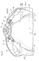
Fig. 2 is a schematic side view showing, on an enlarged scale, the neighborhood of the ignition switch; -
Fig. 3 is a perspective view showing the neighborhood of the ignition switch as viewed from above in a direction diagonally rearwardly thereof; -
Fig. 4 is a schematic rear view showing the neighborhood of the ignition switch as viewed from rear; -
Fig. 5 is a schematic side view showing, on a further enlarged scale, showing the neighborhood of the ignition switch; -
Fig. 6 is a perspective view showing a first heat shielding member; and -
Fig. 7 s a perspective view showing a second heat shielding member. - A preferred embodiment of the present invention will be hereinafter discussed in detail with particular reference to the accompanying drawings. In particular,
Fig. 1 illustrates a schematic side view of a motorcycle embodying the preferred embodiment of the present invention. The illustrated motorcycle includes a vehicle body frame structure FR including amain frame 1, forming a front half portion thereof, and arear frame 2 connected with a rear portion of themain frame 1 and forming a rear half portion of the vehicle frame structure FR. Ahead pipe 3 is fitted to a front end of themain frame 1, and an upper bracket 4 and an under bracket 5 are fitted to a steering shaft (not shown) that is rotatably inserted in thehead pipe 3. A front fork 8 is supported by the upper bracket 4 and the under bracket 5 and afront wheel 9 is supported by at a lower end portion of the front fork 8. The upper bracket 4 at an upper end portion of the front fork 8 has ahandlebar 10 fitted thereto. - The
main frame 1 has a rear end portion provided with aswingarm bracket 11, and aswingarm 12 is supported by theswingarm bracket 11 for swinging movement up and down about apivot pin 13 that is inserted in a front end portion thereof. Thisswingarm 12 has a rear end portion supporting arear wheel 14. A combustion engine E is supported by a lower portion of themain frame 1, and this combustion engine E drives therear wheel 14 through a transmission mechanism (not shown) such as, for example, a substantially endless chain. The combustion engine E employed in the practice of this embodiment is in the form of, for example, a water cooled multi-cylinder combustion engine and, therefore, a radiator 15 for dissipating heat of a cooling liquid is disposed forwardly of the combustion engine E. - A rider's
seat 22 is supported on therear frame 2, and afuel tank 18 made of a metallic material is fitted on an upper portion of themain frame 1, that is, on a vehicle upper portion and between thehandlebar 10 and the rider'sseat 22. A region below a rear portion of thefuel tank 18 and, also, below the rider'sseat 22 is covered by a side covering 17 from a lateral side A vehicle body front portion has mounted thereon a pair of left and right side fairing (cowling) 30, 30, made of a resinous material. Theside fairing 30 includes a cowlmain body 30a, covering a region from a lateral side of a front portion of the combustion engine E to a lateral side of a lower portion thereof, and a tank covering 30b connected with an upper portion of the cowlmain body 30a and covering a front portion of thefuel tank 18 from a lateral side. - It is to be noted that in place of the side fairing 30, a large sized front cowl including a front cowl and a
headlamp unit 23, as shown by the double dotted line, which is large enough to cover a region ranging from the front portion of the vehicle body to a lateral side of the combustion engine E, may be employed. The side fairing 30 and thefront cowl 25 are a sort of cowling (those side and front cowls being collectively referred to as "cowling" or "fairing") and cover a lateral side of at least the front portion of the combustion engine E. Accordingly, heat evolved in the combustion engine E is rarely dissipated laterally and a major quantity of the heat is dissipated upwards. - The
headlamp unit 23 referred to above is mounted on the upper bracket 4 and the under bracket 5. Anignition switch 16 is disposed intermediate between thehead pipe 3 and thefuel tank 18, and anair cleaner 36 shown inFig. 2 is disposed rearwardly of theignition switch 16. - The
ignition switch 16 is positioned in the vicinity of the rear of thehead pipe 3, and theair cleaner 36 is positioned in the vicinity of the rear of theignition switch 16. As shown inFig. 3 , themain frame 1 includes a pair of left and rightmain frame piece air cleaner 36 referred to above is disposed intermediate between thoseframe pieces air cleaner 36 has a front portion supported by themain frame 1 by means of a connectingmember 43 such as, for example, a bolt, and also has a rear portion supported by athrottle body 44 of the combustion engine E. - The
ignition switch 16 is fixed to themain frame 1 by inserting a bolt (not shown) into abolt insertion hole 27 and threading the bolt into a threaded hole defined in themain frame 1. The tank covering 30b forming an upper portion of the side fairing 30 is supported by theignition switch 16 by means of a connectingmember 28. The cowlmain body 30a of the side fairing 30 is supported by themain frame 1 and the combustion engine E, both shown inFig. 1 . - As shown by the broken line in
Fig. 3 , a gap exists between the pair of theside fairings air cleaner 36 and a region below that front portion of the side surface of theair cleaner 36. Accordingly, a portion of theheat 100 emanating from the combustion engine E is prevented from flowing rearward by the side fairing 30 and, therefore, flows upwards from a side portion of the combustion engine E towards a side portion of theair cleaner 36. - A first
heat shielding member 35 is mounted on theignition switch 16 and, as will be described in detail later, the firstheat shielding member 35 serves to accomplish heat shielding in the vicinity of theignition switch 16. A gap between theignition switch 16 and a front end portion of theair cleaner 36 and a gap between the front portion of themain frame 1 and a front portion side face of theair cleaner 36 are covered from above by a secondheat shielding member 37. The secondheat shielding member 37 is interposed between theair cleaner 36 and the side fairing 30, and seals a gap therebetween. A thirdheat shielding member 38 seals a gap between a rear outer portion of the secondheat shielding member 37 and theside fairing 30. It is, however, to be noted that the use of this thirdheat shielding member 38 is not essential in the practice of the present invention and may therefore be dispensed with. -
Fig. 4 illustrates a rear view of the neighborhood of the ignition switch as viewed from rear. As shown inFig. 4 , the secondheat shielding member 37 is fixed to respective upper surfaces of themain frame pieces heat shielding member 37 has a front end portion held in contact with a rear surface of the firstheat shielding member 35. An intakeair delivery port 39 opening rearwardly is formed in a vehicle widthwise direction intermediate portion of the front portion of themain frame 1, and an incoming wind, introduced through the intake air introducing port 40 (as shown inFig. 2 ) opening, in an outer side face of themain frame 1, is guided towards the intakeair delivery port 39 through an intake air passage defined in the interior of themain frame 1. - The
air cleaner 36 shown inFig. 2 has a mainair intake port 41 fluidly connected with the intakeair delivery port 39 in themain frame 1. In continuation with a lower portion of this mainair intake port 41, asub intake port 42 for sucking an additional air protrudes downwardly from theair cleaner 36 and is exposed to the outside. Themain intake port 41 and thesub intake port 42 are positioned at a vehicle widthwise direction intermediate portion of theair cleaner 36. -
Fig. 5 illustrates a schematic side view showing, on an enlarged scale, the neighborhood of theignition switch 16. As shown inFig. 5 , rear and side faces of theignition switch 16 are covered by a major portion of the firstheat shielding member 35, and asealing piece 35D, which forms a part of the firstheat shielding member 35, seals between a lower surface of theignition switch 16 and an upper surface of themain frame 1. A gap between theignition switch 16 and theair cleaner 36 and a gap between themain frame 1 and theair cleaner 36 are covered by the secondheat shielding member 37. - As shown in
Fig. 6 , the firstheat shielding member 35 referred to above includes three parts includingmember pieces member pieces 35A to 35C has an inner side formed withrecesses ignition switch 16. Theignition switch 16 is, as shown by the double dotted line, held by thoserecesses such ignition switch 16 consequently covered thereby. It is to be noted that the firstheat shielding member 35 may not be necessarily comprised of the three parts and may be comprised of one part, two parts or four or more parts. This firstheat shielding member 35 is made of a resin-made, somewhat hard sponge material, and therefore, is lightweight and excellent in heat shielding property. However, it is noted that any other material, if having an equivalent function, may be used for the firstheat shielding member 35. - As shown in
Fig. 7 , the secondheat shielding member 37 is comprised of a single part. Specifically, the secondheat shielding member 37 has a front portion formed with arecess 37a in which rear face and opposite side faces of the firstheat shielding member 35 are engaged, and also has an inner surface of a rear portion formed with arecess 37b with which a front portion outer peripheral surface of theair cleaner 36 contacts. Also, the secondheat shielding member 37 is formed with arecess 37c, as best shown inFig. 7 , which follows the shape of the connectingmember 43 used to fix theair cleaner 36 to themain frame 1 shown inFig. 3 . Each of the secondheat shielding member 37 and the thirdheat shielding member 38 is made of a material similar to that used to form the firstheat shielding member 35. The secondheat shielding member 37 may be fixed to theair cleaner 36, shown inFig. 3 , by means of a fixing unit such as, for example, a double sided adhesive tape or a bonding agent, and the thirdheat shielding member 38 may be fixed to the side fairing 30 by means of a similar fixing unit. - In the configuration described hereinabove, although thanks to the presence of the side fairing 30 as shown in
Fig. 1 the substantial amount of heat evolved by the combustion engine E raises, at least the rear and opposite side faces of theignition switch 16 shown inFig. 5 are protected by the firstheat shielding member 35, and therefore, reduction in function brought about by the heating of the ignition switch to the elevated temperature is prevented. - Also, the
ignition switch 16 is disposed above themain frame 1 connected at its front with thehead pipe 3, and thesealing piece 35D which forms a part of the firstheat shielding member 35 seals between theignition switch 16 and themain frame 1. Accordingly, heating of theignition switch 16 to the elevated temperature as a result of passage of theheat 100 of the combustion engine E between the lower surface of theignition switch 16 and the upper surface of themain frame 1 is avoided. - The
air cleaner 36 is disposed rearwardly of theignition switch 16 shown inFig. 3 , and the gap between theignition switch 16 and theair cleaner 36 and the gap between themain frame 1 and theair cleaner 36 are covered by the secondheat shielding member 37. Accordingly, the heat raising from the combustion engine E can be prevented, by the secondheat shielding member 37, from flowing from the lower surface of theair cleaner 36 towards theignition switch 16 side. Therefore, the heat shielding in the vicinity of theignition switch 16 is further effectively accomplished. - Also, the front portion of the side surface of the
air cleaner 36 is covered by the pair of the left andright side fairings heat shielding member 37 intervenes between the side fairing 30 and theair cleaner 36. Accordingly, theheat 10 from the combustion engine E flowing towards the neighborhood of theignition switch 16 around the gap between the side fairing 30 and theair cleaner 36 can be effectively prevented by the secondheat shielding member 37. - Moreover, the first
heat shielding member 35 shown inFig. 5 is engaged in therecess 37a defined in the front end portion of the secondheat shielding member 37, and therefore, positioning between the firstheat shielding member 35 and the secondheat shielding member 37 is accomplished accurately. As a result thereof, the gap existing between the first and secondheat shielding members ignition switch 16 is further enhanced. - In addition, the front portion of the
air cleaner 36 shown inFig. 2 is provided with thesub intake port 42, forming a portion of the intake port, so as to be exposed to the outside and the secondheat shielding ember 37 is positioned above thesub intake port 42. Accordingly, flow of rain water into thesub intake port 42 can be prevented by the secondheat shielding member 37. - Since each of the first and second
heat shielding members - Although the present invention has been fully described in connection with the preferred embodiments thereof with reference to the accompanying drawings which are used only for the purpose of illustration, those skilled in the art will readily conceive numerous changes and modifications within the framework of obviousness upon the reading of the specification herein presented of the present invention. Accordingly, such changes and modifications are, unless they depart from the scope of the present invention as delivered from the claims annexed hereto, to be construed as included therein.
-
- 1 ...... Main frame
- 3 ...... Head pipe
- 16 ...... Ignition switch
- 30 ...... Side fairing (Cowling)
- 35 ...... First heat shielding member
- 35D ...... Part of the first heat shielding member (Sealing piece)
- 36 ...... Air cleaner
- 37 ...... Second heat shielding member
- 38 ...... Third heat shielding member
- 100 ...... Heat
- E ...... Combustion engine
Claims (7)
- A heat shielding structure around an ignition switch which comprises:a cowling to cover an outer side of at least a front portion of a combustion engine of a motorcycle;an ignition switch disposed above the combustion engine and in the rearward neighborhood of a head pipe; anda first heat shielding member configured to cover at least a rear face and opposite side faces of the ignition switch to shield a heat raising upwardly from the combustion engine.
- The heat shielding structure around the ignition switch as claimed in claim 1, in which:the ignition switch is disposed above a main frame having a front portion to which the head pipe is connected; anda part of the first heat shielding member seals between the ignition switch and the main frame.
- The heat shielding structure around the ignition switch as claimed in claim 1 or 2, in which the ignition switch is disposed above the main frame having a front portion to which the head pipe is connected, and an air cleaner is provided rearwardly of the ignition switch,
further comprising a second heat shielding member configured to cover a gap between the ignition switch and the air cleaner and a gap between the main frame and the air cleaner. - The heat shielding structure around the ignition switch as claimed in claim 3, in which a front portion of a side surface of the air cleaner is covered by the cowling, and the second heat shielding member is interposed between the air cleaner and the cowling.
- The heat shielding structure around the ignition switch as claimed in claim 3 or 4, in which the first heat shielding member is engaged in a recess defined in a front end portion of the second heat shielding member.
- The heat shielding structure around the ignition switch as claimed in any one of claims 3 to 5, in which the air cleaner further comprises a sub intake port forming a part of an intake port, the sub intake port being provided in a front portion of the air cleaner so as to exposed to the outside; and
the second heat shielding member is positioned above the sub intake port. - The heat shielding structure around the ignition switch as claimed in any one of claims 3 to 6, in which the first and second heat shielding member are made of a sponge material.
Applications Claiming Priority (2)
| Application Number | Priority Date | Filing Date | Title |
|---|---|---|---|
| JP2013111700A JP6130225B2 (en) | 2013-05-28 | 2013-05-28 | Heat shielding structure around the ignition switch |
| PCT/JP2014/061900 WO2014192485A1 (en) | 2013-05-28 | 2014-04-28 | Heat-shielding structure for periphery of ignition switch |
Publications (3)
| Publication Number | Publication Date |
|---|---|
| EP3006318A1 true EP3006318A1 (en) | 2016-04-13 |
| EP3006318A4 EP3006318A4 (en) | 2017-03-15 |
| EP3006318B1 EP3006318B1 (en) | 2018-07-11 |
Family
ID=51988523
Family Applications (1)
| Application Number | Title | Priority Date | Filing Date |
|---|---|---|---|
| EP14803467.1A Active EP3006318B1 (en) | 2013-05-28 | 2014-04-28 | Heat-shielding structure for the periphery of an ignition switch of a motorcycle |
Country Status (5)
| Country | Link |
|---|---|
| US (1) | US9783256B2 (en) |
| EP (1) | EP3006318B1 (en) |
| JP (1) | JP6130225B2 (en) |
| CN (1) | CN105246775B (en) |
| WO (1) | WO2014192485A1 (en) |
Families Citing this family (1)
| Publication number | Priority date | Publication date | Assignee | Title |
|---|---|---|---|---|
| JP6662603B2 (en) * | 2015-10-21 | 2020-03-11 | 川崎重工業株式会社 | Motorcycle fuel tank structure |
Family Cites Families (15)
| Publication number | Priority date | Publication date | Assignee | Title |
|---|---|---|---|---|
| US3709317A (en) * | 1970-10-01 | 1973-01-09 | Amf Inc | Reserve fluid valve position indicator |
| JPS5868485A (en) | 1981-10-16 | 1983-04-23 | Matsushita Electric Ind Co Ltd | Controller for resistance welder |
| JPS5868485U (en) * | 1981-11-02 | 1983-05-10 | 本田技研工業株式会社 | Main switch cover mounting structure for motorcycles |
| JPS60111023A (en) | 1983-11-21 | 1985-06-17 | Ishikawajima Harima Heavy Ind Co Ltd | Method and equipment of controlling supercharged pressure of supercharged engine |
| JPS60111023U (en) * | 1983-12-29 | 1985-07-27 | 本田技研工業株式会社 | Ignition coil heat shield material |
| JP2529952B2 (en) | 1986-10-30 | 1996-09-04 | ヤマハ発動機株式会社 | Motorcycle air intake system |
| JP3631340B2 (en) * | 1996-11-06 | 2005-03-23 | ヤマハ発動機株式会社 | Handle lock device for motorcycle |
| JP3511869B2 (en) * | 1997-11-12 | 2004-03-29 | スズキ株式会社 | Motorcycle air cleaner heat shield |
| JP4964618B2 (en) * | 2007-02-28 | 2012-07-04 | 本田技研工業株式会社 | Air intake duct |
| JP4903106B2 (en) * | 2007-09-19 | 2012-03-28 | 本田技研工業株式会社 | Motorcycle |
| JP2010129555A (en) | 2008-11-25 | 2010-06-10 | Murata Mfg Co Ltd | Method for transfer and supply of metal film |
| JP5545937B2 (en) * | 2009-09-18 | 2014-07-09 | 川崎重工業株式会社 | Motorcycle |
| JP2011139380A (en) | 2009-12-28 | 2011-07-14 | Canon It Solutions Inc | Image processing system, control method, program, and recording medium |
| CN101913389B (en) * | 2010-09-07 | 2012-07-04 | 重庆隆鑫机车有限公司 | Motorcycle |
| WO2013001712A1 (en) * | 2011-06-30 | 2013-01-03 | 川崎重工業株式会社 | Saddle-type vehicle |
-
2013
- 2013-05-28 JP JP2013111700A patent/JP6130225B2/en active Active
-
2014
- 2014-04-28 WO PCT/JP2014/061900 patent/WO2014192485A1/en not_active Ceased
- 2014-04-28 CN CN201480030347.9A patent/CN105246775B/en active Active
- 2014-04-28 EP EP14803467.1A patent/EP3006318B1/en active Active
-
2015
- 2015-11-23 US US14/949,573 patent/US9783256B2/en not_active Expired - Fee Related
Non-Patent Citations (1)
| Title |
|---|
| See references of WO2014192485A1 * |
Also Published As
| Publication number | Publication date |
|---|---|
| EP3006318B1 (en) | 2018-07-11 |
| CN105246775A (en) | 2016-01-13 |
| JP2014231243A (en) | 2014-12-11 |
| JP6130225B2 (en) | 2017-05-17 |
| US9783256B2 (en) | 2017-10-10 |
| CN105246775B (en) | 2017-12-15 |
| WO2014192485A1 (en) | 2014-12-04 |
| EP3006318A4 (en) | 2017-03-15 |
| US20160075392A1 (en) | 2016-03-17 |
Similar Documents
| Publication | Publication Date | Title |
|---|---|---|
| US8302723B2 (en) | Vehicle shroud | |
| US8256556B2 (en) | Vehicle shroud | |
| US8783399B2 (en) | Saddle-riding type vehicle including multi-part shroud | |
| US8662230B2 (en) | Saddle-type vehicle | |
| EP2578479B1 (en) | Air guiding structure for motorcycles | |
| US20110180345A1 (en) | Cowling structure for saddle-ride type vehicle | |
| CN102700658B (en) | ride-on vehicle | |
| US8628103B2 (en) | Vehicle handlebar support structure | |
| US20140291051A1 (en) | Motorcycle | |
| US8770330B2 (en) | Exterior shroud member for a saddle-type vehicle, and vehicle incorporating the same | |
| EP2583884A1 (en) | Front structure of saddle-ride type vehicle | |
| US20180093731A1 (en) | Air guide structure of a saddle-type vehicle | |
| US8087485B2 (en) | Straddle-type vehicle | |
| EP2161187B1 (en) | Motorcycle | |
| US8607916B2 (en) | Vehicle shroud | |
| US9045188B2 (en) | Lower part structure for vehicle | |
| EP2077220B1 (en) | Straddle-type vehicle | |
| CN100398388C (en) | motorcycle | |
| EP3006318B1 (en) | Heat-shielding structure for the periphery of an ignition switch of a motorcycle | |
| US11912366B2 (en) | Saddle-ride vehicle | |
| JP2021041736A (en) | Regulator heat shield structure for saddle-mounted vehicles | |
| JP2009214623A (en) | Saddle riding type vehicle | |
| US7523800B2 (en) | Saddle-type vehicle | |
| JP2022030389A (en) | Protective structure for rear combination lamp | |
| US20220073166A1 (en) | Front cowl |
Legal Events
| Date | Code | Title | Description |
|---|---|---|---|
| PUAI | Public reference made under article 153(3) epc to a published international application that has entered the european phase |
Free format text: ORIGINAL CODE: 0009012 |
|
| 17P | Request for examination filed |
Effective date: 20151123 |
|
| AK | Designated contracting states |
Kind code of ref document: A1 Designated state(s): AL AT BE BG CH CY CZ DE DK EE ES FI FR GB GR HR HU IE IS IT LI LT LU LV MC MK MT NL NO PL PT RO RS SE SI SK SM TR |
|
| AX | Request for extension of the european patent |
Extension state: BA ME |
|
| DAX | Request for extension of the european patent (deleted) | ||
| REG | Reference to a national code |
Ref country code: DE Ref legal event code: R079 Ref document number: 602014028415 Country of ref document: DE Free format text: PREVIOUS MAIN CLASS: B62J0099000000 Ipc: B62J0023000000 |
|
| RIC1 | Information provided on ipc code assigned before grant |
Ipc: B62J 23/00 20060101AFI20170202BHEP Ipc: B62K 11/04 20060101ALI20170202BHEP Ipc: F02B 61/02 20060101ALI20170202BHEP Ipc: F02B 77/11 20060101ALI20170202BHEP |
|
| A4 | Supplementary search report drawn up and despatched |
Effective date: 20170215 |
|
| RIC1 | Information provided on ipc code assigned before grant |
Ipc: B62K 11/04 20060101ALI20170209BHEP Ipc: F02B 77/11 20060101ALI20170209BHEP Ipc: F02B 61/02 20060101ALI20170209BHEP Ipc: B62J 23/00 20060101AFI20170209BHEP |
|
| GRAP | Despatch of communication of intention to grant a patent |
Free format text: ORIGINAL CODE: EPIDOSNIGR1 |
|
| STAA | Information on the status of an ep patent application or granted ep patent |
Free format text: STATUS: GRANT OF PATENT IS INTENDED |
|
| INTG | Intention to grant announced |
Effective date: 20180319 |
|
| GRAS | Grant fee paid |
Free format text: ORIGINAL CODE: EPIDOSNIGR3 |
|
| GRAA | (expected) grant |
Free format text: ORIGINAL CODE: 0009210 |
|
| STAA | Information on the status of an ep patent application or granted ep patent |
Free format text: STATUS: THE PATENT HAS BEEN GRANTED |
|
| AK | Designated contracting states |
Kind code of ref document: B1 Designated state(s): AL AT BE BG CH CY CZ DE DK EE ES FI FR GB GR HR HU IE IS IT LI LT LU LV MC MK MT NL NO PL PT RO RS SE SI SK SM TR |
|
| RAP1 | Party data changed (applicant data changed or rights of an application transferred) |
Owner name: KAWASAKI JUKOGYO KABUSHIKI KAISHA |
|
| REG | Reference to a national code |
Ref country code: GB Ref legal event code: FG4D |
|
| REG | Reference to a national code |
Ref country code: CH Ref legal event code: EP |
|
| REG | Reference to a national code |
Ref country code: AT Ref legal event code: REF Ref document number: 1016589 Country of ref document: AT Kind code of ref document: T Effective date: 20180715 |
|
| REG | Reference to a national code |
Ref country code: IE Ref legal event code: FG4D |
|
| REG | Reference to a national code |
Ref country code: DE Ref legal event code: R096 Ref document number: 602014028415 Country of ref document: DE |
|
| REG | Reference to a national code |
Ref country code: NL Ref legal event code: MP Effective date: 20180711 |
|
| REG | Reference to a national code |
Ref country code: LT Ref legal event code: MG4D |
|
| REG | Reference to a national code |
Ref country code: AT Ref legal event code: MK05 Ref document number: 1016589 Country of ref document: AT Kind code of ref document: T Effective date: 20180711 |
|
| PG25 | Lapsed in a contracting state [announced via postgrant information from national office to epo] |
Ref country code: NL Free format text: LAPSE BECAUSE OF FAILURE TO SUBMIT A TRANSLATION OF THE DESCRIPTION OR TO PAY THE FEE WITHIN THE PRESCRIBED TIME-LIMIT Effective date: 20180711 |
|
| PG25 | Lapsed in a contracting state [announced via postgrant information from national office to epo] |
Ref country code: FI Free format text: LAPSE BECAUSE OF FAILURE TO SUBMIT A TRANSLATION OF THE DESCRIPTION OR TO PAY THE FEE WITHIN THE PRESCRIBED TIME-LIMIT Effective date: 20180711 Ref country code: SE Free format text: LAPSE BECAUSE OF FAILURE TO SUBMIT A TRANSLATION OF THE DESCRIPTION OR TO PAY THE FEE WITHIN THE PRESCRIBED TIME-LIMIT Effective date: 20180711 Ref country code: PL Free format text: LAPSE BECAUSE OF FAILURE TO SUBMIT A TRANSLATION OF THE DESCRIPTION OR TO PAY THE FEE WITHIN THE PRESCRIBED TIME-LIMIT Effective date: 20180711 Ref country code: IS Free format text: LAPSE BECAUSE OF FAILURE TO SUBMIT A TRANSLATION OF THE DESCRIPTION OR TO PAY THE FEE WITHIN THE PRESCRIBED TIME-LIMIT Effective date: 20181111 Ref country code: AT Free format text: LAPSE BECAUSE OF FAILURE TO SUBMIT A TRANSLATION OF THE DESCRIPTION OR TO PAY THE FEE WITHIN THE PRESCRIBED TIME-LIMIT Effective date: 20180711 Ref country code: NO Free format text: LAPSE BECAUSE OF FAILURE TO SUBMIT A TRANSLATION OF THE DESCRIPTION OR TO PAY THE FEE WITHIN THE PRESCRIBED TIME-LIMIT Effective date: 20181011 Ref country code: LT Free format text: LAPSE BECAUSE OF FAILURE TO SUBMIT A TRANSLATION OF THE DESCRIPTION OR TO PAY THE FEE WITHIN THE PRESCRIBED TIME-LIMIT Effective date: 20180711 Ref country code: RS Free format text: LAPSE BECAUSE OF FAILURE TO SUBMIT A TRANSLATION OF THE DESCRIPTION OR TO PAY THE FEE WITHIN THE PRESCRIBED TIME-LIMIT Effective date: 20180711 Ref country code: GR Free format text: LAPSE BECAUSE OF FAILURE TO SUBMIT A TRANSLATION OF THE DESCRIPTION OR TO PAY THE FEE WITHIN THE PRESCRIBED TIME-LIMIT Effective date: 20181012 Ref country code: BG Free format text: LAPSE BECAUSE OF FAILURE TO SUBMIT A TRANSLATION OF THE DESCRIPTION OR TO PAY THE FEE WITHIN THE PRESCRIBED TIME-LIMIT Effective date: 20181011 |
|
| PG25 | Lapsed in a contracting state [announced via postgrant information from national office to epo] |
Ref country code: AL Free format text: LAPSE BECAUSE OF FAILURE TO SUBMIT A TRANSLATION OF THE DESCRIPTION OR TO PAY THE FEE WITHIN THE PRESCRIBED TIME-LIMIT Effective date: 20180711 Ref country code: ES Free format text: LAPSE BECAUSE OF FAILURE TO SUBMIT A TRANSLATION OF THE DESCRIPTION OR TO PAY THE FEE WITHIN THE PRESCRIBED TIME-LIMIT Effective date: 20180711 Ref country code: HR Free format text: LAPSE BECAUSE OF FAILURE TO SUBMIT A TRANSLATION OF THE DESCRIPTION OR TO PAY THE FEE WITHIN THE PRESCRIBED TIME-LIMIT Effective date: 20180711 Ref country code: LV Free format text: LAPSE BECAUSE OF FAILURE TO SUBMIT A TRANSLATION OF THE DESCRIPTION OR TO PAY THE FEE WITHIN THE PRESCRIBED TIME-LIMIT Effective date: 20180711 |
|
| REG | Reference to a national code |
Ref country code: DE Ref legal event code: R097 Ref document number: 602014028415 Country of ref document: DE |
|
| PG25 | Lapsed in a contracting state [announced via postgrant information from national office to epo] |
Ref country code: EE Free format text: LAPSE BECAUSE OF FAILURE TO SUBMIT A TRANSLATION OF THE DESCRIPTION OR TO PAY THE FEE WITHIN THE PRESCRIBED TIME-LIMIT Effective date: 20180711 Ref country code: CZ Free format text: LAPSE BECAUSE OF FAILURE TO SUBMIT A TRANSLATION OF THE DESCRIPTION OR TO PAY THE FEE WITHIN THE PRESCRIBED TIME-LIMIT Effective date: 20180711 Ref country code: RO Free format text: LAPSE BECAUSE OF FAILURE TO SUBMIT A TRANSLATION OF THE DESCRIPTION OR TO PAY THE FEE WITHIN THE PRESCRIBED TIME-LIMIT Effective date: 20180711 Ref country code: IT Free format text: LAPSE BECAUSE OF FAILURE TO SUBMIT A TRANSLATION OF THE DESCRIPTION OR TO PAY THE FEE WITHIN THE PRESCRIBED TIME-LIMIT Effective date: 20180711 |
|
| PLBE | No opposition filed within time limit |
Free format text: ORIGINAL CODE: 0009261 |
|
| STAA | Information on the status of an ep patent application or granted ep patent |
Free format text: STATUS: NO OPPOSITION FILED WITHIN TIME LIMIT |
|
| PG25 | Lapsed in a contracting state [announced via postgrant information from national office to epo] |
Ref country code: SM Free format text: LAPSE BECAUSE OF FAILURE TO SUBMIT A TRANSLATION OF THE DESCRIPTION OR TO PAY THE FEE WITHIN THE PRESCRIBED TIME-LIMIT Effective date: 20180711 Ref country code: DK Free format text: LAPSE BECAUSE OF FAILURE TO SUBMIT A TRANSLATION OF THE DESCRIPTION OR TO PAY THE FEE WITHIN THE PRESCRIBED TIME-LIMIT Effective date: 20180711 Ref country code: SK Free format text: LAPSE BECAUSE OF FAILURE TO SUBMIT A TRANSLATION OF THE DESCRIPTION OR TO PAY THE FEE WITHIN THE PRESCRIBED TIME-LIMIT Effective date: 20180711 |
|
| 26N | No opposition filed |
Effective date: 20190412 |
|
| PG25 | Lapsed in a contracting state [announced via postgrant information from national office to epo] |
Ref country code: SI Free format text: LAPSE BECAUSE OF FAILURE TO SUBMIT A TRANSLATION OF THE DESCRIPTION OR TO PAY THE FEE WITHIN THE PRESCRIBED TIME-LIMIT Effective date: 20180711 |
|
| REG | Reference to a national code |
Ref country code: CH Ref legal event code: PL |
|
| REG | Reference to a national code |
Ref country code: BE Ref legal event code: MM Effective date: 20190430 |
|
| GBPC | Gb: european patent ceased through non-payment of renewal fee |
Effective date: 20190428 |
|
| PG25 | Lapsed in a contracting state [announced via postgrant information from national office to epo] |
Ref country code: LU Free format text: LAPSE BECAUSE OF NON-PAYMENT OF DUE FEES Effective date: 20190428 Ref country code: MC Free format text: LAPSE BECAUSE OF FAILURE TO SUBMIT A TRANSLATION OF THE DESCRIPTION OR TO PAY THE FEE WITHIN THE PRESCRIBED TIME-LIMIT Effective date: 20180711 |
|
| PG25 | Lapsed in a contracting state [announced via postgrant information from national office to epo] |
Ref country code: LI Free format text: LAPSE BECAUSE OF NON-PAYMENT OF DUE FEES Effective date: 20190430 Ref country code: GB Free format text: LAPSE BECAUSE OF NON-PAYMENT OF DUE FEES Effective date: 20190428 Ref country code: CH Free format text: LAPSE BECAUSE OF NON-PAYMENT OF DUE FEES Effective date: 20190430 |
|
| PG25 | Lapsed in a contracting state [announced via postgrant information from national office to epo] |
Ref country code: BE Free format text: LAPSE BECAUSE OF NON-PAYMENT OF DUE FEES Effective date: 20190430 |
|
| PG25 | Lapsed in a contracting state [announced via postgrant information from national office to epo] |
Ref country code: TR Free format text: LAPSE BECAUSE OF FAILURE TO SUBMIT A TRANSLATION OF THE DESCRIPTION OR TO PAY THE FEE WITHIN THE PRESCRIBED TIME-LIMIT Effective date: 20180711 |
|
| PG25 | Lapsed in a contracting state [announced via postgrant information from national office to epo] |
Ref country code: IE Free format text: LAPSE BECAUSE OF NON-PAYMENT OF DUE FEES Effective date: 20190428 |
|
| PG25 | Lapsed in a contracting state [announced via postgrant information from national office to epo] |
Ref country code: PT Free format text: LAPSE BECAUSE OF FAILURE TO SUBMIT A TRANSLATION OF THE DESCRIPTION OR TO PAY THE FEE WITHIN THE PRESCRIBED TIME-LIMIT Effective date: 20181111 |
|
| PGFP | Annual fee paid to national office [announced via postgrant information from national office to epo] |
Ref country code: FR Payment date: 20210310 Year of fee payment: 8 |
|
| PG25 | Lapsed in a contracting state [announced via postgrant information from national office to epo] |
Ref country code: CY Free format text: LAPSE BECAUSE OF FAILURE TO SUBMIT A TRANSLATION OF THE DESCRIPTION OR TO PAY THE FEE WITHIN THE PRESCRIBED TIME-LIMIT Effective date: 20180711 |
|
| PG25 | Lapsed in a contracting state [announced via postgrant information from national office to epo] |
Ref country code: MT Free format text: LAPSE BECAUSE OF FAILURE TO SUBMIT A TRANSLATION OF THE DESCRIPTION OR TO PAY THE FEE WITHIN THE PRESCRIBED TIME-LIMIT Effective date: 20180711 Ref country code: HU Free format text: LAPSE BECAUSE OF FAILURE TO SUBMIT A TRANSLATION OF THE DESCRIPTION OR TO PAY THE FEE WITHIN THE PRESCRIBED TIME-LIMIT; INVALID AB INITIO Effective date: 20140428 |
|
| REG | Reference to a national code |
Ref country code: DE Ref legal event code: R081 Ref document number: 602014028415 Country of ref document: DE Owner name: KAWASAKI MOTORS, LTD., AKASHI-SHI, JP Free format text: FORMER OWNER: KAWASAKI JUKOGYO KABUSHIKI KAISHA, KOBE-SHI, HYOGO, JP |
|
| PG25 | Lapsed in a contracting state [announced via postgrant information from national office to epo] |
Ref country code: MK Free format text: LAPSE BECAUSE OF FAILURE TO SUBMIT A TRANSLATION OF THE DESCRIPTION OR TO PAY THE FEE WITHIN THE PRESCRIBED TIME-LIMIT Effective date: 20180711 |
|
| PG25 | Lapsed in a contracting state [announced via postgrant information from national office to epo] |
Ref country code: FR Free format text: LAPSE BECAUSE OF NON-PAYMENT OF DUE FEES Effective date: 20220430 |
|
| PGFP | Annual fee paid to national office [announced via postgrant information from national office to epo] |
Ref country code: DE Payment date: 20250305 Year of fee payment: 12 |