EP3006179A1 - Tooling and rigid panel production methods - Google Patents
Tooling and rigid panel production methods Download PDFInfo
- Publication number
- EP3006179A1 EP3006179A1 EP15187558.0A EP15187558A EP3006179A1 EP 3006179 A1 EP3006179 A1 EP 3006179A1 EP 15187558 A EP15187558 A EP 15187558A EP 3006179 A1 EP3006179 A1 EP 3006179A1
- Authority
- EP
- European Patent Office
- Prior art keywords
- panel
- tooling
- engine
- mould
- composite material
- Prior art date
- Legal status (The legal status is an assumption and is not a legal conclusion. Google has not performed a legal analysis and makes no representation as to the accuracy of the status listed.)
- Granted
Links
Images

Classifications
-
- F—MECHANICAL ENGINEERING; LIGHTING; HEATING; WEAPONS; BLASTING
- F01—MACHINES OR ENGINES IN GENERAL; ENGINE PLANTS IN GENERAL; STEAM ENGINES
- F01D—NON-POSITIVE DISPLACEMENT MACHINES OR ENGINES, e.g. STEAM TURBINES
- F01D25/00—Component parts, details, or accessories, not provided for in, or of interest apart from, other groups
- F01D25/005—Selecting particular materials
-
- B—PERFORMING OPERATIONS; TRANSPORTING
- B29—WORKING OF PLASTICS; WORKING OF SUBSTANCES IN A PLASTIC STATE IN GENERAL
- B29C—SHAPING OR JOINING OF PLASTICS; SHAPING OF MATERIAL IN A PLASTIC STATE, NOT OTHERWISE PROVIDED FOR; AFTER-TREATMENT OF THE SHAPED PRODUCTS, e.g. REPAIRING
- B29C33/00—Moulds or cores; Details thereof or accessories therefor
- B29C33/30—Mounting, exchanging or centering
- B29C33/301—Modular mould systems [MMS], i.e. moulds built up by stacking mould elements, e.g. plates, blocks, rods
-
- F—MECHANICAL ENGINEERING; LIGHTING; HEATING; WEAPONS; BLASTING
- F01—MACHINES OR ENGINES IN GENERAL; ENGINE PLANTS IN GENERAL; STEAM ENGINES
- F01D—NON-POSITIVE DISPLACEMENT MACHINES OR ENGINES, e.g. STEAM TURBINES
- F01D25/00—Component parts, details, or accessories, not provided for in, or of interest apart from, other groups
- F01D25/24—Casings; Casing parts, e.g. diaphragms, casing fastenings
-
- F—MECHANICAL ENGINEERING; LIGHTING; HEATING; WEAPONS; BLASTING
- F02—COMBUSTION ENGINES; HOT-GAS OR COMBUSTION-PRODUCT ENGINE PLANTS
- F02C—GAS-TURBINE PLANTS; AIR INTAKES FOR JET-PROPULSION PLANTS; CONTROLLING FUEL SUPPLY IN AIR-BREATHING JET-PROPULSION PLANTS
- F02C7/00—Features, components parts, details or accessories, not provided for in, or of interest apart form groups F02C1/00 - F02C6/00; Air intakes for jet-propulsion plants
- F02C7/12—Cooling of plants
-
- F—MECHANICAL ENGINEERING; LIGHTING; HEATING; WEAPONS; BLASTING
- F02—COMBUSTION ENGINES; HOT-GAS OR COMBUSTION-PRODUCT ENGINE PLANTS
- F02C—GAS-TURBINE PLANTS; AIR INTAKES FOR JET-PROPULSION PLANTS; CONTROLLING FUEL SUPPLY IN AIR-BREATHING JET-PROPULSION PLANTS
- F02C7/00—Features, components parts, details or accessories, not provided for in, or of interest apart form groups F02C1/00 - F02C6/00; Air intakes for jet-propulsion plants
- F02C7/32—Arrangement, mounting, or driving, of auxiliaries
-
- B—PERFORMING OPERATIONS; TRANSPORTING
- B29—WORKING OF PLASTICS; WORKING OF SUBSTANCES IN A PLASTIC STATE IN GENERAL
- B29L—INDEXING SCHEME ASSOCIATED WITH SUBCLASS B29C, RELATING TO PARTICULAR ARTICLES
- B29L2031/00—Other particular articles
- B29L2031/757—Moulds, cores, dies
-
- F—MECHANICAL ENGINEERING; LIGHTING; HEATING; WEAPONS; BLASTING
- F05—INDEXING SCHEMES RELATING TO ENGINES OR PUMPS IN VARIOUS SUBCLASSES OF CLASSES F01-F04
- F05D—INDEXING SCHEME FOR ASPECTS RELATING TO NON-POSITIVE-DISPLACEMENT MACHINES OR ENGINES, GAS-TURBINES OR JET-PROPULSION PLANTS
- F05D2300/00—Materials; Properties thereof
- F05D2300/60—Properties or characteristics given to material by treatment or manufacturing
- F05D2300/603—Composites; e.g. fibre-reinforced
-
- Y—GENERAL TAGGING OF NEW TECHNOLOGICAL DEVELOPMENTS; GENERAL TAGGING OF CROSS-SECTIONAL TECHNOLOGIES SPANNING OVER SEVERAL SECTIONS OF THE IPC; TECHNICAL SUBJECTS COVERED BY FORMER USPC CROSS-REFERENCE ART COLLECTIONS [XRACs] AND DIGESTS
- Y02—TECHNOLOGIES OR APPLICATIONS FOR MITIGATION OR ADAPTATION AGAINST CLIMATE CHANGE
- Y02T—CLIMATE CHANGE MITIGATION TECHNOLOGIES RELATED TO TRANSPORTATION
- Y02T50/00—Aeronautics or air transport
- Y02T50/60—Efficient propulsion technologies, e.g. for aircraft
Definitions
- the present disclosure relates to a method of producing a tooling to be used for manufacturing a rigid panel formed of polymer matrix composite material, a method of manufacturing a rigid panel, an a rigid panel.
- a typical gas turbine engine has a substantial number of electrical components which serve, for example, to sense operating parameters of the engine and/or to control actuators which operate devices in the engine. Such devices may, for example, control fuel flow, variable vanes and air bleed valves.
- the actuators may themselves be electrically powered, although some may be pneumatically or hydraulically powered, but controlled by electrical signals.
- each wire may be surrounded by an insulating sleeve, which may be braided or have a braided cover.
- Each conventional harness comprises a multitude of insulated wires and cables. This makes the conventional harness itself bulky, heavy and difficult to manipulate.
- the conventional harnesses occupy significant space within a gas turbine engine (for example within the nacelle of a gas turbine engine), and thus may compromise the design of the aircraft, for example the size and/or weight and/or shape of the nacelle.
- the electrical conductors in the conventional harnesses may be susceptible to mechanical damage.
- mechanical damage may occur during installation (for example through accidental piercing of the protective sleeves/braiding) and/or during service (for example due to vibration).
- the protective sleeves/braiding may need to be further reinforced, adding still further weight and reducing the ease with which they can be manipulated.
- the exposed electrical connectors used to connect one conductor to another conductor or conductors to electrical units may be susceptible to damage and/or may add significant weight to the engine.
- Transferring electrical signals using an embedded electrical system of a rigid panel can provide a number of advantages over transferring electrical signals using a conventional harness. For example, during assembly and in use, such panels may provide greater protection to their electrical conductors than conventional harnesses. Further, the use of such panels may significantly reduce the build and maintenance times of an engine, and/or reduce the possibility of errors occurring during such procedures. The panels can also provide weight and size advantages over conventional harnesses. Similar advantages accrue when fluids are transferred using the embedded fluid system of the rigid panel.
- Such panels can conveniently be formed by moulding a polymer matrix composite material against a mould which is a "negative" of the final panel.
- the mould can be formed directly, e.g. from tooling board or aluminium alloy, or it can itself be formed by moulding a (typically composite) material against a pattern which is a "positive" of the final panel.
- the panels can be of large size (e.g. several metres in length) and typically have a curved shape which allows them to be wrapped around at least a part of a circumference of the engine (e.g. around a fan case).
- the present invention provides a method of producing a tooling to be used for manufacturing a rigid panel formed of polymer matrix composite material, the panel being for attachment to a gas turbine engine and having a curved shape which allows the panel to be wrapped around at least a part of a circumference of the engine, and the panel having plural electrical conductors and/or fluid passages embedded therein, the tooling being either a mould against which the polymer matrix composite material can be moulded to manufacture the panel, or a pattern from which such a mould can be formed, the method including:
- a curved shape for example in the context of the panel being a curved shape
- this includes generally curved and/or curved on a macroscopic level, and therefore includes shapes which comprise a series of flat facets that combine to form a generally curved overall shape.
- each segment By forming the tooling from separate tooling segments, each segment can be produced individually as and when the detailed design for that segment is completed, thereby speeding up the production of the tooling. Further, if a modification to the panel is required, it may be necessary to alter only one or a few of the segments, which can reduce the time to implement the modification. In particular, relatively small segments can be re-machined on a small machine tool, whereas re-machining of a complete tooling can require a much larger machine tool.
- the panel may have a plurality of flat facets which combine to form the curved shape.
- each tooling segment can correspond to a respective one of the facets. It can be difficult and expensive to locate features onto a curved surface, for example as flats may have to be specially machined. However, by forming panel as a facetted curved shape such problems can be avoided. Further, by forming each tooling segment a respective one of the facets, the production of the individual segments can be simplified, as it is generally easier to produce a flat shape than a curved shape.
- the tooling segments can be joined together in the tooling by known joining techniques, such as location pins and bolts.
- the method may further include providing a support structure to support the joined tooling segments in the tooling.
- the segments may all be of a standard length (in the axial direction of the engine, for example), and of a standard angular extent (around the circumference of the engine). Standardisation of the segments in this way can further speed up the production of the tooling.
- a further aspect of the present invention provides a process for manufacturing a rigid panel formed of polymer matrix composite material, the panel being for attachment to a gas turbine engine and having a curved shape which allows the panel to be wrapped around at least a part of a circumference of the engine, and the panel having plural electrical conductors and/or fluid passages embedded therein, the process including:
- a related further aspect of the present invention provides a process for manufacturing a rigid panel formed of polymer matrix composite material, the panel being for attachment to a gas turbine engine and having a curved shape which allows the panel to be wrapped around at least a part of a circumference of the engine, and the panel having plural electrical conductors and/or fluid passages embedded therein, the process including:
- the process of either of these further aspects may further include attaching the panel to a gas turbine engine such that the panel wraps around at least a part of a circumference of the engine.
- the present invention provides a rigid panel formed of polymer matrix composite material, the panel being for attachment to a gas turbine engine and having a curved shape (e.g. a facetted curved shape) which allows the panel to be wrapped around at least a part of a circumference of the engine, and the panel having plural electrical conductors and/or fluid passages embedded therein, wherein the panel is manufactured according to the process of the previous aspects.
- a curved shape e.g. a facetted curved shape
- a rigid panel formed of polymer matrix composite material, the panel being for attachment to a gas turbine engine and comprising plural electrical conductors and/or fluid passages embedded therein, wherein: the rigid panel comprises a plurality of flat facets which combine to form a curved shape which allows the panel to be wrapped around at least part of a circumference of the engine.
- the present invention provides a gas turbine engine to which is attached the panel of the previous aspect.
- the panels may be referred to as rafts, rigid rafts, electrical rafts, or rigid electrical rafts.
- the composite material may have a particulate or fibre reinforced polymer matrix, such as a continuous fibre reinforced polymer matrix.
- the composite material may comprise any suitable combination of resin and fibre as desired for a particular application. Any suitable fibres may be used, for example carbon fibres, glass fibres, aramid fibres, and/or para-aramid fibres. The fibres may be of any type, such as woven and/or chopped. Any suitable resin may be used, for example epoxy, BMI (bismaleimide), PEEK (polyetheretherketone), PTFE (polytetraflouroethylene), PAEK (polyaryletherketone), polyurethane, and/or polyamides (such as nylon).
- BMI bismaleimide
- PEEK polyetheretherketone
- PTFE polytetraflouroethylene
- PAEK polyaryletherketone
- polyurethane and/or polyamides (such as nylon).
- the panel may have one or more electrical conductors embedded therein.
- electrical conductors may be in the form of, for example, one or more flexible printed circuits, one or more wires (which may be sheathed), or a combination thereof.
- the panel may comprise one or more electrical connectors or sockets, which may be electrically connected to the electrical conductors, e.g. by mechanical crimping.
- the electrical connector or socket may allow electrical connection of the panel to other electrical components, for example to other such structures (either directly or indirectly, via an electrical cable or lead) or to electrical units (again, either directly or indirectly, via an electrical cable or lead).
- Such an electrical connector or socket may take any suitable form, and may be at least partially embedded in the structure.
- the panel may have one or more fluid passages embedded therein.
- the fluid passages may be part of a fluid system, such as a gas system (for example carrying pneumatic or cooling gas/air), and/or a liquid system (for example carrying a fuel, hydraulic and/or lubricant liquid).
- a gas system for example carrying pneumatic or cooling gas/air
- a liquid system for example carrying a fuel, hydraulic and/or lubricant liquid
- the panel may be provided in any suitable location/position of the gas turbine engine, for example to a mounting structure at any suitable location.
- the panel may be attached to the engine core case or engine fan case, for example to a mounting structure on such cases.
- the electrical unit(s) may be any type of electronic control unit (ECU), such as an Electronic Engine Controller (EEC) and an Engine Health Monitoring Unit (EMU).
- ECU Electronic Engine Controller
- EMU Engine Health Monitoring Unit
- the panel may be a particularly convenient, lightweight and/or compact way of providing (for example attaching, fixing or mounting) an electrical unit to a turbine engine.
- the electrical unit and the panel may be assembled together (mechanically and/or electrically) before being installed on the gas turbine engine.
- the panel may be provided with at least one mount on which other components (e.g. auxiliary/ancillary components/systems) of the gas turbine engine may be mounted.
- the mount may be a bracket, for example a bespoke bracket for the component/system mounted thereon or a conventional/standard bracket.
- Fluid pipes for transferring fluid around the engine may be mounted to the panel (e.g. mechanically mounted using a bracket), and thus to the engine.
- One or more anti-vibration mounts may be used to attach the panel to another component, thereby allowing the panel to be vibration isolated (or at least substantially vibration isolated).
- Using an anti-vibration mount to attach the panel to a gas turbine engine may reduce (or substantially eliminate) the amount of vibration being passed to the panel from the gas turbine engine, for example during use. This may help to prolong the life of the panel.
- any other components that may be attached to the panel may also benefit from being mounted to the gas turbine engine via the anti-vibration mounts, through being mounted on the panel.
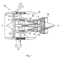
- a ducted fan gas turbine engine generally indicated at 10 has a principal and rotational axis X-X.
- the engine 10 comprises, in axial flow series, an air intake 11, a propulsive fan 12, an intermediate pressure compressor 13, a high-pressure compressor 14, combustion equipment 15, a high-pressure turbine 16, and intermediate pressure turbine 17, a low-pressure turbine 18 and a core engine exhaust nozzle 19.
- the engine also has a bypass duct 22 and a bypass exhaust nozzle 23.
- the gas turbine engine 10 shown in Figure 1 shows two electrical panels 200 which may be used to transmit/transfer electrical signals (or electricity, including electrical power and/or electrical control signals) around the engine and/or to/from the engine 10 from other components, such as components of an airframe.
- electrical signals or electricity, including electrical power and/or electrical control signals
- Each electrical panel 200 comprises at least one electrical conductor 252 embedded in a rigid composite material 220.
- the electrical conductors 252 in the electrical panel 200 may be provided in a harness, which may be a flexible circuit.
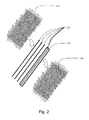
- Figure 2 shows components of an example of an electrical panel 200 prior to moulding.
- the electrical conductors 252 are provided between two layers of material 230, 240 that, after construction, form the rigid material 220. Some of the electrical conductors 252 are provided in a flexible circuit 250. Others may be single tracks, each surrounded by an electrically insulating sleeve.
- the material 230, 240 may be a fibre and resin compound. Such a fibre and resin compound may, after suitable treatment (for example heat treatment), produce the rigid composite material 220.
- the fibre and resin compound is formed of a sheet of interwoven fibres, or strands.
- the strands in Figure 2 extend in perpendicular directions, although the strands may extend in any one or more directions as required.
- the strands/fibres may be pre-impregnated (or "pre-pregged") with the resin.
- the desired shape may be, for example, a shape that corresponds to (for example is offset from) a part of a gas turbine engine, such as, by way of example only, at least a part of a casing, such as an engine fan casing or engine core casing. This may enable the final panel to adopt shapes that are curved in two-dimensions or three-dimensions.
- any suitable moulding method could be used to produce the electrical panel 200.
- the strands/fibres need not be pre-impregnated with the resin.
- the fibres/strands could be put into position (for example relative to electrical conductors 252/flexible circuit 250) in a dry state, and then the resin could be fed (or pumped) into the mould.
- Such a process may be referred to as a resin transfer method.
- no fibre may be used at all in the rigid material 220.
- Figure 3 shows schematically a transverse cross-section through a pattern 300 used to form a mould for moulding one of the panels 200.
- the pattern 300 is formed from a plurality of separate pattern segments 310 which are joined (e.g. bolted) together to form the complete pattern.
- a support structure (not shown) may be used to support the segments 310.
- the segments 310 are planar and combine to form a pattern 300 which has curved facetted shape. This is also the shape of the final panel 200 and allows it to wrap around the fan case of the engine.
- the flat segments are simple to produce, and the facets on the finished panel provide convenient mounting surfaces for other components.
- the segments 310 are all of a standard length and of a standard angular extent, which can help to speed up the production of the pattern.
- the pattern 300 is used to form a corresponding curved facetted mould 400 ( Figure 4 ). This can be done, for example, by laying up composite material against the pattern, curing the composite material, and then separating it from the pattern ( Figure 5 ).
- the mould can be used to manufacture the panel 200 by moulding polymer matrix composite material against mould 400 as described above.
Landscapes
- Engineering & Computer Science (AREA)
- Mechanical Engineering (AREA)
- Chemical & Material Sciences (AREA)
- General Engineering & Computer Science (AREA)
- Combustion & Propulsion (AREA)
- Materials Engineering (AREA)
- Structures Of Non-Positive Displacement Pumps (AREA)
Abstract
Description
- The present disclosure relates to a method of producing a tooling to be used for manufacturing a rigid panel formed of polymer matrix composite material, a method of manufacturing a rigid panel, an a rigid panel.
- A typical gas turbine engine has a substantial number of electrical components which serve, for example, to sense operating parameters of the engine and/or to control actuators which operate devices in the engine. Such devices may, for example, control fuel flow, variable vanes and air bleed valves. The actuators may themselves be electrically powered, although some may be pneumatically or hydraulically powered, but controlled by electrical signals.
- Electrical power, and signals to and from the individual electrical components, is commonly transmitted along conductors. Conventionally, such conductors may be in the form of wires and/or cables which are assembled together in a harness. In such a conventional harness, each wire may be surrounded by an insulating sleeve, which may be braided or have a braided cover.
- The harnesses are assembled from individual wires and cables which are held together over at least part of their lengths by suitable sleeving and/or braiding. Individual wires and cables emerge from the sleeving or braiding to terminate at plug or socket connector components for cooperation with complementary socket or plug connector components on, or connected to, the respective electrical components.
- Each conventional harness comprises a multitude of insulated wires and cables. This makes the conventional harness itself bulky, heavy and difficult to manipulate. The conventional harnesses occupy significant space within a gas turbine engine (for example within the nacelle of a gas turbine engine), and thus may compromise the design of the aircraft, for example the size and/or weight and/or shape of the nacelle.
- Conventional harnesses comprise a large number of components, including various individual wires and/or bundles of wires, supporting components (such as brackets or cables) and electrical and/or mechanical connectors. This can make the assembly process complicated (and thus susceptible to errors) and/or time consuming. Disassembly of the conventional harnesses (for example removal of the conventional harnesses from a gas turbine engine during maintenance) may also be complicated and/or time consuming. Thus, in many maintenance (or repair or overhaul) procedures on a gas turbine engine, removal and subsequent refitting of the conventional electrical harness may account for a very significant portion of the operation time and/or account for a significant proportion of the potential assembly errors.
- The electrical conductors in the conventional harnesses may be susceptible to mechanical damage. For example, mechanical damage may occur during installation (for example through accidental piercing of the protective sleeves/braiding) and/or during service (for example due to vibration). In order to reduce the likelihood of damage to the conductors in a conventional harness, the protective sleeves/braiding may need to be further reinforced, adding still further weight and reducing the ease with which they can be manipulated. Similarly, the exposed electrical connectors used to connect one conductor to another conductor or conductors to electrical units may be susceptible to damage and/or may add significant weight to the engine.
- Similar problems can be associated with fluid passages carrying e.g. hydraulic or pneumatic fluid.
- Accordingly, it has been proposed to replace conventional harnesses with rigid panels, typically formed of composite material, in which electrical conductors and/or fluid passages are embedded in the panel. See, for example,
US 2013/160458 (hereby incorporated by reference) for a description of such a panel or "raft". - Transferring electrical signals using an embedded electrical system of a rigid panel can provide a number of advantages over transferring electrical signals using a conventional harness. For example, during assembly and in use, such panels may provide greater protection to their electrical conductors than conventional harnesses. Further, the use of such panels may significantly reduce the build and maintenance times of an engine, and/or reduce the possibility of errors occurring during such procedures. The panels can also provide weight and size advantages over conventional harnesses. Similar advantages accrue when fluids are transferred using the embedded fluid system of the rigid panel.
- Such panels can conveniently be formed by moulding a polymer matrix composite material against a mould which is a "negative" of the final panel. The mould can be formed directly, e.g. from tooling board or aluminium alloy, or it can itself be formed by moulding a (typically composite) material against a pattern which is a "positive" of the final panel.
- The panels can be of large size (e.g. several metres in length) and typically have a curved shape which allows them to be wrapped around at least a part of a circumference of the engine (e.g. around a fan case). In addition, it is common to add additional detailed patterns/moulds to the larger pattern/mould in order to form smaller details of the panel.
- A problem arises, however, in that production of the tooling cannot be started until a final design for the panel is complete. This can delay the production of the tooling with a corresponding impact on the length of the entire the design-to-manufacture program for the finished panel. Subsequently, if modifications to the panel are required, then these can be costly and time-consuming to implement in the tooling.
- Accordingly, in a first aspect, the present invention provides a method of producing a tooling to be used for manufacturing a rigid panel formed of polymer matrix composite material, the panel being for attachment to a gas turbine engine and having a curved shape which allows the panel to be wrapped around at least a part of a circumference of the engine, and the panel having plural electrical conductors and/or fluid passages embedded therein, the tooling being either a mould against which the polymer matrix composite material can be moulded to manufacture the panel, or a pattern from which such a mould can be formed, the method including:
- providing a plurality of separate tooling segments, each of which corresponds to a respective region of the curved shape of the panel; and
- joining the tooling segments together to produce the tooling.
- Where reference is made herein to a curved shape (for example in the context of the panel being a curved shape), it will be understood that this includes generally curved and/or curved on a macroscopic level, and therefore includes shapes which comprise a series of flat facets that combine to form a generally curved overall shape.
- By forming the tooling from separate tooling segments, each segment can be produced individually as and when the detailed design for that segment is completed, thereby speeding up the production of the tooling. Further, if a modification to the panel is required, it may be necessary to alter only one or a few of the segments, which can reduce the time to implement the modification. In particular, relatively small segments can be re-machined on a small machine tool, whereas re-machining of a complete tooling can require a much larger machine tool.
- The panel may have a plurality of flat facets which combine to form the curved shape. In this case, each tooling segment can correspond to a respective one of the facets. It can be difficult and expensive to locate features onto a curved surface, for example as flats may have to be specially machined. However, by forming panel as a facetted curved shape such problems can be avoided. Further, by forming each tooling segment a respective one of the facets, the production of the individual segments can be simplified, as it is generally easier to produce a flat shape than a curved shape.
- The tooling segments can be joined together in the tooling by known joining techniques, such as location pins and bolts.
- The method may further include providing a support structure to support the joined tooling segments in the tooling.
- The segments may all be of a standard length (in the axial direction of the engine, for example), and of a standard angular extent (around the circumference of the engine). Standardisation of the segments in this way can further speed up the production of the tooling.
- A further aspect of the present invention provides a process for manufacturing a rigid panel formed of polymer matrix composite material, the panel being for attachment to a gas turbine engine and having a curved shape which allows the panel to be wrapped around at least a part of a circumference of the engine, and the panel having plural electrical conductors and/or fluid passages embedded therein, the process including:
- performing the method of the first aspect, the tooling being a mould; and
- moulding polymer matrix composite material against the mould to manufacture the panel.
- And a related further aspect of the present invention provides a process for manufacturing a rigid panel formed of polymer matrix composite material, the panel being for attachment to a gas turbine engine and having a curved shape which allows the panel to be wrapped around at least a part of a circumference of the engine, and the panel having plural electrical conductors and/or fluid passages embedded therein, the process including:
- performing the method of the first aspect, the tooling being a pattern;
- using the pattern to form a mould; and
- moulding polymer matrix composite material against the mould to manufacture the panel.
- The process of either of these further aspects may further include attaching the panel to a gas turbine engine such that the panel wraps around at least a part of a circumference of the engine.
- In another aspect, the present invention provides a rigid panel formed of polymer matrix composite material, the panel being for attachment to a gas turbine engine and having a curved shape (e.g. a facetted curved shape) which allows the panel to be wrapped around at least a part of a circumference of the engine, and the panel having plural electrical conductors and/or fluid passages embedded therein, wherein the panel is manufactured according to the process of the previous aspects.
- According to an aspect, there is provided a rigid panel formed of polymer matrix composite material, the panel being for attachment to a gas turbine engine and comprising plural electrical conductors and/or fluid passages embedded therein, wherein: the rigid panel comprises a plurality of flat facets which combine to form a curved shape which allows the panel to be wrapped around at least part of a circumference of the engine.
- In another aspect, the present invention provides a gas turbine engine to which is attached the panel of the previous aspect.
- Further optional features of the invention will now be set out. These are applicable singly or in any combination with any aspect of the invention.
- The panels may be referred to as rafts, rigid rafts, electrical rafts, or rigid electrical rafts.
- The composite material may have a particulate or fibre reinforced polymer matrix, such as a continuous fibre reinforced polymer matrix. The composite material may comprise any suitable combination of resin and fibre as desired for a particular application. Any suitable fibres may be used, for example carbon fibres, glass fibres, aramid fibres, and/or para-aramid fibres. The fibres may be of any type, such as woven and/or chopped. Any suitable resin may be used, for example epoxy, BMI (bismaleimide), PEEK (polyetheretherketone), PTFE (polytetraflouroethylene), PAEK (polyaryletherketone), polyurethane, and/or polyamides (such as nylon).
- The panel may have one or more electrical conductors embedded therein. Such electrical conductors may be in the form of, for example, one or more flexible printed circuits, one or more wires (which may be sheathed), or a combination thereof.
- The panel may comprise one or more electrical connectors or sockets, which may be electrically connected to the electrical conductors, e.g. by mechanical crimping. The electrical connector or socket may allow electrical connection of the panel to other electrical components, for example to other such structures (either directly or indirectly, via an electrical cable or lead) or to electrical units (again, either directly or indirectly, via an electrical cable or lead). Such an electrical connector or socket may take any suitable form, and may be at least partially embedded in the structure.
- The panel may have one or more fluid passages embedded therein. The fluid passages may be part of a fluid system, such as a gas system (for example carrying pneumatic or cooling gas/air), and/or a liquid system (for example carrying a fuel, hydraulic and/or lubricant liquid).
- The panel may be provided in any suitable location/position of the gas turbine engine, for example to a mounting structure at any suitable location. For example, the panel may be attached to the engine core case or engine fan case, for example to a mounting structure on such cases.
- Other components/systems of a gas turbine engine may be provided to the panel in any suitable manner. Thus, a surface of the panel may be used as a mounting surface for other gas turbine engine components/systems.
- For example, one or more electrical units may be mounted on the panel. The electrical unit(s) may be any type of electronic control unit (ECU), such as an Electronic Engine Controller (EEC) and an Engine Health Monitoring Unit (EMU). The panel may be a particularly convenient, lightweight and/or compact way of providing (for example attaching, fixing or mounting) an electrical unit to a turbine engine. For example, the electrical unit and the panel may be assembled together (mechanically and/or electrically) before being installed on the gas turbine engine.
- The panel may be provided with at least one mount on which other components (e.g. auxiliary/ancillary components/systems) of the gas turbine engine may be mounted. The mount may be a bracket, for example a bespoke bracket for the component/system mounted thereon or a conventional/standard bracket. Fluid pipes for transferring fluid around the engine may be mounted to the panel (e.g. mechanically mounted using a bracket), and thus to the engine.
- One or more anti-vibration mounts may be used to attach the panel to another component, thereby allowing the panel to be vibration isolated (or at least substantially vibration isolated). Using an anti-vibration mount to attach the panel to a gas turbine engine may reduce (or substantially eliminate) the amount of vibration being passed to the panel from the gas turbine engine, for example during use. This may help to prolong the life of the panel. Furthermore, any other components that may be attached to the panel may also benefit from being mounted to the gas turbine engine via the anti-vibration mounts, through being mounted on the panel.
- Embodiments of the invention will now be described by way of example with reference to the accompanying drawings in which:
-
Figure 1 shows a longitudinal cross-section through a ducted fan gas turbine engine; -
Figure 2 shows components of an example of an electrical panel prior to moulding; -
Figure 3 shows schematically a transverse cross-section through a pattern used to form a mould for moulding one of the panels of the engine ofFigure 1 ; -
Figure 4 shows the pattern ofFigure 3 used to form a mould; and -
Figure 5 shows the mould ofFigure 4 separated from the pattern. - With reference to
Figure 1 , a ducted fan gas turbine engine generally indicated at 10 has a principal and rotational axis X-X. Theengine 10 comprises, in axial flow series, an air intake 11, apropulsive fan 12, anintermediate pressure compressor 13, a high-pressure compressor 14,combustion equipment 15, a high-pressure turbine 16, andintermediate pressure turbine 17, a low-pressure turbine 18 and a coreengine exhaust nozzle 19. The engine also has abypass duct 22 and abypass exhaust nozzle 23. - The
gas turbine engine 10 works in a conventional manner so that air entering the intake 11 is accelerated by thefan 12 to produce two air flows: a first air flow A into theintermediate pressure compressor 13 and a second air flow B which passes through thebypass duct 22 to provide propulsive thrust. Theintermediate pressure compressor 13 compresses the air flow A directed into it before delivering that air to thehigh pressure compressor 14 where further compression takes place. - The compressed air exhausted from the high-
pressure compressor 14 is directed into thecombustion equipment 15 where it is mixed with fuel and the mixture combusted. The resultant hot combustion products then expand through, and thereby drive the high, intermediate and low-pressure turbines nozzle 19 to provide additional propulsive thrust. The high, intermediate and low-pressure turbines intermediate pressure compressors fan 12 by suitable interconnecting shafts. - The
gas turbine engine 10 shown inFigure 1 shows twoelectrical panels 200 which may be used to transmit/transfer electrical signals (or electricity, including electrical power and/or electrical control signals) around the engine and/or to/from theengine 10 from other components, such as components of an airframe. - Each
electrical panel 200 comprises at least oneelectrical conductor 252 embedded in a rigidcomposite material 220. Theelectrical conductors 252 in theelectrical panel 200 may be provided in a harness, which may be a flexible circuit. - Each
electrical panel 200 is manufactured by a moulding method. For example, therigid material 220 may initially be provided as layers of flexible material, such as (by way of example only) layers of fibre and resin compound. This flexible material may be placed against a mould having a desired shape. Other components (such as fluid pipes and/or theelectrical conductors 252, which may be embedded in a flexible circuit) may also be placed into the mould, for example between layers of the flexible material from which therigid material 220 is ultimately formed. -
Figure 2 shows components of an example of anelectrical panel 200 prior to moulding. Theelectrical conductors 252 are provided between two layers ofmaterial rigid material 220. Some of theelectrical conductors 252 are provided in aflexible circuit 250. Others may be single tracks, each surrounded by an electrically insulating sleeve. Thematerial composite material 220. In the example ofFigure 2 , the fibre and resin compound is formed of a sheet of interwoven fibres, or strands. The strands inFigure 2 extend in perpendicular directions, although the strands may extend in any one or more directions as required. The strands/fibres may be pre-impregnated (or "pre-pregged") with the resin. - Prior to any treatment, both the first and
second layers electrical conductors 252 may be flexible, for example supple, pliable or malleable. As such, when thelayers electrical conductors 252 are placed together, they may be moulded, or formed, into any desired shape. For example, thelayers electrical conductors 252 may be placed against the mould (which may be of any suitable form, such as a glass or an aluminium mould) having the desired shape. The desired shape may be, for example, a shape that corresponds to (for example is offset from) a part of a gas turbine engine, such as, by way of example only, at least a part of a casing, such as an engine fan casing or engine core casing. This may enable the final panel to adopt shapes that are curved in two-dimensions or three-dimensions. - Any suitable moulding method could be used to produce the
electrical panel 200. For example, the strands/fibres need not be pre-impregnated with the resin. Instead, the fibres/strands could be put into position (for example relative toelectrical conductors 252/flexible circuit 250) in a dry state, and then the resin could be fed (or pumped) into the mould. Such a process may be referred to as a resin transfer method. In some constructions no fibre may be used at all in therigid material 220. -
Figure 3 shows schematically a transverse cross-section through apattern 300 used to form a mould for moulding one of thepanels 200. Thepattern 300 is formed from a plurality ofseparate pattern segments 310 which are joined (e.g. bolted) together to form the complete pattern. A support structure (not shown) may be used to support thesegments 310. - The
segments 310 are planar and combine to form apattern 300 which has curved facetted shape. This is also the shape of thefinal panel 200 and allows it to wrap around the fan case of the engine. The flat segments are simple to produce, and the facets on the finished panel provide convenient mounting surfaces for other components. - Preferably, the
segments 310 are all of a standard length and of a standard angular extent, which can help to speed up the production of the pattern. However, this need not be the case, and some arrangements may have segments with different lengths and/or angular extents to other segments. - Some of the
segments 310 have detail features 320, such as brackets of connectors, or return features 330. Advantageously, by forming thepattern 300 from a plurality ofsuch segments 310, each segment can be produced as that design detail of that part of panel is finalised. - Having produced the
pattern 300, it is used to form a corresponding curved facetted mould 400 (Figure 4 ). This can be done, for example, by laying up composite material against the pattern, curing the composite material, and then separating it from the pattern (Figure 5 ). The mould can be used to manufacture thepanel 200 by moulding polymer matrix composite material againstmould 400 as described above. - Instead of producing a pattern from segments and then forming the mould, another option is to provide mould segments (e.g. formed from tooling board or aluminium) which are joined together to produce the mould. This approach has similar advantages of reduced lead times for new designs and subsequent modifications, and (in the case of a facetted curved panel) improved subsequent processing due to flat facet surfaces.
- While the invention has been described in conjunction with the exemplary embodiments described above, many equivalent modifications and variations will be apparent to those skilled in the art when given this disclosure. Accordingly, the exemplary embodiments of the invention set forth above are considered to be illustrative and not limiting. Various changes to the described embodiments may be made without departing from the spirit and scope of the invention.
Claims (6)
- A method of producing a tooling to be used for manufacturing a rigid panel (200) formed of polymer matrix composite material (220), the panel being for attachment to a gas turbine engine (10) and having a curved shape which allows the panel to be wrapped around at least a part of a circumference of the engine, and the panel having a plurality of flat facets which combine to form the curved shape and plural electrical conductors (252) and/or fluid passages embedded therein, the tooling being either a mould against which the polymer matrix composite material can be moulded to manufacture the panel, or a pattern (300) from which such a mould can be formed, the method including:providing a plurality of separate tooling segments (310), each of which corresponds to a respective flat facet of the panel; andjoining the tooling segments together to produce the tooling.
- A method according to claim 1, wherein the segments are all of a standard length and of a standard angular extent.
- A process for manufacturing a rigid panel (200) formed of polymer matrix composite material (220), the panel being for attachment to a gas turbine engine (10) and having a plurality of flat facets which combine to form a curved shape which allows the panel to be wrapped around at least a part of a circumference of the engine, and the panel having plural electrical conductors and/or fluid passages embedded therein, the process including:performing the method of claim 1 or claim 2, the tooling being a mould; andmoulding polymer matrix composite material against the mould to manufacture the panel.
- A process for manufacturing a rigid panel (200) formed of polymer matrix composite material (220), the panel being for attachment to a gas turbine engine (10) and having a plurality of flat facets which combine to form a curved shape which allows the panel to be wrapped around at least a part of a circumference of the engine, and the panel having plural electrical conductors and/or fluid passages embedded therein, the process including:performing the method of claim 1 or claim 2, the tooling being a pattern (300);using the pattern to form a mould; andmoulding polymer matrix composite material against the mould to manufacture the panel.
- A process according to claim 3 or claim 4, further including attaching the panel (200) to a gas turbine engine (10) such that the panel wraps around at least a part of a circumference of the engine.
- A rigid panel formed of polymer matrix composite material (220), the panel being for attachment to a gas turbine engine (10) and comprising plural electrical conductors and/or fluid passages embedded therein, wherein:the rigid panel comprises a plurality of flat facets which combine to form a curved shape which allows the panel to be wrapped around at least part of a circumference of the engine.
Applications Claiming Priority (1)
| Application Number | Priority Date | Filing Date | Title |
|---|---|---|---|
| GBGB1417695.2A GB201417695D0 (en) | 2014-10-07 | 2014-10-07 | Tooling production method |
Publications (2)
| Publication Number | Publication Date |
|---|---|
| EP3006179A1 true EP3006179A1 (en) | 2016-04-13 |
| EP3006179B1 EP3006179B1 (en) | 2017-11-08 |
Family
ID=51946958
Family Applications (1)
| Application Number | Title | Priority Date | Filing Date |
|---|---|---|---|
| EP15187558.0A Active EP3006179B1 (en) | 2014-10-07 | 2015-09-30 | Rigid panel production method and so obtained panel |
Country Status (3)
| Country | Link |
|---|---|
| US (1) | US10156156B2 (en) |
| EP (1) | EP3006179B1 (en) |
| GB (1) | GB201417695D0 (en) |
Families Citing this family (3)
| Publication number | Priority date | Publication date | Assignee | Title |
|---|---|---|---|---|
| GB2498006B (en) | 2011-12-22 | 2014-07-09 | Rolls Royce Plc | Gas turbine engine systems |
| GB2497807B (en) | 2011-12-22 | 2014-09-10 | Rolls Royce Plc | Electrical harness |
| GB201306674D0 (en) * | 2013-04-12 | 2013-05-29 | Rolls Royce Plc | Rigid Raft for a Gas Turbine Engine |
Citations (3)
| Publication number | Priority date | Publication date | Assignee | Title |
|---|---|---|---|---|
| US6627835B1 (en) * | 2000-02-02 | 2003-09-30 | Purdue Research Foundation | Three dimensional object fabrication techniques |
| EP2407292A1 (en) * | 2010-07-14 | 2012-01-18 | Siemens Aktiengesellschaft | Negative mold comprising predefined foam blocks for casting a component and method for producing the negative mold |
| US20130160458A1 (en) * | 2011-12-22 | 2013-06-27 | Rolls-Royce Plc | Electrical raft assembly |
Family Cites Families (5)
| Publication number | Priority date | Publication date | Assignee | Title |
|---|---|---|---|---|
| US6958105B2 (en) | 2002-08-08 | 2005-10-25 | Airbus Deutschland Gmbh | Automated fabrication of an integral fiber reinforced composite structural component using a positioning and assembly support |
| WO2005049298A1 (en) | 2003-11-24 | 2005-06-02 | Qmi Solutions Limited | Forming and moulding tools and method of manufacture thereof |
| CA2667006A1 (en) | 2006-10-23 | 2008-05-02 | Constructions Industrielles De La Mediterranee - Cnim | Composite tool for moulding cylindrical parts |
| FR2953754B1 (en) | 2009-12-16 | 2018-03-02 | Airbus Operations | TOOLING FOR MANUFACTURING A PANEL OF COMPOSITE MATERIAL, PARTICULARLY AN AIRCRAFT FUSELAGE |
| DK177679B1 (en) | 2012-10-03 | 2014-02-24 | Dencam Composite As | Segmented Plug Device |
-
2014
- 2014-10-07 GB GBGB1417695.2A patent/GB201417695D0/en not_active Ceased
-
2015
- 2015-09-30 EP EP15187558.0A patent/EP3006179B1/en active Active
- 2015-09-30 US US14/871,046 patent/US10156156B2/en active Active
Patent Citations (3)
| Publication number | Priority date | Publication date | Assignee | Title |
|---|---|---|---|---|
| US6627835B1 (en) * | 2000-02-02 | 2003-09-30 | Purdue Research Foundation | Three dimensional object fabrication techniques |
| EP2407292A1 (en) * | 2010-07-14 | 2012-01-18 | Siemens Aktiengesellschaft | Negative mold comprising predefined foam blocks for casting a component and method for producing the negative mold |
| US20130160458A1 (en) * | 2011-12-22 | 2013-06-27 | Rolls-Royce Plc | Electrical raft assembly |
Also Published As
| Publication number | Publication date |
|---|---|
| EP3006179B1 (en) | 2017-11-08 |
| US10156156B2 (en) | 2018-12-18 |
| US20160096288A1 (en) | 2016-04-07 |
| GB201417695D0 (en) | 2014-11-19 |
Similar Documents
| Publication | Publication Date | Title |
|---|---|---|
| EP2607665B1 (en) | Gas Turbine Engine Part | |
| US9253870B2 (en) | Fire resistant electrical panel | |
| EP2607660B1 (en) | Electrical harness | |
| US9478896B2 (en) | Electrical connectors | |
| EP2789830B1 (en) | Mounting arrangement | |
| US9259808B2 (en) | Method of servicing a gas turbine engine | |
| EP2800208B1 (en) | Electrical connectors | |
| EP2759721A2 (en) | Component having insert for receiving threaded fasteners | |
| EP2799477B1 (en) | Composite structure | |
| EP2799476A1 (en) | Composite structure | |
| EP2802193B1 (en) | Gas turbine engine | |
| EP2789831B1 (en) | Rigid raft for a gas turbine engine | |
| EP2800210A2 (en) | Electrical unit with electrical connector | |
| EP3006179B1 (en) | Rigid panel production method and so obtained panel | |
| EP2685565A1 (en) | Electrical connectors | |
| EP3437844A1 (en) | Method for producing a rigid plate | |
| HK1181097B (en) | Electrical harness |
Legal Events
| Date | Code | Title | Description |
|---|---|---|---|
| PUAI | Public reference made under article 153(3) epc to a published international application that has entered the european phase |
Free format text: ORIGINAL CODE: 0009012 |
|
| AK | Designated contracting states |
Kind code of ref document: A1 Designated state(s): AL AT BE BG CH CY CZ DE DK EE ES FI FR GB GR HR HU IE IS IT LI LT LU LV MC MK MT NL NO PL PT RO RS SE SI SK SM TR |
|
| AX | Request for extension of the european patent |
Extension state: BA ME |
|
| 17P | Request for examination filed |
Effective date: 20160915 |
|
| RBV | Designated contracting states (corrected) |
Designated state(s): AL AT BE BG CH CY CZ DE DK EE ES FI FR GB GR HR HU IE IS IT LI LT LU LV MC MK MT NL NO PL PT RO RS SE SI SK SM TR |
|
| GRAP | Despatch of communication of intention to grant a patent |
Free format text: ORIGINAL CODE: EPIDOSNIGR1 |
|
| STAA | Information on the status of an ep patent application or granted ep patent |
Free format text: STATUS: GRANT OF PATENT IS INTENDED |
|
| GRAS | Grant fee paid |
Free format text: ORIGINAL CODE: EPIDOSNIGR3 |
|
| GRAA | (expected) grant |
Free format text: ORIGINAL CODE: 0009210 |
|
| STAA | Information on the status of an ep patent application or granted ep patent |
Free format text: STATUS: THE PATENT HAS BEEN GRANTED |
|
| INTG | Intention to grant announced |
Effective date: 20170920 |
|
| AK | Designated contracting states |
Kind code of ref document: B1 Designated state(s): AL AT BE BG CH CY CZ DE DK EE ES FI FR GB GR HR HU IE IS IT LI LT LU LV MC MK MT NL NO PL PT RO RS SE SI SK SM TR |
|
| REG | Reference to a national code |
Ref country code: GB Ref legal event code: FG4D |
|
| REG | Reference to a national code |
Ref country code: CH Ref legal event code: EP Ref country code: AT Ref legal event code: REF Ref document number: 943714 Country of ref document: AT Kind code of ref document: T Effective date: 20171115 |
|
| REG | Reference to a national code |
Ref country code: IE Ref legal event code: FG4D |
|
| REG | Reference to a national code |
Ref country code: DE Ref legal event code: R096 Ref document number: 602015005859 Country of ref document: DE |
|
| REG | Reference to a national code |
Ref country code: NL Ref legal event code: MP Effective date: 20171108 |
|
| REG | Reference to a national code |
Ref country code: LT Ref legal event code: MG4D |
|
| REG | Reference to a national code |
Ref country code: AT Ref legal event code: MK05 Ref document number: 943714 Country of ref document: AT Kind code of ref document: T Effective date: 20171108 |
|
| PG25 | Lapsed in a contracting state [announced via postgrant information from national office to epo] |
Ref country code: NO Free format text: LAPSE BECAUSE OF FAILURE TO SUBMIT A TRANSLATION OF THE DESCRIPTION OR TO PAY THE FEE WITHIN THE PRESCRIBED TIME-LIMIT Effective date: 20180208 Ref country code: SE Free format text: LAPSE BECAUSE OF FAILURE TO SUBMIT A TRANSLATION OF THE DESCRIPTION OR TO PAY THE FEE WITHIN THE PRESCRIBED TIME-LIMIT Effective date: 20171108 Ref country code: FI Free format text: LAPSE BECAUSE OF FAILURE TO SUBMIT A TRANSLATION OF THE DESCRIPTION OR TO PAY THE FEE WITHIN THE PRESCRIBED TIME-LIMIT Effective date: 20171108 Ref country code: LT Free format text: LAPSE BECAUSE OF FAILURE TO SUBMIT A TRANSLATION OF THE DESCRIPTION OR TO PAY THE FEE WITHIN THE PRESCRIBED TIME-LIMIT Effective date: 20171108 Ref country code: ES Free format text: LAPSE BECAUSE OF FAILURE TO SUBMIT A TRANSLATION OF THE DESCRIPTION OR TO PAY THE FEE WITHIN THE PRESCRIBED TIME-LIMIT Effective date: 20171108 Ref country code: NL Free format text: LAPSE BECAUSE OF FAILURE TO SUBMIT A TRANSLATION OF THE DESCRIPTION OR TO PAY THE FEE WITHIN THE PRESCRIBED TIME-LIMIT Effective date: 20171108 |
|
| PG25 | Lapsed in a contracting state [announced via postgrant information from national office to epo] |
Ref country code: RS Free format text: LAPSE BECAUSE OF FAILURE TO SUBMIT A TRANSLATION OF THE DESCRIPTION OR TO PAY THE FEE WITHIN THE PRESCRIBED TIME-LIMIT Effective date: 20171108 Ref country code: LV Free format text: LAPSE BECAUSE OF FAILURE TO SUBMIT A TRANSLATION OF THE DESCRIPTION OR TO PAY THE FEE WITHIN THE PRESCRIBED TIME-LIMIT Effective date: 20171108 Ref country code: IS Free format text: LAPSE BECAUSE OF FAILURE TO SUBMIT A TRANSLATION OF THE DESCRIPTION OR TO PAY THE FEE WITHIN THE PRESCRIBED TIME-LIMIT Effective date: 20180308 Ref country code: GR Free format text: LAPSE BECAUSE OF FAILURE TO SUBMIT A TRANSLATION OF THE DESCRIPTION OR TO PAY THE FEE WITHIN THE PRESCRIBED TIME-LIMIT Effective date: 20180209 Ref country code: HR Free format text: LAPSE BECAUSE OF FAILURE TO SUBMIT A TRANSLATION OF THE DESCRIPTION OR TO PAY THE FEE WITHIN THE PRESCRIBED TIME-LIMIT Effective date: 20171108 Ref country code: AT Free format text: LAPSE BECAUSE OF FAILURE TO SUBMIT A TRANSLATION OF THE DESCRIPTION OR TO PAY THE FEE WITHIN THE PRESCRIBED TIME-LIMIT Effective date: 20171108 Ref country code: BG Free format text: LAPSE BECAUSE OF FAILURE TO SUBMIT A TRANSLATION OF THE DESCRIPTION OR TO PAY THE FEE WITHIN THE PRESCRIBED TIME-LIMIT Effective date: 20180208 |
|
| PG25 | Lapsed in a contracting state [announced via postgrant information from national office to epo] |
Ref country code: CZ Free format text: LAPSE BECAUSE OF FAILURE TO SUBMIT A TRANSLATION OF THE DESCRIPTION OR TO PAY THE FEE WITHIN THE PRESCRIBED TIME-LIMIT Effective date: 20171108 Ref country code: EE Free format text: LAPSE BECAUSE OF FAILURE TO SUBMIT A TRANSLATION OF THE DESCRIPTION OR TO PAY THE FEE WITHIN THE PRESCRIBED TIME-LIMIT Effective date: 20171108 Ref country code: CY Free format text: LAPSE BECAUSE OF FAILURE TO SUBMIT A TRANSLATION OF THE DESCRIPTION OR TO PAY THE FEE WITHIN THE PRESCRIBED TIME-LIMIT Effective date: 20171108 Ref country code: SK Free format text: LAPSE BECAUSE OF FAILURE TO SUBMIT A TRANSLATION OF THE DESCRIPTION OR TO PAY THE FEE WITHIN THE PRESCRIBED TIME-LIMIT Effective date: 20171108 Ref country code: DK Free format text: LAPSE BECAUSE OF FAILURE TO SUBMIT A TRANSLATION OF THE DESCRIPTION OR TO PAY THE FEE WITHIN THE PRESCRIBED TIME-LIMIT Effective date: 20171108 |
|
| REG | Reference to a national code |
Ref country code: DE Ref legal event code: R097 Ref document number: 602015005859 Country of ref document: DE |
|
| PG25 | Lapsed in a contracting state [announced via postgrant information from national office to epo] |
Ref country code: IT Free format text: LAPSE BECAUSE OF FAILURE TO SUBMIT A TRANSLATION OF THE DESCRIPTION OR TO PAY THE FEE WITHIN THE PRESCRIBED TIME-LIMIT Effective date: 20171108 Ref country code: RO Free format text: LAPSE BECAUSE OF FAILURE TO SUBMIT A TRANSLATION OF THE DESCRIPTION OR TO PAY THE FEE WITHIN THE PRESCRIBED TIME-LIMIT Effective date: 20171108 Ref country code: PL Free format text: LAPSE BECAUSE OF FAILURE TO SUBMIT A TRANSLATION OF THE DESCRIPTION OR TO PAY THE FEE WITHIN THE PRESCRIBED TIME-LIMIT Effective date: 20171108 Ref country code: SM Free format text: LAPSE BECAUSE OF FAILURE TO SUBMIT A TRANSLATION OF THE DESCRIPTION OR TO PAY THE FEE WITHIN THE PRESCRIBED TIME-LIMIT Effective date: 20171108 |
|
| PLBE | No opposition filed within time limit |
Free format text: ORIGINAL CODE: 0009261 |
|
| STAA | Information on the status of an ep patent application or granted ep patent |
Free format text: STATUS: NO OPPOSITION FILED WITHIN TIME LIMIT |
|
| REG | Reference to a national code |
Ref country code: FR Ref legal event code: PLFP Year of fee payment: 4 |
|
| 26N | No opposition filed |
Effective date: 20180809 |
|
| PG25 | Lapsed in a contracting state [announced via postgrant information from national office to epo] |
Ref country code: SI Free format text: LAPSE BECAUSE OF FAILURE TO SUBMIT A TRANSLATION OF THE DESCRIPTION OR TO PAY THE FEE WITHIN THE PRESCRIBED TIME-LIMIT Effective date: 20171108 |
|
| PG25 | Lapsed in a contracting state [announced via postgrant information from national office to epo] |
Ref country code: MC Free format text: LAPSE BECAUSE OF FAILURE TO SUBMIT A TRANSLATION OF THE DESCRIPTION OR TO PAY THE FEE WITHIN THE PRESCRIBED TIME-LIMIT Effective date: 20171108 |
|
| REG | Reference to a national code |
Ref country code: CH Ref legal event code: PL |
|
| REG | Reference to a national code |
Ref country code: BE Ref legal event code: MM Effective date: 20180930 |
|
| REG | Reference to a national code |
Ref country code: IE Ref legal event code: MM4A |
|
| PG25 | Lapsed in a contracting state [announced via postgrant information from national office to epo] |
Ref country code: LU Free format text: LAPSE BECAUSE OF NON-PAYMENT OF DUE FEES Effective date: 20180930 |
|
| PG25 | Lapsed in a contracting state [announced via postgrant information from national office to epo] |
Ref country code: IE Free format text: LAPSE BECAUSE OF NON-PAYMENT OF DUE FEES Effective date: 20180930 |
|
| PG25 | Lapsed in a contracting state [announced via postgrant information from national office to epo] |
Ref country code: BE Free format text: LAPSE BECAUSE OF NON-PAYMENT OF DUE FEES Effective date: 20180930 Ref country code: CH Free format text: LAPSE BECAUSE OF NON-PAYMENT OF DUE FEES Effective date: 20180930 Ref country code: LI Free format text: LAPSE BECAUSE OF NON-PAYMENT OF DUE FEES Effective date: 20180930 |
|
| PG25 | Lapsed in a contracting state [announced via postgrant information from national office to epo] |
Ref country code: MT Free format text: LAPSE BECAUSE OF NON-PAYMENT OF DUE FEES Effective date: 20180930 |
|
| PG25 | Lapsed in a contracting state [announced via postgrant information from national office to epo] |
Ref country code: TR Free format text: LAPSE BECAUSE OF FAILURE TO SUBMIT A TRANSLATION OF THE DESCRIPTION OR TO PAY THE FEE WITHIN THE PRESCRIBED TIME-LIMIT Effective date: 20171108 |
|
| PG25 | Lapsed in a contracting state [announced via postgrant information from national office to epo] |
Ref country code: PT Free format text: LAPSE BECAUSE OF FAILURE TO SUBMIT A TRANSLATION OF THE DESCRIPTION OR TO PAY THE FEE WITHIN THE PRESCRIBED TIME-LIMIT Effective date: 20171108 |
|
| PG25 | Lapsed in a contracting state [announced via postgrant information from national office to epo] |
Ref country code: HU Free format text: LAPSE BECAUSE OF FAILURE TO SUBMIT A TRANSLATION OF THE DESCRIPTION OR TO PAY THE FEE WITHIN THE PRESCRIBED TIME-LIMIT; INVALID AB INITIO Effective date: 20150930 Ref country code: MK Free format text: LAPSE BECAUSE OF NON-PAYMENT OF DUE FEES Effective date: 20171108 |
|
| PG25 | Lapsed in a contracting state [announced via postgrant information from national office to epo] |
Ref country code: AL Free format text: LAPSE BECAUSE OF FAILURE TO SUBMIT A TRANSLATION OF THE DESCRIPTION OR TO PAY THE FEE WITHIN THE PRESCRIBED TIME-LIMIT Effective date: 20171108 |
|
| P01 | Opt-out of the competence of the unified patent court (upc) registered |
Effective date: 20230528 |
|
| PGFP | Annual fee paid to national office [announced via postgrant information from national office to epo] |
Ref country code: DE Payment date: 20250926 Year of fee payment: 11 |
|
| PGFP | Annual fee paid to national office [announced via postgrant information from national office to epo] |
Ref country code: GB Payment date: 20250923 Year of fee payment: 11 |
|
| PGFP | Annual fee paid to national office [announced via postgrant information from national office to epo] |
Ref country code: FR Payment date: 20250925 Year of fee payment: 11 |