EP3006144A1 - Battery-type drilling machine - Google Patents
Battery-type drilling machine Download PDFInfo
- Publication number
- EP3006144A1 EP3006144A1 EP14803350.9A EP14803350A EP3006144A1 EP 3006144 A1 EP3006144 A1 EP 3006144A1 EP 14803350 A EP14803350 A EP 14803350A EP 3006144 A1 EP3006144 A1 EP 3006144A1
- Authority
- EP
- European Patent Office
- Prior art keywords
- battery
- drilling machine
- locking member
- drilling
- motor
- Prior art date
- Legal status (The legal status is an assumption and is not a legal conclusion. Google has not performed a legal analysis and makes no representation as to the accuracy of the status listed.)
- Granted
Links
Images






Classifications
-
- B—PERFORMING OPERATIONS; TRANSPORTING
- B23—MACHINE TOOLS; METAL-WORKING NOT OTHERWISE PROVIDED FOR
- B23B—TURNING; BORING
- B23B45/00—Hand-held or like portable drilling machines, e.g. drill guns; Equipment therefor
- B23B45/02—Hand-held or like portable drilling machines, e.g. drill guns; Equipment therefor driven by electric power
-
- H—ELECTRICITY
- H01—ELECTRIC ELEMENTS
- H01M—PROCESSES OR MEANS, e.g. BATTERIES, FOR THE DIRECT CONVERSION OF CHEMICAL ENERGY INTO ELECTRICAL ENERGY
- H01M50/00—Constructional details or processes of manufacture of the non-active parts of electrochemical cells other than fuel cells, e.g. hybrid cells
- H01M50/20—Mountings; Secondary casings or frames; Racks, modules or packs; Suspension devices; Shock absorbers; Transport or carrying devices; Holders
- H01M50/262—Mountings; Secondary casings or frames; Racks, modules or packs; Suspension devices; Shock absorbers; Transport or carrying devices; Holders with fastening means, e.g. locks
-
- H—ELECTRICITY
- H01—ELECTRIC ELEMENTS
- H01M—PROCESSES OR MEANS, e.g. BATTERIES, FOR THE DIRECT CONVERSION OF CHEMICAL ENERGY INTO ELECTRICAL ENERGY
- H01M50/00—Constructional details or processes of manufacture of the non-active parts of electrochemical cells other than fuel cells, e.g. hybrid cells
- H01M50/20—Mountings; Secondary casings or frames; Racks, modules or packs; Suspension devices; Shock absorbers; Transport or carrying devices; Holders
- H01M50/247—Mountings; Secondary casings or frames; Racks, modules or packs; Suspension devices; Shock absorbers; Transport or carrying devices; Holders specially adapted for portable devices, e.g. mobile phones, computers, hand tools or pacemakers
-
- B—PERFORMING OPERATIONS; TRANSPORTING
- B23—MACHINE TOOLS; METAL-WORKING NOT OTHERWISE PROVIDED FOR
- B23B—TURNING; BORING
- B23B2260/00—Details of constructional elements
- B23B2260/024—Batteries
-
- B—PERFORMING OPERATIONS; TRANSPORTING
- B23—MACHINE TOOLS; METAL-WORKING NOT OTHERWISE PROVIDED FOR
- B23B—TURNING; BORING
- B23B2260/00—Details of constructional elements
- B23B2260/122—Safety devices
-
- Y—GENERAL TAGGING OF NEW TECHNOLOGICAL DEVELOPMENTS; GENERAL TAGGING OF CROSS-SECTIONAL TECHNOLOGIES SPANNING OVER SEVERAL SECTIONS OF THE IPC; TECHNICAL SUBJECTS COVERED BY FORMER USPC CROSS-REFERENCE ART COLLECTIONS [XRACs] AND DIGESTS
- Y02—TECHNOLOGIES OR APPLICATIONS FOR MITIGATION OR ADAPTATION AGAINST CLIMATE CHANGE
- Y02E—REDUCTION OF GREENHOUSE GAS [GHG] EMISSIONS, RELATED TO ENERGY GENERATION, TRANSMISSION OR DISTRIBUTION
- Y02E60/00—Enabling technologies; Technologies with a potential or indirect contribution to GHG emissions mitigation
- Y02E60/10—Energy storage using batteries
Definitions
- the status indicator is indicating the warning sign, i.e. when the battery locking member is not in the advanced position, there is a possibility that the battery will be dislodged and the supply of electric power to the motor will be cut off. If the battery is dislodged and the motor is stopped suddenly during drilling, a problem may occur that the drilling tool stops drilling in the state of biting into the workpiece and becomes incapable of being removed from the workpiece, for example.
- the drilling machine body unit is securely held by the electromagnet as stated above, if removal of the battery occurs suddenly during drilling, the securely holding power of the electromagnet disappears. Consequently, the drilling machine may be swung by external force acting on the drilling tool performing drilling at that time, which may cause the drilling machine to fall down.
- the motor cannot be driven when there is a possibility of removal of the battery; therefore, it is possible to prevent drilling from taking place in a dangerous situation as stated above.
- the position detecting device may have a limit switch.
- the limit switch may be configured to be turned on/off when the battery locking member moves between the retracted position and the advanced position, thereby detecting a position of the battery locking member.
- the drilling tool 44 attached to the lower end of the drilling drive unit 14 is driven to rotate by the motor 48, and a feed handle 66 attached to the drilling machine body unit 12 is turned, thereby moving the drilling drive unit 14 downward relative to the drilling machine body unit 12 through a gear device comprising a rack 64 and a pinion 65, and thus drilling the workpiece with the drilling tool 44.
- the battery housing 22 comprises a right-side part 22-1 and a left-side part 22-2, which are defined by splitting the battery housing 22 at the center thereof.
- the right-side part 22-1 and the left-side part 22-2 are attached to the frame 20 in such a manner as to sandwich the frame 20 therebetween from the right and left sides.
- an interior space 24 ( Fig. 3 ) is formed between the battery housing 22 and the frame 20.
- a drive control circuit 36 is attached to the rear surface of the front wall portion 20-1 in parallel thereto at a position between right- and left-side ribs 20-3 and 20-4 ( Fig.4 ).
- the drive control circuit 36 controls electric power supplied from the battery 16 to the motor 48 of the drilling drive unit 14 and to an electromagnet 18-1 in the electromagnet-type securing unit 18.
- the electromagnet-type securing unit 18 attached to the lower side of the drilling machine body unit 12 is configured such that, when electric power from the battery 16 is supplied to the electromagnet 18-1 therein, the electromagnet-type securing unit 18 generates a magnetic field and thus magnetically adheres to a workpiece made of a magnetic material, e.g. iron, thereby securely holding the drilling machine 10 to the workpiece.
- a magnetic material e.g. iron
- a position adjusting mechanism 58 is provided between the electromagnet-type securing unit 18 and the frame 20 to allow the position of the drilling machine body unit 12 to be adjusted both the front-back direction and the lateral direction relative to the electromagnet-type securing unit 18 by turning a position adjusting handle 60 removably attached to the position adjusting mechanism 58, thereby enabling the drilling position of the workpiece to be finely adjusted. It should be noted that the position adjusting handle 60 can also be attached to the right side of the position adjusting mechanism 58.
- the battery accommodating space 28 is defined by the right- and left-side wall portions 28-3 and 28-4, the intermediate wall portion 28-1 and the bottom wall portion 28-2 in such a way that the battery accommodating space 28 is open at the upper and rear sides thereof.
- the battery accommodating space 28 is provided with battery guides 28-5 extending vertically at right- and left-side positions, respectively, slightly rearward of the intermediate wall portion 28-1.
- Guide grooves 28-6 are formed between the battery guides 28-5 and the intermediate wall portion 28-1.
- the guide grooves 28-6 are slidingly engaged with guide rails 16-2 ( Fig. 8 ), respectively, of the battery 16, which are provided to extend vertically on a front side 16-1 of the battery 16, thereby allowing the battery 16 to be guided vertically.
- the limit switch 32 is disposed in the upper interior space 24-1 of the interior space 24, which is formed between the frame 20 and the battery housing 22.
- the limit switch 32 is disposed to engage a downwardly projecting switch engaging projection 30-6 provided on a part of the battery locking member 30 that is located in the battery housing 22 so that, when the battery locking member 30 moves between the retracted position and the advanced position, the limit switch 32 is turned on/off by the switch engaging projection 30-6.
- the switch engaging projection 30-6 pushes to turn on the limit switch 32, and, when the battery locking member 30 retracts from the advanced position to move toward the retracted position, where the battery locking member 30 is withdrawn into the battery housing 22, the limit switch 32 is turned off.
- the switch engaging projection 30-6 abuts against a rear end surface 22-16d of the opening 22-16c to limit the travel range of the battery locking member 30 and to prevent the battery locking member 30 from becoming dislodged from the battery locking member accommodating part 22-16.
- the battery 16 is loaded into the battery accommodating space 28 in the battery housing 22.
- the battery locking member 30 is pushed forward into the drilling machine body unit 12 so as to move to the retracted position shown in Fig. 5 , thereby opening the upper side of the battery accommodating space 28.
- the battery 16 is inserted downward into the battery accommodating space 28 from the open upper side thereof.
- the battery 16 is moved downward while being guided by the battery guides 28-5 and thus accommodated in the battery accommodating space 28 ( Fig. 9 ).
- the battery locking member 30 When the battery locking member 30 is pulled out toward the battery 16 and moved to the advanced position in a state where the battery 16 is correctly loaded in the battery accommodating space 28, the battery 16 is held by the battery locking member 30 so that the battery 16 cannot be removed from the battery accommodating space 28, and the limit switch 32 is turned on.
- the drive control circuit 36 When the electromagnet switch 70 is turned on in this state, the drive control circuit 36 is connected to the battery 16 and supplied with a power source to start controlling the electromagnet control section 84 so that the main control section 83 of the drive control circuit 36 supplies electric power to the electromagnet-type securing unit 18.
- the limit switch 32 is turned on in a state where the warning sign is being indicated, the warning state is canceled, and the drilling machine 10 is determined to be in a normally started state. Accordingly, the green LED of the LED indicator circuit 34 lights up. It should be noted that, when the battery 16 has not been lowered to the correct loading position in the battery accommodating space 28 and hence not been loaded correctly, even if the battery locking member 30 is moved toward the advanced position, the inclined surface 30-1 of the battery locking member 30 abuts against the battery holding member engagement surface 16-6 of the battery 16 on the way to the advanced position. Therefore, the battery locking member 30 cannot reach the advanced position. Accordingly, the limit switch remains off.
- the battery locking member 30 in this embodiment has the function of preventing removal of the battery 16 from the battery accommodating space 28, and at the same time, functions as a dustproof cover that covers, from above, a vertically extending gap between the intermediate wall portion 28-1 of the battery housing 22 and the front side 16-1 of the battery 16 to prevent the entry of machining swarf, water, etc. into the gap.
- the function of the battery locking member 30 as a dustproof cover makes it possible to reduce the danger of machining swarf, water, etc. entering to reach the connector terminals 16-5 and 28-7, which may cause short circuit.
Landscapes
- Chemical & Material Sciences (AREA)
- Chemical Kinetics & Catalysis (AREA)
- Electrochemistry (AREA)
- General Chemical & Material Sciences (AREA)
- Engineering & Computer Science (AREA)
- Life Sciences & Earth Sciences (AREA)
- Biophysics (AREA)
- Computer Hardware Design (AREA)
- Mechanical Engineering (AREA)
- Drilling And Boring (AREA)
- Battery Mounting, Suspending (AREA)
Abstract
Description
- The present invention relates to a portable drilling machine driven by a battery.
- A portable drilling machine has a body frame, a drilling drive unit having a motor for rotationally driving a drilling tool, e.g. a drill, and attached to the body frame vertically movably, and a securing unit provided underneath the body frame to removably and securely hold the drilling machine to a workpiece, as disclosed, for example, in
Patent Literature 1. - Recently, the use has been made of a battery as a power source to drive a drilling tool in order to further improve the portability of drilling machines of the type described above, as disclosed, for example, in
Patent Literature 2. A battery used in a battery-operated drilling machine is, usually, removably loaded in the body frame so that the battery can be replaced with another. In this regard, if the battery is removed suddenly during driving of the drilling machine, the drive of the machine is suddenly stopped, which may cause an unexpected accident. Taking as an example a drilling machine in which the securing unit is driven by the electric power of the battery, removal of the battery results in cancellation of the secure holding of the drilling machine by the securing unit. This may cause the drilling machine to fall down or drop. Therefore, it is necessary to configure the drilling machine so that the battery cannot be removed accidentally. -
- Patent Literature 1:
Japanese Examined Utility Model Application Publication No.H7-35698 - Patent Literature 2:
U.S. Unexamined Patent Application Publication No. 2009/0028653 - Accordingly, an object of the present invention is to provide a drilling machine using a battery and configured to indicate a warning sign to the operator before removal of the battery occurs, thereby preventing accidental removal of the battery.
- The present invention provides a battery-operated drilling machine including: a drilling drive unit having a motor for rotationally driving a drilling tool; a drilling machine body unit having a battery loading part into which is loaded a battery for supplying electric power to the motor, the drilling machine body unit supporting the drilling drive unit vertically movably to bring the drilling tool toward and away from a workpiece; a battery locking member attached to the drilling machine body unit, the battery locking member being movable between a retracted position and an advanced position relative to the battery loaded in the battery loading part, the battery locking member being configured to prevent removal of the battery from the battery loading part when the battery locking member is in the advanced position; a position detecting device provided in the drilling machine body unit to detect a position of the battery locking member; and a status indicator for indicating a status of the drilling machine. In the drilling machine, when the position detecting device detects a state in which the battery locking member is not in the advanced position when the battery is loaded in the battery loading part, the status indicator indicates a warning sign that indicates the state.
- In the drilling machine, the status indicator indicates a warning sign when a state is detected in which removal of the battery from the battery loading part may occur, i.e. when a state is detected in which the battery locking member is not in the advanced position. Accordingly, before accidental removal of the battery occurs, the operator is warned and prompted to ensure that removal of the battery will not occur. Thus, it is possible to prevent the battery from being accidentally removed or unintentionally dislodged and hence possible to use the drilling machine even more safely. It should be noted that the terms "vertical", "upward, and "downward" as stated in the specification and the claims of this application are used to facilitate the understanding of the relative positional relationship between constituent elements of the drilling machine according to the present invention, and that the terms should not be construed as meaning vertical directions in absolute space.
- Preferably, the drilling machine may further include an electromagnet attached to the drilling machine body unit to securely hold the drilling machine body unit to the workpiece. The status indicator may be configured to indicate the warning sign when the above-described state is detected by the position detecting device while the electromagnet is being driven.
- When the battery-operated drilling machine has an electrically driven securing unit, such as an electromagnet-type securing unit, to securely hold the drilling machine body unit, the securing unit becomes unable to securely hold the drilling machine body unit if the battery supplying electric power is removed and the supply of electric power is cut off. On such an occasion, the drilling machine may fall down or drop. Therefore, it is important to hold the battery so that the supply of electric power to the electromagnet is not cut off, particularly, when the electromagnet is being driven. In the drilling machine, a warning sign is indicated when the position detecting device detects a state in which the battery locking member is not in the advanced position while the electromagnet is being driven. Accordingly, it is possible to warn the operator before the drive of the electromagnet is stopped suddenly due to removal of the battery, and to prompt the operator to ensure that removal of the battery will not occur. Thus, it is possible to prevent an accident such as a fall of the drilling machine.
- Preferably, the drilling machine may further include a drive control circuit controlling drive of the motor. The drive control circuit may be configured not to start the motor when the status indicator is indicating the warning sign.
- More preferably, the drive control circuit may be configured to stop the motor when the status indicator indicates the warning sign while the motor is being driven.
- When the status indicator is indicating the warning sign, i.e. when the battery locking member is not in the advanced position, there is a possibility that the battery will be dislodged and the supply of electric power to the motor will be cut off. If the battery is dislodged and the motor is stopped suddenly during drilling, a problem may occur that the drilling tool stops drilling in the state of biting into the workpiece and becomes incapable of being removed from the workpiece, for example. In a case where the drilling machine body unit is securely held by the electromagnet as stated above, if removal of the battery occurs suddenly during drilling, the securely holding power of the electromagnet disappears. Consequently, the drilling machine may be swung by external force acting on the drilling tool performing drilling at that time, which may cause the drilling machine to fall down. In the drilling machine of the present invention, the motor cannot be driven when there is a possibility of removal of the battery; therefore, it is possible to prevent drilling from taking place in a dangerous situation as stated above.
- Specifically, the position detecting device may have a limit switch. The limit switch may be configured to be turned on/off when the battery locking member moves between the retracted position and the advanced position, thereby detecting a position of the battery locking member.
- Specifically, the status indicator may have a light-emitting element, so that the warning is visually indicated by a change in color or in lighting condition of the light-emitting element.
- At a worksite where drilling is performed, other machining operations may often be performed around the drilling machine, which may cause large noise. Therefore, a warning by sound is not readily noticeable to the operator. In this regard, the drilling machine according to the present invention is configured to indicate a visual warning and therefore can inform the operator of the status of the drilling machine accurately even at a noisy worksite.
- An embodiment of the drilling machine according to the present invention will be explained below on the basis of the accompanying drawings.
-
-
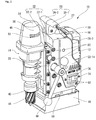
Fig. 1 is a perspective view of a drilling machine according to an embodiment of the present invention as seen from the left front side of the drilling machine. -
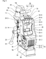
Fig. 2 is a perspective view of the drilling machine shown inFig. 1 , as seen from the right front side of the drilling machine. -
Fig. 3 is a partially sectioned view of the drilling machine shown inFig. 1 . -
Fig. 4 is an exploded view of a body unit of the drilling machine. -
Fig. 5 is a rear perspective view of the drilling machine shown inFig. 1 , with a battery removed therefrom. -
Fig. 6 is a perspective view of the drilling machine shown inFig. 1 , with a drilling drive unit separated from the drilling machine body unit. -
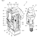
Fig. 7 is a perspective view of the drilling drive unit shown inFig. 6 , as seen from a different angle from that ofFig. 6 . -
Fig. 8 is a perspective view showing the front side of a battery. -
Fig. 9 is a top perspective view of the drilling machine shown inFig. 1 when a battery locking member is in a retracted position. -
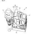
Fig. 10 is a top perspective view of the drilling machine shown inFig. 1 when the battery locking member is in an advanced position. -
Fig. 11 is a circuit block diagram showing a drive control circuit. -
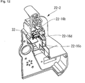
Fig. 12 is a perspective view showing a left-side part of a battery housing. - As shown in
Figs. 1 to 5 , adrilling machine 10 according to an embodiment of the present invention is a battery-operated portable drilling machine including adrilling drive unit 14 having amotor 48 for rotationally driving a drilling tool (cylindrical cutter in the illustrated example) 44 and a drillingmachine body unit 12 having abattery loading part 28 into which is loaded abattery 16 for supplying electric power to themotor 48, the drillingmachine body unit 12 supporting thedrilling drive unit 14 vertically movably to bring thedrilling tool 44 toward and away from a workpiece. Thedrilling machine 10 is secured to a predetermined drilling operation position of a workpiece by an electromagnet-type securing unit 18 attached to the bottom of the drillingmachine body unit 12. In this state, thedrilling tool 44 attached to the lower end of thedrilling drive unit 14 is driven to rotate by themotor 48, and afeed handle 66 attached to the drillingmachine body unit 12 is turned, thereby moving thedrilling drive unit 14 downward relative to the drillingmachine body unit 12 through a gear device comprising arack 64 and apinion 65, and thus drilling the workpiece with thedrilling tool 44. - The drilling
machine body unit 12 has, as shown inFigs. 3 and4 , aframe 20 supporting thedrilling drive unit 14 movably in a vertical direction, and abattery housing 22 attached to theframe 20. More specifically, theframe 20 is formed in an L-shape by a front wall portion 20-1 to which thedrilling drive unit 14 is attached, and a lower wall portion 20-2 to which an electromagnet-type securing unit 18 is attached. Thebattery housing 22, which is attached to the L-shapedframe 20, is configured to constitute abattery loading part 28 in an upper rear part thereof to removably hold abattery 16 therein. Theframe 20 needs to have sufficient strength to support thedrilling drive unit 14, which is subjected to a large load during a drilling operation, and to also support the electromagnet-type securing unit 18. In this embodiment, theframe 20 is made of aluminum to ensure the necessary and sufficient strength. On the other hand, thebattery housing 22 is mainly for supporting thebattery 16 and therefore made of a resin material to achieve a reduction in the overall weight of the drilling machine. In addition, because thebattery housing 22 is made of a resin material, no short circuit occurs even if any of female connector terminals 16-5 (Fig. 8 ) of thebattery 16 contacts thebattery housing 22. It should be noted that the term "L-shaped frame" as used herein means that the structure of theframe 20 contains an L-shaped portion. That is, the term "L-shaped frame" means to include any frame structure containing an L-shaped portion even if the overall configuration is not an L-shape, e.g. a frame structure in which a part of the lower wall portion 20-2 extends forward beyond the front wall portion 20-1. - The
battery housing 22 comprises a right-side part 22-1 and a left-side part 22-2, which are defined by splitting thebattery housing 22 at the center thereof. The right-side part 22-1 and the left-side part 22-2 are attached to theframe 20 in such a manner as to sandwich theframe 20 therebetween from the right and left sides. When thebattery housing 22 is attached to theframe 20, an interior space 24 (Fig. 3 ) is formed between thebattery housing 22 and theframe 20. In theinterior space 24, adrive control circuit 36 is attached to the rear surface of the front wall portion 20-1 in parallel thereto at a position between right- and left-side ribs 20-3 and 20-4 (Fig.4 ). Thedrive control circuit 36 controls electric power supplied from thebattery 16 to themotor 48 of thedrilling drive unit 14 and to an electromagnet 18-1 in the electromagnet-type securing unit 18. - The
battery housing 22 is formed with engagement projecting portions 22-9 to be engaged with circular engagement recesses 20-9, respectively, formed on the right- and left-side ribs 20-3 and 20-4 of theframe 20. Each engagement projecting portion 22-9 comprises 6 projections arranged in a circle. This structure strengthens the engagement between thebattery housing 22 and theframe 20. Thebattery housing 22 is secured to theframe 20 with screws 82 (Fig. 1 ) inserted through screw insertion holes 22-11, respectively, provided in each of a right side 22-14 (Fig. 2 ) and left side 22-15 (Fig. 1 ) of thebattery housing 22, and engaged with 4 threadedholes 21, respectively, provided in each of the right and left sides 20-10 and 20-11 of theframe 20. Further, elongated screws (not shown) are inserted through 6 screw insertion holes 22-12 (Fig. 4 ), respectively, provided in the right-side part 22-1, and engaged with 6 threaded holes 22-13 (Fig. 4 ), respectively, provided in the left-side part 22-2, thereby connecting and securing the right-side part 22-1 and the left-side part 22-2 directly to each other. Thus, thebattery housing 22 is secured to theframe 20 at a large number of points; therefore, stress concentration is less likely to occur even when a large force is applied to thebattery housing 22, and the danger of breakage of thebattery housing 22 is reduced. - The top of the
battery housing 22 is provided with agrip 26. Thegrip 26 comprises, as shown inFig. 4 , a right-side grip portion 26-1 formed on the right-side part 22-1 of thebattery housing 22 and a left-side grip portion 26-2 formed on the left-side part 22-2 of thebattery housing 22. The right-side grip portion 26-1 and the left-side grip portion 26-2 form a grip 26 (Fig. 1 ) when the right-side part 22-1 and the left-side part 22-2 are attached to theframe 20. The right-side grip portion 26-1 and the left-side grip portion 26-2 are connected and secured to each other by an elongated screw 27 (Fig. 2 ) extending from the right-side grip portion 26-1 to the left-side grip portion 26-2. Thescrew 27 functions also as a reinforcing member to increase the strength of thegrip 26. - As shown in
Fig. 3 , adrilling drive unit 14 is attached to the front side of the front wall portion 20-1 of theframe 20. Thedrilling drive unit 14 has adrilling tool 44, such as a drill or a cylindrical cutter, held at the lower side of thedrilling drive unit 14 by being fitted to anarbor 40. Thearbor 40 is connected through aspeed reducer 45 in thedrilling drive unit 14 to amotor 48 provided in amotor cover 46 of thedrilling drive unit 14. Thedrilling tool 44 is driven to rotate by driving themotor 48. As shown inFig. 1 and other figures, themotor cover 46 has a plurality of vent holes 52 provided in side surfaces 50 thereof to cool themotor 48 by air flowing into themotor cover 46 through the vent holes 52. The reason why the vent holes 52 are provided not in atop surface 54 but in the side surfaces 50 is to prevent, as much as possible, water or foreign objects, such as machining swarf and dust, from entering the inside of themotor cover 46. The left side of thedrilling drive unit 14 is provided with aplug 56 serving as a cutting fluid filler port. Theplug 56 is fitted with a connection socket attached to the distal end of a hose extending from a cutting fluid supply tank (not shown) to supply a cutting fluid to thedrilling tool 44 during drilling. - As shown in
Fig. 6 , the front side of the front wall portion 20-1 of theframe 20 has vertically extendingdovetail grooves 62 formed on the right and left sides thereof. On the other hand, thedrilling drive unit 14 is, as shown inFig. 7 , provided with a generally plate-shapedslider 63 having right- and left-side edges shaped to correspond to thedovetail grooves 62. Theslider 63 has a vertically extending rack 64 (Fig. 7 ) provided in the center of the rear side thereof, and theframe 20 is provided with a pinion 65 (Fig. 6 ) to be engaged with therack 64. Thepinion 65 is rotated by manually rotating afeed handle 66 removably attached to an end of theshaft 23 projecting from the right side 20-10 (Fig. 2 ) of theframe 20, thereby vertically moving thedrilling drive unit 14 relative to theframe 20. The feed handle 66 can also be attached to an end of theshaft 23 projecting from the left side 20-11 of theframe 20. Thus, the feed handle 66 can be attached to either of the right and left sides of theframe 20 according to each particular situation. It should be noted that the terms "right" and "left" as used in this specification mean directions relative to thedrilling machine 10 as seen from the front side thereof. -
Wiring 68 extending from themotor 48 of thedrilling drive unit 14 passes through a wiring insertion passage 69 (Figs. 6 and7 ) formed between onedovetail groove 62 and theslider 63 and, as shown inFig. 3 , leads into theinterior space 24 of the drillingmachine body unit 12, in which thewiring 68 is connected to thedrive control circuit 36. Thus, almost no part of thewiring 68 is exposed to the outside. The structure in which thewiring 68 is not exposed to the outside prevents thewiring 68 from being disconnected, for example, by application of an excessively large force thereto which might otherwise occur when thewiring 68 is caught on something. - The electromagnet-
type securing unit 18 attached to the lower side of the drillingmachine body unit 12 is configured such that, when electric power from thebattery 16 is supplied to the electromagnet 18-1 therein, the electromagnet-type securing unit 18 generates a magnetic field and thus magnetically adheres to a workpiece made of a magnetic material, e.g. iron, thereby securely holding thedrilling machine 10 to the workpiece. Aposition adjusting mechanism 58 is provided between the electromagnet-type securing unit 18 and theframe 20 to allow the position of the drillingmachine body unit 12 to be adjusted both the front-back direction and the lateral direction relative to the electromagnet-type securing unit 18 by turning aposition adjusting handle 60 removably attached to theposition adjusting mechanism 58, thereby enabling the drilling position of the workpiece to be finely adjusted. It should be noted that theposition adjusting handle 60 can also be attached to the right side of theposition adjusting mechanism 58. - As shown in
Fig. 1 , the left side 22-15 of thebattery housing 22 is provided with anelectromagnet switch 70 for activating the electromagnet-type securing unit 18. Awall 72 is provided around theelectromagnet switch 70 to prevent theelectromagnet switch 70 from being easily carelessly actuated. Theelectromagnet switch 70 is configured to be turned off by pressing the rear (left as seen inFig. 1 ) end portion thereof. Thewall 72 is raised in height at its rear end portion so that theelectromagnet switch 70 is not easily accidentally turned, particularly from on to off. Further, as shown inFig. 2 , the right side 22-14 of thebattery housing 22 is provided with amotor switch 74 for starting themotor 48. Awall 76 is also provided around themotor switch 74 to prevent themotor switch 74 from being easily carelessly actuated. Thus, theelectromagnet switch 70 and themotor switch 74 are disposed on the different lateral sides 22-15 and 22-14, respectively, of thebattery housing 22. With this structure, it is easy to ensure the areas for placing the switches. In addition, because interference between wiring lines is reduced in theinterior space 24, it is possible to design thebattery housing 22 to be smaller in size. Further, it is possible to prevent, as much as possible, theelectromagnet switch 70 and themotor switch 74 from being actuated mistakenly from each other. - As shown in
Fig. 3 , a limit switch 32 (detailed later) and anLED indicator circuit 34 are disposed in an upper part of theinterior space 24 of thebattery housing 22. Thebattery housing 22 is provided with apartition plate 38 that divides thedrive control circuit 36 from theLED indicator circuit 34 and thelimit switch 32. Thepartition plate 38 separates a lower interior space 24-2, in which thedrive control circuit 36 is disposed, from an upper interior space 24-1, in which theLED indicator circuit 34 and thelimit switch 32 are disposed. Thepartition plate 38 is provided so as to slope downward from the rear toward the front. In addition, a drain port 80 (Fig. 3 ) is provided in a part of the front wall portion 20-1 of theframe 20 that is located in the upper interior space 24-1. The upper interior space 24-1 is not sealed from the outside because the upper interior space 24-1 slidably receives abattery locking member 30, which projects to the outside of thebattery housing 22. Therefore, there is a possibility that water, e.g. rainwater, may enter the upper interior space 24-1 from the outside. However, the above-described structure having the slopedpartition plate 38 and thedrain port 80 makes it possible to discharge water entering the upper interior space 24-1 to the outside from thedrain port 80 without allowing the water to enter the lower interior space 24-2, in which thedrive control circuit 36 is located. Consequently, it is possible to prevent thedrive control circuit 36 from being wet with water, which would otherwise cause a failure. It should be noted that, in this embodiment, thepartition plate 38 comprises, as shown inFig. 4 , a right-side partition plate 38-1 provided in the right-side part 22-1 of thebattery housing 22 and a left-side partition plate 38-2 provided in the left-side part 22-2 of thebattery housing 22. The right-side partition plate 38-1 and the left-side partition plate 38-2 face each other in such a manner as to form an opening therebetween, and thewiring 35 connected to theLED indicator circuit 34 and thelimit switch 32 is vertically passed through the opening. Aseal member 39 is provided around thewiring 35 in the opening to seal between the upper interior space 24-1 and the lower interior space 24-2. - The upper surface of the lower wall portion 20-2 of the
frame 20 slopes downward from the front toward the rear, so that if water should enter the lower interior space 24-2, the water is discharged to the outside from a drain groove 20-13 provided at the rear end of the lower wall portion 20-2. - As shown in
Fig. 5 , thebattery housing 22 of the drillingmachine body unit 12 is formed with a battery accommodating space (battery loading part) 28 for receiving and loading abattery 16 at the rear upper part thereof. That is, thebattery housing 22 is formed with a right-side wall portion 28-3, a left-side wall portion 28-4, an intermediate wall portion 28-1 extending between the right- and left-side wall portions 28-3 and 28-4 apart from and parallel to the front wall portion 20-1 of theframe 20 at the rear of the front wall portion 20-1, and a bottom wall portion 28-2 extending rearward from the lower end edge of the intermediate wall portion 28-1 between the right- and left-side wall portions 28-3 and 28-4. Thebattery accommodating space 28 is defined by the right- and left-side wall portions 28-3 and 28-4, the intermediate wall portion 28-1 and the bottom wall portion 28-2 in such a way that thebattery accommodating space 28 is open at the upper and rear sides thereof. Thebattery accommodating space 28 is provided with battery guides 28-5 extending vertically at right- and left-side positions, respectively, slightly rearward of the intermediate wall portion 28-1. Guide grooves 28-6 are formed between the battery guides 28-5 and the intermediate wall portion 28-1. The guide grooves 28-6 are slidingly engaged with guide rails 16-2 (Fig. 8 ), respectively, of thebattery 16, which are provided to extend vertically on a front side 16-1 of thebattery 16, thereby allowing thebattery 16 to be guided vertically. The intermediate wall portion 28-1 further has male connector terminals 28-7 disposed at a lower position thereof, and a battery locking recess 28-8 disposed at an upper position thereof. On the other hand, the front side 16-1 of thebattery 16 is, as shown inFig. 8 , provided with female connector terminals 16-5 and a battery locking portion 16-4 that is displaceable in the front-back direction and urged forward by a spring member (not shown). When thebattery 16 is loaded into thebattery accommodating space 28 along the battery guides 28-5, the female connector terminals 16-5 engage the male connector terminals 28-7 to make thebattery 16 and thedrive control circuit 36 electrically connected to each other. At the same time, the battery locking portion 16-4 is fitted into the battery locking recess 28-8 to hold thebattery 16 from moving vertically from the loaded position. The battery locking portion 16-4 has a sloped lower surface. When thebattery 16 is slid downward along the battery guides 28-5, the sloped lower surface of the battery locking portion 16-4 is pushed by an upper wall portion 28-9 of the battery locking recess 28-8, causing the battery locking portion 16-4 to retract. After the sloped lower surface of the battery locking portion 16-4 has passed over the upper wall portion 28-9 to the lower side of the latter, the battery locking portion 16-4 is pushed out forward by the spring urging force to fit into the battery locking recess 28-8. Further, in this embodiment, the battery locking portion 16-4 extends upward in thebattery 16 to an inclined surface 16-3 exposed through an opening 16-6a in the widthwise center of an inclined battery holding member engagement surface 16-6 (described later) formed on the top front side of thebattery 16. The inclined surface 16-3 is substantially flush with the battery holding member engagement surface 16-6. When thebattery 16 is to be unloaded from thebattery accommodating space 28, the inclined surface 16-3 is pushed to displace the battery locking portion 16-4 rearward. Thebattery housing 22 has a battery locking member accommodating part 22-16 (Figs. 3 and4 ) formed at the top of the intermediate wall portion 28-1 to extend in the front and back direction and to open rearward. The battery locking member accommodating part 22-16 comprises a top portion 22-16a and a bottom portion 22-16b. The battery locking member accommodating part 22-16 accommodates thebattery locking member 30. Thebattery locking member 30 is slidable in the front and back direction in the battery locking member accommodating part 22-16 between a retracted position (Figs. 5 and9 ) where thebattery locking member 30 is retracted relative to thebattery 16 and an advanced position (Fig. 10 ) where thebattery locking member 30 is advanced relative to thebattery 16. Thebattery locking member 30 has an inclined surface 30-1 on a side thereof facing thebattery 16. When thebattery locking member 30 is in the advanced position shown inFig. 10 , the inclined surface 30-1 abuts against the inclined battery holding member engagement surface 16-6 (Figs. 8 and9 ) formed on the top front side of thebattery 16, thereby holding the battery in thebattery accommodating space 28. - The
drive control circuit 36 is provided in the drillingmachine body unit 12 to control mainly the drive of themotor 48 and the electromagnet-type securing unit 18. As shown inFig. 11 , thedrive control circuit 36 has amain control section 83 having a CPU, anelectromagnet control section 84 controlling the electromagnet-type securing unit 18 on the basis of a control signal from themain control section 83, and amotor control section 85 controlling themotor 48 on the basis of a control signal from themain control section 83. Theelectromagnet control section 84 is equipped with a field-effect transistor (FET). The FET functions as a switching element and sequentially switches on and off electrical conduction between thebattery 16 and the electromagnet 18-1 to convert a direct current from thebattery 16 into a pulse current consisting of a periodic pulse train. Theelectromagnet control section 84 changes the switching timing of the FET so as to modulate the pulse width of the pulse current on the basis of a control signal from themain control section 83, thereby controlling the average electric power to be supplied to the electromagnet-type securing unit 18. That is, theelectromagnet control section 84 uses pulse width modulation (PWM) control to control the average electric power per unit of time to be supplied to the electromagnet-type securing unit 18. In this way, theelectromagnet control section 84 adjusts the average electric power to be supplied to the electromagnet-type securing unit 18 to generate a magnetic force with a magnitude required for each particular situation. Themotor control section 85 is also equipped with a field-effect transistor (FET) in the same way as theelectromagnet control section 84. Themotor control section 85 also uses pulse width modulation to control the average electric power to be supplied to themotor 48. - The
drive control circuit 36 further has a DC/DC converter 86 connected to thebattery 16. The DC/DC converter 86 steps down the voltage of thebattery 16, i.e. 24 V, to a voltage of 5 V, which is supplied as electric power for driving thedrive control circuit 36. Theelectromagnet switch 70 is interposed between thebattery 16 and thedrive control circuit 36. When theelectromagnet switch 70 is off, no electric power is supplied to thedrive control circuit 36, and hence themotor 48 is not driven. Between thebattery 16 and the DC/DC converter 86 is provided an overdischargeprevention circuit section 87 comprising a transistor. When the voltage of thebattery 16 drops below a predetermined value, the overdischargeprevention circuit section 87 breaks the circuit so that no more electric current will flow, thereby preventing deterioration of thebattery 16 due to overdischarge. Thedrive control circuit 36 is further provided with a remaining batterycapacity detection section 88 detecting the remaining capacity of thebattery 16. The remaining batterycapacity detection section 88 detects the remaining capacity of thebattery 16 by measuring the voltage of thebattery 16 and outputs an analog signal corresponding to the value of the measured voltage of thebattery 16. The analog signal is converted into a digital signal by an A/D converter 90 before being sent to themain control section 83. Themain control section 83 controls theelectromagnet control section 84 on the basis of the received battery voltage value to adjust the electric power to be supplied to the electromagnet 18-1. It should be noted that the remaining batterycapacity detection section 88 may be configured to detect the remaining capacity of thebattery 16 by measuring the value of electric current from thebattery 16. Thedrive control circuit 36 is further provided with a motor current detection section 92 for measuring the value of electric current flowing through themotor 48. The motor current detection section 92 outputs an analog signal corresponding to the measured electric current value. The analog signal is converted into a digital signal by an A/D converter 94 before being sent to themain control section 83. Themain control section 83 judges the status of themotor 48 on the basis of the received motor current value and changes the electric power to be supplied to the electromagnet 18-1 or stops themotor 48 according to the judged status of themotor 48. Further, thedrive control circuit 36 is provided with a motor switchstatus monitor circuit 96 monitoring the on/off status of themotor switch 74. In addition, thedrive control circuit 36 is provided with a lateral shiftingdetection circuit 99 configured to stop the drive of themotor 48 when a built-in acceleration sensor detects a large change in position of thedrilling machine 10. - The
limit switch 32 is disposed in the upper interior space 24-1 of theinterior space 24, which is formed between theframe 20 and thebattery housing 22. Thelimit switch 32 is disposed to engage a downwardly projecting switch engaging projection 30-6 provided on a part of thebattery locking member 30 that is located in thebattery housing 22 so that, when thebattery locking member 30 moves between the retracted position and the advanced position, thelimit switch 32 is turned on/off by the switch engaging projection 30-6. Specifically, when thebattery locking member 30 projects toward thebattery 16 to assume the advanced position, the switch engaging projection 30-6 pushes to turn on thelimit switch 32, and, when thebattery locking member 30 retracts from the advanced position to move toward the retracted position, where thebattery locking member 30 is withdrawn into thebattery housing 22, thelimit switch 32 is turned off. Thelimit switch 32 is, as shown inFig. 11 , connected to thedrive control circuit 36 to function as a position detecting device detecting that thebattery locking member 30 has moved between the retracted position and the advanced position. It should be noted that the switch engaging projection 30-6 of thebattery locking member 30 extends downward through an opening 22-16c (Fig. 12 ) provided in a portion of the left-side part 22-2 of thebattery housing 22 that constitutes the bottom portion 22-16b of the battery locking member accommodating part 22-16, thus the switch engaging projection 30-6 being engageable with thelimit switch 32. Further, when thebattery locking member 30 is in the advanced position, the switch engaging projection 30-6 abuts against a rear end surface 22-16d of the opening 22-16c to limit the travel range of thebattery locking member 30 and to prevent thebattery locking member 30 from becoming dislodged from the battery locking member accommodating part 22-16. - The upper interior space 24-1 further has an
LED indicator circuit 34 disposed therein in addition to the above-describedlimit switch 32. TheLED indicator circuit 34 serves as a status indicator indicating the status of thedrilling machine 10. TheLED indicator circuit 34 is connected to thedrive control circuit 36 to indicate a status of thedrilling machine 10 on a status indicator 33 (Fig. 1 ) on the top of thebattery housing 22 according to a signal from thedrive control circuit 36. TheLED indicator circuit 34 has green, yellow and red LEDs and indicates the status of the drilling machine by lighting and blinking of the LEDs, thereby informing the operator of the status of the drilling machine. It should be noted that it is also possible to use a single LED packaged as a single device capable of emitting different colors, in place of a set of discrete green, yellow and red LEDs. - When the
drilling machine 10 is to be started, first, thebattery 16 is loaded into thebattery accommodating space 28 in thebattery housing 22. To load thebattery 16 into thebattery accommodating space 28, thebattery locking member 30 is pushed forward into the drillingmachine body unit 12 so as to move to the retracted position shown inFig. 5 , thereby opening the upper side of thebattery accommodating space 28. Thereafter, thebattery 16 is inserted downward into thebattery accommodating space 28 from the open upper side thereof. Thebattery 16 is moved downward while being guided by the battery guides 28-5 and thus accommodated in the battery accommodating space 28 (Fig. 9 ). At this time, the male connector terminals 28-7 of the drillingmachine body unit 12 and the female connector terminals 16-5 of thebattery 16 are connected to each other, and the battery locking portion 16-4 provided on thebattery 16 engages the battery locking recess 28-8 of the intermediate wall portion 28-1 to hold thebattery 16 from moving. In this way, thebattery 16 is loaded in thebattery accommodating space 28. Next, thebattery locking member 30 is pulled out from the drillingmachine body unit 12 toward thebattery 16 and moved to the advanced position shown inFig. 10 . When thebattery locking member 30 is in the advanced position, the inclined surface 30-1, which is provided on a side of thebattery locking member 30 that faces thebattery 16, abuts against the inclined battery holding member engagement surface 16-6 (Figs. 8 and9 ) formed on the top front side of thebattery 16, thereby holding thebattery 16 in thebattery accommodating space 28. Unloading of thebattery 16 from thebattery housing 22 is carried out by pushing the inclined surface 16-3 of the battery locking portion 16-4 to withdraw the battery locking portion 16-4 into thebattery 16, and in this state, pulling thebattery 16 upward from thebattery accommodating space 28. In this regard, the arrangement is such that, when thebattery locking member 30 is in the advanced position, thebattery 16 cannot be removed by being pulled upward because thebattery locking member 30 interferes with thebattery 16. That is, when thebattery locking member 30 is in the advanced position, a part of thebattery locking member 30 is located in a travel path of thebattery 16 along which thebattery 16 moves when removed from thebattery accommodating space 28 by being pulled upward therefrom; therefore, when thebattery locking member 30 is in the advanced position, thebattery 16 cannot be removed from thebattery housing 22. It is necessary, in order to remove thebattery 16, to push and move thebattery locking member 30 into the drillingmachine body unit 12 to the retracted position shown inFig. 9 , and in this state, to pull out thebattery 16 upwardly. Thus, thebattery locking member 30 limits the movement of thebattery 16, thereby preventing accidental removal of thebattery 16. - When the
battery locking member 30 is pulled out toward thebattery 16 and moved to the advanced position in a state where thebattery 16 is correctly loaded in thebattery accommodating space 28, thebattery 16 is held by thebattery locking member 30 so that thebattery 16 cannot be removed from thebattery accommodating space 28, and thelimit switch 32 is turned on. When theelectromagnet switch 70 is turned on in this state, thedrive control circuit 36 is connected to thebattery 16 and supplied with a power source to start controlling theelectromagnet control section 84 so that themain control section 83 of thedrive control circuit 36 supplies electric power to the electromagnet-type securing unit 18. When supplied with electric power, the electromagnet 18-1 generates a magnetic field and thus magnetically adheres to a workpiece made of a magnetic material at a drilling worksite, thereby securely holding thedrilling machine 10 at the drilling worksite. At the same time, thedrive control circuit 36 detects that thelimit switch 32 is on, and judges that thedrilling machine 10 has been started normally. Thus, thedrive control circuit 36 indicates the present status of thedrilling machine 10 on thestatus indicator 33. Specifically, thedrive control circuit 36 lights up the green LED of theLED indicator circuit 34. On the other hand, when theelectromagnet switch 70 is turned on with thebattery locking member 30 remaining in the retracted position, the electromagnet-type securing unit 18 is driven in the same way as the above, but thedrive control circuit 36 detects that thelimit switch 32 is off, and judges that thedrilling machine 10 has been started with thebattery 16 remaining in a removable state. Accordingly, thedrive control circuit 36 indicates, on thestatus indicator 33, a warning sign to inform the operator that thebattery 16 is in a removable state. Specifically, the red LED of theLED indicator circuit 34 is blinked. If thebattery locking member 30 is moved to the advanced position and thus thelimit switch 32 is turned on in a state where the warning sign is being indicated, the warning state is canceled, and thedrilling machine 10 is determined to be in a normally started state. Accordingly, the green LED of theLED indicator circuit 34 lights up. It should be noted that, when thebattery 16 has not been lowered to the correct loading position in thebattery accommodating space 28 and hence not been loaded correctly, even if thebattery locking member 30 is moved toward the advanced position, the inclined surface 30-1 of thebattery locking member 30 abuts against the battery holding member engagement surface 16-6 of thebattery 16 on the way to the advanced position. Therefore, thebattery locking member 30 cannot reach the advanced position. Accordingly, the limit switch remains off. In other words, when the operator tries to drive thedrilling machine 10 in a state where thebattery 16 has not been loaded correctly in thebattery accommodating space 28, a warning sign is also indicated as stated above; therefore, it is possible to inform the operator that thebattery 16 has not been loaded correctly. - If the
electromagnet switch 70 has been turned on before thebattery 16 is loaded in thebattery accommodating space 28, the electromagnet-type securing unit 18 is driven at the same time as thebattery 16 is loaded. At this time, if themotor switch 74 is off, thedrilling machine 10 is determined to be in a normally started state, and the green LED of theLED indicator circuit 34 is lit up. If themotor switch 74 is on, themotor 48 is not driven, and on thestatus indicator 33, the green LED blinks to inform the operator that themotor switch 74 has been on from the beginning. If, in this state, themotor switch 74 is turned off temporarily, the green LED of thestatus indicator 33 is switched to light up to show that thedrilling machine 10 is in a normally started state. - If the
motor switch 74 is turned on when thedrilling machine 10 is in a normally started state and hence the green LED of theLED indicator circuit 34 is on, themain control section 83 of thedrive control circuit 36 starts to drive themotor 48 through themotor control section 85. If themotor switch 74 is turned off thereafter, thedrive control circuit 36 stops themotor 48. In contrast, when thebattery locking member 30 is not in the advanced position and hence the red LED is blinking to indicate the above-described warning sign on thestatus indicator 33, even if themotor switch 74 is turned on, thedrive control circuit 36 does not drive themotor 48 but continues to indicate the warning sign. If thebattery locking member 30 retracts from the advanced position when themotor 48 is being driven in the normally started state and hence thelimit switch 32 turns from on to off, thedrive control circuit 36 blinks the red LED of theLED indicator circuit 34 to indicate a warning sign on thestatus indicator 33. It should be noted that, at this time, it is possible to reduce the electric power to be supplied to themotor 48 to reduce the rotational speed of themotor 48, or alternatively, it is also possible to stop the supply of electric power to themotor 48 to stop themotor 48. - Thus, the
status indicator 33, which indicates the status of thedrilling machine 10, is configured to indicate some different signs according to the on/off statuses of thelimit switch 32, theelectromagnet switch 70 and themotor switch 74. In thedrilling machine 10 of the present invention, in particular, the securing unit for securely holding the drillingmachine body unit 12 is the electromagnet-type securing unit 18, which uses the electromagnet 18-1. Accordingly, if the supply of electric power to the electromagnet 18-1 is stopped and the force for securely holding the drillingmachine body unit 12 is cancelled suddenly, there is a danger of causing an accident such as the fall or drop of thedrilling machine 10. Therefore, a warning sign is indicated to inform the operator of danger when a state is detected in which removal of thebattery 16 may occur while the electromagnet-type securing unit 18 is being driven. By indicating such a warning sign, the operator is prompted to move thebattery locking member 30 to the advanced position so that removal of thebattery 16 will not occur, thereby making it possible to prevent an accident such as that stated above. It should be noted that thestatus indicator 33 as the status indicator may indicates, in addition to the above-described warning sign, the remaining capacity of thebattery 16 detected by the remaining batterycapacity detection section 88, and the level of load on themotor 48 surmised from the electric current supplied to themotor 48, which is detected by the motor current detection section 92, for example. - The
battery locking member 30 in this embodiment has the function of preventing removal of thebattery 16 from thebattery accommodating space 28, and at the same time, functions as a dustproof cover that covers, from above, a vertically extending gap between the intermediate wall portion 28-1 of thebattery housing 22 and the front side 16-1 of thebattery 16 to prevent the entry of machining swarf, water, etc. into the gap. The function of thebattery locking member 30 as a dustproof cover makes it possible to reduce the danger of machining swarf, water, etc. entering to reach the connector terminals 16-5 and 28-7, which may cause short circuit. - It should be noted that, although in this embodiment visual indication using lighting and blinking of LEDs is employed as the status indicator of the
drilling machine 10, it is also possible to employ audio indication or a combination of visual indication and audio indication. Further, although in this embodiment thebattery locking member 30 is provided to slide in the front and back direction, thebattery locking member 30 may be provided to be movable in other manners. For example, thebattery locking member 30 may pivotally move. Although thebattery locking member 30 is configured to abut against thebattery 16 when thebattery locking member 30 is in the advanced position, thebattery locking member 30 need not abut against thebattery 16 but may be positioned close to thebattery 16. Further, although thelimit switch 32 is employed as a position detecting device for thebattery locking member 30, a sensor of any other form, e.g. an optical switch, may be employed to realize a position detecting device. - drilling machine 10; drilling machine body unit 12; drilling drive unit 14; battery 16; front side 16-1; guide rails 16-2; inclined surface 16-3; battery locking portion 16-4; female connector terminals 16-5; battery holding member engagement surface 16-6; opening 16-6a; electromagnet-type securing unit 18; electromagnet 18-1; frame 20; front wall portion 20-1; lower wall portion 20-2; right-side rib 20-3; left-side rib 20-4; engagement recess 20-9; right side 20-10; left side 20-11; drain groove 20-13; threaded holes 21; battery housing 22; right-side part 22-1; left-side part 22-2; engagement projecting portion 22-9; screw insertion holes 22-11; screw insertion holes 22-12; threaded holes 22-13; right side 22-14; left side 22-15; battery locking member accommodating part 22-16; shaft 23; interior space 24; upper interior space 24-1; lower interior space 24-2; grip 26; right-side grip portion 26-1; left-side grip portion 26-2; screw 27; battery loading part, battery accommodating space 28; intermediate wall portion 28-1; bottom wall portion 28-2; right-side wall portion 28-3; left-side wall portion 28-4; battery guides 28-5; guide grooves 28-6; male connector terminals 28-7; battery locking recess 28-8; upper wall portion 28-9; battery locking member 30; inclined surface 30-1; limit switch 32; status indicator 33; LED indicator circuit 34; wiring 35; drive control circuit 36; partition plate 38; right-side partition plate 38-1; left-side partition plate 38-2; seal member 39; arbor 40; drilling tool 44; speed reducer 45; motor cover 46; motor 48; side surfaces 50; vent holes 52; top surface 54; plug 56; position adjusting mechanism 58; position adjusting handle 60; dovetail grooves 62; slider 63; rack 64; pinion 65; feed handle 66; wiring 68; wiring insertion passage 69; electromagnet switch 70; wall 72; motor switch 74; wall 76; drain port 80; screws 82; main control section 83; electromagnet control section 84; motor control section 85; DC/DC converter 86; overdischarge prevention circuit section 87; remaining battery capacity detection section 88; A/D converter 90; motor current detection section 92; A/D converter 94; motor switch status monitor circuit 96; lateral shifting detection circuit 99
Claims (6)
- A battery-operated drilling machine comprising:a drilling drive unit having a motor for rotationally driving a drilling tool;a drilling machine body unit having a battery loading part into which a battery for supplying electric power to the motor is loaded, the drilling machine body unit supporting the drilling drive unit vertically movably to bring the drilling tool toward and away from a workpiece;a battery locking member attached to the drilling machine body unit, the battery locking member being movable between a retracted position and an advanced position relative to the battery loaded in the battery loading part, the battery locking member being configured to prevent removal of the battery from the battery loading part when the battery locking member is in the advanced position;a position detecting device provided in the drilling machine body unit to detect a position of the battery locking member; anda status indicator for indicating a status of the drilling machine;wherein, when the position detecting device detects a state in which the battery locking member is not in the advanced position when the battery is loaded in the battery loading part, the status indicator indicates a warning sign that indicates the state.
- The drilling machine of claim 1, further comprising:an electromagnet attached to the drilling machine body unit to securely hold the drilling machine body unit to the workpiece;wherein the status indicator indicates the warning sign when the state is detected by the position detecting device while the electromagnet is being driven.
- The drilling machine of claim 1 or 2, further comprising:a drive control circuit controlling drive of the motor;wherein the drive control circuit does not start the motor when the status indicator is indicating the warning sign.
- The drilling machine of claim 3, wherein the drive control circuit stops the motor when the status indicator indicates the warning sign while the motor is being driven.
- The drilling machine of claim 1, wherein the position detecting device has a limit switch, the limit switch being configured to be turned on/off when the battery locking member moves between the retracted position and the advanced position, thereby detecting a position of the battery locking member.
- The drilling machine of claim 1, wherein the status indicator has a light-emitting element, so that the warning is visually indicated by a change in color or in lighting condition of the light-emitting element.
Applications Claiming Priority (2)
| Application Number | Priority Date | Filing Date | Title |
|---|---|---|---|
| JP2013113597A JP5948280B2 (en) | 2013-05-30 | 2013-05-30 | Battery drilling machine |
| PCT/JP2014/064061 WO2014192785A1 (en) | 2013-05-30 | 2014-05-28 | Battery-type drilling machine |
Publications (3)
| Publication Number | Publication Date |
|---|---|
| EP3006144A1 true EP3006144A1 (en) | 2016-04-13 |
| EP3006144A4 EP3006144A4 (en) | 2017-03-15 |
| EP3006144B1 EP3006144B1 (en) | 2025-09-17 |
Family
ID=51988810
Family Applications (1)
| Application Number | Title | Priority Date | Filing Date |
|---|---|---|---|
| EP14803350.9A Active EP3006144B1 (en) | 2013-05-30 | 2014-05-28 | Battery-type drilling machine |
Country Status (7)
| Country | Link |
|---|---|
| EP (1) | EP3006144B1 (en) |
| JP (1) | JP5948280B2 (en) |
| KR (1) | KR101828664B1 (en) |
| CN (1) | CN105246627B (en) |
| AU (1) | AU2014271765B2 (en) |
| TW (1) | TWI547331B (en) |
| WO (1) | WO2014192785A1 (en) |
Families Citing this family (8)
| Publication number | Priority date | Publication date | Assignee | Title |
|---|---|---|---|---|
| US11387514B2 (en) * | 2016-10-18 | 2022-07-12 | Mirai-Labo Kabushiki Kaisha | Power supply device and load monitor |
| JP6565888B2 (en) * | 2016-12-19 | 2019-08-28 | 新東工業株式会社 | Lifting unit |
| CN110832690B (en) * | 2017-02-13 | 2022-09-09 | 创科无线普通合伙 | Rechargeable battery pack |
| WO2018225379A1 (en) * | 2017-06-07 | 2018-12-13 | 株式会社マキタ | Drilling apparatus |
| DE112020004086T5 (en) | 2019-08-28 | 2022-07-07 | Nitto Kohki Co., Ltd. | Portable machine tool |
| WO2021039185A1 (en) * | 2019-08-28 | 2021-03-04 | 日東工器株式会社 | Portable machining tool |
| US11845178B2 (en) | 2020-11-03 | 2023-12-19 | Techtronic Cordless Gp | Modular work station |
| CN113560618B (en) * | 2021-07-29 | 2022-07-22 | 荣成荣盛橡胶机械有限公司 | Directional drilling equipment for drilling angle |
Family Cites Families (22)
| Publication number | Priority date | Publication date | Assignee | Title |
|---|---|---|---|---|
| US2977825A (en) * | 1958-08-20 | 1961-04-04 | Buck Mfg Company | Electromagnetic drill support with auxiliary power supply |
| JPS62123064U (en) * | 1986-01-27 | 1987-08-05 | ||
| JPH0683926B2 (en) * | 1988-07-14 | 1994-10-26 | 岑男 竹内 | Construction machinery used to repair snow-melting nozzles |
| JP3262415B2 (en) | 1993-07-19 | 2002-03-04 | キヤノン株式会社 | Image reading apparatus, surface condition inspection apparatus, and exposure apparatus having the apparatus |
| JP3687173B2 (en) * | 1996-03-08 | 2005-08-24 | 日立工機株式会社 | Cordless power tool |
| JP3545129B2 (en) * | 1996-05-22 | 2004-07-21 | 三洋電機株式会社 | Power supply control circuit for electronic equipment |
| JP3027538B2 (en) * | 1996-05-28 | 2000-04-04 | 日東工器株式会社 | Drilling machine control device |
| JP3442969B2 (en) * | 1997-07-09 | 2003-09-02 | 日東工器株式会社 | Drilling machine |
| WO1999056376A1 (en) * | 1998-04-27 | 1999-11-04 | Mitsubishi Denki Kabushiki Kaisha | Uninterruptible power supply |
| DE19905085A1 (en) * | 1999-01-29 | 2000-08-03 | Black & Decker Inc N D Ges D S | Battery operated, hand-held power tool |
| DE20108167U1 (en) * | 2001-05-15 | 2001-08-30 | Lehrberger, Andreas, 82377 Penzberg | Hand drill with height guide for drilling vertical holes and vertical screwing |
| US7121773B2 (en) * | 2003-08-01 | 2006-10-17 | Nitto Kohki Co., Ltd. | Electric drill apparatus |
| JP4077777B2 (en) * | 2003-08-29 | 2008-04-23 | 日東工器株式会社 | Low length electric drill |
| CN1891414A (en) * | 2005-05-17 | 2007-01-10 | 密尔沃基电动工具公司 | Power tool, battery, charger and method of operating the same |
| US8376667B2 (en) * | 2007-07-27 | 2013-02-19 | Milwaukee Electric Tool Corporation | AC/DC magnetic drill press |
| CN201168806Y (en) * | 2008-03-05 | 2008-12-24 | 王亮 | Electric drill with convenient loading and unloading of battery pack |
| JP5541444B2 (en) * | 2009-12-29 | 2014-07-09 | 日立工機株式会社 | Electric tool |
| TWM386950U (en) * | 2010-04-09 | 2010-08-21 | shun-sheng Lin | Digital display structure for a drilling machine |
| WO2011129733A1 (en) * | 2010-04-16 | 2011-10-20 | Husqvarna Ab | A drilling device with a controller for the feeding unit. |
| CN202028801U (en) * | 2011-01-01 | 2011-11-09 | 牛保明 | Chargeable direct current electric hand drill |
| JP4793515B2 (en) | 2011-04-18 | 2011-10-12 | マックス株式会社 | Battery pack and power tool |
| JP5952777B2 (en) * | 2013-05-29 | 2016-07-13 | 日東工器株式会社 | Battery drilling machine |
-
2013
- 2013-05-30 JP JP2013113597A patent/JP5948280B2/en active Active
-
2014
- 2014-05-28 CN CN201480030153.9A patent/CN105246627B/en active Active
- 2014-05-28 WO PCT/JP2014/064061 patent/WO2014192785A1/en not_active Ceased
- 2014-05-28 AU AU2014271765A patent/AU2014271765B2/en active Active
- 2014-05-28 KR KR1020157036791A patent/KR101828664B1/en active Active
- 2014-05-28 TW TW103118628A patent/TWI547331B/en active
- 2014-05-28 EP EP14803350.9A patent/EP3006144B1/en active Active
Non-Patent Citations (1)
| Title |
|---|
| See references of WO2014192785A1 * |
Also Published As
| Publication number | Publication date |
|---|---|
| KR20160010622A (en) | 2016-01-27 |
| TWI547331B (en) | 2016-09-01 |
| AU2014271765A1 (en) | 2016-01-21 |
| EP3006144A4 (en) | 2017-03-15 |
| AU2014271765B2 (en) | 2016-07-28 |
| KR101828664B1 (en) | 2018-02-12 |
| TW201515741A (en) | 2015-05-01 |
| JP2014231129A (en) | 2014-12-11 |
| EP3006144B1 (en) | 2025-09-17 |
| CN105246627A (en) | 2016-01-13 |
| CN105246627B (en) | 2017-04-12 |
| WO2014192785A1 (en) | 2014-12-04 |
| JP5948280B2 (en) | 2016-07-06 |
Similar Documents
| Publication | Publication Date | Title |
|---|---|---|
| EP3006144B1 (en) | Battery-type drilling machine | |
| AU2014271763B2 (en) | Battery-operated drilling machine | |
| EP3254789B1 (en) | Battery-operated drilling machine | |
| US11179787B2 (en) | Battery adapter for a cutting power tool | |
| US20180205244A1 (en) | Hand-held electric power tool | |
| AU2017202536B2 (en) | Battery-operated drilling machine | |
| JP6224922B2 (en) | Battery drilling machine | |
| CN205303236U (en) | A slip switching mechanism and power transfer switch for power transfer switch | |
| CN217453808U (en) | Electric tool | |
| WO2021039185A1 (en) | Portable machining tool | |
| CN117204916A (en) | Medical electric lithotripter and medical handle |
Legal Events
| Date | Code | Title | Description |
|---|---|---|---|
| PUAI | Public reference made under article 153(3) epc to a published international application that has entered the european phase |
Free format text: ORIGINAL CODE: 0009012 |
|
| 17P | Request for examination filed |
Effective date: 20151130 |
|
| AK | Designated contracting states |
Kind code of ref document: A1 Designated state(s): AL AT BE BG CH CY CZ DE DK EE ES FI FR GB GR HR HU IE IS IT LI LT LU LV MC MK MT NL NO PL PT RO RS SE SI SK SM TR |
|
| AX | Request for extension of the european patent |
Extension state: BA ME |
|
| DAX | Request for extension of the european patent (deleted) | ||
| A4 | Supplementary search report drawn up and despatched |
Effective date: 20170213 |
|
| RIC1 | Information provided on ipc code assigned before grant |
Ipc: B23B 45/02 20060101AFI20170207BHEP Ipc: B23B 47/00 20060101ALI20170207BHEP Ipc: H01M 2/10 20060101ALI20170207BHEP |
|
| STAA | Information on the status of an ep patent application or granted ep patent |
Free format text: STATUS: EXAMINATION IS IN PROGRESS |
|
| 17Q | First examination report despatched |
Effective date: 20211203 |
|
| GRAP | Despatch of communication of intention to grant a patent |
Free format text: ORIGINAL CODE: EPIDOSNIGR1 |
|
| STAA | Information on the status of an ep patent application or granted ep patent |
Free format text: STATUS: GRANT OF PATENT IS INTENDED |
|
| RIC1 | Information provided on ipc code assigned before grant |
Ipc: H01M 50/262 20210101ALI20250318BHEP Ipc: H01M 50/247 20210101ALI20250318BHEP Ipc: B23B 45/02 20060101AFI20250318BHEP |
|
| INTG | Intention to grant announced |
Effective date: 20250411 |
|
| GRAS | Grant fee paid |
Free format text: ORIGINAL CODE: EPIDOSNIGR3 |
|
| GRAA | (expected) grant |
Free format text: ORIGINAL CODE: 0009210 |
|
| STAA | Information on the status of an ep patent application or granted ep patent |
Free format text: STATUS: THE PATENT HAS BEEN GRANTED |
|
| AK | Designated contracting states |
Kind code of ref document: B1 Designated state(s): AL AT BE BG CH CY CZ DE DK EE ES FI FR GB GR HR HU IE IS IT LI LT LU LV MC MK MT NL NO PL PT RO RS SE SI SK SM TR |
|
| REG | Reference to a national code |
Ref country code: GB Ref legal event code: FG4D |
|
| REG | Reference to a national code |
Ref country code: CH Ref legal event code: EP |
|
| REG | Reference to a national code |
Ref country code: IE Ref legal event code: FG4D |
|
| REG | Reference to a national code |
Ref country code: DE Ref legal event code: R096 Ref document number: 602014092399 Country of ref document: DE |
|
| PG25 | Lapsed in a contracting state [announced via postgrant information from national office to epo] |
Ref country code: NO Free format text: LAPSE BECAUSE OF FAILURE TO SUBMIT A TRANSLATION OF THE DESCRIPTION OR TO PAY THE FEE WITHIN THE PRESCRIBED TIME-LIMIT Effective date: 20251217 |
|
| REG | Reference to a national code |
Ref country code: LT Ref legal event code: MG9D |
|
| PG25 | Lapsed in a contracting state [announced via postgrant information from national office to epo] |
Ref country code: FI Free format text: LAPSE BECAUSE OF FAILURE TO SUBMIT A TRANSLATION OF THE DESCRIPTION OR TO PAY THE FEE WITHIN THE PRESCRIBED TIME-LIMIT Effective date: 20250917 |
|
| PG25 | Lapsed in a contracting state [announced via postgrant information from national office to epo] |
Ref country code: HR Free format text: LAPSE BECAUSE OF FAILURE TO SUBMIT A TRANSLATION OF THE DESCRIPTION OR TO PAY THE FEE WITHIN THE PRESCRIBED TIME-LIMIT Effective date: 20250917 |
|
| PG25 | Lapsed in a contracting state [announced via postgrant information from national office to epo] |
Ref country code: GR Free format text: LAPSE BECAUSE OF FAILURE TO SUBMIT A TRANSLATION OF THE DESCRIPTION OR TO PAY THE FEE WITHIN THE PRESCRIBED TIME-LIMIT Effective date: 20251218 |
|
| PG25 | Lapsed in a contracting state [announced via postgrant information from national office to epo] |
Ref country code: SE Free format text: LAPSE BECAUSE OF FAILURE TO SUBMIT A TRANSLATION OF THE DESCRIPTION OR TO PAY THE FEE WITHIN THE PRESCRIBED TIME-LIMIT Effective date: 20250917 |
|
| REG | Reference to a national code |
Ref country code: NL Ref legal event code: MP Effective date: 20250917 |
|
| PG25 | Lapsed in a contracting state [announced via postgrant information from national office to epo] |
Ref country code: LV Free format text: LAPSE BECAUSE OF FAILURE TO SUBMIT A TRANSLATION OF THE DESCRIPTION OR TO PAY THE FEE WITHIN THE PRESCRIBED TIME-LIMIT Effective date: 20250917 |
|
| PG25 | Lapsed in a contracting state [announced via postgrant information from national office to epo] |
Ref country code: BG Free format text: LAPSE BECAUSE OF FAILURE TO SUBMIT A TRANSLATION OF THE DESCRIPTION OR TO PAY THE FEE WITHIN THE PRESCRIBED TIME-LIMIT Effective date: 20250917 |
|
| PG25 | Lapsed in a contracting state [announced via postgrant information from national office to epo] |
Ref country code: RS Free format text: LAPSE BECAUSE OF FAILURE TO SUBMIT A TRANSLATION OF THE DESCRIPTION OR TO PAY THE FEE WITHIN THE PRESCRIBED TIME-LIMIT Effective date: 20251217 |
|
| PG25 | Lapsed in a contracting state [announced via postgrant information from national office to epo] |
Ref country code: NL Free format text: LAPSE BECAUSE OF FAILURE TO SUBMIT A TRANSLATION OF THE DESCRIPTION OR TO PAY THE FEE WITHIN THE PRESCRIBED TIME-LIMIT Effective date: 20250917 |
|
| REG | Reference to a national code |
Ref country code: AT Ref legal event code: MK05 Ref document number: 1837909 Country of ref document: AT Kind code of ref document: T Effective date: 20250917 |
|
| PG25 | Lapsed in a contracting state [announced via postgrant information from national office to epo] |
Ref country code: SM Free format text: LAPSE BECAUSE OF FAILURE TO SUBMIT A TRANSLATION OF THE DESCRIPTION OR TO PAY THE FEE WITHIN THE PRESCRIBED TIME-LIMIT Effective date: 20250917 |
|
| PG25 | Lapsed in a contracting state [announced via postgrant information from national office to epo] |
Ref country code: ES Free format text: LAPSE BECAUSE OF FAILURE TO SUBMIT A TRANSLATION OF THE DESCRIPTION OR TO PAY THE FEE WITHIN THE PRESCRIBED TIME-LIMIT Effective date: 20250917 |
|
| PG25 | Lapsed in a contracting state [announced via postgrant information from national office to epo] |
Ref country code: AT Free format text: LAPSE BECAUSE OF FAILURE TO SUBMIT A TRANSLATION OF THE DESCRIPTION OR TO PAY THE FEE WITHIN THE PRESCRIBED TIME-LIMIT Effective date: 20250917 |
|
| PG25 | Lapsed in a contracting state [announced via postgrant information from national office to epo] |
Ref country code: IT Free format text: LAPSE BECAUSE OF FAILURE TO SUBMIT A TRANSLATION OF THE DESCRIPTION OR TO PAY THE FEE WITHIN THE PRESCRIBED TIME-LIMIT Effective date: 20250917 |
|
| PG25 | Lapsed in a contracting state [announced via postgrant information from national office to epo] |
Ref country code: IS Free format text: LAPSE BECAUSE OF FAILURE TO SUBMIT A TRANSLATION OF THE DESCRIPTION OR TO PAY THE FEE WITHIN THE PRESCRIBED TIME-LIMIT Effective date: 20260117 |
|
| PG25 | Lapsed in a contracting state [announced via postgrant information from national office to epo] |
Ref country code: CZ Free format text: LAPSE BECAUSE OF FAILURE TO SUBMIT A TRANSLATION OF THE DESCRIPTION OR TO PAY THE FEE WITHIN THE PRESCRIBED TIME-LIMIT Effective date: 20250917 Ref country code: PT Free format text: LAPSE BECAUSE OF FAILURE TO SUBMIT A TRANSLATION OF THE DESCRIPTION OR TO PAY THE FEE WITHIN THE PRESCRIBED TIME-LIMIT Effective date: 20260119 |
|
| PG25 | Lapsed in a contracting state [announced via postgrant information from national office to epo] |
Ref country code: PL Free format text: LAPSE BECAUSE OF FAILURE TO SUBMIT A TRANSLATION OF THE DESCRIPTION OR TO PAY THE FEE WITHIN THE PRESCRIBED TIME-LIMIT Effective date: 20250917 |
|
| PG25 | Lapsed in a contracting state [announced via postgrant information from national office to epo] |
Ref country code: SK Free format text: LAPSE BECAUSE OF FAILURE TO SUBMIT A TRANSLATION OF THE DESCRIPTION OR TO PAY THE FEE WITHIN THE PRESCRIBED TIME-LIMIT Effective date: 20250917 Ref country code: EE Free format text: LAPSE BECAUSE OF FAILURE TO SUBMIT A TRANSLATION OF THE DESCRIPTION OR TO PAY THE FEE WITHIN THE PRESCRIBED TIME-LIMIT Effective date: 20250917 |
|
| REG | Reference to a national code |
Ref country code: DE Ref legal event code: R097 Ref document number: 602014092399 Country of ref document: DE |
|
| PG25 | Lapsed in a contracting state [announced via postgrant information from national office to epo] |
Ref country code: LT Free format text: LAPSE BECAUSE OF FAILURE TO SUBMIT A TRANSLATION OF THE DESCRIPTION OR TO PAY THE FEE WITHIN THE PRESCRIBED TIME-LIMIT Effective date: 20250917 |
|
| PG25 | Lapsed in a contracting state [announced via postgrant information from national office to epo] |
Ref country code: DK Free format text: LAPSE BECAUSE OF FAILURE TO SUBMIT A TRANSLATION OF THE DESCRIPTION OR TO PAY THE FEE WITHIN THE PRESCRIBED TIME-LIMIT Effective date: 20250917 |
|
| PGFP | Annual fee paid to national office [announced via postgrant information from national office to epo] |
Ref country code: GB Payment date: 20260522 Year of fee payment: 13 |
|
| PGFP | Annual fee paid to national office [announced via postgrant information from national office to epo] |
Ref country code: DE Payment date: 20260522 Year of fee payment: 13 |
|
| PLBE | No opposition filed within time limit |
Free format text: ORIGINAL CODE: 0009261 |
|
| STAA | Information on the status of an ep patent application or granted ep patent |
Free format text: STATUS: NO OPPOSITION FILED WITHIN TIME LIMIT |
|
| REG | Reference to a national code |
Ref country code: CH Ref legal event code: L10 Free format text: ST27 STATUS EVENT CODE: U-0-0-L10-L00 (AS PROVIDED BY THE NATIONAL OFFICE) Effective date: 20260729 |