EP3006124B1 - Work roll manufactured by laser cladding and method therefor - Google Patents
Work roll manufactured by laser cladding and method therefor Download PDFInfo
- Publication number
- EP3006124B1 EP3006124B1 EP14188249.8A EP14188249A EP3006124B1 EP 3006124 B1 EP3006124 B1 EP 3006124B1 EP 14188249 A EP14188249 A EP 14188249A EP 3006124 B1 EP3006124 B1 EP 3006124B1
- Authority
- EP
- European Patent Office
- Prior art keywords
- substrate
- composition
- layer
- rest
- laser
- Prior art date
- Legal status (The legal status is an assumption and is not a legal conclusion. Google has not performed a legal analysis and makes no representation as to the accuracy of the status listed.)
- Active
Links
Images


Classifications
-
- C—CHEMISTRY; METALLURGY
- C22—METALLURGY; FERROUS OR NON-FERROUS ALLOYS; TREATMENT OF ALLOYS OR NON-FERROUS METALS
- C22C—ALLOYS
- C22C38/00—Ferrous alloys, e.g. steel alloys
- C22C38/18—Ferrous alloys, e.g. steel alloys containing chromium
- C22C38/24—Ferrous alloys, e.g. steel alloys containing chromium with vanadium
-
- B—PERFORMING OPERATIONS; TRANSPORTING
- B23—MACHINE TOOLS; METAL-WORKING NOT OTHERWISE PROVIDED FOR
- B23K—SOLDERING OR UNSOLDERING; WELDING; CLADDING OR PLATING BY SOLDERING OR WELDING; CUTTING BY APPLYING HEAT LOCALLY, e.g. FLAME CUTTING; WORKING BY LASER BEAM
- B23K26/00—Working by laser beam, e.g. welding, cutting or boring
- B23K26/34—Laser welding for purposes other than joining
-
- B—PERFORMING OPERATIONS; TRANSPORTING
- B23—MACHINE TOOLS; METAL-WORKING NOT OTHERWISE PROVIDED FOR
- B23K—SOLDERING OR UNSOLDERING; WELDING; CLADDING OR PLATING BY SOLDERING OR WELDING; CUTTING BY APPLYING HEAT LOCALLY, e.g. FLAME CUTTING; WORKING BY LASER BEAM
- B23K35/00—Rods, electrodes, materials, or media, for use in soldering, welding, or cutting
- B23K35/02—Rods, electrodes, materials, or media, for use in soldering, welding, or cutting characterised by mechanical features, e.g. shape
- B23K35/0222—Rods, electrodes, materials, or media, for use in soldering, welding, or cutting characterised by mechanical features, e.g. shape for use in soldering or brazing
- B23K35/0244—Powders, particles or spheres; Preforms made therefrom
-
- B—PERFORMING OPERATIONS; TRANSPORTING
- B23—MACHINE TOOLS; METAL-WORKING NOT OTHERWISE PROVIDED FOR
- B23K—SOLDERING OR UNSOLDERING; WELDING; CLADDING OR PLATING BY SOLDERING OR WELDING; CUTTING BY APPLYING HEAT LOCALLY, e.g. FLAME CUTTING; WORKING BY LASER BEAM
- B23K35/00—Rods, electrodes, materials, or media, for use in soldering, welding, or cutting
- B23K35/22—Rods, electrodes, materials, or media, for use in soldering, welding, or cutting characterised by the composition or nature of the material
- B23K35/24—Selection of soldering or welding materials proper
- B23K35/30—Selection of soldering or welding materials proper with the principal constituent melting at less than 1550°C
- B23K35/3053—Fe as the principal constituent
-
- C—CHEMISTRY; METALLURGY
- C22—METALLURGY; FERROUS OR NON-FERROUS ALLOYS; TREATMENT OF ALLOYS OR NON-FERROUS METALS
- C22C—ALLOYS
- C22C38/00—Ferrous alloys, e.g. steel alloys
- C22C38/02—Ferrous alloys, e.g. steel alloys containing silicon
-
- C—CHEMISTRY; METALLURGY
- C22—METALLURGY; FERROUS OR NON-FERROUS ALLOYS; TREATMENT OF ALLOYS OR NON-FERROUS METALS
- C22C—ALLOYS
- C22C38/00—Ferrous alloys, e.g. steel alloys
- C22C38/04—Ferrous alloys, e.g. steel alloys containing manganese
-
- C—CHEMISTRY; METALLURGY
- C22—METALLURGY; FERROUS OR NON-FERROUS ALLOYS; TREATMENT OF ALLOYS OR NON-FERROUS METALS
- C22C—ALLOYS
- C22C38/00—Ferrous alloys, e.g. steel alloys
- C22C38/12—Ferrous alloys, e.g. steel alloys containing tungsten, tantalum, molybdenum, vanadium, or niobium
-
- C—CHEMISTRY; METALLURGY
- C22—METALLURGY; FERROUS OR NON-FERROUS ALLOYS; TREATMENT OF ALLOYS OR NON-FERROUS METALS
- C22C—ALLOYS
- C22C38/00—Ferrous alloys, e.g. steel alloys
- C22C38/18—Ferrous alloys, e.g. steel alloys containing chromium
- C22C38/22—Ferrous alloys, e.g. steel alloys containing chromium with molybdenum or tungsten
-
- C—CHEMISTRY; METALLURGY
- C22—METALLURGY; FERROUS OR NON-FERROUS ALLOYS; TREATMENT OF ALLOYS OR NON-FERROUS METALS
- C22C—ALLOYS
- C22C38/00—Ferrous alloys, e.g. steel alloys
- C22C38/18—Ferrous alloys, e.g. steel alloys containing chromium
- C22C38/40—Ferrous alloys, e.g. steel alloys containing chromium with nickel
- C22C38/44—Ferrous alloys, e.g. steel alloys containing chromium with nickel with molybdenum or tungsten
-
- C—CHEMISTRY; METALLURGY
- C22—METALLURGY; FERROUS OR NON-FERROUS ALLOYS; TREATMENT OF ALLOYS OR NON-FERROUS METALS
- C22C—ALLOYS
- C22C38/00—Ferrous alloys, e.g. steel alloys
- C22C38/18—Ferrous alloys, e.g. steel alloys containing chromium
- C22C38/40—Ferrous alloys, e.g. steel alloys containing chromium with nickel
- C22C38/46—Ferrous alloys, e.g. steel alloys containing chromium with nickel with vanadium
-
- C—CHEMISTRY; METALLURGY
- C22—METALLURGY; FERROUS OR NON-FERROUS ALLOYS; TREATMENT OF ALLOYS OR NON-FERROUS METALS
- C22C—ALLOYS
- C22C38/00—Ferrous alloys, e.g. steel alloys
- C22C38/18—Ferrous alloys, e.g. steel alloys containing chromium
- C22C38/40—Ferrous alloys, e.g. steel alloys containing chromium with nickel
- C22C38/48—Ferrous alloys, e.g. steel alloys containing chromium with nickel with niobium or tantalum
-
- C—CHEMISTRY; METALLURGY
- C22—METALLURGY; FERROUS OR NON-FERROUS ALLOYS; TREATMENT OF ALLOYS OR NON-FERROUS METALS
- C22C—ALLOYS
- C22C38/00—Ferrous alloys, e.g. steel alloys
- C22C38/18—Ferrous alloys, e.g. steel alloys containing chromium
- C22C38/40—Ferrous alloys, e.g. steel alloys containing chromium with nickel
- C22C38/50—Ferrous alloys, e.g. steel alloys containing chromium with nickel with titanium or zirconium
-
- B—PERFORMING OPERATIONS; TRANSPORTING
- B23—MACHINE TOOLS; METAL-WORKING NOT OTHERWISE PROVIDED FOR
- B23K—SOLDERING OR UNSOLDERING; WELDING; CLADDING OR PLATING BY SOLDERING OR WELDING; CUTTING BY APPLYING HEAT LOCALLY, e.g. FLAME CUTTING; WORKING BY LASER BEAM
- B23K2101/00—Articles made by soldering, welding or cutting
- B23K2101/34—Coated articles ; Surface treated articles
-
- B—PERFORMING OPERATIONS; TRANSPORTING
- B23—MACHINE TOOLS; METAL-WORKING NOT OTHERWISE PROVIDED FOR
- B23K—SOLDERING OR UNSOLDERING; WELDING; CLADDING OR PLATING BY SOLDERING OR WELDING; CUTTING BY APPLYING HEAT LOCALLY, e.g. FLAME CUTTING; WORKING BY LASER BEAM
- B23K2103/00—Materials to be soldered, welded or cut
- B23K2103/02—Iron or ferrous alloys
- B23K2103/04—Steel or steel alloys
-
- B—PERFORMING OPERATIONS; TRANSPORTING
- B23—MACHINE TOOLS; METAL-WORKING NOT OTHERWISE PROVIDED FOR
- B23K—SOLDERING OR UNSOLDERING; WELDING; CLADDING OR PLATING BY SOLDERING OR WELDING; CUTTING BY APPLYING HEAT LOCALLY, e.g. FLAME CUTTING; WORKING BY LASER BEAM
- B23K2103/00—Materials to be soldered, welded or cut
- B23K2103/02—Iron or ferrous alloys
- B23K2103/04—Steel or steel alloys
- B23K2103/05—Stainless steel
-
- B—PERFORMING OPERATIONS; TRANSPORTING
- B23—MACHINE TOOLS; METAL-WORKING NOT OTHERWISE PROVIDED FOR
- B23K—SOLDERING OR UNSOLDERING; WELDING; CLADDING OR PLATING BY SOLDERING OR WELDING; CUTTING BY APPLYING HEAT LOCALLY, e.g. FLAME CUTTING; WORKING BY LASER BEAM
- B23K2103/00—Materials to be soldered, welded or cut
- B23K2103/18—Dissimilar materials
Definitions
- the present invention is related to the field of manufacturing work rolls intended for hot and cold mills, and preferably intended for strip rolling mills.
- the invention is more specifically related to work rolls obtained by the laser-cladding method.
- Laser cladding is a surface-processing technology involving the deposition of a material of different nature on a metal substrate using a laser beam.
- Cladding consumables are deposited in either wire or powder form transported by an inert gas, injected into the molten pool, either laterally or coaxially to the laser beam, melted and consolidated by use of the laser, in order to coat part of the substrate. It is often used to improve mechanical properties, to provide higher wear resistance, heat resistance or higher hardness or to increase corrosion resistance.
- HSM hot strip mills
- Document US 2002/0165634 A1 discloses a laser-assisted, direct metal deposition (DMD tm ), preferably in a closed-loop arrangement, used to fabricate designed articles and components such as molds and tools with improved properties.
- a laminate substrate or structure is provided having a surface onto which a layer of a material is deposited having the desired characteristic using the laser-assisted DMD process.
- the substrate/layer combination may be tailored for improved wear resistance, thermal conductivity, density/hardness, corrosion and/or resistance to corrosion, oxidation or other desirable effects.
- the layer of material may be tailored to have a phase which is different from that of the substrate.
- the layer material itself may be chosen to promote a phase which is different from that of the substrate.
- the outer layer(s) of material may be fabricated using a robotic closed-loop DMD arrangement.
- Document WO 2013/113853 A1 discloses a method for laser cladding a rotation symmetric steel rolling mill roll substrate with a wear and corrosion resistant metal coating made of at least two layers, a first nickel alloy coating layer as an intermediate layer and a second cobalt alloy coating layer as a top layer. The method comprises the steps of:
- the invention also relates to a rolling mill roll steel substrate provided with such wear and corrosion resistant metal coatings.
- the cobalt alloy comprises (in mass percentage) between 27 and 32% Cr, 4 to 6% W, 0.9 to 1.4% C, 1 to 2 % Fe, 1 to 3% Ni, up to 1% Mn, up to 1% Mo, up to 0.1% B, up to 0.01% O, up to 0.02% S, and balance Co and inevitable impurities; and that, in the intermediate layer, the nickel alloy comprises between 15 to 17% Mo, 14.5 to 16.5% Cr, 4 to 7% Fe, 3-4.5% W, up to 2% Mn, up to 0.1% C, up to 0.05% P, up to 0.02% S, up to 0.5% V and balance Ni and inevitable impurities.
- This method with built-up intermediate layer allows to suppress constraints in the external layer, which otherwise would suffer cracks.
- the cylinder axe used as a substrate is made of cast iron and the external layers have a total thickness of 1-2 mm.
- Document EP 0 070 773 A1 relates to the manufacture of metal parts whose heart and surface should have different characteristics. It first provides a method of manufacturing a composite metal part by coating or reloading of a metal core of low-alloy structural steel, by means of a harder metal layer consisting of a high speed steel, chromium-tungsten steel, chromium-molybdenum steel or chromium steel combined with several elements such as : tungsten, molybdenum, vanadium, cobalt, this process being characterized in that the high speed steel has a hardness greater than 57 Rockwell C, in that the low-alloyed steel which constitutes the metal core is selected so as to be compatible with said high speed steel, in that said steel is exclusively provided in the form of a pre-alloyed powder, and in that the coating or the reloading of the core by this powder is achieved by means of one of the following group of welding processes : by means of a welding torch with transferred arc plasma, or semi-transferred
- the present invention aims to provide work rolls, particularly intended for hot rolling mills, which exhibit improved resistance to thermal fatigue as well as to surface degradation.
- the invention also aims to provide work rolls having a coating with very high quality without cracks or porosities.
- the present invention relates to a method for manufacturing a rolling mill roll, preferably a hot rolling mill roll, by laser cladding a reusable steel axe substrate having a rotational symmetry axis with a metal coating external layer, said metal coating external layer having a work tool steel composition, comprising the steps of :
- the method is further limited by one or a suitable combination of the following features:
- the present invention relates to a method for manufacturing a rolling mill roll.
- the present invention relates to a new laser-cladding method for coating a roll having a steel axe (or shaft or spindle) substrate with a deposition of a "layer" of hot or cold work tool steel, which can be obtained from the deposit of successive sublayers.
- Tool steels used are similar to HSS WR grades and/or with higher carbide content.
- the composition of the steel axe comprises 0.2-0.5% C and 0.5 - 5% Cr, 0-1% Mo, 0-1% Mn and 0-0.4% Si, with preferably 0.4% C and 1-2% Cr, the rest being Fe and the inevitable impurities.
- the deposited layer typically has a work tool steel composition depending on the type of cylinder, whether it is a hot work roll or a cold work roll.
- the composition of the top layer for a work roll consists of 0.5-3.5% C, 2-18% Cr, 0.5-7% Mo, 0.5-8% V, 0.2-5% W, 0-5% Nb, 0-1% Ti, 0.5-1% Mn, 0.2-3% Si and 0-3% Ni, the rest being Fe and the inevitable impurities.
- the composition of the top layer for the manufacturing of a hot work roll is consisting of 1-3 % C, 4-18% Cr, 0.5-7% Mo, 0.5-8% V, 0.2-5% W, 1-5% Nb, 0-1% Ti, 0.5-1% Mn and 0.2-0.5% Si, the rest being Fe and inevitable impurities.
- the composition of the top layer for the manufacturing of a hot work roll is consisting of 1-3.5% C, 2-7% Cr, 1-7% Mo, 1-8% V and 0.2-5% W, 0-5% Nb, 0.5-1% Mn, 0.2-3% Si and 1-3% Ni, the rest being Fe and inevitable impurities.
- the composition of the top layer for the manufacturing of a cold work roll is consisting of 0.5-2% C, 5-13% Cr, 0.5-5% Mo, 0.5-5% V, 0.2-5% W, 0.5-1% Mn and 0.2-0.5% Si, the rest being Fe and the inevitable impurities.
- the coating achieved by laser cladding in the present invention exhibits a very fine microstructure (10-15 ⁇ m or ten times finer than a spun-cast HSS tool steel (see Fig.1 ) and even finer than a CPC (continuous pour cladding) - obtained steel - 30-150 ⁇ m (see Scandella F.; Développement d'un acierer pour le rewin de cylindres de laminage àedge Soudage et Technique Connexes, Mars-Avril 2010, pp. 35-46)); see also comparison with powder metallurgy steels : two times coarser, Fig.2 ).
- the microstructure is characteristic of tempered martensite with carbides (M 2 C, MC and M 23 C 6 ). The thermal treatment necessary for softening the martensite and precipitate the carbides is made at 500-650°C.
- top layer tool steel material (HSS) obtained by the laser-cladding method of the present invention exhibits an improved behaviour in surface degradation, a very good adherence to the substrate, a refined microstructure carbides network size (10x finer than in spin-casting, only 2x coarser than in powder metallurgy).
- the method typically provides a laser-cladding 20mm thick shell of tool steel on reusable steel axe, similar roll life as with prior art but strongly increased roll campaign (5X) thus increased productivity, higher Young modulus (130-170 GPa cast iron vs 200-230 GPa steel) and less roll flattening and bending, reduced variation of roll diameter and tool steel materials with very similar machinability as in prior art.
- the thermal treatment is shortened as compared with the method of prior art, thus economizing energy and more environment-friendly.
Landscapes
- Chemical & Material Sciences (AREA)
- Engineering & Computer Science (AREA)
- Mechanical Engineering (AREA)
- Materials Engineering (AREA)
- Metallurgy (AREA)
- Organic Chemistry (AREA)
- Physics & Mathematics (AREA)
- Optics & Photonics (AREA)
- Plasma & Fusion (AREA)
- Laser Beam Processing (AREA)
- Heat Treatment Of Articles (AREA)
- Reduction Rolling/Reduction Stand/Operation Of Reduction Machine (AREA)
Description
- The present invention is related to the field of manufacturing work rolls intended for hot and cold mills, and preferably intended for strip rolling mills. The invention is more specifically related to work rolls obtained by the laser-cladding method.
- In order to meet high productivity and surface quality requirements of their customers, manufacturers of work rolls for rolling mills are lead to explore different materials submitted to increasingly harsh specifications. Under normal hot operating conditions, the table of the working cylinder has to withstand wear and hot thermal fatigue induced by the periodicity of its fast cooling and reheating at each turn of the cylinder. Such cylinders, that are required to have a very tough and wear-resistant surface while having a ductile core cylinder, can be manufactured by various techniques, among which spin or centrifugal casting, which is the conventional method, laser cladding or powder metallurgy by hot isostatic pressing of a shell built up to a steel core.
- In cold rolling, roll degradation mainly occurs due to abrasive wear leading to loss of roughness. For achieving adequate roughness retention and strip cleanliness, a hard chromium plating is applied. Today, HSS rolls are used with satisfactory results in roughness retention but strip cleanliness is still inadequate.
- Laser cladding is a surface-processing technology involving the deposition of a material of different nature on a metal substrate using a laser beam. Cladding consumables are deposited in either wire or powder form transported by an inert gas, injected into the molten pool, either laterally or coaxially to the laser beam, melted and consolidated by use of the laser, in order to coat part of the substrate. It is often used to improve mechanical properties, to provide higher wear resistance, heat resistance or higher hardness or to increase corrosion resistance.
- Work rolls for hot strip mills (HSM) are usually manufactured using the spin-casting method followed by a heat treatment. The roll is constituted by a cast or forged iron or steel core with an external shell of highly alloyed steel grade, which composition comprises high carbon, Mn, Si and elements generating carbides, such as W, Mo, V, Cr, Co, etc.
- Document
US 2002/0165634 A1 discloses a laser-assisted, direct metal deposition (DMDtm), preferably in a closed-loop arrangement, used to fabricate designed articles and components such as molds and tools with improved properties. A laminate substrate or structure is provided having a surface onto which a layer of a material is deposited having the desired characteristic using the laser-assisted DMD process. In different embodiments, the substrate/layer combination may be tailored for improved wear resistance, thermal conductivity, density/hardness, corrosion and/or resistance to corrosion, oxidation or other desirable effects. Alternatively, the layer of material may be tailored to have a phase which is different from that of the substrate. In particular, the layer material itself may be chosen to promote a phase which is different from that of the substrate. To enhance throughput, the outer layer(s) of material may be fabricated using a robotic closed-loop DMD arrangement. - Document
WO 2013/113853 A1 discloses a method for laser cladding a rotation symmetric steel rolling mill roll substrate with a wear and corrosion resistant metal coating made of at least two layers, a first nickel alloy coating layer as an intermediate layer and a second cobalt alloy coating layer as a top layer. The method comprises the steps of: - a) cleaning the substrate by machining the surface of the substrate;
- b) rotating the substrate around its axis of rotational symmetry;
- c) forming a melt pool on the surface of the rotating substrate by means of a laser beam and applying the first coating layer by feeding a first powder material into the melt pool, wherein the first powder material is fed into the melt pool coaxially with the laser beam;
- d) forming a melt pool on the surface of the substrate provided with the first coating layer by means of the laser beam and applying the second coating layer by feeding a second powder material into the melt pool, wherein the second powder material is fed into the melt pool coaxially with the laser beam.
- The invention also relates to a rolling mill roll steel substrate provided with such wear and corrosion resistant metal coatings.
- Moreover, this document teaches that, in the top layer, the cobalt alloy comprises (in mass percentage) between 27 and 32% Cr, 4 to 6% W, 0.9 to 1.4% C, 1 to 2 % Fe, 1 to 3% Ni, up to 1% Mn, up to 1% Mo, up to 0.1% B, up to 0.01% O, up to 0.02% S, and balance Co and inevitable impurities; and that, in the intermediate layer, the nickel alloy comprises between 15 to 17% Mo, 14.5 to 16.5% Cr, 4 to 7% Fe, 3-4.5% W, up to 2% Mn, up to 0.1% C, up to 0.05% P, up to 0.02% S, up to 0.5% V and balance Ni and inevitable impurities.
- This method with built-up intermediate layer allows to suppress constraints in the external layer, which otherwise would suffer cracks.
- The cylinder axe used as a substrate is made of cast iron and the external layers have a total thickness of 1-2 mm.
-
Document EP 0 070 773 A1 relates to the manufacture of metal parts whose heart and surface should have different characteristics. It first provides a method of manufacturing a composite metal part by coating or reloading of a metal core of low-alloy structural steel, by means of a harder metal layer consisting of a high speed steel, chromium-tungsten steel, chromium-molybdenum steel or chromium steel combined with several elements such as : tungsten, molybdenum, vanadium, cobalt, this process being characterized in that the high speed steel has a hardness greater than 57 Rockwell C, in that the low-alloyed steel which constitutes the metal core is selected so as to be compatible with said high speed steel, in that said steel is exclusively provided in the form of a pre-alloyed powder, and in that the coating or the reloading of the core by this powder is achieved by means of one of the following group of welding processes : by means of a welding torch with transferred arc plasma, or semi-transferred, by means of a laser welding torch, the coating or weld recharging operation being followed by a heat treatment. - The present invention aims to provide work rolls, particularly intended for hot rolling mills, which exhibit improved resistance to thermal fatigue as well as to surface degradation.
- The invention also aims to provide work rolls having a coating with very high quality without cracks or porosities.
- The present invention relates to a method for manufacturing a rolling mill roll, preferably a hot rolling mill roll, by laser cladding a reusable steel axe substrate having a rotational symmetry axis with a metal coating external layer, said metal coating external layer having a work tool steel composition, comprising the steps of :
- rotating the reusable substrate around its axis of rotational symmetry;
- effecting a laser cladding on the rotating substrate, by forming a melt pool on the surface of the rotating substrate by means of a laser beam and affixing the coating layer by feeding a powder material into the laser-induced melt pool,
- submitting the coated substrate to a thermal treatment made of a tempering treatment comprising a heating up to a temperature in the range 500-650°C followed by a holding at this temperature during a time comprised between 2 and 5 hours, in order to soften martensite and precipitate carbides;
wherein the composition for said metal coating external layer is consisting of 0.5-3.5% C, 2-18% Cr, 0.5-7% Mo, 0.5-8% V, 0.2-5% W, 0-5% Nb, 0-1% Ti, 0.5-1% Mn, 0.2-3% Si and 0-3% Ni, the rest being Fe and inevitable impurities;
wherein a preheating of the substrate is performed, thanks to a coating head combining induction heating with laser cladding process;
wherein the cladding rate is in the range from 2.35 kg/h to 18 kg/h, and
wherein said external coating layer is made of multiple added coating sublayers and has a total thickness comprised between 1 and 30 mm, the thickness of each single external coating sublayer being comprised between 0.1 and 2.5 mm. - According to preferred embodiments of the invention, the method is further limited by one or a suitable combination of the following features:
- the composition for said metal coating external layer is consisting of 1-3 % C, 4-18% Cr, 0.5-7% Mo, 0.5-8% V, 0.2-5% W, 1-5% Nb, 0-1% Ti, 0.5-1% Mn and 0.2-0.5% Si, the rest being Fe and inevitable impurities;
- the composition for said metal coating external layer is consisting of 1-3.5% C, 2-7% Cr, 1-7% Mo, 1-8% V, 0.2-5% W, 0-5% Nb, 0.5-1% Mn, 0.2-3% Si and 1-3% Ni, the rest being Fe and inevitable impurities;
- the composition for said metal coating external layer is consisting of 0.5-2% C, 5-13% Cr, 0.5-5% Mo, 0.5-5% V, 0.2-2% W, 0.5-1% Mn and 0.2-0.5% Si, the rest being Fe and inevitable impurities;
- the composition of the steel axe consists of 0.2-0.5% C and 0.5-5% Cr, 0-1 % Mo, 0-1% Mn and 0-0.4% Si, the rest being Fe and the inevitable impurities;
- the composition of the steel axe contains 0.4% C and 1-2% Cr;
- the method comprises a preliminary step of preparing the reusable substrate by cleaning or machining the surface of the reusable substrate.
- The present invention relates to a method for manufacturing a rolling mill roll.
-
-
Figure 1 represents the microstructure of laser-clad specimens obtained according to the present invention (left) compared with specimens obtained by the prior-art spin-casting method (right). -
Figure 2 represents the microstructure of laser-clad specimens obtained according to the present invention (bottom) compared with specimens obtained by the prior-art powder metallurgy method (top). -
Figure 3A shows thermal fatigue cracks on micrographs of laser-clad HSS (top left), spun-cast HSS (top right) and laser-clad high-carbide steels (bottom) samples, respectively after work roll degradation tests. -
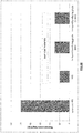
Figure 3.B represents a diagram corresponding toFig.3A showing compared thermal cracks length of spun-cast and different laser-clad samples. - The present invention relates to a new laser-cladding method for coating a roll having a steel axe (or shaft or spindle) substrate with a deposition of a "layer" of hot or cold work tool steel, which can be obtained from the deposit of successive sublayers. Tool steels used are similar to HSS WR grades and/or with higher carbide content.
- The composition of the steel axe comprises 0.2-0.5% C and 0.5 - 5% Cr, 0-1% Mo, 0-1% Mn and 0-0.4% Si, with preferably 0.4% C and 1-2% Cr, the rest being Fe and the inevitable impurities.
- The deposited layer typically has a work tool steel composition depending on the type of cylinder, whether it is a hot work roll or a cold work roll.
- According to the invention, the composition of the top layer for a work roll consists of 0.5-3.5% C, 2-18% Cr, 0.5-7% Mo, 0.5-8% V, 0.2-5% W, 0-5% Nb, 0-1% Ti, 0.5-1% Mn, 0.2-3% Si and 0-3% Ni, the rest being Fe and the inevitable impurities.
- According to a first preferred embodiment of the invention, the composition of the top layer for the manufacturing of a hot work roll is consisting of 1-3 % C, 4-18% Cr, 0.5-7% Mo, 0.5-8% V, 0.2-5% W, 1-5% Nb, 0-1% Ti, 0.5-1% Mn and 0.2-0.5% Si, the rest being Fe and inevitable impurities.
- According to a second preferred embodiment of the invention, the composition of the top layer for the manufacturing of a hot work roll is consisting of 1-3.5% C, 2-7% Cr, 1-7% Mo, 1-8% V and 0.2-5% W, 0-5% Nb, 0.5-1% Mn, 0.2-3% Si and 1-3% Ni, the rest being Fe and inevitable impurities.
- According to a third preferred embodiment of the invention, the composition of the top layer for the manufacturing of a cold work roll is consisting of 0.5-2% C, 5-13% Cr, 0.5-5% Mo, 0.5-5% V, 0.2-5% W, 0.5-1% Mn and 0.2-0.5% Si, the rest being Fe and the inevitable impurities.
- The characteristics of the laser-cladding method used in the present invention are the following:
- high metallurgical bonding;
- low or no porosity and benefit of a high cooling rate leading to very fine microstructure;
- homogeneous composition;
- coating thickness : 0.1-2.5 mm per (sub)layer;
- thicker coatings obtained by adding multiple layers, the thickness of the total external layer being comprised between 1 and 30 mm, and preferably about 20 mm;
- cladding rate from 2.35 kg/h to 18 kg/h with special heads (combination of induction heating with laser-cladding process);
- pre-heating of substrate when necessary;
- post-thermal treatment (e.g. tempering).
- For example, with a composition of 1% C, 4% Cr, 5% Mo, 3% V and 6.5% W, results showed that the quality of the bonding zone is very satisfactory in terms of cracks and porosities.
- One of the advantages is that the coating achieved by laser cladding in the present invention exhibits a very fine microstructure (10-15 µm or ten times finer than a spun-cast HSS tool steel (see
Fig.1 ) and even finer than a CPC (continuous pour cladding) - obtained steel - 30-150 µm (see Scandella F.; Développement d'un acier rapide pour le revêtement de cylindres de laminage à chaud Soudage et Technique Connexes, Mars-Avril 2010, pp. 35-46)); see also comparison with powder metallurgy steels : two times coarser,Fig.2 ). The microstructure is characteristic of tempered martensite with carbides (M2C, MC and M23C6). The thermal treatment necessary for softening the martensite and precipitate the carbides is made at 500-650°C. - Laboratory tests of work roll degradation on a three-disk wear machine simulating the rolling conditions of the early stands of a HSM are shown on
Figs.3A and3B . Cracks in laser-clad HSS were 3 to 5 times shorter than in spun-cast HSS. - In conclusion, top layer tool steel material (HSS) obtained by the laser-cladding method of the present invention exhibits an improved behaviour in surface degradation, a very good adherence to the substrate, a refined microstructure carbides network size (10x finer than in spin-casting, only 2x coarser than in powder metallurgy). In the case of finishing work rolls, the method typically provides a laser-cladding 20mm thick shell of tool steel on reusable steel axe, similar roll life as with prior art but strongly increased roll campaign (5X) thus increased productivity, higher Young modulus (130-170 GPa cast iron vs 200-230 GPa steel) and less roll flattening and bending, reduced variation of roll diameter and tool steel materials with very similar machinability as in prior art.
- Moreover in the method according to the invention, the thermal treatment is shortened as compared with the method of prior art, thus economizing energy and more environment-friendly.
Claims (8)
- A method for manufacturing a rolling mill roll by laser cladding a reusable steel axe substrate having a rotational symmetry axis with a metal coating external layer, said metal coating external layer having a work tool steel composition, comprising the steps of :- rotating the reusable substrate around its axis of rotational symmetry;- effecting a laser cladding on the rotating substrate, by forming a melt pool on the surface of the rotating substrate by means of a laser beam and affixing the coating layer by feeding a powder material into the laser-induced melt pool;- submitting the coated substrate to a thermal treatment made of a tempering treatment comprising a heating up to a temperature in the range 500-650°C followed by a holding at this temperature during a time comprised between 2 and 5 hours, in order to soften martensite and precipitate carbides;
wherein the composition for said metal coating external layer is consisting of 0.5-3.5% C, 2-18% Cr, 0.5-7% Mo, 0.5-8% V, 0.2-5% W, 0-5% Nb, 0-1% Ti, 0.5-1% Mn, 0.2-3% Si and 0-3% Ni, the rest being Fe and inevitable impurities; wherein a preheating of the substrate is performed, thanks to a coating head combining induction heating with laser cladding process;
wherein the cladding rate is in the range from 2.35 kg/h to 18 kg/h; and wherein said external coating layer is made of multiple added coated sublayers and has a total thickness comprised between 1 and 30 mm, the thickness of each single external coating sublayer being comprised between 0.1 and 2.5 mm. - The method of Claim 1, wherein the composition for said metal coating external layer is consisting of 1-3 % C, 4-18% Cr, 0.5-7% Mo, 0.5-8% V, 0.2-5% W, 1-5% Nb, 0-1% Ti, 0.5-1% Mn and 0.2-0.5% Si, the rest being Fe and inevitable impurities.
- The method of Claim 1, wherein the composition for said metal coating external layer is consisting of 1-3.5% C, 2-7% Cr, 1-7% Mo, 1-8% V, 0.2-5% W, 0-5% Nb, 0.5-1% Mn, 0.2-3% Si and 1-3% Ni, the rest being Fe and inevitable impurities.
- The method of Claim 1, wherein the composition for said metal coating external layer is consisting of 0.5-2% C, 5-13% Cr, 0.5-5% Mo, 0.5-5% V, 0.2-2% W, 0.5-1% Mn and 0.2-0.5% Si, the rest being Fe and inevitable impurities.
- The method of Claim 1, wherein the composition of the steel axe comprises 0.2-0.5% C and 0.5-5% Cr, 0-1% Mo, 0-1% Mn and 0-0.4% Si, the rest being Fe and the inevitable impurities.
- The method of Claim 5, wherein the composition of the steel axe comprises 0.4% C and 1-2% Cr.
- The method of Claim 1, wherein it comprises a preliminary step of preparing the reusable substrate by cleaning or machining the surface of the reusable substrate.
- The method of Claim 1, wherein it is a method for manufacturing a hot rolling mill roll.
Priority Applications (6)
| Application Number | Priority Date | Filing Date | Title |
|---|---|---|---|
| EP14188249.8A EP3006124B1 (en) | 2014-10-09 | 2014-10-09 | Work roll manufactured by laser cladding and method therefor |
| SI201430656T SI3006124T1 (en) | 2014-10-09 | 2014-10-09 | Work roll manufactured by laser cladding and method therefor |
| ES14188249.8T ES2661397T3 (en) | 2014-10-09 | 2014-10-09 | Work roller manufactured by laser coating and method for this |
| PL14188249T PL3006124T3 (en) | 2014-10-09 | 2014-10-09 | Work roll manufactured by laser cladding and method therefor |
| EP15778274.9A EP3204173B1 (en) | 2014-10-09 | 2015-10-07 | Method for manufactured a rolling mill roll by laser cladding |
| PCT/EP2015/073189 WO2016055545A1 (en) | 2014-10-09 | 2015-10-07 | Work roll manufactured by laser cladding and method therefor |
Applications Claiming Priority (1)
| Application Number | Priority Date | Filing Date | Title |
|---|---|---|---|
| EP14188249.8A EP3006124B1 (en) | 2014-10-09 | 2014-10-09 | Work roll manufactured by laser cladding and method therefor |
Publications (2)
| Publication Number | Publication Date |
|---|---|
| EP3006124A1 EP3006124A1 (en) | 2016-04-13 |
| EP3006124B1 true EP3006124B1 (en) | 2017-12-20 |
Family
ID=51702991
Family Applications (2)
| Application Number | Title | Priority Date | Filing Date |
|---|---|---|---|
| EP14188249.8A Active EP3006124B1 (en) | 2014-10-09 | 2014-10-09 | Work roll manufactured by laser cladding and method therefor |
| EP15778274.9A Active EP3204173B1 (en) | 2014-10-09 | 2015-10-07 | Method for manufactured a rolling mill roll by laser cladding |
Family Applications After (1)
| Application Number | Title | Priority Date | Filing Date |
|---|---|---|---|
| EP15778274.9A Active EP3204173B1 (en) | 2014-10-09 | 2015-10-07 | Method for manufactured a rolling mill roll by laser cladding |
Country Status (5)
| Country | Link |
|---|---|
| EP (2) | EP3006124B1 (en) |
| ES (1) | ES2661397T3 (en) |
| PL (1) | PL3006124T3 (en) |
| SI (1) | SI3006124T1 (en) |
| WO (1) | WO2016055545A1 (en) |
Cited By (1)
| Publication number | Priority date | Publication date | Assignee | Title |
|---|---|---|---|---|
| WO2022079108A1 (en) | 2020-10-13 | 2022-04-21 | Centre De Recherches Métallurgiques ASBL | Method of manufacturing a hot rolling mill roll by laser cladding |
Families Citing this family (21)
| Publication number | Priority date | Publication date | Assignee | Title |
|---|---|---|---|---|
| WO2019056227A1 (en) * | 2017-09-20 | 2019-03-28 | 杭州巨星科技股份有限公司 | Tool with cutting edge and manufacturing method thereof |
| CN108130490A (en) * | 2017-12-24 | 2018-06-08 | 谢涛 | Novel material for manufacturing pinch roll and manufacturing process thereof |
| JP7185211B2 (en) * | 2018-02-07 | 2022-12-07 | 住友重機械ハイマテックス株式会社 | Tool material manufacturing method and tool material |
| CN109913766B (en) * | 2019-04-09 | 2020-12-25 | 东北大学 | 50Cr6Ni2Y alloy steel powder for laser additive manufacturing and preparation method thereof |
| CN110129674B (en) * | 2019-05-21 | 2020-07-31 | 北京工业大学 | Gradient material steel rail frog prepared by laser cladding |
| CN110344048B (en) * | 2019-07-17 | 2021-06-22 | 株洲辉锐增材制造技术有限公司 | Laser cladding layer of high manganese steel frog and preparation method thereof, and high manganese steel frog |
| CN111471993B (en) * | 2020-05-29 | 2021-06-29 | 燕山大学 | Laser cladding repair material and remanufacturing method for sintering four-roller four-roller crusher |
| WO2022003189A1 (en) * | 2020-07-02 | 2022-01-06 | Oerlikon Surface Solutions Ag, Pfäffikon | Method to produce high corrosion and wear resistant cast iron components by using laser cladding |
| CN112935239B (en) * | 2021-01-14 | 2024-04-05 | 僖昴晰(上海)新材料有限公司 | High hardness welding alloy and composition thereof |
| CN113106450A (en) * | 2021-03-03 | 2021-07-13 | 泉州市双滢新材料科技有限公司 | Composite hard coating cutter and preparation method thereof |
| CN113305505A (en) * | 2021-05-11 | 2021-08-27 | 宝武装备智能科技有限公司 | Method for manufacturing cold-rolled hard-surface process roller |
| CN113337814A (en) * | 2021-06-04 | 2021-09-03 | 安徽晨光高耐磨科技股份有限公司 | Preparation method of loop roller on long material rolling production line and loop roller |
| CN113621895B (en) * | 2021-08-18 | 2022-09-30 | 沈阳大陆激光工程技术有限公司 | Laser cladding manufactured cold-rolled deburring roller functional layer alloy powder and preparation method thereof |
| CN115558843A (en) * | 2021-09-08 | 2023-01-03 | 僖昴晰(上海)新材料有限公司 | Alloy steel composition |
| CN113832462B (en) * | 2021-09-24 | 2023-06-27 | 河钢股份有限公司承德分公司 | Laser cladding composite deburring roller and preparation method thereof |
| CN114540811A (en) * | 2022-02-28 | 2022-05-27 | 河北恒韧增材制造有限公司 | Process method for preparing hot-rolled functional plate and roller by microbeam plasma fusion |
| CN114657478B (en) * | 2022-05-23 | 2022-10-25 | 中国长江三峡集团有限公司 | Corrosion-resistant cladding layer powder material and preparation method of cladding layer |
| CN115233116B (en) * | 2022-07-22 | 2023-12-12 | 中钢集团邢台机械轧辊有限公司 | Preparation method of finished product rack working roll suitable for high-strength steel rolling |
| CN115537806A (en) * | 2022-10-19 | 2022-12-30 | 北京赛亿科技有限公司 | A kind of manufacturing process of anti-nodulation hearth roller |
| CN116555660B (en) * | 2023-05-15 | 2025-07-25 | 江苏特维克科技有限公司 | Wear-resistant alloy layer for laser cladding of inner wall of coal dust conveying elbow and additive manufacturing process of wear-resistant alloy layer |
| CN116855937B (en) * | 2023-08-08 | 2024-10-15 | 山东镭研激光科技有限公司 | Cutting pick and method for preparing cutting pick by laser cladding |
Family Cites Families (10)
| Publication number | Priority date | Publication date | Assignee | Title |
|---|---|---|---|---|
| FR2509640A1 (en) * | 1981-07-17 | 1983-01-21 | Creusot Loire | PROCESS FOR PRODUCING A COMPOSITE METAL PART AND PRODUCTS OBTAINED |
| AU650271B2 (en) * | 1990-06-13 | 1994-06-16 | Nippon Steel Corporation | Composite roll for use in rolling and manufacture thereof |
| US5514065A (en) * | 1993-03-31 | 1996-05-07 | Hitachi Metals, Ltd. | Wear- and seizing-resistant roll for hot rolling and method of making the roll |
| JP3944612B2 (en) * | 1996-06-19 | 2007-07-11 | 日立金属株式会社 | Roll for assembly type rolling |
| FR2767725B1 (en) * | 1997-09-01 | 1999-10-08 | Jean Claude Werquin | COMPOSITE WORKING CYLINDER FOR HOT & COLD ROLLING IN HIGH CARBON AND HIGH VANADIUM STEEL AND ITS MANUFACTURING METHOD BY CENTRIFUGAL CASTING |
| US20020165634A1 (en) | 2000-03-16 | 2002-11-07 | Skszek Timothy W. | Fabrication of laminate tooling using closed-loop direct metal deposition |
| WO2013113853A1 (en) | 2012-01-31 | 2013-08-08 | Tata Steel Uk Ltd | Method of laser cladding a rotation symmetric steel rolling mill with two layers; corresponding roll mill roll |
| JP5487376B2 (en) * | 2012-02-28 | 2014-05-07 | 富士高周波工業株式会社 | Laser cladding method and tool material |
| CN103614731A (en) * | 2013-12-02 | 2014-03-05 | 湖州市银鑫轧辊有限公司 | Composite roller repairing method using laser rapid prototyping |
| CN104087866B (en) * | 2014-07-31 | 2016-04-06 | 宁国市宁武耐磨材料有限公司 | A kind of ball mill high heat-resistant and wear-resistant ball |
-
2014
- 2014-10-09 ES ES14188249.8T patent/ES2661397T3/en active Active
- 2014-10-09 SI SI201430656T patent/SI3006124T1/en unknown
- 2014-10-09 PL PL14188249T patent/PL3006124T3/en unknown
- 2014-10-09 EP EP14188249.8A patent/EP3006124B1/en active Active
-
2015
- 2015-10-07 EP EP15778274.9A patent/EP3204173B1/en active Active
- 2015-10-07 WO PCT/EP2015/073189 patent/WO2016055545A1/en not_active Ceased
Non-Patent Citations (1)
| Title |
|---|
| BRÜCKNER FRANK ET AL: "Innovations in laser cladding and direct metal deposition", HIGH POWER LASER MATERIALS PROCESSING: LASERS, BEAM DELIVERY, DIAGNOSTICS, AND APPLICATIONS, SPIE, 1000 20TH ST. BELLINGHAM WA 98225-6705 USA, vol. 8239, no. 1, 9 February 2012 (2012-02-09), pages 1 - 6, XP060001580, DOI: 10.1117/12.906706 * |
Cited By (1)
| Publication number | Priority date | Publication date | Assignee | Title |
|---|---|---|---|---|
| WO2022079108A1 (en) | 2020-10-13 | 2022-04-21 | Centre De Recherches Métallurgiques ASBL | Method of manufacturing a hot rolling mill roll by laser cladding |
Also Published As
| Publication number | Publication date |
|---|---|
| WO2016055545A1 (en) | 2016-04-14 |
| ES2661397T3 (en) | 2018-03-28 |
| EP3204173B1 (en) | 2019-07-17 |
| EP3006124A1 (en) | 2016-04-13 |
| EP3204173A1 (en) | 2017-08-16 |
| PL3006124T3 (en) | 2018-06-29 |
| SI3006124T1 (en) | 2018-10-30 |
Similar Documents
| Publication | Publication Date | Title |
|---|---|---|
| EP3204173B1 (en) | Method for manufactured a rolling mill roll by laser cladding | |
| US12623303B2 (en) | Method for manufacturing a work roll by laser cladding | |
| US4484959A (en) | Process for the production of a composite metal part and products thus obtained | |
| EP3034902B1 (en) | Brake disc and method of manufacturing the same | |
| EP2076352B1 (en) | Refractory metal tooling for friction stir welding comprising a shoulder made of tantalum, niobium or hafnium alloy and a coated or treated surface | |
| EP0309587B1 (en) | Abrasion-resistant composite roll and process for its production | |
| CN111945156A (en) | Method for preparing centrifugal roller through laser cladding | |
| CN104294268B (en) | A kind of wear-resisting deflector roll preparation method | |
| CN114763609B (en) | Wear-resistant shaft sleeve coating and preparation method thereof | |
| WO2013113853A1 (en) | Method of laser cladding a rotation symmetric steel rolling mill with two layers; corresponding roll mill roll | |
| JP6474885B2 (en) | Anvil for rotary cutting unit that is layered | |
| CN109183025A (en) | Wear-resisting Cr8Mo2SiV steel part and preparation method and be used for Cr8Mo2The Ni based wear-resistant alloy powder of SiV steel | |
| CN110004372B (en) | High-temperature-resistant, oxidation-resistant and wear-resistant metallurgical roller and preparation method thereof | |
| CN115142061B (en) | Preparation method of wear-resistant high-speed steel composite roller | |
| CN106676518A (en) | Laser remanufacturing method for metal structural part | |
| JP2571377B2 (en) | Roll for continuous casting of an arb leave type | |
| CN119913505B (en) | A method for improving the wear resistance of rivet heads in automotive hinge riveting machines | |
| KR102843784B1 (en) | High-hardness alloy materials for additive manufacturing and their components | |
| KR100245471B1 (en) | Composite roll for metal rolling and manufacturing method thereof | |
| JP2785139B2 (en) | Composite roll for rolling and manufacturing method thereof | |
| JPH03207510A (en) | Build-up weld roll and its manufacture | |
| JP2000158020A (en) | Composite roll for iron manufacturing rolling equipment, excellent in impact resistance and corrosion resistanve | |
| CN117396294A (en) | Method for producing a guide roller, and corresponding guide roller and wire rolling machine | |
| US20050208279A1 (en) | Items made of wear resistant materials | |
| CN114669906A (en) | A kind of welding wire raw material and preparation method of gradient coating on the surface of continuous casting roll |
Legal Events
| Date | Code | Title | Description |
|---|---|---|---|
| PUAI | Public reference made under article 153(3) epc to a published international application that has entered the european phase |
Free format text: ORIGINAL CODE: 0009012 |
|
| AK | Designated contracting states |
Kind code of ref document: A1 Designated state(s): AL AT BE BG CH CY CZ DE DK EE ES FI FR GB GR HR HU IE IS IT LI LT LU LV MC MK MT NL NO PL PT RO RS SE SI SK SM TR |
|
| AX | Request for extension of the european patent |
Extension state: BA ME |
|
| 17P | Request for examination filed |
Effective date: 20161013 |
|
| RBV | Designated contracting states (corrected) |
Designated state(s): AL AT BE BG CH CY CZ DE DK EE ES FI FR GB GR HR HU IE IS IT LI LT LU LV MC MK MT NL NO PL PT RO RS SE SI SK SM TR |
|
| REG | Reference to a national code |
Ref country code: DE Ref legal event code: R079 Ref document number: 602014018679 Country of ref document: DE Free format text: PREVIOUS MAIN CLASS: B21B0027000000 Ipc: B23K0101340000 |
|
| RIC1 | Information provided on ipc code assigned before grant |
Ipc: C22C 38/24 20060101ALI20170619BHEP Ipc: B23K 103/04 20060101ALI20170619BHEP Ipc: C22C 38/22 20060101ALI20170619BHEP Ipc: B23K 103/18 20060101ALI20170619BHEP Ipc: C22C 38/48 20060101ALI20170619BHEP Ipc: B23K 26/34 20140101ALI20170619BHEP Ipc: C22C 38/12 20060101ALI20170619BHEP Ipc: C22C 38/46 20060101ALI20170619BHEP Ipc: C22C 38/02 20060101ALI20170619BHEP Ipc: B23K 35/02 20060101ALI20170619BHEP Ipc: C22C 38/44 20060101ALI20170619BHEP Ipc: C22C 38/50 20060101ALI20170619BHEP Ipc: C22C 38/04 20060101ALI20170619BHEP Ipc: B23K 35/30 20060101ALI20170619BHEP Ipc: B23K 101/34 20060101AFI20170619BHEP |
|
| GRAP | Despatch of communication of intention to grant a patent |
Free format text: ORIGINAL CODE: EPIDOSNIGR1 |
|
| INTG | Intention to grant announced |
Effective date: 20170828 |
|
| GRAS | Grant fee paid |
Free format text: ORIGINAL CODE: EPIDOSNIGR3 |
|
| GRAA | (expected) grant |
Free format text: ORIGINAL CODE: 0009210 |
|
| AK | Designated contracting states |
Kind code of ref document: B1 Designated state(s): AL AT BE BG CH CY CZ DE DK EE ES FI FR GB GR HR HU IE IS IT LI LT LU LV MC MK MT NL NO PL PT RO RS SE SI SK SM TR |
|
| RAP1 | Party data changed (applicant data changed or rights of an application transferred) |
Owner name: CENTRE DE RECHERCHES METALLURGIQUES ASBL - CENTRUM |
|
| REG | Reference to a national code |
Ref country code: GB Ref legal event code: FG4D |
|
| REG | Reference to a national code |
Ref country code: CH Ref legal event code: EP |
|
| REG | Reference to a national code |
Ref country code: IE Ref legal event code: FG4D |
|
| REG | Reference to a national code |
Ref country code: AT Ref legal event code: REF Ref document number: 955926 Country of ref document: AT Kind code of ref document: T Effective date: 20180115 |
|
| REG | Reference to a national code |
Ref country code: DE Ref legal event code: R096 Ref document number: 602014018679 Country of ref document: DE |
|
| REG | Reference to a national code |
Ref country code: ES Ref legal event code: FG2A Ref document number: 2661397 Country of ref document: ES Kind code of ref document: T3 Effective date: 20180328 |
|
| REG | Reference to a national code |
Ref country code: SE Ref legal event code: TRGR |
|
| REG | Reference to a national code |
Ref country code: NL Ref legal event code: MP Effective date: 20171220 |
|
| PG25 | Lapsed in a contracting state [announced via postgrant information from national office to epo] |
Ref country code: LT Free format text: LAPSE BECAUSE OF FAILURE TO SUBMIT A TRANSLATION OF THE DESCRIPTION OR TO PAY THE FEE WITHIN THE PRESCRIBED TIME-LIMIT Effective date: 20171220 Ref country code: NO Free format text: LAPSE BECAUSE OF FAILURE TO SUBMIT A TRANSLATION OF THE DESCRIPTION OR TO PAY THE FEE WITHIN THE PRESCRIBED TIME-LIMIT Effective date: 20180320 Ref country code: FI Free format text: LAPSE BECAUSE OF FAILURE TO SUBMIT A TRANSLATION OF THE DESCRIPTION OR TO PAY THE FEE WITHIN THE PRESCRIBED TIME-LIMIT Effective date: 20171220 |
|
| REG | Reference to a national code |
Ref country code: LT Ref legal event code: MG4D |
|
| PG25 | Lapsed in a contracting state [announced via postgrant information from national office to epo] |
Ref country code: RS Free format text: LAPSE BECAUSE OF FAILURE TO SUBMIT A TRANSLATION OF THE DESCRIPTION OR TO PAY THE FEE WITHIN THE PRESCRIBED TIME-LIMIT Effective date: 20171220 Ref country code: LV Free format text: LAPSE BECAUSE OF FAILURE TO SUBMIT A TRANSLATION OF THE DESCRIPTION OR TO PAY THE FEE WITHIN THE PRESCRIBED TIME-LIMIT Effective date: 20171220 Ref country code: BG Free format text: LAPSE BECAUSE OF FAILURE TO SUBMIT A TRANSLATION OF THE DESCRIPTION OR TO PAY THE FEE WITHIN THE PRESCRIBED TIME-LIMIT Effective date: 20180320 Ref country code: HR Free format text: LAPSE BECAUSE OF FAILURE TO SUBMIT A TRANSLATION OF THE DESCRIPTION OR TO PAY THE FEE WITHIN THE PRESCRIBED TIME-LIMIT Effective date: 20171220 Ref country code: GR Free format text: LAPSE BECAUSE OF FAILURE TO SUBMIT A TRANSLATION OF THE DESCRIPTION OR TO PAY THE FEE WITHIN THE PRESCRIBED TIME-LIMIT Effective date: 20180321 |
|
| PG25 | Lapsed in a contracting state [announced via postgrant information from national office to epo] |
Ref country code: NL Free format text: LAPSE BECAUSE OF FAILURE TO SUBMIT A TRANSLATION OF THE DESCRIPTION OR TO PAY THE FEE WITHIN THE PRESCRIBED TIME-LIMIT Effective date: 20171220 |
|
| PG25 | Lapsed in a contracting state [announced via postgrant information from national office to epo] |
Ref country code: SK Free format text: LAPSE BECAUSE OF FAILURE TO SUBMIT A TRANSLATION OF THE DESCRIPTION OR TO PAY THE FEE WITHIN THE PRESCRIBED TIME-LIMIT Effective date: 20171220 Ref country code: PT Free format text: LAPSE BECAUSE OF FAILURE TO SUBMIT A TRANSLATION OF THE DESCRIPTION OR TO PAY THE FEE WITHIN THE PRESCRIBED TIME-LIMIT Effective date: 20180420 Ref country code: EE Free format text: LAPSE BECAUSE OF FAILURE TO SUBMIT A TRANSLATION OF THE DESCRIPTION OR TO PAY THE FEE WITHIN THE PRESCRIBED TIME-LIMIT Effective date: 20171220 Ref country code: CY Free format text: LAPSE BECAUSE OF FAILURE TO SUBMIT A TRANSLATION OF THE DESCRIPTION OR TO PAY THE FEE WITHIN THE PRESCRIBED TIME-LIMIT Effective date: 20171220 |
|
| PG25 | Lapsed in a contracting state [announced via postgrant information from national office to epo] |
Ref country code: RO Free format text: LAPSE BECAUSE OF FAILURE TO SUBMIT A TRANSLATION OF THE DESCRIPTION OR TO PAY THE FEE WITHIN THE PRESCRIBED TIME-LIMIT Effective date: 20171220 Ref country code: IS Free format text: LAPSE BECAUSE OF FAILURE TO SUBMIT A TRANSLATION OF THE DESCRIPTION OR TO PAY THE FEE WITHIN THE PRESCRIBED TIME-LIMIT Effective date: 20180420 Ref country code: SM Free format text: LAPSE BECAUSE OF FAILURE TO SUBMIT A TRANSLATION OF THE DESCRIPTION OR TO PAY THE FEE WITHIN THE PRESCRIBED TIME-LIMIT Effective date: 20171220 |
|
| REG | Reference to a national code |
Ref country code: FR Ref legal event code: PLFP Year of fee payment: 5 |
|
| REG | Reference to a national code |
Ref country code: DE Ref legal event code: R097 Ref document number: 602014018679 Country of ref document: DE |
|
| PLBE | No opposition filed within time limit |
Free format text: ORIGINAL CODE: 0009261 |
|
| STAA | Information on the status of an ep patent application or granted ep patent |
Free format text: STATUS: NO OPPOSITION FILED WITHIN TIME LIMIT |
|
| 26N | No opposition filed |
Effective date: 20180921 |
|
| PG25 | Lapsed in a contracting state [announced via postgrant information from national office to epo] |
Ref country code: DK Free format text: LAPSE BECAUSE OF FAILURE TO SUBMIT A TRANSLATION OF THE DESCRIPTION OR TO PAY THE FEE WITHIN THE PRESCRIBED TIME-LIMIT Effective date: 20171220 |
|
| REG | Reference to a national code |
Ref country code: CH Ref legal event code: PL |
|
| REG | Reference to a national code |
Ref country code: BE Ref legal event code: MM Effective date: 20181031 |
|
| PG25 | Lapsed in a contracting state [announced via postgrant information from national office to epo] |
Ref country code: MC Free format text: LAPSE BECAUSE OF FAILURE TO SUBMIT A TRANSLATION OF THE DESCRIPTION OR TO PAY THE FEE WITHIN THE PRESCRIBED TIME-LIMIT Effective date: 20171220 Ref country code: LU Free format text: LAPSE BECAUSE OF NON-PAYMENT OF DUE FEES Effective date: 20181009 |
|
| REG | Reference to a national code |
Ref country code: IE Ref legal event code: MM4A |
|
| PG25 | Lapsed in a contracting state [announced via postgrant information from national office to epo] |
Ref country code: LI Free format text: LAPSE BECAUSE OF NON-PAYMENT OF DUE FEES Effective date: 20181031 Ref country code: BE Free format text: LAPSE BECAUSE OF NON-PAYMENT OF DUE FEES Effective date: 20181031 Ref country code: CH Free format text: LAPSE BECAUSE OF NON-PAYMENT OF DUE FEES Effective date: 20181031 |
|
| REG | Reference to a national code |
Ref country code: AT Ref legal event code: UEP Ref document number: 955926 Country of ref document: AT Kind code of ref document: T Effective date: 20171220 |
|
| PG25 | Lapsed in a contracting state [announced via postgrant information from national office to epo] |
Ref country code: IE Free format text: LAPSE BECAUSE OF NON-PAYMENT OF DUE FEES Effective date: 20181009 |
|
| PG25 | Lapsed in a contracting state [announced via postgrant information from national office to epo] |
Ref country code: MT Free format text: LAPSE BECAUSE OF NON-PAYMENT OF DUE FEES Effective date: 20181009 |
|
| PG25 | Lapsed in a contracting state [announced via postgrant information from national office to epo] |
Ref country code: HU Free format text: LAPSE BECAUSE OF FAILURE TO SUBMIT A TRANSLATION OF THE DESCRIPTION OR TO PAY THE FEE WITHIN THE PRESCRIBED TIME-LIMIT; INVALID AB INITIO Effective date: 20141009 Ref country code: MK Free format text: LAPSE BECAUSE OF NON-PAYMENT OF DUE FEES Effective date: 20171220 |
|
| PG25 | Lapsed in a contracting state [announced via postgrant information from national office to epo] |
Ref country code: AL Free format text: LAPSE BECAUSE OF FAILURE TO SUBMIT A TRANSLATION OF THE DESCRIPTION OR TO PAY THE FEE WITHIN THE PRESCRIBED TIME-LIMIT Effective date: 20171220 |
|
| P01 | Opt-out of the competence of the unified patent court (upc) registered |
Effective date: 20230413 |
|
| PGFP | Annual fee paid to national office [announced via postgrant information from national office to epo] |
Ref country code: PL Payment date: 20250929 Year of fee payment: 12 Ref country code: TR Payment date: 20250930 Year of fee payment: 12 Ref country code: IT Payment date: 20250923 Year of fee payment: 12 |
|
| PGFP | Annual fee paid to national office [announced via postgrant information from national office to epo] |
Ref country code: GB Payment date: 20250923 Year of fee payment: 12 |
|
| PGFP | Annual fee paid to national office [announced via postgrant information from national office to epo] |
Ref country code: FR Payment date: 20250923 Year of fee payment: 12 |
|
| PGFP | Annual fee paid to national office [announced via postgrant information from national office to epo] |
Ref country code: SE Payment date: 20250923 Year of fee payment: 12 |
|
| PGFP | Annual fee paid to national office [announced via postgrant information from national office to epo] |
Ref country code: CZ Payment date: 20250926 Year of fee payment: 12 |
|
| PGFP | Annual fee paid to national office [announced via postgrant information from national office to epo] |
Ref country code: SI Payment date: 20250930 Year of fee payment: 12 |
|
| PGFP | Annual fee paid to national office [announced via postgrant information from national office to epo] |
Ref country code: DE Payment date: 20250923 Year of fee payment: 12 |
|
| PGFP | Annual fee paid to national office [announced via postgrant information from national office to epo] |
Ref country code: AT Payment date: 20250926 Year of fee payment: 12 |
|
| PGFP | Annual fee paid to national office [announced via postgrant information from national office to epo] |
Ref country code: ES Payment date: 20251103 Year of fee payment: 12 |