EP3006092B1 - Dispositif de protection anti-incendie d'un dispositif démarreur-contrôleur d'une installation électrique - Google Patents
Dispositif de protection anti-incendie d'un dispositif démarreur-contrôleur d'une installation électrique Download PDFInfo
- Publication number
- EP3006092B1 EP3006092B1 EP15189047.2A EP15189047A EP3006092B1 EP 3006092 B1 EP3006092 B1 EP 3006092B1 EP 15189047 A EP15189047 A EP 15189047A EP 3006092 B1 EP3006092 B1 EP 3006092B1
- Authority
- EP
- European Patent Office
- Prior art keywords
- protection device
- starter
- fire
- controller device
- extinguishing agent
- Prior art date
- Legal status (The legal status is an assumption and is not a legal conclusion. Google has not performed a legal analysis and makes no representation as to the accuracy of the status listed.)
- Not-in-force
Links
Images


Classifications
-
- A—HUMAN NECESSITIES
- A62—LIFE-SAVING; FIRE-FIGHTING
- A62C—FIRE-FIGHTING
- A62C3/00—Fire prevention, containment or extinguishing specially adapted for particular objects or places
- A62C3/16—Fire prevention, containment or extinguishing specially adapted for particular objects or places in electrical installations, e.g. cableways
-
- A—HUMAN NECESSITIES
- A62—LIFE-SAVING; FIRE-FIGHTING
- A62C—FIRE-FIGHTING
- A62C35/00—Permanently-installed equipment
- A62C35/02—Permanently-installed equipment with containers for delivering the extinguishing substance
- A62C35/026—Permanently-installed equipment with containers for delivering the extinguishing substance the extinguishing material being put under pressure by means other than pressure gas, e.g. pumps
-
- A—HUMAN NECESSITIES
- A62—LIFE-SAVING; FIRE-FIGHTING
- A62C—FIRE-FIGHTING
- A62C35/00—Permanently-installed equipment
- A62C35/02—Permanently-installed equipment with containers for delivering the extinguishing substance
- A62C35/11—Permanently-installed equipment with containers for delivering the extinguishing substance controlled by a signal from the danger zone
- A62C35/13—Permanently-installed equipment with containers for delivering the extinguishing substance controlled by a signal from the danger zone with a finite supply of extinguishing material
-
- H—ELECTRICITY
- H01—ELECTRIC ELEMENTS
- H01H—ELECTRIC SWITCHES; RELAYS; SELECTORS; EMERGENCY PROTECTIVE DEVICES
- H01H71/00—Details of the protective switches or relays covered by groups H01H73/00 - H01H83/00
- H01H71/02—Housings; Casings; Bases; Mountings
- H01H2071/0292—Housing or frames containing grooves or slots for guiding movable parts
-
- H—ELECTRICITY
- H01—ELECTRIC ELEMENTS
- H01H—ELECTRIC SWITCHES; RELAYS; SELECTORS; EMERGENCY PROTECTIVE DEVICES
- H01H89/00—Combinations of two or more different basic types of electric switches, relays, selectors and emergency protective devices, not covered by any single one of the other main groups of this subclass
- H01H89/06—Combination of a manual reset circuit with a contactor, i.e. the same circuit controlled by both a protective and a remote control device
Definitions
- the present invention relates to a fire protection device for a starter-controller device of an electrical installation, the starter-controller device being able to be connected to an electric power conductor.
- the invention relates to the field of fire protection in start-up and control devices for electrical installations.
- Such devices for starting and controlling electrical installations comprise electrical power conductors provided with conductors with separable contacts.
- the electrical conductors are connected at connection terminals.
- One of the main known causes of fire is the loosening of the connection terminals, which causes a rise in temperature in the starter-controller device at the connection terminals, the energy stored as a result of this temperature rise can cause thermal runaway. and a fire start.
- a locally caused fire spreads quickly to the electrical panel of the electrical installation, or even to buildings electrically connected by the electrical installation.
- the document FR2979149 describes a thermal monitoring system for the connection terminals of an electrical connection device.
- the proposed system makes it possible, in the event of detection by the thermal monitoring means of a temperature rise above a predetermined threshold, to cut the connections of the electrical connection device.
- simply cutting off the electrical connections does not make it possible to stop the progression of the fire, and therefore such a system does not guarantee sufficient safety in the event of a fire already present.
- the document US 4,711,307 also describes a state of the art fire protection device.
- the object of the present invention is to remedy this drawback by proposing a protection device which makes it possible to ensure better safety in the event of a fire breaking out.
- the invention provides a fire protection device for a starter-controller device of an electrical installation according to claim 1.
- the device of the invention comprises temperature sensors capable of detecting a temperature above a predetermined threshold, near the electrical power conductors of the starter-controller device, and allows, thanks to the arrangement of the various elements, rapid injection of an extinguishing agent to said electric power conductors.
- a fire extinguishing agent is released so as to extinguish any outbreak of fire and to prevent the spread of fire at the level of the connected electrical installation.
- the protection device according to the invention can also have one or more of the characteristics according to dependent claims 2 to 5.
- the invention relates to a fire protection system for an electrical installation, comprising a starter-controller device for the electrical installation and a fire protection device as briefly described above, the fire protection device being able to be fixed in the front position to the starter-controller device.
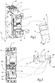
- the figure 1 illustrates in semi-perspective a complete fire protection system 1, comprising a starter-controller device 2 capable of being connected to an electrical installation via electrical conductors not shown in the figure.
- a spatial coordinate system (x, y, z) is represented on the figure 1 .
- the figure 2 illustrates the elements of the figure 1 along the y axis.
- Such a starter-controller device 2 has a function of protecting and controlling single-phase or three-phase motors, implementing in particular a function of protection against overcurrents (or circuit breaker function) and an isolation and power disconnection function.
- the electrical conductors are each suitable for being connected to the starter-controller device 2 at a respective connection terminal 6a, 6b, 6c.
- connection terminals are provided for the three-phase current phase electrical conductors.
- connection terminals between 2 and 4 More generally, a number of connection terminals between 2 and 4 is envisaged.
- the system 1 also comprises a fire protection device 10 able to be connected to the starter-controller device 2 and to protect this device 2 against a possible outbreak of fire due to a temperature rise above a predetermined threshold, denoted as threshold S.
- a fire protection device 10 able to be connected to the starter-controller device 2 and to protect this device 2 against a possible outbreak of fire due to a temperature rise above a predetermined threshold, denoted as threshold S.
- the fire protection device 10 is illustrated on the one hand as a separate module on the right-hand side of the figure 1 , and fitted in the front position in the starter-controller device 2.
- the protection device 10 comprises a housing 12, preferably of substantially parallelepiped shape, of small width l, substantially equal to the width of the starter-controller device 2, so as to fit it in a location provided in this device, and to low height H, of the order of 20mm.
- the protection device 10 comprises, on its front face 14 which will be positioned in front of the starter-controller device 2, a cartridge striker element 16, the operation of which in connection with a cartridge 17 containing fire extinguishing agent. , which is not visible on the figures 1 and 2 , will be described later.
- a light indicator 18, able to indicate the state of the fire protection device is also present on its front face 14.
- two injection elements 20a, 20b which are hollow, for example tubular, allow the injection of a fire extinguishing agent. to the electric power conductors of the starter-controller device.
- the injection elements 20a, 20b are located in spatial proximity to the cartridge 17 containing the extinguishing agent, allowing rapid release. of this extinguishing agent to the electric power conductors of the starter-controller device 2.
- the extinguishing agent used is for example a gas, for example CO 2 , or a foam.
- any type of fluid or gaseous fire extinguishing agent of electrical origin can be used.
- the protection device 10 is suitable for being embedded in the starter-controller device 2, and the elements 20a, 20b for injecting a fire extinguishing agent are intended to be positioned in the housings 22a, 22b of the starter-controller device 2.
- the protection device 10 also comprises on its rear face 14 'temperature sensors 24a, 24b, which are positioned, when the protection device 10 is embedded in the starter-controller device 2, in hollow locations 26a, 26b, at the bottom. level of electric power conductors.
- the temperature sensors 24a, 24b are located near the injection elements 20a, 20b, at the level of the electric power conductors, and include a portion projecting on the rear face 14 'of the protection device 10.
- the temperature sensors 24a, 24b are able to measure the temperature as close as possible to the electrical power conductors, so as to allow rapid tripping as soon as the temperature at the level of the electrical power conductors exceeds a predetermined threshold value and the injection elements 20a, 20b are able to inject the extinguishing agent directly at the level of the electric power conductors where the over-temperature has been detected.
- the temperature sensors 24a, 24b are electrically linked to the striker element 16, so as to allow its triggering and the release of the fire extinguishing agent, as soon as the temperature exceeds a predetermined temperature threshold S.
- the temperature threshold S is 110 ° C.
- the housing 12 of the protection device 10 comprises at least one mechanical link member 28 which is able to provide a mechanical link, via a link interface 30 of the starter-controller device 2, making it possible to control a lock mechanism allowing opening. and closing the electrical connection of the electrical power conductors in their respective connection terminals.
- the mechanical connecting element 28 is movable in the slot 31 of the starter-controller device, and is caused, according to an operation which will be described below, to be positioned in three distinct positions corresponding to ON, OFF and TRIP positions, respectively on, off and safety release.
- a change in the position of the mechanical connecting element 28, from a position corresponding to an electrical connection to a position corresponding to an electrical disconnection makes it possible to modify the position of the connection control member 32. / disconnection (on / off) of the starter-controller device 2.
- This mechanical connection element 28 is also an electrical connection control element.
- the protection device 10 makes it possible, via the mechanical connecting element 28, to maintain a locked disconnection position (TRIP position) following the detection of an outbreak of fire.
- the figure 3 illustrates in section a protection device 10 according to one embodiment of the invention.
- the protection device 10 comprises, in addition to the elements already described above, a locking spring 40 and a locking piston 42, a trigger element 44, a trigger spring 46 and a reset lever 48.
- the reset lever is accessible via a side wall of the housing 12, by a slot 49 pierced in this side wall.
- the cartridge striker 16 is triggered and pierces the cartridge 17, resulting in the release of the extinguishing agent. , to the injection elements 20a, 20b.
- the cartridge 17 is positioned substantially opposite the injection elements 20a, 20b, in great spatial proximity, preferably of the order of 15mm.
- the reactivity of the fire protection system implemented by the fire protection device 10 is very high.
- the extinguishing agent foam or gas, also fills the hollow spaces 50 of the protection device, which causes a displacement of the locking piston 42 along the z axis.
- the trigger element 44 is released and rotated along the z axis, under the action of the trigger spring 46.
- the movement of the trigger element 44 modifies the position of the mechanical link element 28, in translation along the x axis, and as well as the position of the reset lever 48.
- the protection device 10 further comprises a light pipe 51, the color of which is modified according to the position of the trigger element 44 and which indicates, by its end 18 visible on the front face 14 of the housing 12 of the protection device 10 the state of the safety device.
- the end 18 of the light pipe 51 forms a light indicator of the state of the protection device 10.
- the black color indicates normal operation and the red color a trip of the protection mechanism following the detection of a temperature above the temperature threshold.
- the figures 4 to 8 show in more detail the operation of the protection device 10.
- the figures 4 and 7 illustrate, in side view, the protection mechanism of the fire protection device according to two operating modes.
- the figures 5 and 6 are side views of the protection device 10, showing the slot 49 and the position of the corresponding reset lever 48.
- the figure 8 illustrates the starter controller device according to the xz plane, and the position of the link interface 30, receiving the mechanical link element 28, in the slot 31 according to the state before tripping (state Ei), after tripping (state Ef) the protective mechanism of the protective device 10.
- the figure 4 illustrates the operation of the protection device 10 when the sensed temperatures are below the temperature threshold, therefore the operating mode is normal.
- the locking piston 42 In the operating mode before tripping, the locking piston 42 is in a first rest position, and the locking spring 40 is compressed.
- the trigger element 44 is in the high position, held by the trigger spring 46.
- the connecting element is in position f.
- the reset lever 48 is in a first position P1, which is a low position, as illustrated in figure 5 .
- the locking piston 42 moves along the z axis, under the effect of the locking spring 40, actuated by the extinguishing agent released.
- the movement of the locking piston 42 causes the movement of the trigger element 44, which changes from position f or g to position h.
- the position of the mechanical interface 30 is modified by changing the position of the connecting element 28 for controlling the electrical connection of the fire prevention device, and the control device 32 (on / off) of the starter-controller device. 2 is locked in the OFF position (see figure 8 , operating state Ef), therefore in the position of disconnection of the electric power conductors.
- the light pipe 51 and the light indicator 18 indicate, by a change of color, a triggering of the security system.
- the protection device 10 thanks to the protection device 10, the power conductors are open and the reset is locked. A manual reset is possible afterwards.
- the protection device 10 can operate several times after resetting, and after changing the cartridge 17 containing an extinguishing agent, it is not limited to a single use.
- the fire protection device makes it possible to act for the rapid extinction of a possible outbreak of fire at the connection terminals or the electrical power conductors of a starter-controller device. an electrical installation, while ensuring an electrical disconnection and maintenance in the disconnected position.
Landscapes
- Health & Medical Sciences (AREA)
- Public Health (AREA)
- Business, Economics & Management (AREA)
- Emergency Management (AREA)
- Fire-Extinguishing By Fire Departments, And Fire-Extinguishing Equipment And Control Thereof (AREA)
- Thermally Actuated Switches (AREA)
Description
- La présente invention concerne un dispositif de protection anti-incendie d'un dispositif démarreur-contrôleur d'une installation électrique, le dispositif démarreur-contrôleur étant apte à être connectée à un conducteur de puissance électrique.
- Elle concerne également un système de protection anti-incendie associé.
- L'invention se situe dans le domaine de la protection contre les incendies dans les dispositifs de démarrage et de contrôle d'installations électriques.
- De tels dispositifs de démarrage et de contrôle d'installations électriques comprennent des conducteurs électriques de puissance dotés de conducteurs à contacts séparables. Les conducteurs électriques sont connectés au niveau de bornes de raccordement. Une des principales causes d'incendie connues est le desserrage des bornes de raccordement, qui provoque une montée en température dans le dispositif démarreur-contrôleur au niveau des bornes de raccordement, l'énergie emmagasinée suite à cette élévation de température pouvant provoquer un emballement thermique et un démarrage d'incendie. Un incendie provoqué localement se propage rapidement au niveau du tableau électrique de l'installation électrique, voire des bâtiments reliés électriquement par l'installation électrique.
- Il est connu de surveiller une montée en température au niveau de bornes de raccordement par des moyens de surveillance thermique.
- Le document
FR2979149 US 4,711,307 décrit aussi un dispositif de protection anti-incendie de l'état de l'art. - La présente invention a pour objectif de remédier à cet inconvénient, en proposant un dispositif de protection qui permet d'assurer une meilleure sécurité en cas de départ d'incendie.
- A cet effet, l'invention propose un dispositif de protection anti-incendie d'un dispositif démarreur-contrôleur d'une installation électrique selon la revendication 1.
- Avantageusement, le dispositif de l'invention comporte des capteurs de température aptes à détecter une température supérieure à un seuil prédéterminé, à proximité des conducteurs de puissance électrique du dispositif démarreur-contrôleur, et permet, grâce à l'agencement des divers éléments, une injection rapide d'un agent d'extinction vers lesdits conducteurs de puissance électrique.
- Ainsi, lorsqu'une température supérieure au seuil prédéterminé est détectée, un agent d'extinction d'incendie est libéré de manière à éteindre tout départ d'incendie et d'éviter la propagation de feu au niveau de l'installation électrique connectée.
- Le dispositif de protection selon l'invention peut également présenter une ou plusieurs des caractéristiques selon les revendications dépendantes 2 à 5.
- Selon un deuxième aspect, l'invention concerne un système de protection anti-incendie d'une installation électrique, comprenant un dispositif démarreur-contrôleur de l'installation électrique et un dispositif de protection anti-incendie tel que brièvement décrit ci-dessus, le dispositif de protection anti-incendie étant apte à être fixé en position frontale au dispositif démarreur-contrôleur.
- D'autres caractéristiques et avantages de l'invention ressortiront de la description qui en est donnée ci-dessous, à titre indicatif et nullement limitatif, en référence aux figures annexées, parmi lesquelles :
- la
figure 1 représente une vue éclatée en perspective d'un système de protection anti-incendie selon un mode de réalisation de l'invention ; - la
figure 2 représente une vue du système de protection de lafigure 1 , comprenant une vue du fond du dispositif de protection ; - la
figure 3 représente en détail un dispositif de protection anti-incendie selon un mode de réalisation de l'invention ; - la
figure 4 est une vue en coupe transversale du dispositif de protection anti-incendie dans un premier mode de fonctionnement ; - la
figure 5 est une vue de côté du dispositif de protection anti-incendie dans le premier mode de fonctionnement ; - la
figure 6 est une vue de côté du dispositif de protection anti-incendie dans un deuxième mode de fonctionnement ; - la
figure 7 est une vue en coupe transversale du dispositif de protection anti-incendie dans le deuxième de fonctionnement ; - la
figure 8 illustre le fonctionnement du dispositif démarreur-contrôleur sous l'action du dispositif de protection anti-incendie dans deux états différents. - Dans la description qui suit, les mêmes références indiquées sur différentes figures représentent les mêmes éléments.
- La
figure 1 illustre en semi-perspective un système complet de protection anti-incendie 1, comprenant un dispositif démarreur-contrôleur 2 apte à être connecté à une installation électrique via des conducteurs électriques non représentés sur la figure. - Un repère spatial (x,y,z) est représenté sur la
figure 1 . - La
figure 2 illustre les éléments de lafigure 1 selon l'axe y. - Un tel dispositif démarreur-contrôleur 2 a une fonction de protection et de commande de moteurs monophasés ou triphasés, implémentant notamment une fonction de protection contre les surintensités (ou fonction de disjonction) et une fonction d'isolement et de sectionnement de puissance.
- Les conducteurs électriques sont aptes chacun à être raccordé au dispositif démarreur-contrôleur 2 au niveau d'une borne de raccordement respective 6a, 6b, 6c.
- Dans l'exemple, trois bornes de raccordement sont prévues pour les conducteurs électriques de phase de courant triphasé.
- De manière plus générale, un nombre de bornes de raccordement compris entre 2 et 4 est envisagé.
- Le système 1 comprend également un dispositif de protection anti-incendie 10 apte à être raccordé au dispositif démarreur-contrôleur 2 et à protéger ce dispositif 2 contre un éventuel départ d'incendie dû à une élévation de température supérieure à un seuil prédéterminé, noté seuil S.
- Le dispositif de protection anti-incendie 10 est illustré d'une part en tant que module séparé sur la partie droite de la
figure 1 , et encastré en position frontale dans le dispositif démarreur-contrôleur 2. - Le dispositif de protection 10 comporte un boîtier 12, de préférence de forme sensiblement parallélépipédique, de faible largeur ℓ, sensiblement égale à la largeur du dispositif démarreur-contrôleur 2, de manière à l'encastrer à un emplacement prévu dans ce dispositif, et de faible hauteur H, de l'ordre de 20mm.
- Le dispositif de protection 10 comporte, sur sa face avant 14 qui sera positionnée à l'avant du dispositif démarreur-contrôleur 2, un élément 16 percuteur de cartouche, dont le fonctionnement en lien avec une cartouche 17 contenant agent d'extinction d'incendie, qui n'est pas visible sur les
figures 1 et 2 , sera décrit ultérieurement. - Un indicateur lumineux 18, apte à indiquer l'état du dispositif de protection anti-incendie est également présent sur sa face avant 14.
- Sur la face arrière 14' du dispositif de protection 10, opposée à la face avant 14, deux éléments d'injection 20a, 20b, qui sont creux, par exemple tubulaires, permettent l'injection d'un agent d'extinction d'incendie vers les conducteurs de puissance électrique du dispositif démarreur-contrôleur.
- Avantageusement, les éléments d'injection 20a, 20b sont situés à proximité spatiale de la cartouche 17 contenant l'agent d'extinction, permettant une libération rapide de cet agent d'extinction vers les conducteurs de puissance électrique du dispositif démarreur-contrôleur 2.
- L'agent d'extinction utilisé est par exemple un gaz, par exemple du CO2, ou une mousse. De manière générale, tout type d'agent fluide ou gazeux d'extinction d'incendie d'origine électrique est utilisable.
- Comme illustré sur les
figures 1 et 2 , le dispositif de protection 10 est apte à être encastré dans le dispositif démarreur-contrôleur 2, et les éléments 20a, 20b d'injection d'un agent d'extinction d'incendie sont destinés à se positionner dans des logements 22a, 22b du dispositif démarreur-contrôleur 2. - Le dispositif de protection 10 comporte également sur sa face arrière 14' des capteurs de température 24a, 24b, qui sont positionnés, lorsque le dispositif de protection 10 est encastré dans le dispositif démarreur-contrôleur 2, dans des emplacements creux 26a, 26b, au niveau des conducteurs de puissance électrique.
- Avantageusement, les capteurs de température 24a, 24b sont situés à proximité des éléments d'injection 20a, 20b, au niveau des conducteurs de puissance électrique, et comportent une portion en saillie sur la face arrière 14' du dispositif de protection 10.
- Ainsi, les capteurs de température 24a, 24b sont aptes à mesurer la température au plus près des conducteurs de puissance électrique, de manière à permettre un déclenchement rapide dès que la température au niveau des conducteurs de puissance électrique dépasse une valeur de seuil prédéterminée et les éléments d'injection 20a, 20b sont aptes à injecter l'agent d'extinction directement au niveau des conducteurs de puissance électrique où la sur-température a été détectée.
- Les capteurs de température 24a, 24b sont liés électriquement à l'élément percuteur 16, de manière à permettre son déclenchement et la libération de l'agent d'extinction d'incendie, dès que la température dépasse un seuil de température S prédéterminé.
- De préférence, le seuil de température S est de 110°C.
- Le boîtier 12 du dispositif de protection 10 comprend au moins un organe de liaison mécanique 28 qui est apte à réaliser une liaison mécanique, via une interface de liaison 30 du dispositif démarreur-contrôleur 2, permettant de contrôler un mécanisme de serrure permettant l'ouverture et la fermeture de la connexion électrique des conducteurs de puissance électrique dans leurs bornes de raccordement respectives.
- L'élément de liaison mécanique 28 est mobile dans la fente 31 du dispositif démarreur-contrôleur, et est amené, selon un fonctionnement qui sera décrit ci-après, à se positionner selon trois positions distinctes correspondant à des positions ON, OFF et TRIP, respectivement marche, arrêt et déclenchement de sécurité.
- Dans le système 1 proposé, un changement de position de l'élément de liaison mécanique 28, d'une position correspondant à une connexion électrique vers une position correspondant à une déconnexion électrique permet de modifier la position de l'organe de commande 32 de connexion/déconnexion (on/off) du dispositif démarreur-contrôleur 2.
- Ainsi, un changement de position de l'élément de liaison mécanique 28 permet de changer l'état de connexion électrique des conducteurs. Cet élément de liaison mécanique 28 est également un élément de contrôle de connexion électrique.
- De plus, le dispositif de protection 10 permet, via l'élément de liaison mécanique 28, de maintenir une position de déconnexion verrouillée (position TRIP) suite à la détection d'un départ d'incendie.
- La
figure 3 illustre en coupe un dispositif de protection 10 selon un mode de réalisation de l'invention. - Le dispositif de protection 10 comporte, outre les éléments déjà décrits ci-dessus, un ressort de verrouillage 40 et un piston de verrouillage 42, un élément déclencheur 44, un ressort déclencheur 46 ainsi qu'un levier de réarmement 48. Le levier de réarmement est accessible via une paroi latérale du boîtier 12, par une fente 49 percée dans cette paroi latérale.
- Lorsque les capteurs 24a, 24b détectent une élévation de la température au niveau des conducteurs de puissance supérieure au seuil de température prédéterminé, le percuteur de cartouche 16 se déclenche et perce la cartouche 17, ce qui entraîne la libération de l'agent d'extinction, vers les éléments d'injection 20a, 20b.
- Avantageusement, la cartouche 17 est positionnée sensiblement en regard des éléments d'injection 20a, 20b, à grande proximité spatiale, de préférence de l'ordre de 15mm.
- Ainsi, suite à la libération de l'agent d'extinction par percussion de la cartouche 17, cet agent d'extinction est quasi immédiatement acheminé au niveau des conducteurs de puissance électrique du dispositif démarreur-contrôleur 2.
- La réactivité du système de protection anti-incendie mise en place par le dispositif de protection anti-incendie 10 est très grande.
- L'agent d'extinction, mousse ou gaz, remplit également les espaces creux 50 du dispositif de protection, ce qui provoque un déplacement du piston de verrouillage 42 suivant l'axe z.
- Suite à ce déplacement, l'élément déclencheur 44 est libéré et entraîné en rotation selon l'axe z, sous l'action du ressort déclencheur 46.
- Le déplacement de l'élément déclencheur 44 modifie la position de l'élément de liaison mécanique 28, en translation selon l'axe x, et ainsi que la position du levier de réarmement 48.
- Le dispositif de protection 10 comprend en outre un conduit lumineux 51, dont la couleur est modifiée en fonction de la position de l'élément déclencheur 44 et qui indique, par son extrémité 18 visible sur la face avant 14 du boîtier 12 du dispositif de protection 10 l'état du dispositif de sécurité. Ainsi, l'extrémité 18 du conduit lumineux 51, forme un indicateur lumineux de l'état du dispositif de protection 10.
- Par exemple, la couleur noire indique un fonctionnement normal et la couleur rouge un déclenchement du mécanisme de protection suite à la détection d'une température supérieure au seuil de température.
- Les
figures 4 à 8 montrent plus en détail le fonctionnement du dispositif de protection 10. - Les
figures 4 et 7 illustrent, en vue de côté, le mécanisme de protection du dispositif de protection anti-incendie selon deux modes de fonctionnement. - Les
figures 5 et 6 sont des vues latérales du dispositif de protection 10, permettant de montrer la fente 49 et la position du levier de réarmement 48 correspondante. - La
figure 8 illustre le dispositif démarreur contrôleur selon le plan x-z, et la position de l'interface de liaison 30, réceptrice de l'élément de liaison mécanique 28, dans la fente 31 suivant l'état avant déclenchement (état Ei), après déclenchement (état Ef) du mécanisme de protection du dispositif de protection 10. - La
figure 4 illustre le fonctionnement du dispositif de protection 10 lorsque les températures captées sont inférieures au seuil de température, donc le mode de fonctionnement est normal. - Trois positions de l'élément de liaison 28, qui est l'extrémité de l'élément déclencheur 44, sont illustrées, notées f, g et h est correspondant respectivement aux positions ON, OFF et TRIP du mécanisme de serrure.
- En mode de fonctionnement avant déclenchement, le piston de verrouillage 42 est dans une première position de repos, et le ressort de verrouillage 40 est compressé. L'élément déclencheur 44 est en position haute, maintenu par le ressort déclencheur 46. L'élément de liaison est en position f.
- Le levier de réarmement 48 est dans une première position P1, qui est une position basse, comme illustré à la
figure 5 . - Lorsqu'une augmentation de température au-delà du seuil de température prédéterminé est détectée, le piston de verrouillage 42 se déplace suivant l'axe z, sous l'effet du ressort de verrouillage 40, actionné par l'agent d'extinction libéré.
- Le déplacement du piston de verrouillage 42 entraîne le déplacement de l'élément déclencheur 44, qui passe de position f ou g en position h.
- En parallèle, le levier de réarmement 48 passe en position P2, telle qu'illustrée à la
figure 6 . - La position de l'interface mécanique 30 est modifiée par le changement de position de l'élément de liaison 28 de contrôle de connexion électrique du dispositif anti-incendie, et l'organe de commande 32 (on/off) du dispositif démarreur-contrôleur 2 est verrouillé en position OFF (voir
figure 8 , état de fonctionnement Ef), donc en position de déconnexion des conducteurs de puissance électrique. - En parallèle, le conduit lumineux 51 et l'indicateur lumineux 18 indiquent, par un changement de couleur, un déclenchement du système de sécurité.
- Ainsi, grâce au dispositif de protection 10, les conducteurs puissance sont ouverts et le réarmement est verrouillé. Un réarmement manuel est possible par la suite.
- Avantageusement, le dispositif de protection 10 peut fonctionner à plusieurs reprises après réarmement, et après changement de la cartouche 17 contenant un agent d'extinction, il n'est pas limité à une seule utilisation.
- Avantageusement, le dispositif de protection anti-incendie selon l'invention permet d'agir pour l'extinction rapide d'un départ éventuel de feu au niveau des bornes de raccordement ou des conducteurs de puissance électrique d'un dispositif démarreur-contrôleur d'une installation électrique, tout en assurant une déconnexion électrique et un maintien en position déconnectée.
Claims (6)
- Dispositif de protection anti-incendie (10) d'un dispositif démarreur-contrôleur (2) d'une installation électrique, le dispositif démarreur-contrôleur (2) étant apte à être connecté à au moins un conducteur de puissance électrique, le dispositif de protection (10) comprenant des moyens de surveillance thermique du ou des conducteurs de puissance électrique aptes à détecter une élévation de température, supérieure à un seuil prédéterminé,caractérisé en ce qu'il est adapté à être fixé mécaniquement au dispositif démarreur-contrôleur (2) via au moins un organe de liaison mécanique (28,30),en ce que lesdits moyens de surveillance thermique comprennent au moins un capteur de température (24a, 24b), comportant une portion en saillie sur une face du dispositif de protection, apte à capter une température au niveau des conducteurs de puissance électrique du dispositif démarreur-contrôleur (2),et en ce qu'il comprend une cartouche (17) comprenant un agent d'extinction d'incendie et au moins un élément d'injection (20a, 20b), situé sur la même face du dispositif de protection que le ou les capteurs de température (24a, 24b), ladite cartouche étant située à l'intérieur du dispositif de protection (10), connectée auxdits capteurs de température (24a, 24b),l'élément d'injection (20a, 20b) étant apte à injecter l'agent d'extinction d'incendie vers les conducteurs de puissance électrique suite à une détection, par le capteur de température (24a, 24b), d'une température supérieure au seuil prédéterminé,le dispositif comportant en outre un piston de verrouillage (42), lié à un ressort de verrouillage (40), apte à être mis en mouvement lors de la libération de l'agent d'extinction d'incendie, et un élément déclencheur (44) apte à être déplacé selon un axe prédéterminé par déplacement du piston de verrouillage, et apte à entraîner un changement de position de l' élément de liaison mécanique (28,30) entre le dispositif de protection (10) et le dispositif démarreur contrôleur (2).
- Dispositif de protection anti-incendie (10) selon la revendication 1, caractérisé en ce que l'élément de liaison mécanique (28) est apte à prendre trois positions distinctes, comportant des positions de fonctionnement normal et une position de verrouillage, ladite position de verrouillage entraînant un verrouillage en position de déconnexion d'organe de commande (32) de connexion/déconnexion du dispositif démarreur-contrôleur (2).
- Dispositif de protection anti-incendie (10) selon l'une quelconque des revendications 1 ou 2, caractérisé en ce que ledit agent d'extinction d'incendie est un gaz ou une mousse.
- Dispositif de protection anti-incendie (10) selon l'une quelconque des revendications 1 à 3, caractérisé en ce que ledit seuil de température prédéterminé est de110°C.
- Dispositif de protection anti-incendie (10) selon l'une quelconque des revendications 1 à 4, caractérisé en ce que la cartouche (17) comprenant un agent d'extinction d'incendie est positionnée sensiblement en regard du ou des éléments d'injection (20a, 20b).
- Système de protection anti-incendie (1) d'une installation électrique, caractérisé en ce qu'il comprend un dispositif démarreur-contrôleur (2) de l'installation électrique et un dispositif de protection anti-incendie (10) conforme à l'une quelconque des revendications 1 à 5, le dispositif de protection anti-incendie (10) étant apte à être fixé en position frontale au dispositif démarreur-contrôleur.
Applications Claiming Priority (1)
| Application Number | Priority Date | Filing Date | Title |
|---|---|---|---|
| FR1459703A FR3026956B1 (fr) | 2014-10-09 | 2014-10-09 | Dispositif de protection anti-incendie d'un dispositif demarreur-controleur d'une installation electrique |
Publications (2)
| Publication Number | Publication Date |
|---|---|
| EP3006092A1 EP3006092A1 (fr) | 2016-04-13 |
| EP3006092B1 true EP3006092B1 (fr) | 2021-09-15 |
Family
ID=52130421
Family Applications (1)
| Application Number | Title | Priority Date | Filing Date |
|---|---|---|---|
| EP15189047.2A Not-in-force EP3006092B1 (fr) | 2014-10-09 | 2015-10-09 | Dispositif de protection anti-incendie d'un dispositif démarreur-contrôleur d'une installation électrique |
Country Status (3)
| Country | Link |
|---|---|
| US (1) | US10463897B2 (fr) |
| EP (1) | EP3006092B1 (fr) |
| FR (1) | FR3026956B1 (fr) |
Families Citing this family (5)
| Publication number | Priority date | Publication date | Assignee | Title |
|---|---|---|---|---|
| TWI666848B (zh) * | 2018-09-12 | 2019-07-21 | 財團法人工業技術研究院 | 蓄電系統消防裝置及其運作方法 |
| AU2020358475B2 (en) * | 2019-10-04 | 2026-04-30 | Tyco Fire Products Lp | Fire suppression systems including modular storage tanks |
| CN111969865B (zh) * | 2020-08-25 | 2021-12-03 | 深圳市珈玛纳米技术有限公司 | 一种具备防护机构的高频逆变电源 |
| EP4237100A4 (fr) | 2020-10-29 | 2024-08-14 | Tyco Fire Products LP | Système commandé et procédés de protection incendie de structure de stockage |
| CN114674072B (zh) * | 2020-12-25 | 2025-05-30 | 宁波奥克斯电气有限公司 | 电控盒组件及空调器 |
Family Cites Families (15)
| Publication number | Priority date | Publication date | Assignee | Title |
|---|---|---|---|---|
| GB2163954B (en) * | 1984-08-11 | 1987-12-02 | Fire Fighting Enterprises | Fire extinguisher |
| US4711307A (en) * | 1985-05-20 | 1987-12-08 | Harold Rosen | Compact self-contained fire extinguisher |
| US5808541A (en) * | 1995-04-04 | 1998-09-15 | Golden; Patrick E. | Hazard detection, warning, and response system |
| ATE206549T1 (de) * | 1997-03-11 | 2001-10-15 | Seeliger Hans Dieter | Schaltschrank mit feuerlöschsystem |
| US5936531A (en) * | 1998-03-06 | 1999-08-10 | Powers; Frank A. | Electrical fire sensing and prevention/extinguishing system |
| DE10311556A1 (de) * | 2003-02-18 | 2004-09-23 | Martin Reuter | Sicherheitsraum und Verfahren zur Kühlung eines Sicherheitsraumes |
| NL1026216C2 (nl) * | 2004-05-18 | 2005-11-21 | Fernandus Cornelis Koelewijn | Inrichting en werkwijze voor het tegen brand beveiligen van een object. |
| DE102005052777A1 (de) * | 2005-11-04 | 2007-05-24 | Amrona Ag | Vorrichtung zur Branderkennung in Schaltschränken |
| US20070169948A1 (en) * | 2006-01-26 | 2007-07-26 | C. Cretors And Company | Fire containment system |
| DE102006048015B4 (de) * | 2006-10-09 | 2015-01-29 | Minimax Gmbh & Co. Kg | Feuerlöschanlage für ein Gehäuse |
| NL2006769C2 (en) * | 2011-05-12 | 2012-11-13 | Fire Suppression Inside V O F | Method and system to avoid overheating of an electrical device. |
| FR2979149B1 (fr) | 2011-08-18 | 2014-05-30 | Cyril Charles | Dispositif de surveillance thermique des bornes d'un dispositif de connexion electrique |
| EP2755275B1 (fr) * | 2011-09-08 | 2017-06-07 | LG Chem, Ltd. | Appareil d'extinction d'incendie de bloc de batteries |
| US8817471B2 (en) * | 2011-11-16 | 2014-08-26 | Cooper Technologies Company | Overheat suppression systems and methods for an electrical housing |
| US20130264073A1 (en) * | 2012-04-10 | 2013-10-10 | Greg Ling | Integrated Thermal Event Suppression Apparatus |
-
2014
- 2014-10-09 FR FR1459703A patent/FR3026956B1/fr not_active Expired - Fee Related
-
2015
- 2015-09-30 US US14/870,348 patent/US10463897B2/en active Active
- 2015-10-09 EP EP15189047.2A patent/EP3006092B1/fr not_active Not-in-force
Also Published As
| Publication number | Publication date |
|---|---|
| EP3006092A1 (fr) | 2016-04-13 |
| US10463897B2 (en) | 2019-11-05 |
| FR3026956B1 (fr) | 2019-12-20 |
| US20160101305A1 (en) | 2016-04-14 |
| FR3026956A1 (fr) | 2016-04-15 |
Similar Documents
| Publication | Publication Date | Title |
|---|---|---|
| EP3006092A1 (fr) | Dispositif de protection anti-incendie d'un dispositif démarreur-contrôleur d'une installation électrique | |
| EP2232518B1 (fr) | Dispositif de protection contre les surtensions comportant un auxiliaire de deconnexion | |
| EP1607995B1 (fr) | Dispositif de protection contre des surtensions | |
| EP2879151B1 (fr) | Dispositif de protection anti-incendie d'un dispositif démarreur-contrôleur d'une installation électrique | |
| FR3101478A1 (fr) | Mecanismes de declenchement par levitation de contacts a utiliser avec des dispositifs de commutation incorporant des elements pyrotechniques | |
| EP3711077A1 (fr) | Dispositif de coupure pyrotechnique | |
| EP2745304B1 (fr) | Dispositif de surveillance thermique des bornes d'un dispositif de connexion électrique avec commutateur a la masse | |
| EP2602805B1 (fr) | Boîtier pour dispositif de protection contre les surtensions et dispositif de protection contre les surtensions associées | |
| FR3088592A1 (fr) | Dispositif de securite pour circuit-electrique de vehicule | |
| EP0441722B1 (fr) | Parafoudre déconnectable pour réseau à basse tension | |
| FR3112692A1 (fr) | Dispositif d’extinction de feu destiné à être monté sur le boîtier d’un appareil électrique, sur un équipement dans la cabine d’un aéronef ou dans une cavité dans la structure d’un aéronef | |
| FR2974684A1 (fr) | Systeme de protection et de supervision d'un circuit de distribution d'energie electrique a courant continu | |
| EP0901142B1 (fr) | Dispositif de signalisation d'un défaut électrique dans un dispositif de coupure tel un interrupteur différentiel | |
| FR2942920A1 (fr) | Boitier comprenant un ou plusieurs composants electriques | |
| EP1544884B1 (fr) | Disjoncteur embarqué avec mécanisme d'autorisation de réarmement | |
| FR2857630A1 (fr) | Vehicule automobile muni d'un reservoir de gaz, a securite renforcee | |
| EP3297111B1 (fr) | Dispositif et procede de surveillance de l'activite d'unites de traitement dans un declencheur electrique | |
| FR3136626A1 (fr) | Dispositif passif pour la protection d’une boîte de jonction électrique d’une alimentation électrique basse tension d’un bâtiment contre une température élevée indésirable ou des combustions à flamme | |
| FR3085225A1 (fr) | Mécanismes de déclenchement passifs destinés à être utilisés avec des dispositifs de commutation intégrant des éléments pyrotechniques | |
| FR2857632A1 (fr) | Vehicule automobile avec reservoir de combustible gazeux et circuit d'alimentation basse pression | |
| FR3028661A1 (fr) | Disjoncteur electrique incluant un bloc declencheur | |
| EP2449570B1 (fr) | Module de protection contre les surtensions et ensemble de protection comportant un tel module | |
| FR3132388A1 (fr) | Système d’alimentation électrique embarqué | |
| EP4075471A1 (fr) | Module auxiliaire de protection électrique, appareil de protection électrique comportant un tel module, et procédé de fonctionnement associé | |
| EP1213740A1 (fr) | Dispositif de réarmement automatique pour appareillage modulaire de protection à commander |
Legal Events
| Date | Code | Title | Description |
|---|---|---|---|
| PUAI | Public reference made under article 153(3) epc to a published international application that has entered the european phase |
Free format text: ORIGINAL CODE: 0009012 |
|
| AK | Designated contracting states |
Kind code of ref document: A1 Designated state(s): AL AT BE BG CH CY CZ DE DK EE ES FI FR GB GR HR HU IE IS IT LI LT LU LV MC MK MT NL NO PL PT RO RS SE SI SK SM TR |
|
| AX | Request for extension of the european patent |
Extension state: BA ME |
|
| 17P | Request for examination filed |
Effective date: 20160923 |
|
| RBV | Designated contracting states (corrected) |
Designated state(s): AL AT BE BG CH CY CZ DE DK EE ES FI FR GB GR HR HU IE IS IT LI LT LU LV MC MK MT NL NO PL PT RO RS SE SI SK SM TR |
|
| GRAP | Despatch of communication of intention to grant a patent |
Free format text: ORIGINAL CODE: EPIDOSNIGR1 |
|
| STAA | Information on the status of an ep patent application or granted ep patent |
Free format text: STATUS: GRANT OF PATENT IS INTENDED |
|
| RIC1 | Information provided on ipc code assigned before grant |
Ipc: H01H 71/02 20060101ALN20210415BHEP Ipc: H01H 89/06 20060101ALN20210415BHEP Ipc: A62C 3/16 20060101AFI20210415BHEP |
|
| INTG | Intention to grant announced |
Effective date: 20210514 |
|
| GRAS | Grant fee paid |
Free format text: ORIGINAL CODE: EPIDOSNIGR3 |
|
| GRAA | (expected) grant |
Free format text: ORIGINAL CODE: 0009210 |
|
| STAA | Information on the status of an ep patent application or granted ep patent |
Free format text: STATUS: THE PATENT HAS BEEN GRANTED |
|
| AK | Designated contracting states |
Kind code of ref document: B1 Designated state(s): AL AT BE BG CH CY CZ DE DK EE ES FI FR GB GR HR HU IE IS IT LI LT LU LV MC MK MT NL NO PL PT RO RS SE SI SK SM TR |
|
| REG | Reference to a national code |
Ref country code: GB Ref legal event code: FG4D Free format text: NOT ENGLISH Ref country code: CH Ref legal event code: EP |
|
| REG | Reference to a national code |
Ref country code: DE Ref legal event code: R096 Ref document number: 602015073259 Country of ref document: DE |
|
| REG | Reference to a national code |
Ref country code: IE Ref legal event code: FG4D Free format text: LANGUAGE OF EP DOCUMENT: FRENCH |
|
| REG | Reference to a national code |
Ref country code: AT Ref legal event code: REF Ref document number: 1430079 Country of ref document: AT Kind code of ref document: T Effective date: 20211015 |
|
| REG | Reference to a national code |
Ref country code: LT Ref legal event code: MG9D |
|
| REG | Reference to a national code |
Ref country code: NL Ref legal event code: MP Effective date: 20210915 |
|
| PG25 | Lapsed in a contracting state [announced via postgrant information from national office to epo] |
Ref country code: HR Free format text: LAPSE BECAUSE OF FAILURE TO SUBMIT A TRANSLATION OF THE DESCRIPTION OR TO PAY THE FEE WITHIN THE PRESCRIBED TIME-LIMIT Effective date: 20210915 Ref country code: SE Free format text: LAPSE BECAUSE OF FAILURE TO SUBMIT A TRANSLATION OF THE DESCRIPTION OR TO PAY THE FEE WITHIN THE PRESCRIBED TIME-LIMIT Effective date: 20210915 Ref country code: RS Free format text: LAPSE BECAUSE OF FAILURE TO SUBMIT A TRANSLATION OF THE DESCRIPTION OR TO PAY THE FEE WITHIN THE PRESCRIBED TIME-LIMIT Effective date: 20210915 Ref country code: LT Free format text: LAPSE BECAUSE OF FAILURE TO SUBMIT A TRANSLATION OF THE DESCRIPTION OR TO PAY THE FEE WITHIN THE PRESCRIBED TIME-LIMIT Effective date: 20210915 Ref country code: BG Free format text: LAPSE BECAUSE OF FAILURE TO SUBMIT A TRANSLATION OF THE DESCRIPTION OR TO PAY THE FEE WITHIN THE PRESCRIBED TIME-LIMIT Effective date: 20211215 Ref country code: NO Free format text: LAPSE BECAUSE OF FAILURE TO SUBMIT A TRANSLATION OF THE DESCRIPTION OR TO PAY THE FEE WITHIN THE PRESCRIBED TIME-LIMIT Effective date: 20211215 Ref country code: FI Free format text: LAPSE BECAUSE OF FAILURE TO SUBMIT A TRANSLATION OF THE DESCRIPTION OR TO PAY THE FEE WITHIN THE PRESCRIBED TIME-LIMIT Effective date: 20210915 |
|
| REG | Reference to a national code |
Ref country code: AT Ref legal event code: MK05 Ref document number: 1430079 Country of ref document: AT Kind code of ref document: T Effective date: 20210915 |
|
| PG25 | Lapsed in a contracting state [announced via postgrant information from national office to epo] |
Ref country code: LV Free format text: LAPSE BECAUSE OF FAILURE TO SUBMIT A TRANSLATION OF THE DESCRIPTION OR TO PAY THE FEE WITHIN THE PRESCRIBED TIME-LIMIT Effective date: 20210915 Ref country code: GR Free format text: LAPSE BECAUSE OF FAILURE TO SUBMIT A TRANSLATION OF THE DESCRIPTION OR TO PAY THE FEE WITHIN THE PRESCRIBED TIME-LIMIT Effective date: 20211216 |
|
| PG25 | Lapsed in a contracting state [announced via postgrant information from national office to epo] |
Ref country code: AT Free format text: LAPSE BECAUSE OF FAILURE TO SUBMIT A TRANSLATION OF THE DESCRIPTION OR TO PAY THE FEE WITHIN THE PRESCRIBED TIME-LIMIT Effective date: 20210915 |
|
| REG | Reference to a national code |
Ref country code: CH Ref legal event code: PL |
|
| PG25 | Lapsed in a contracting state [announced via postgrant information from national office to epo] |
Ref country code: IS Free format text: LAPSE BECAUSE OF FAILURE TO SUBMIT A TRANSLATION OF THE DESCRIPTION OR TO PAY THE FEE WITHIN THE PRESCRIBED TIME-LIMIT Effective date: 20220115 Ref country code: SM Free format text: LAPSE BECAUSE OF FAILURE TO SUBMIT A TRANSLATION OF THE DESCRIPTION OR TO PAY THE FEE WITHIN THE PRESCRIBED TIME-LIMIT Effective date: 20210915 Ref country code: SK Free format text: LAPSE BECAUSE OF FAILURE TO SUBMIT A TRANSLATION OF THE DESCRIPTION OR TO PAY THE FEE WITHIN THE PRESCRIBED TIME-LIMIT Effective date: 20210915 Ref country code: RO Free format text: LAPSE BECAUSE OF FAILURE TO SUBMIT A TRANSLATION OF THE DESCRIPTION OR TO PAY THE FEE WITHIN THE PRESCRIBED TIME-LIMIT Effective date: 20210915 Ref country code: PT Free format text: LAPSE BECAUSE OF FAILURE TO SUBMIT A TRANSLATION OF THE DESCRIPTION OR TO PAY THE FEE WITHIN THE PRESCRIBED TIME-LIMIT Effective date: 20220117 Ref country code: PL Free format text: LAPSE BECAUSE OF FAILURE TO SUBMIT A TRANSLATION OF THE DESCRIPTION OR TO PAY THE FEE WITHIN THE PRESCRIBED TIME-LIMIT Effective date: 20210915 Ref country code: NL Free format text: LAPSE BECAUSE OF FAILURE TO SUBMIT A TRANSLATION OF THE DESCRIPTION OR TO PAY THE FEE WITHIN THE PRESCRIBED TIME-LIMIT Effective date: 20210915 Ref country code: ES Free format text: LAPSE BECAUSE OF FAILURE TO SUBMIT A TRANSLATION OF THE DESCRIPTION OR TO PAY THE FEE WITHIN THE PRESCRIBED TIME-LIMIT Effective date: 20210915 Ref country code: EE Free format text: LAPSE BECAUSE OF FAILURE TO SUBMIT A TRANSLATION OF THE DESCRIPTION OR TO PAY THE FEE WITHIN THE PRESCRIBED TIME-LIMIT Effective date: 20210915 Ref country code: CZ Free format text: LAPSE BECAUSE OF FAILURE TO SUBMIT A TRANSLATION OF THE DESCRIPTION OR TO PAY THE FEE WITHIN THE PRESCRIBED TIME-LIMIT Effective date: 20210915 Ref country code: AL Free format text: LAPSE BECAUSE OF FAILURE TO SUBMIT A TRANSLATION OF THE DESCRIPTION OR TO PAY THE FEE WITHIN THE PRESCRIBED TIME-LIMIT Effective date: 20210915 |
|
| REG | Reference to a national code |
Ref country code: DE Ref legal event code: R097 Ref document number: 602015073259 Country of ref document: DE |
|
| REG | Reference to a national code |
Ref country code: BE Ref legal event code: MM Effective date: 20211031 |
|
| PG25 | Lapsed in a contracting state [announced via postgrant information from national office to epo] |
Ref country code: MC Free format text: LAPSE BECAUSE OF FAILURE TO SUBMIT A TRANSLATION OF THE DESCRIPTION OR TO PAY THE FEE WITHIN THE PRESCRIBED TIME-LIMIT Effective date: 20210915 |
|
| PLBE | No opposition filed within time limit |
Free format text: ORIGINAL CODE: 0009261 |
|
| STAA | Information on the status of an ep patent application or granted ep patent |
Free format text: STATUS: NO OPPOSITION FILED WITHIN TIME LIMIT |
|
| PG25 | Lapsed in a contracting state [announced via postgrant information from national office to epo] |
Ref country code: LU Free format text: LAPSE BECAUSE OF NON-PAYMENT OF DUE FEES Effective date: 20211009 Ref country code: DK Free format text: LAPSE BECAUSE OF FAILURE TO SUBMIT A TRANSLATION OF THE DESCRIPTION OR TO PAY THE FEE WITHIN THE PRESCRIBED TIME-LIMIT Effective date: 20210915 Ref country code: BE Free format text: LAPSE BECAUSE OF NON-PAYMENT OF DUE FEES Effective date: 20211031 |
|
| 26N | No opposition filed |
Effective date: 20220616 |
|
| GBPC | Gb: european patent ceased through non-payment of renewal fee |
Effective date: 20211215 |
|
| PG25 | Lapsed in a contracting state [announced via postgrant information from national office to epo] |
Ref country code: SI Free format text: LAPSE BECAUSE OF FAILURE TO SUBMIT A TRANSLATION OF THE DESCRIPTION OR TO PAY THE FEE WITHIN THE PRESCRIBED TIME-LIMIT Effective date: 20210915 Ref country code: LI Free format text: LAPSE BECAUSE OF NON-PAYMENT OF DUE FEES Effective date: 20211031 Ref country code: CH Free format text: LAPSE BECAUSE OF NON-PAYMENT OF DUE FEES Effective date: 20211031 |
|
| PG25 | Lapsed in a contracting state [announced via postgrant information from national office to epo] |
Ref country code: IE Free format text: LAPSE BECAUSE OF NON-PAYMENT OF DUE FEES Effective date: 20211009 Ref country code: GB Free format text: LAPSE BECAUSE OF NON-PAYMENT OF DUE FEES Effective date: 20211215 |
|
| PG25 | Lapsed in a contracting state [announced via postgrant information from national office to epo] |
Ref country code: IT Free format text: LAPSE BECAUSE OF FAILURE TO SUBMIT A TRANSLATION OF THE DESCRIPTION OR TO PAY THE FEE WITHIN THE PRESCRIBED TIME-LIMIT Effective date: 20210915 |
|
| PG25 | Lapsed in a contracting state [announced via postgrant information from national office to epo] |
Ref country code: HU Free format text: LAPSE BECAUSE OF FAILURE TO SUBMIT A TRANSLATION OF THE DESCRIPTION OR TO PAY THE FEE WITHIN THE PRESCRIBED TIME-LIMIT; INVALID AB INITIO Effective date: 20151009 |
|
| PG25 | Lapsed in a contracting state [announced via postgrant information from national office to epo] |
Ref country code: CY Free format text: LAPSE BECAUSE OF FAILURE TO SUBMIT A TRANSLATION OF THE DESCRIPTION OR TO PAY THE FEE WITHIN THE PRESCRIBED TIME-LIMIT Effective date: 20210915 |
|
| PG25 | Lapsed in a contracting state [announced via postgrant information from national office to epo] |
Ref country code: MK Free format text: LAPSE BECAUSE OF FAILURE TO SUBMIT A TRANSLATION OF THE DESCRIPTION OR TO PAY THE FEE WITHIN THE PRESCRIBED TIME-LIMIT Effective date: 20210915 |
|
| PG25 | Lapsed in a contracting state [announced via postgrant information from national office to epo] |
Ref country code: MT Free format text: LAPSE BECAUSE OF FAILURE TO SUBMIT A TRANSLATION OF THE DESCRIPTION OR TO PAY THE FEE WITHIN THE PRESCRIBED TIME-LIMIT Effective date: 20210915 |
|
| PGFP | Annual fee paid to national office [announced via postgrant information from national office to epo] |
Ref country code: DE Payment date: 20241029 Year of fee payment: 10 |
|
| PGFP | Annual fee paid to national office [announced via postgrant information from national office to epo] |
Ref country code: FR Payment date: 20241025 Year of fee payment: 10 |
|
| PG25 | Lapsed in a contracting state [announced via postgrant information from national office to epo] |
Ref country code: TR Free format text: LAPSE BECAUSE OF FAILURE TO SUBMIT A TRANSLATION OF THE DESCRIPTION OR TO PAY THE FEE WITHIN THE PRESCRIBED TIME-LIMIT Effective date: 20210915 |
|
| REG | Reference to a national code |
Ref country code: DE Ref legal event code: R119 Ref document number: 602015073259 Country of ref document: DE |
|
| PG25 | Lapsed in a contracting state [announced via postgrant information from national office to epo] |
Ref country code: DE Free format text: LAPSE BECAUSE OF NON-PAYMENT OF DUE FEES Effective date: 20260501 |
|
| PG25 | Lapsed in a contracting state [announced via postgrant information from national office to epo] |
Ref country code: FR Free format text: LAPSE BECAUSE OF NON-PAYMENT OF DUE FEES Effective date: 20251031 |