EP3005972A1 - Hand piece for spraying powder - Google Patents
Hand piece for spraying powder Download PDFInfo
- Publication number
- EP3005972A1 EP3005972A1 EP14807381.0A EP14807381A EP3005972A1 EP 3005972 A1 EP3005972 A1 EP 3005972A1 EP 14807381 A EP14807381 A EP 14807381A EP 3005972 A1 EP3005972 A1 EP 3005972A1
- Authority
- EP
- European Patent Office
- Prior art keywords
- powder
- pellet
- hand piece
- spraying
- grinder
- Prior art date
- Legal status (The legal status is an assumption and is not a legal conclusion. Google has not performed a legal analysis and makes no representation as to the accuracy of the status listed.)
- Granted
Links
Images



Classifications
-
- A—HUMAN NECESSITIES
- A61—MEDICAL OR VETERINARY SCIENCE; HYGIENE
- A61C—DENTISTRY; APPARATUS OR METHODS FOR ORAL OR DENTAL HYGIENE
- A61C3/00—Dental tools or instruments
- A61C3/02—Tooth drilling or cutting instruments; Instruments acting like a sandblast machine
- A61C3/025—Instruments acting like a sandblast machine, e.g. for cleaning, polishing or cutting teeth
-
- A—HUMAN NECESSITIES
- A61—MEDICAL OR VETERINARY SCIENCE; HYGIENE
- A61C—DENTISTRY; APPARATUS OR METHODS FOR ORAL OR DENTAL HYGIENE
- A61C5/00—Filling or capping teeth
- A61C5/50—Implements for filling root canals; Methods or instruments for medication of tooth nerve channels
-
- A—HUMAN NECESSITIES
- A61—MEDICAL OR VETERINARY SCIENCE; HYGIENE
- A61C—DENTISTRY; APPARATUS OR METHODS FOR ORAL OR DENTAL HYGIENE
- A61C1/00—Dental machines for boring or cutting ; General features of dental machines or apparatus, e.g. hand-piece design
- A61C1/08—Machine parts specially adapted for dentistry
- A61C1/087—Supplying powder or medicines
Definitions
- the present invention mainly relates to a hand piece used for spraying powder in dental treatment.
- Patent Literature 1 Japanese Patent Publication No. 2001-293009
- the present invention provides a small and portable hand piece for spraying powder inside which a pellet is ground to generate the powder.
- the present invention provides the hand piece for spraying powder as follows.
- a hand piece for spraying powder including a pellet storage part for storing a pellet, a powder generation part for generating powder by grinding the stored pellet, and a spray port for spraying the powder generated in the powder generation part is provided.
- the hand piece for spraying powder wherein the powder generation part includes an elastic body for urging the pellet in the pellet storage part, a grinder abutting on the pellet urged by the elastic body, and a vibrator for vibrating the grinder, is provided.
- the hand piece for spraying powder wherein the powder generation part includes the elastic body for urging the pellet in the pellet storage part, the grinder abutting on the pellet urged by the elastic body, and a rotator for rotating the grinder, is provided.
- the hand piece for spraying powder wherein the powder generation part includes a linear motion actuator for urging the pellet in the pellet storage part, a grinder abutting on the pellet urged by the linear motion actuator, and the vibrator for vibrating the grinder, is provided.
- the hand piece for spraying powder wherein the powder generation part includes the linear motion actuator for urging the pellet in the pellet storage part, the grinder abutting on the pellet urged by the linear motion actuator, and the rotator for rotating the grinder, is provided.
- the hand piece for spraying powder additionally having an acceleration gas pipe which acceleration gas passes through and a powder lead-out pipe for spraying powder by utilizing negative pressure generated by the acceleration gas passing through the acceleration gas pipe via which the powder generation part leads to the spray port, is provided.
- the hand piece for spraying powder wherein the pellet is obtained by compacting hydroxyapatite powder and wherein the spray port is for spraying the hydroxyapatite powder toward a human tooth, is provided.
- the hand piece for spraying powder having a compressed gas cylinder for generating the acceleration gas and a power supply part for supplying the compressed gas cylinder and the powder generation part with power, is provided.
- the hand piece for spraying powder having a gas pump for generating the acceleration gas and a power supply part for supplying the gas pump and the powder generation part with power, is provided.
- a small and portable hand piece for spraying powder inside which a pellet is ground to generate the powder can be provided.
- Embodiments of the present invention will be described below by using the attached drawings. The present invention is not limited to these embodiments and can be put into practice in various modes within a range not departing from its gist.
- An embodiment 1 will be described mainly for claim 1.
- An embodiment 2 will be described mainly for claims 2 and 4.
- An embodiment 3 will be described mainly for claims 3 and 5.
- An embodiment 4 will be described mainly for claim 6.
- An embodiment 5 will be described mainly for claim 7.
- An embodiment 6 will be described mainly for claims 8 and 9.
- the hand piece for spraying powder of this embodiment is characterized in that powder generated by grinding a pellet inside the hand piece is sprayed from a spray port.
- the hand piece for spraying powder of this embodiment includes a pellet storage part, a powder generation part, and a spray port.
- Fig. 1 is a schematic view illustrating the structure of the hand piece for spraying powder of this embodiment.
- the "pellet storage part” (0101) is a part for storing a pellet (0102) which provides powder, having a function for fixing and keeping the pellet inside the hand piece.
- the pellet may be a compression body obtained by compressing powder, or a bulk body which is not made from powder. In the case where the pellet is a compression body, it has an advantage of being easier to grind than in the case where the pellet is a bulk body.
- hydroxyapatite white ceramics powder, colored ceramics powder, organic components, metal powder and the like
- white ceramics include titanium oxide, aluminum oxide, zirconium oxide, silicon dioxide and the like.
- colored ceramics powder include bismuth oxide and the like.
- organic components include polyacrylic acid methyl powder, a polystyrene sphere, a nylon sphere and the like.
- the pellet storage part only needs to have enough capacity to store the pellet. Therefore, in the hand piece for spraying powder of this embodiment, unlike in the conventional technology where powder which has been powdered in advance is stored, powder can be sprayed even with a hand piece which does not have a powder storage part of enough capacity.
- the "powder generation part” (0103) is a part which is arranged closely to the pellet storage part, having a function for generating powder from the pellet.
- a configuration where a grindstone-shaped part grinds the pellet a configuration where a brush powders the pellet by vibration, a configuration where a net-shaped part generates powder by grinding the pellet, a configuration where a propeller-shaped part powders the pellet by rotation and the like can be considered.
- the "spray port” (0104) is a part which is connected to the powder generation part, having a function for spraying powder generated in the powder generation part.
- the shape of the spray port is not limited but preferably circular in manufacturing. It may also be oval so that a spray area can be wide.
- the hand piece for spraying powder of this embodiment in addition to the above essential components, has an actuator for generating powder (0105) for actuating the powder generation part and a power source (0106) of the actuator for generating powder.
- the actuator for generating powder actuates the powder generation part utilizing energy supplied from the power source. Then, powder is generated from the pellet by action of the powder generation part.
- the hand piece for spraying powder of this embodiment in addition to the above essential components, has a compressed gas cylinder or a gas pump (0107) which supplies gas for making powder flow and a powder flow passage (0108) via which the powder generation part leads to the spray port. Powder generated in the powder generation part is carried to the powder flow passage by a flow of gas supplied from the compressed gas cylinder or the gas pump (which is called supplied gas) passes through the powder flow passage, and is sprayed from the spray port.
- supplied gas supplied from the compressed gas cylinder or the gas pump
- Various kinds of gas such as air generated by the gas pump, air sealed in the compressed gas cylinder, nitrogen gas, helium gas and the like can be used.
- the hand piece for spraying powder of this embodiment can be used toward not only a human tooth but also various objects such as an implant body, bone, glass, a nail, an artificial joint and the like.
- the hand piece for spraying powder of this embodiment can also be used for wiring on printed boards, spraying conductors and metal powder and the like.
- each of the above components is not limited in size and can be formed in any size.
- a small and portable hand piece for spraying powder inside which a pellet is ground to generate the powder can be provided.
- the hand piece for spraying powder of this embodiment is characterized by being so configured that the powder generation part grinds the pellet urged by an elastic body by vibration of a grinder abutting on the pellet.
- the hand piece for spraying powder in which urging the pellet is performed by a linear motion actuator instead of the elastic body will also be described.
- the hand piece for spraying powder of this embodiment includes the pellet storage part, the powder generation part, and the spray port. Since the pellet storage part and the spray port are the same as described in the embodiment 1, the description thereof is omitted.
- the powder generation part in this embodiment includes an elastic body, a grinder, and a vibrator. Refer to Fig. 2.
- Fig. 2 is a schematic view illustrating the structure of the powder generation part in the hand piece for spraying powder of this embodiment.
- the “elastic body” (0209) is a part with elasticity, having a function for urging the pellet stored in the pellet storage part.
- Examples of the elastic body in this embodiment include a spring. As the pellet is urged by the elastic body, it is strongly pressed onto the grinder which will be described in detail, thereby grinding efficiency is improved.
- the linear motion actuator is a machine element which converts input energy into linear motion.
- the linear motion means linear expanding and contracting motion or linear bending and stretching motion.
- Examples of the linear motion actuator include an air cylinder, an electric cylinder and the like.
- the air cylinder is a machine element which makes a piston move linearly by compressed air. This air cylinder urges the pellet by imparting pressure.
- the electric cylinder converts rotary motion of an electric motor into linear motion of a piston and the like.
- a hydraulic cylinder can also be used.
- the arrangement position of these linear motion actuators is the same as that of the elastic body. They may be arranged at a position where they can urge the pellet so that it abuts on the grinder.
- a kind of the linear motion actuator is not particularly limited, but it is preferable to be a small one.
- the "grinder” (0210) is a part abutting on the pellet, having a function for grinding the pellet to generate powder.
- a grindstone, a brush, a net, a cutting blade and the like can be considered.
- the "vibrator” (0211) is a part interlocking with the grinder, having a function for vibrating the grinder.
- the vibrator include an ultrasonic vibrator.
- the grinder vibrates in interlock with the ultrasonic vibrator and the pellet is ground by vibration of the grinder.
- the vibrator may also be embodied by a motor.
- the motor can vibrate the grinder with an action the amplitude of which is larger than in the case where the ultrasonic vibrator is used.
- Whether to use the ultrasonic vibrator or the motor as the vibrator may be suitably determined according to material, structure, and composition of the pellet to be ground and the desired diameter (particle size) of powder.
- Fig. 3 (a) is a schematic view illustrating a mode where the motor makes the grinder reciprocate (move longitudinally). As illustrated, the grinder (0301) is reciprocated (moved longitudinally) by the motor (0302), thereby the pellet (0303) urged to the grinder is ground.
- Fig. 3(b) is a schematic view illustrating a mode where the grinder is moved vertically by the motor. As illustrated, the grinder (0301) is moved vertically by the motor (0302), thereby the pellet (0303) urged to the grinder is ground.
- the positional relationship between the elastic body or the linear motion actuator for urging the pellet and the grinder is not limited to such a relationship that the grinder is arranged at the spray port side and the elastic body is arranged to face the grinder across the pellet, as illustrated in Fig. 2 . That is to say, it may also be so configured that the elastic body or the linear motion actuator is arranged at the spray port side and the grinder is arranged to face the elastic body or the linear motion actuator across the pellet.
- the arrangement of the elastic body or the linear motion actuator and the grinder can be suitably determined according to the position of the pellet storage part and a storage opening for storing the pellet in the pellet storage part. It is desirable to determine the arrangement of each part considering ease of storing the pellet and the like.
- the particle size of the generated powder can be changed by controlling a frequency, a cutting amount, and a feeding amount.
- the generation amount of the powder per unit time can also be changed by controlling a frequency or duty ratio.
- a small and portable hand piece for spraying powder inside which a pellet is ground to generate the powder can be provided.
- the hand piece for spraying powder of this embodiment is characterized in that it is so configured that the powder generation part grinds the pellet urged by the elastic body by rotation of the grinder abutting on the pellet.
- the hand piece for spraying powder of this embodiment includes the pellet storage part, the powder generation part, and the spray port. Since the pellet storage part and the spray port are the same as described in the embodiment 1, the description thereof is omitted.
- the powder generation part is the same as described in the embodiment 2, except for the following points.
- the "powder generation part" of the hand piece for spraying powder of this embodiment includes the elastic body, the grinder, and a rotator.
- the "rotator” is a part interlocking with the grinder, having a function for rotating the grinder.
- the motor can be used to embody the rotator, for example.
- Figs. 4 are schematic views illustrating a mode where the grinder is rotated by the motor.
- Fig. 4 (a) is a mode where the grinder is rotated in one direction continuously. As illustrated, the grinder (0401) is rotated in one direction by the motor (0402), thereby the urged pellet (0403) is ground.
- Fig. 4(b) is a schematic view illustrating a mode where the grinder alternately repeats clockwise rotation and counterclockwise rotation. As illustrated, the grinder (0401) alternately repeats clockwise rotation and counterclockwise rotation by action of the motor (0402), thereby the urged pellet (0403) is ground.
- a small and portable hand piece for spraying powder inside which a pellet is ground to generate the powder can be provided.
- the hand piece for spraying powder of this embodiment is characterized by spraying powder utilizing negative pressure generated by acceleration gas.
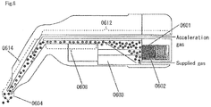
- the hand piece for spraying powder of this embodiment includes the pellet storage part, the powder generation part, and the spray port, having an acceleration gas pipe and a powder lead-out pipe in addition. Since the pellet storage part, the powder generation part, and the spray port are the same as described in the embodiment 1, the description thereof is omitted. Refer to Fig. 5.
- Fig. 5 is a schematic view illustrating the structure of the hand piece for spraying powder of this embodiment.
- the “acceleration gas pipe” (0512) is a part which acceleration gas passes through.
- the acceleration gas is gas supplied from an acceleration gas intake port (0513), having a function for accelerating powder toward the direction of the spray port.
- the “powder lead-out pipe” (0514) is a part connected to the spray port, having a function for carrying powder to the spray port.
- various kinds of gas such as nitrogen gas, helium gas and the like can be used as the acceleration gas.
- a gas pump and a compressed gas cylinder filled with various kinds of gas can be used to supply the acceleration gas, for example.
- the hand piece for spraying powder of this embodiment in addition to the above essential components, has an actuator for generating powder for actuating the powder generation part, a power source of the actuator for generating powder, a powder flow passage, and supplied gas (0515).
- Fig. 6 is a schematic view illustrating a flow of powder and air in the hand piece for spraying powder of this embodiment.
- the acceleration gas supplied from the acceleration gas intake port flows into the powder lead-out pipe. Since the powder lead-out pipe is joined with the powder flow passage, air inside the powder flow passage is pulled by the acceleration gas and negative pressure is generated in the powder flow passage and the powder generation part. Then, the powder generated in the powder generation part moves in the direction of the powder lead-out pipe, passes through the powder lead-out pipe, and is sprayed from the spray port. In this way, since powder is carried by negative pressure, an effect of powder being hard to adhere to a pipe wall can be obtained.
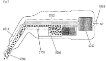
- Fig. 7 is a schematic view illustrating another mode of the hand piece for spraying powder of this embodiment.
- the hand piece for spraying powder has a gas pump (0707), by which air is taken in from an air intake port (0716), the acceleration gas is supplied to the acceleration gas pipe (0712), and supplied gas is supplied to the powder flow passage (0708) via the powder generation part (0703) .
- the powder flows in the direction of the powder lead-out pipe (0714) by a flow of the supplied gas and negative pressure generated by the acceleration gas and is sprayed from the spray port (0704) after passing through the powder lead-out pipe.
- the gas pump in this mode may be replaced with a compressed gas cylinder.
- Fig. 8 is a view illustrating an example of the shape in the vicinity of the spray port in the hand piece for spraying powder of this embodiment.
- the shape in the vicinity of the spray port is not limited as long as it is suitable for spraying powder, but it is preferable to be formed as illustrated in Fig. 8 .
- the ground powder is smoothly carried from the powder generation part to the spray port by action of negative pressure, and powder can be sprayed continuously and effectively.
- a small and portable hand piece for spraying powder inside which a pellet is ground to generate the powder can be provided.
- the hand piece for spraying powder in this embodiment is characterized by being used for spraying powder generated by grinding a pellet obtained by compacting hydroxyapatite powder toward a human tooth for the purpose of dental treatment.
- the hand piece for spraying powder of this embodiment includes the pellet storage part, the powder generation part, and the spray port. Since the powder generation part is the same as described in the embodiment 1, the description thereof is omitted. The pellet storage part and the spray port are the same as described in the embodiment 1, except for the following points.
- the "pellet storage part" of the hand piece for spraying powder of this embodiment is characterized by storing a pellet obtained by compacting hydroxyapatite powder.
- "Hydroxyapatite” is a kind of calcium phosphate and is used for medicine, dental material, toothpaste, cosmetics and the like because of its high biocompatibility.
- the "spray port" of the hand piece for spraying powder of this embodiment is characterized by being used for spraying the hydroxyapatite powder toward a human tooth.
- a user spray the hydroxyapatite powder generated in the powder generation part toward a tooth of a person to be treated for repair and recalcification of enamel or plaque removing in dental treatment.
- all of the spray port, the acceleration gas pipe, and the powder lead-out pipe are preferably so formed that the diameter is in the range of from 0.1mm to 30mm. It is the most preferable that the diameter is in the range of from 0.5mm to 10mm.
- a small and portable hand piece for spraying powder inside which a pellet is ground to generate the powder can be provided.
- the hand piece for spraying powder of this embodiment is characterized by being used in a completely cordless manner since it has a compressed gas cylinder and a power supply part.
- the hand piece for spraying powder of this embodiment includes the pellet storage part, the powder generation part, and the spray port, having a compressed gas cylinder or a gas pump and a power supply part in addition. Since the pellet storage part, the powder generation part, and the spray port are the same as described in the embodiment 1, the description thereof is omitted.
- the “compressed gas cylinder” is a part filled with gas, having a function for artificially producing a flow of air by jetting gas to generate the acceleration gas.
- the “gas pump” has a function for imparting kinetic energy to gas to generate the acceleration gas.
- the impeller type, the diaphragm type, the piston type and the like are specific methods for the gas pump.
- the "power supply part” is a part which supplies power needed for the compressed gas cylinder and the powder generation part to operate. Specifically, a lithium battery and the like can be considered.
- the power supply part may be configured to supply power needed for the vibrator, the rotator, the linear motion actuator and the like to operate.
- a small and portable hand piece for spraying powder inside which a pellet is ground to generate the powder which can be used in a completely cordless manner, can be provided.
Landscapes
- Health & Medical Sciences (AREA)
- Oral & Maxillofacial Surgery (AREA)
- Veterinary Medicine (AREA)
- Epidemiology (AREA)
- Life Sciences & Earth Sciences (AREA)
- Animal Behavior & Ethology (AREA)
- General Health & Medical Sciences (AREA)
- Public Health (AREA)
- Dentistry (AREA)
- Engineering & Computer Science (AREA)
- Medical Informatics (AREA)
- Dental Tools And Instruments Or Auxiliary Dental Instruments (AREA)
- Nozzles (AREA)
- Bioinformatics & Cheminformatics (AREA)
- Chemical & Material Sciences (AREA)
- Medicinal Chemistry (AREA)
- Pharmacology & Pharmacy (AREA)
- Apparatus For Radiation Diagnosis (AREA)
- Bidet-Like Cleaning Device And Other Flush Toilet Accessories (AREA)
- Road Signs Or Road Markings (AREA)
Abstract
Description
- The present invention mainly relates to a hand piece used for spraying powder in dental treatment.
- In a conventional hand piece for spraying powder, it was common that powder which had been powdered in advance was stored in a hand piece or an apparatus connected to a hand piece and the stored powder was sprayed from a spray port.
- Patent Literature 1: Japanese Patent Publication No.
2001-293009 - However, in the conventional technique, since it is necessary to store medicine and the like to be sprayed which has been powdered in advance, there has been problems that a hand piece or an apparatus connected to the hand piece must have a storage part of sufficient capacity and that the device is inevitably enlarged.
- The present invention provides a small and portable hand piece for spraying powder inside which a pellet is ground to generate the powder.
- Specifically, the present invention provides the hand piece for spraying powder as follows.
- In the first invention, a hand piece for spraying powder including a pellet storage part for storing a pellet, a powder generation part for generating powder by grinding the stored pellet, and a spray port for spraying the powder generated in the powder generation part is provided.
- In the second invention, based on the first invention, the hand piece for spraying powder wherein the powder generation part includes an elastic body for urging the pellet in the pellet storage part, a grinder abutting on the pellet urged by the elastic body, and a vibrator for vibrating the grinder, is provided.
- In the third invention, based on the first invention, the hand piece for spraying powder wherein the powder generation part includes the elastic body for urging the pellet in the pellet storage part, the grinder abutting on the pellet urged by the elastic body, and a rotator for rotating the grinder, is provided.
- In the fourth invention, based on the first invention, the hand piece for spraying powder wherein the powder generation part includes a linear motion actuator for urging the pellet in the pellet storage part, a grinder abutting on the pellet urged by the linear motion actuator, and the vibrator for vibrating the grinder, is provided.
- In the fifth invention, based on the first invention, the hand piece for spraying powder wherein the powder generation part includes the linear motion actuator for urging the pellet in the pellet storage part, the grinder abutting on the pellet urged by the linear motion actuator, and the rotator for rotating the grinder, is provided.
- In the sixth invention, based on any one of the first invention to the fifth invention, the hand piece for spraying powder additionally having an acceleration gas pipe which acceleration gas passes through and a powder lead-out pipe for spraying powder by utilizing negative pressure generated by the acceleration gas passing through the acceleration gas pipe via which the powder generation part leads to the spray port, is provided.
- In the seventh invention, based on any one of the first invention to the sixth invention, the hand piece for spraying powder wherein the pellet is obtained by compacting hydroxyapatite powder and wherein the spray port is for spraying the hydroxyapatite powder toward a human tooth, is provided.
- In the eighth invention, based on any one of the first invention to the seventh invention, the hand piece for spraying powder having a compressed gas cylinder for generating the acceleration gas and a power supply part for supplying the compressed gas cylinder and the powder generation part with power, is provided.
- In the ninth invention, based on any one of the first invention to the seventh invention, the hand piece for spraying powder having a gas pump for generating the acceleration gas and a power supply part for supplying the gas pump and the powder generation part with power, is provided.
- By means of the present invention, a small and portable hand piece for spraying powder inside which a pellet is ground to generate the powder can be provided.
- Embodiments of the present invention will be described below by using the attached drawings. The present invention is not limited to these embodiments and can be put into practice in various modes within a range not departing from its gist. An
embodiment 1 will be described mainly forclaim 1. Anembodiment 2 will be described mainly forclaims embodiment 3 will be described mainly forclaims 3 and 5. Anembodiment 4 will be described mainly for claim 6. An embodiment 5 will be described mainly for claim 7. An embodiment 6 will be described mainly for claims 8 and 9. - The hand piece for spraying powder of this embodiment is characterized in that powder generated by grinding a pellet inside the hand piece is sprayed from a spray port.
- The hand piece for spraying powder of this embodiment includes a pellet storage part, a powder generation part, and a spray port. Refer to
Fig. 1. Fig. 1 is a schematic view illustrating the structure of the hand piece for spraying powder of this embodiment. - The "pellet storage part" (0101) is a part for storing a pellet (0102) which provides powder, having a function for fixing and keeping the pellet inside the hand piece. The pellet may be a compression body obtained by compressing powder, or a bulk body which is not made from powder. In the case where the pellet is a compression body, it has an advantage of being easier to grind than in the case where the pellet is a bulk body.
- As materials of the pellet, hydroxyapatite, white ceramics powder, colored ceramics powder, organic components, metal powder and the like can be used. Examples of the white ceramics include titanium oxide, aluminum oxide, zirconium oxide, silicon dioxide and the like. Examples of the colored ceramics powder include bismuth oxide and the like. Examples of the organic components include polyacrylic acid methyl powder, a polystyrene sphere, a nylon sphere and the like.
- The pellet storage part only needs to have enough capacity to store the pellet. Therefore, in the hand piece for spraying powder of this embodiment, unlike in the conventional technology where powder which has been powdered in advance is stored, powder can be sprayed even with a hand piece which does not have a powder storage part of enough capacity.
- The "powder generation part" (0103) is a part which is arranged closely to the pellet storage part, having a function for generating powder from the pellet. As specific configurations of the powder generation part, a configuration where a grindstone-shaped part grinds the pellet, a configuration where a brush powders the pellet by vibration, a configuration where a net-shaped part generates powder by grinding the pellet, a configuration where a propeller-shaped part powders the pellet by rotation and the like can be considered.
- The "spray port" (0104) is a part which is connected to the powder generation part, having a function for spraying powder generated in the powder generation part. The shape of the spray port is not limited but preferably circular in manufacturing. It may also be oval so that a spray area can be wide.
- The hand piece for spraying powder of this embodiment, in addition to the above essential components, has an actuator for generating powder (0105) for actuating the powder generation part and a power source (0106) of the actuator for generating powder. The actuator for generating powder actuates the powder generation part utilizing energy supplied from the power source. Then, powder is generated from the pellet by action of the powder generation part.
- The hand piece for spraying powder of this embodiment, in addition to the above essential components, has a compressed gas cylinder or a gas pump (0107) which supplies gas for making powder flow and a powder flow passage (0108) via which the powder generation part leads to the spray port. Powder generated in the powder generation part is carried to the powder flow passage by a flow of gas supplied from the compressed gas cylinder or the gas pump (which is called supplied gas) passes through the powder flow passage, and is sprayed from the spray port. Various kinds of gas such as air generated by the gas pump, air sealed in the compressed gas cylinder, nitrogen gas, helium gas and the like can be used.
- The hand piece for spraying powder of this embodiment can be used toward not only a human tooth but also various objects such as an implant body, bone, glass, a nail, an artificial joint and the like. The hand piece for spraying powder of this embodiment can also be used for wiring on printed boards, spraying conductors and metal powder and the like. In the case where the hand piece for spraying powder of this embodiment is used for purposes other than dental treatment, each of the above components is not limited in size and can be formed in any size.
- By means of the present invention, a small and portable hand piece for spraying powder inside which a pellet is ground to generate the powder can be provided.
- The hand piece for spraying powder of this embodiment is characterized by being so configured that the powder generation part grinds the pellet urged by an elastic body by vibration of a grinder abutting on the pellet. The hand piece for spraying powder in which urging the pellet is performed by a linear motion actuator instead of the elastic body will also be described. <Embodiment 2: Structure>
- The hand piece for spraying powder of this embodiment includes the pellet storage part, the powder generation part, and the spray port. Since the pellet storage part and the spray port are the same as described in the
embodiment 1, the description thereof is omitted. The powder generation part in this embodiment includes an elastic body, a grinder, and a vibrator. Refer toFig. 2. Fig. 2 is a schematic view illustrating the structure of the powder generation part in the hand piece for spraying powder of this embodiment. - The "elastic body" (0209) is a part with elasticity, having a function for urging the pellet stored in the pellet storage part. Examples of the elastic body in this embodiment include a spring. As the pellet is urged by the elastic body, it is strongly pressed onto the grinder which will be described in detail, thereby grinding efficiency is improved.
- It may also be so configured that the pellet is urged by a linear motion actuator. The linear motion actuator is a machine element which converts input energy into linear motion. The linear motion means linear expanding and contracting motion or linear bending and stretching motion. Examples of the linear motion actuator include an air cylinder, an electric cylinder and the like. The air cylinder is a machine element which makes a piston move linearly by compressed air. This air cylinder urges the pellet by imparting pressure. The electric cylinder converts rotary motion of an electric motor into linear motion of a piston and the like. A hydraulic cylinder can also be used. The arrangement position of these linear motion actuators is the same as that of the elastic body. They may be arranged at a position where they can urge the pellet so that it abuts on the grinder. A kind of the linear motion actuator is not particularly limited, but it is preferable to be a small one.
- The "grinder" (0210) is a part abutting on the pellet, having a function for grinding the pellet to generate powder. As specific examples of the grinder, a grindstone, a brush, a net, a cutting blade and the like can be considered.
- The "vibrator" (0211) is a part interlocking with the grinder, having a function for vibrating the grinder. Examples of the vibrator include an ultrasonic vibrator. For example, when the ultrasonic vibrator vibrates under conditions where the amplitude is around 10 micrometers and the frequency is 65 kilohertz, the grinder vibrates in interlock with the ultrasonic vibrator and the pellet is ground by vibration of the grinder.
- The vibrator may also be embodied by a motor. In this case, the motor can vibrate the grinder with an action the amplitude of which is larger than in the case where the ultrasonic vibrator is used. Whether to use the ultrasonic vibrator or the motor as the vibrator may be suitably determined according to material, structure, and composition of the pellet to be ground and the desired diameter (particle size) of powder.
- Schematic views of a mode where the vibrator is embodied by the motor are illustrated in
Figs. 3. Fig. 3 (a) is a schematic view illustrating a mode where the motor makes the grinder reciprocate (move longitudinally). As illustrated, the grinder (0301) is reciprocated (moved longitudinally) by the motor (0302), thereby the pellet (0303) urged to the grinder is ground.Fig. 3(b) is a schematic view illustrating a mode where the grinder is moved vertically by the motor. As illustrated, the grinder (0301) is moved vertically by the motor (0302), thereby the pellet (0303) urged to the grinder is ground. - The positional relationship between the elastic body or the linear motion actuator for urging the pellet and the grinder is not limited to such a relationship that the grinder is arranged at the spray port side and the elastic body is arranged to face the grinder across the pellet, as illustrated in
Fig. 2 . That is to say, it may also be so configured that the elastic body or the linear motion actuator is arranged at the spray port side and the grinder is arranged to face the elastic body or the linear motion actuator across the pellet. The arrangement of the elastic body or the linear motion actuator and the grinder can be suitably determined according to the position of the pellet storage part and a storage opening for storing the pellet in the pellet storage part. It is desirable to determine the arrangement of each part considering ease of storing the pellet and the like. - In configuring the powder generation part in this embodiment, the particle size of the generated powder can be changed by controlling a frequency, a cutting amount, and a feeding amount. The generation amount of the powder per unit time can also be changed by controlling a frequency or duty ratio.
- By means of the present invention, a small and portable hand piece for spraying powder inside which a pellet is ground to generate the powder can be provided.
- The hand piece for spraying powder of this embodiment is characterized in that it is so configured that the powder generation part grinds the pellet urged by the elastic body by rotation of the grinder abutting on the pellet.
- The hand piece for spraying powder of this embodiment includes the pellet storage part, the powder generation part, and the spray port. Since the pellet storage part and the spray port are the same as described in the
embodiment 1, the description thereof is omitted. The powder generation part is the same as described in theembodiment 2, except for the following points. - The "powder generation part" of the hand piece for spraying powder of this embodiment includes the elastic body, the grinder, and a rotator. The "rotator" is a part interlocking with the grinder, having a function for rotating the grinder. The motor can be used to embody the rotator, for example.
-
Figs. 4 are schematic views illustrating a mode where the grinder is rotated by the motor.Fig. 4 (a) is a mode where the grinder is rotated in one direction continuously. As illustrated, the grinder (0401) is rotated in one direction by the motor (0402), thereby the urged pellet (0403) is ground.Fig. 4(b) is a schematic view illustrating a mode where the grinder alternately repeats clockwise rotation and counterclockwise rotation. As illustrated, the grinder (0401) alternately repeats clockwise rotation and counterclockwise rotation by action of the motor (0402), thereby the urged pellet (0403) is ground. - By means of the present invention, a small and portable hand piece for spraying powder inside which a pellet is ground to generate the powder can be provided.
- The hand piece for spraying powder of this embodiment is characterized by spraying powder utilizing negative pressure generated by acceleration gas.
- The hand piece for spraying powder of this embodiment includes the pellet storage part, the powder generation part, and the spray port, having an acceleration gas pipe and a powder lead-out pipe in addition. Since the pellet storage part, the powder generation part, and the spray port are the same as described in the
embodiment 1, the description thereof is omitted. Refer toFig. 5. Fig. 5 is a schematic view illustrating the structure of the hand piece for spraying powder of this embodiment. - The "acceleration gas pipe" (0512) is a part which acceleration gas passes through. The acceleration gas is gas supplied from an acceleration gas intake port (0513), having a function for accelerating powder toward the direction of the spray port. The "powder lead-out pipe" (0514) is a part connected to the spray port, having a function for carrying powder to the spray port. Besides an atmosphere, various kinds of gas such as nitrogen gas, helium gas and the like can be used as the acceleration gas. A gas pump and a compressed gas cylinder filled with various kinds of gas can be used to supply the acceleration gas, for example.
- The hand piece for spraying powder of this embodiment, in addition to the above essential components, has an actuator for generating powder for actuating the powder generation part, a power source of the actuator for generating powder, a powder flow passage, and supplied gas (0515).
- Refer to
Fig. 6. Fig. 6 is a schematic view illustrating a flow of powder and air in the hand piece for spraying powder of this embodiment. First, the acceleration gas supplied from the acceleration gas intake port flows into the powder lead-out pipe. Since the powder lead-out pipe is joined with the powder flow passage, air inside the powder flow passage is pulled by the acceleration gas and negative pressure is generated in the powder flow passage and the powder generation part. Then, the powder generated in the powder generation part moves in the direction of the powder lead-out pipe, passes through the powder lead-out pipe, and is sprayed from the spray port. In this way, since powder is carried by negative pressure, an effect of powder being hard to adhere to a pipe wall can be obtained. -
Fig. 7 is a schematic view illustrating another mode of the hand piece for spraying powder of this embodiment. As illustrated, the hand piece for spraying powder has a gas pump (0707), by which air is taken in from an air intake port (0716), the acceleration gas is supplied to the acceleration gas pipe (0712), and supplied gas is supplied to the powder flow passage (0708) via the powder generation part (0703) . The powder flows in the direction of the powder lead-out pipe (0714) by a flow of the supplied gas and negative pressure generated by the acceleration gas and is sprayed from the spray port (0704) after passing through the powder lead-out pipe. The gas pump in this mode may be replaced with a compressed gas cylinder. -
Fig. 8 is a view illustrating an example of the shape in the vicinity of the spray port in the hand piece for spraying powder of this embodiment. The shape in the vicinity of the spray port is not limited as long as it is suitable for spraying powder, but it is preferable to be formed as illustrated inFig. 8 . In the case where the hand piece for spraying powder of this embodiment is used in dental treatment, it is preferable to set the angle α to be 45° to 90°, and it is the most preferable to set the angle α to be 60° to 90°. - In the hand piece for spraying powder of this embodiment, the ground powder is smoothly carried from the powder generation part to the spray port by action of negative pressure, and powder can be sprayed continuously and effectively. By means of the present invention, a small and portable hand piece for spraying powder inside which a pellet is ground to generate the powder can be provided.
- The hand piece for spraying powder in this embodiment is characterized by being used for spraying powder generated by grinding a pellet obtained by compacting hydroxyapatite powder toward a human tooth for the purpose of dental treatment.
- The hand piece for spraying powder of this embodiment includes the pellet storage part, the powder generation part, and the spray port. Since the powder generation part is the same as described in the
embodiment 1, the description thereof is omitted. The pellet storage part and the spray port are the same as described in theembodiment 1, except for the following points. - The "pellet storage part" of the hand piece for spraying powder of this embodiment is characterized by storing a pellet obtained by compacting hydroxyapatite powder. "Hydroxyapatite" is a kind of calcium phosphate and is used for medicine, dental material, toothpaste, cosmetics and the like because of its high biocompatibility.
- The "spray port" of the hand piece for spraying powder of this embodiment is characterized by being used for spraying the hydroxyapatite powder toward a human tooth. For example, a user spray the hydroxyapatite powder generated in the powder generation part toward a tooth of a person to be treated for repair and recalcification of enamel or plaque removing in dental treatment.
- In the hand piece for spraying powder of this embodiment, all of the spray port, the acceleration gas pipe, and the powder lead-out pipe are preferably so formed that the diameter is in the range of from 0.1mm to 30mm. It is the most preferable that the diameter is in the range of from 0.5mm to 10mm.
- By means of the present invention, a small and portable hand piece for spraying powder inside which a pellet is ground to generate the powder can be provided.
- The hand piece for spraying powder of this embodiment is characterized by being used in a completely cordless manner since it has a compressed gas cylinder and a power supply part.
- The hand piece for spraying powder of this embodiment includes the pellet storage part, the powder generation part, and the spray port, having a compressed gas cylinder or a gas pump and a power supply part in addition. Since the pellet storage part, the powder generation part, and the spray port are the same as described in the
embodiment 1, the description thereof is omitted. - The "compressed gas cylinder" is a part filled with gas, having a function for artificially producing a flow of air by jetting gas to generate the acceleration gas. The "gas pump" has a function for imparting kinetic energy to gas to generate the acceleration gas. The impeller type, the diaphragm type, the piston type and the like are specific methods for the gas pump.
- The "power supply part" is a part which supplies power needed for the compressed gas cylinder and the powder generation part to operate. Specifically, a lithium battery and the like can be considered. The power supply part may be configured to supply power needed for the vibrator, the rotator, the linear motion actuator and the like to operate.
- By means of the present invention, a small and portable hand piece for spraying powder inside which a pellet is ground to generate the powder, which can be used in a completely cordless manner, can be provided.
-
- [
Fig. 1 ] a schematic view illustrating the structure of the hand piece for spraying powder ofembodiment 1 - [
Fig. 2 ] a schematic view illustrating the structure of the powder generation part in the hand piece for spraying powder ofembodiment 2 - [
Figs. 3 ] schematic views illustrating the mode of the vibrator in the hand piece for spraying powder of embodiment 2 [Figs. 4 ] schematic views illustrating the mode of the rotator in the hand piece for spraying powder ofembodiment 3 - [
Fig. 5 ] a schematic view illustrating the structure of the hand piece for spraying powder ofembodiment 4 - [
Fig. 6 ] a schematic view illustrating a flow of powder and air in the hand piece for spraying powder ofembodiment 4 - [
Fig. 7 ] a schematic view illustrating another mode of the hand piece for spraying powder ofembodiment 4 - [
Fig. 8 ] a view illustrating an example of the shape in the vicinity of the spray port in the hand piece for spraying powder ofembodiment 4 -
- 0101
- pellet storage part
- 0102
- pellet
- 0103
- powder generation part
- 0104
- spray port
- 0105
- actuator for generating powder
- 0106
- power source of actuator for generating powder
- 0107
- gas pump, or compressed gas cylinder
- 0108
- powder flow passage
- 0209
- elastic body
- 0210
- grinder
- 0211
- vibrator
- 0512
- acceleration gas pipe
- 0513
- acceleration gas intake port
- 0514
- powder lead-out pipe
- 0515
- supplied gas intake port
- 0716
- air intake port
Claims (9)
- A hand piece for spraying powder comprising:a pellet storage part for storing a pellet;a powder generation part for generating powder by grinding the stored pellet; anda spray port for spraying the powder generated in the powder generation part.
- The hand piece for spraying powder according to claim 1, wherein the powder generation part comprises
an elastic body for urging the pellet in the pellet storage part,
a grinder abutting on the pellet urged by the elastic body, and
a vibrator for vibrating the grinder. - The hand piece for spraying powder according to claim 1, wherein the powder generation part comprises
an elastic body for urging the pellet in the pellet storage part,
the grinder abutting on the pellet urged by the elastic body, and
a rotator for rotating the grinder. - The hand piece for spraying powder according to claim 1, wherein the powder generation part comprises
a linear motion actuator for urging the pellet in the pellet storage part,
a grinder abutting on the pellet urged by the linear motion actuator, and
the vibrator for vibrating the grinder. - The hand piece for spraying powder according to claim 1, wherein the powder generation part comprises
the linear motion actuator for urging the pellet in the pellet storage part,
the grinder abutting on the pellet urged by the linear motion actuator, and
the rotator for rotating the grinder. - The hand piece for spraying powder according to any of claims 1 to 5 additionally having
an acceleration gas pipe which acceleration gas passes through and
a powder lead-out pipe for spraying powder utilizing negative pressure generated from the acceleration gas passing through the acceleration gas pipe via which the powder generation part leads to the spray port. - The hand piece for spraying powder according to any of claims 1 to 6,
wherein the pellet is obtained by compacting hydroxyapatite powder, and
wherein the spray port is for spraying the powder toward a human tooth. - The hand piece for spraying powder according to any of claims 1 to 7 having
a compressed gas cylinder for generating the acceleration gas and
a power supply part for supplying the compressed gas cylinder and the powder generation part with power. - The hand piece for spraying powder according to any of claims 1 to 7 having
a gas pump for generating the acceleration gas and
a power supply part for supplying the gas pump and the powder generation part with power.
Applications Claiming Priority (3)
| Application Number | Priority Date | Filing Date | Title |
|---|---|---|---|
| JP2013118710 | 2013-06-05 | ||
| JP2014015535A JP6417596B2 (en) | 2013-06-05 | 2014-01-30 | Handpiece for powder injection |
| PCT/JP2014/064778 WO2014196545A1 (en) | 2013-06-05 | 2014-06-03 | Hand piece for spraying powder |
Publications (3)
| Publication Number | Publication Date |
|---|---|
| EP3005972A1 true EP3005972A1 (en) | 2016-04-13 |
| EP3005972A4 EP3005972A4 (en) | 2017-06-14 |
| EP3005972B1 EP3005972B1 (en) | 2019-08-07 |
Family
ID=52008183
Family Applications (1)
| Application Number | Title | Priority Date | Filing Date |
|---|---|---|---|
| EP14807381.0A Active EP3005972B1 (en) | 2013-06-05 | 2014-06-03 | Hand piece for spraying powder |
Country Status (11)
| Country | Link |
|---|---|
| US (1) | US20160113736A1 (en) |
| EP (1) | EP3005972B1 (en) |
| JP (1) | JP6417596B2 (en) |
| KR (1) | KR101725511B1 (en) |
| CN (1) | CN105307593B (en) |
| AU (1) | AU2014275846B2 (en) |
| BR (1) | BR112015030594B8 (en) |
| CA (1) | CA2914317C (en) |
| ES (1) | ES2753395T3 (en) |
| RU (1) | RU2635456C2 (en) |
| WO (1) | WO2014196545A1 (en) |
Families Citing this family (5)
| Publication number | Priority date | Publication date | Assignee | Title |
|---|---|---|---|---|
| WO2017010090A1 (en) | 2015-07-13 | 2017-01-19 | 株式会社サンギ | Tooth-surface-membrane-forming powder containing sintered apatite |
| JP2017087105A (en) * | 2015-11-04 | 2017-05-25 | 一般財団法人電力中央研究所 | Aerosol generator and aerosol generation method |
| EP3607911B1 (en) * | 2018-08-09 | 2021-04-07 | Ferton Holding S.A. | Nozzle system and powder blasting device |
| DE102019125019B4 (en) * | 2019-09-17 | 2024-01-18 | Ferton Holding S.A. | Nozzle element, powder jet device and method for using a powder jet device |
| USD1027343S1 (en) * | 2023-04-17 | 2024-05-14 | Hefei Yaozhong International Trade Co., Ltd. | Powder duster |
Family Cites Families (29)
| Publication number | Priority date | Publication date | Assignee | Title |
|---|---|---|---|---|
| DE430112C (en) * | 1924-06-18 | 1926-06-10 | Heinrich Friedrich Jakobsen | Device for processing (grinding, drilling, etc.) teeth in the mouth |
| JPS59212610A (en) * | 1983-05-17 | 1984-12-01 | Ube Ind Ltd | Pulverized coal atomizing device |
| DK151127C (en) * | 1983-11-11 | 1988-04-25 | Sven Karl Lennart Goof | TOOL CLEANING INSTRUMENT |
| US4540365A (en) * | 1983-11-23 | 1985-09-10 | Advanced Design Corporation | Dental cleansing system |
| US4941298A (en) * | 1988-09-28 | 1990-07-17 | Mark Fernwood | Rear reservoir micro sandblaster |
| DE407028T1 (en) * | 1989-05-31 | 1994-03-17 | Fisons Plc | Medicament and inhalation device therefor. |
| DE9002268U1 (en) * | 1990-02-26 | 1991-06-27 | THERA Patent GmbH & Co. KG Gesellschaft für industrielle Schutzrechte, 82229 Seefeld | Sandblaster |
| JPH0687714A (en) * | 1992-09-09 | 1994-03-29 | Sangi Co Ltd | Germicidal ceramic |
| GB9306703D0 (en) * | 1993-03-31 | 1993-05-26 | Fisons Plc | Inhalation device |
| US5765759C1 (en) * | 1995-11-27 | 2001-11-06 | Danville Engineering | Removable nozzle for a sandblaster handpiece |
| GB9622623D0 (en) * | 1996-10-30 | 1997-01-08 | Ici Plc | Dispensing devices |
| JP3861132B2 (en) * | 1997-05-26 | 2006-12-20 | 株式会社ミクロン | Dental sandblast handpiece |
| US6093021A (en) * | 1997-06-25 | 2000-07-25 | Rainey; J. Tim | Parallel air stream dental air-abrasion system |
| US6106288A (en) * | 1997-10-17 | 2000-08-22 | Dentsply Research & Development Corp. | Air abrasion system for use in dental procedures |
| US6799968B2 (en) * | 1999-10-15 | 2004-10-05 | Ix Research Ltd. | Dental abrading tool |
| JP3299736B2 (en) | 2000-04-13 | 2002-07-08 | 株式会社ナカニシ | Dental handpiece for injecting a therapeutic agent containing powder |
| DE10026718B4 (en) * | 2000-05-30 | 2004-07-01 | Ferton Holding S.A. | Dental abrasive blasting device |
| RU2204961C2 (en) * | 2001-03-19 | 2003-05-27 | Институт физики прочности и материаловедения СО РАН | Device for covering dental metal prostheses with decorative protection coating |
| US7326054B2 (en) * | 2001-08-23 | 2008-02-05 | Brigham Young University | Method and apparatus for drilling teeth with a pressurized water stream |
| DE10212925B4 (en) * | 2002-03-22 | 2004-07-08 | Ferton Holding S.A. | Handpiece for a dental abrasive blasting device |
| US20030215768A1 (en) * | 2002-05-20 | 2003-11-20 | Aumuller Paul M. | Dental/medical handpiece |
| JP3962061B2 (en) * | 2005-01-24 | 2007-08-22 | 常元 厨川 | Method and apparatus for forming film on target |
| DE102005028925A1 (en) * | 2005-06-22 | 2007-01-04 | Kaltenbach & Voigt Gmbh | Hand-held device, in particular for dental purposes, for dispensing a pasty filling material |
| JP5031398B2 (en) * | 2007-02-21 | 2012-09-19 | 独立行政法人科学技術振興機構 | Powder injection device and processing method using the same |
| WO2008102214A2 (en) * | 2007-02-22 | 2008-08-28 | Ghassemian Pour Bavandi, Madjid | Endodontic filling material |
| GB0920112D0 (en) * | 2009-11-17 | 2009-12-30 | Linde Ag | Treatment device |
| US10702584B2 (en) * | 2010-06-28 | 2020-07-07 | Bbs-Bioactive Bone Substitutes Oyj | Method for preparing a bone protein preparation and a bone protein preparation |
| ES2536848T3 (en) * | 2010-11-12 | 2015-05-29 | Dental Care Innovation Gmbh | Dental cleaning system |
| IN2014CN05009A (en) * | 2011-12-23 | 2015-09-18 | Koninkl Philips Nv |
-
2014
- 2014-01-30 JP JP2014015535A patent/JP6417596B2/en active Active
- 2014-06-03 CN CN201480032053.XA patent/CN105307593B/en not_active Expired - Fee Related
- 2014-06-03 EP EP14807381.0A patent/EP3005972B1/en active Active
- 2014-06-03 AU AU2014275846A patent/AU2014275846B2/en not_active Ceased
- 2014-06-03 CA CA2914317A patent/CA2914317C/en active Active
- 2014-06-03 KR KR1020157033815A patent/KR101725511B1/en active Active
- 2014-06-03 BR BR112015030594A patent/BR112015030594B8/en not_active IP Right Cessation
- 2014-06-03 US US14/895,354 patent/US20160113736A1/en not_active Abandoned
- 2014-06-03 WO PCT/JP2014/064778 patent/WO2014196545A1/en not_active Ceased
- 2014-06-03 ES ES14807381T patent/ES2753395T3/en active Active
- 2014-06-03 RU RU2015156422A patent/RU2635456C2/en active
Non-Patent Citations (1)
| Title |
|---|
| See references of WO2014196545A1 * |
Also Published As
| Publication number | Publication date |
|---|---|
| RU2635456C2 (en) | 2017-11-13 |
| US20160113736A1 (en) | 2016-04-28 |
| HK1220600A1 (en) | 2017-05-12 |
| WO2014196545A1 (en) | 2014-12-11 |
| BR112015030594B8 (en) | 2021-06-01 |
| BR112015030594B1 (en) | 2020-11-10 |
| JP6417596B2 (en) | 2018-11-07 |
| AU2014275846B2 (en) | 2017-08-10 |
| JP2015013095A (en) | 2015-01-22 |
| EP3005972B1 (en) | 2019-08-07 |
| CA2914317A1 (en) | 2014-12-11 |
| KR101725511B1 (en) | 2017-04-11 |
| AU2014275846A1 (en) | 2015-11-26 |
| RU2015156422A (en) | 2017-07-14 |
| CN105307593A (en) | 2016-02-03 |
| ES2753395T3 (en) | 2020-04-08 |
| KR20160003159A (en) | 2016-01-08 |
| CA2914317C (en) | 2018-08-07 |
| CN105307593B (en) | 2019-04-09 |
| EP3005972A4 (en) | 2017-06-14 |
| BR112015030594A2 (en) | 2017-07-25 |
Similar Documents
| Publication | Publication Date | Title |
|---|---|---|
| AU2014275846B2 (en) | Hand piece for spraying powder | |
| RU2478405C2 (en) | Inhalation device | |
| JP4942121B2 (en) | Medical and dental equipment | |
| JP2020521528A (en) | TENS attachment for equipment to clean and treat skin | |
| US20140107543A1 (en) | Scalp stimulation and hair re-growth | |
| CN1934764A (en) | Power supply systems for electrical devices | |
| CN106794022A (en) | For the ultrasonic method and device of cosmetic applications | |
| KR20080088598A (en) | Device for superficial abrasive treatment of the skin | |
| WO2025073860A1 (en) | Process for exfoliating human skin | |
| CN104858724A (en) | Ultrasonic vibration magneto-rheological brush polishing machine for non-magnetic screws | |
| CN202569182U (en) | Disposable handheld ultrasonic nanometer atomization cosmetic instrument | |
| CN201701608U (en) | Portable salt-therapy bottle respirator | |
| EP3223769A1 (en) | Device for treating conditions associated withy sebum production | |
| KR101437563B1 (en) | skin care apparatus and ample injection method thereof | |
| JP5075351B2 (en) | Inhalation therapy device with spray nozzle and compressor | |
| HK1220600B (en) | Hand piece for spraying powder | |
| CA3238693A1 (en) | Optimal parameters for sweeping and power tapping motions | |
| CN208942452U (en) | A portable multifunctional diagnostic instrument for oral cavity | |
| JP7077743B2 (en) | Electric file for meshing adjustment and electric file for meshing adjustment with file paper | |
| JP2004122248A (en) | Air blast device and blasting method for blasting material using the same | |
| CN117810811A (en) | A method for preparing negative ion materials and a generating device for negative ion materials | |
| WO2021138714A1 (en) | Method for enhanced delivery of membrane active agents | |
| KR20140046192A (en) | Skin care device | |
| KR20160125315A (en) | Dual skin-care system | |
| KR200303499Y1 (en) | Multi air controller |
Legal Events
| Date | Code | Title | Description |
|---|---|---|---|
| PUAI | Public reference made under article 153(3) epc to a published international application that has entered the european phase |
Free format text: ORIGINAL CODE: 0009012 |
|
| 17P | Request for examination filed |
Effective date: 20160105 |
|
| AK | Designated contracting states |
Kind code of ref document: A1 Designated state(s): AL AT BE BG CH CY CZ DE DK EE ES FI FR GB GR HR HU IE IS IT LI LT LU LV MC MK MT NL NO PL PT RO RS SE SI SK SM TR |
|
| AX | Request for extension of the european patent |
Extension state: BA ME |
|
| DAX | Request for extension of the european patent (deleted) | ||
| RIC1 | Information provided on ipc code assigned before grant |
Ipc: A61C 3/025 20060101AFI20170113BHEP |
|
| A4 | Supplementary search report drawn up and despatched |
Effective date: 20170512 |
|
| RIC1 | Information provided on ipc code assigned before grant |
Ipc: A61C 3/025 20060101AFI20170508BHEP Ipc: A61C 1/08 20060101ALI20170508BHEP |
|
| STAA | Information on the status of an ep patent application or granted ep patent |
Free format text: STATUS: EXAMINATION IS IN PROGRESS |
|
| 17Q | First examination report despatched |
Effective date: 20181026 |
|
| GRAP | Despatch of communication of intention to grant a patent |
Free format text: ORIGINAL CODE: EPIDOSNIGR1 |
|
| STAA | Information on the status of an ep patent application or granted ep patent |
Free format text: STATUS: GRANT OF PATENT IS INTENDED |
|
| INTG | Intention to grant announced |
Effective date: 20190212 |
|
| GRAS | Grant fee paid |
Free format text: ORIGINAL CODE: EPIDOSNIGR3 |
|
| GRAA | (expected) grant |
Free format text: ORIGINAL CODE: 0009210 |
|
| STAA | Information on the status of an ep patent application or granted ep patent |
Free format text: STATUS: THE PATENT HAS BEEN GRANTED |
|
| AK | Designated contracting states |
Kind code of ref document: B1 Designated state(s): AL AT BE BG CH CY CZ DE DK EE ES FI FR GB GR HR HU IE IS IT LI LT LU LV MC MK MT NL NO PL PT RO RS SE SI SK SM TR |
|
| REG | Reference to a national code |
Ref country code: GB Ref legal event code: FG4D |
|
| REG | Reference to a national code |
Ref country code: CH Ref legal event code: EP Ref country code: AT Ref legal event code: REF Ref document number: 1162648 Country of ref document: AT Kind code of ref document: T Effective date: 20190815 |
|
| REG | Reference to a national code |
Ref country code: DE Ref legal event code: R096 Ref document number: 602014051410 Country of ref document: DE |
|
| REG | Reference to a national code |
Ref country code: IE Ref legal event code: FG4D |
|
| REG | Reference to a national code |
Ref country code: CH Ref legal event code: NV Representative=s name: RENTSCH PARTNER AG, CH |
|
| REG | Reference to a national code |
Ref country code: NL Ref legal event code: FP |
|
| REG | Reference to a national code |
Ref country code: SE Ref legal event code: TRGR |
|
| REG | Reference to a national code |
Ref country code: LT Ref legal event code: MG4D |
|
| PG25 | Lapsed in a contracting state [announced via postgrant information from national office to epo] |
Ref country code: HR Free format text: LAPSE BECAUSE OF FAILURE TO SUBMIT A TRANSLATION OF THE DESCRIPTION OR TO PAY THE FEE WITHIN THE PRESCRIBED TIME-LIMIT Effective date: 20190807 Ref country code: PT Free format text: LAPSE BECAUSE OF FAILURE TO SUBMIT A TRANSLATION OF THE DESCRIPTION OR TO PAY THE FEE WITHIN THE PRESCRIBED TIME-LIMIT Effective date: 20191209 Ref country code: NO Free format text: LAPSE BECAUSE OF FAILURE TO SUBMIT A TRANSLATION OF THE DESCRIPTION OR TO PAY THE FEE WITHIN THE PRESCRIBED TIME-LIMIT Effective date: 20191107 Ref country code: BG Free format text: LAPSE BECAUSE OF FAILURE TO SUBMIT A TRANSLATION OF THE DESCRIPTION OR TO PAY THE FEE WITHIN THE PRESCRIBED TIME-LIMIT Effective date: 20191107 Ref country code: LT Free format text: LAPSE BECAUSE OF FAILURE TO SUBMIT A TRANSLATION OF THE DESCRIPTION OR TO PAY THE FEE WITHIN THE PRESCRIBED TIME-LIMIT Effective date: 20190807 |
|
| PG25 | Lapsed in a contracting state [announced via postgrant information from national office to epo] |
Ref country code: GR Free format text: LAPSE BECAUSE OF FAILURE TO SUBMIT A TRANSLATION OF THE DESCRIPTION OR TO PAY THE FEE WITHIN THE PRESCRIBED TIME-LIMIT Effective date: 20191108 Ref country code: AL Free format text: LAPSE BECAUSE OF FAILURE TO SUBMIT A TRANSLATION OF THE DESCRIPTION OR TO PAY THE FEE WITHIN THE PRESCRIBED TIME-LIMIT Effective date: 20190807 Ref country code: LV Free format text: LAPSE BECAUSE OF FAILURE TO SUBMIT A TRANSLATION OF THE DESCRIPTION OR TO PAY THE FEE WITHIN THE PRESCRIBED TIME-LIMIT Effective date: 20190807 Ref country code: IS Free format text: LAPSE BECAUSE OF FAILURE TO SUBMIT A TRANSLATION OF THE DESCRIPTION OR TO PAY THE FEE WITHIN THE PRESCRIBED TIME-LIMIT Effective date: 20191207 Ref country code: RS Free format text: LAPSE BECAUSE OF FAILURE TO SUBMIT A TRANSLATION OF THE DESCRIPTION OR TO PAY THE FEE WITHIN THE PRESCRIBED TIME-LIMIT Effective date: 20190807 |
|
| REG | Reference to a national code |
Ref country code: ES Ref legal event code: FG2A Ref document number: 2753395 Country of ref document: ES Kind code of ref document: T3 Effective date: 20200408 |
|
| PG25 | Lapsed in a contracting state [announced via postgrant information from national office to epo] |
Ref country code: EE Free format text: LAPSE BECAUSE OF FAILURE TO SUBMIT A TRANSLATION OF THE DESCRIPTION OR TO PAY THE FEE WITHIN THE PRESCRIBED TIME-LIMIT Effective date: 20190807 Ref country code: PL Free format text: LAPSE BECAUSE OF FAILURE TO SUBMIT A TRANSLATION OF THE DESCRIPTION OR TO PAY THE FEE WITHIN THE PRESCRIBED TIME-LIMIT Effective date: 20190807 Ref country code: RO Free format text: LAPSE BECAUSE OF FAILURE TO SUBMIT A TRANSLATION OF THE DESCRIPTION OR TO PAY THE FEE WITHIN THE PRESCRIBED TIME-LIMIT Effective date: 20190807 Ref country code: DK Free format text: LAPSE BECAUSE OF FAILURE TO SUBMIT A TRANSLATION OF THE DESCRIPTION OR TO PAY THE FEE WITHIN THE PRESCRIBED TIME-LIMIT Effective date: 20190807 |
|
| PG25 | Lapsed in a contracting state [announced via postgrant information from national office to epo] |
Ref country code: CZ Free format text: LAPSE BECAUSE OF FAILURE TO SUBMIT A TRANSLATION OF THE DESCRIPTION OR TO PAY THE FEE WITHIN THE PRESCRIBED TIME-LIMIT Effective date: 20190807 Ref country code: SK Free format text: LAPSE BECAUSE OF FAILURE TO SUBMIT A TRANSLATION OF THE DESCRIPTION OR TO PAY THE FEE WITHIN THE PRESCRIBED TIME-LIMIT Effective date: 20190807 Ref country code: SM Free format text: LAPSE BECAUSE OF FAILURE TO SUBMIT A TRANSLATION OF THE DESCRIPTION OR TO PAY THE FEE WITHIN THE PRESCRIBED TIME-LIMIT Effective date: 20190807 Ref country code: IS Free format text: LAPSE BECAUSE OF FAILURE TO SUBMIT A TRANSLATION OF THE DESCRIPTION OR TO PAY THE FEE WITHIN THE PRESCRIBED TIME-LIMIT Effective date: 20200224 |
|
| REG | Reference to a national code |
Ref country code: DE Ref legal event code: R097 Ref document number: 602014051410 Country of ref document: DE |
|
| PLBE | No opposition filed within time limit |
Free format text: ORIGINAL CODE: 0009261 |
|
| STAA | Information on the status of an ep patent application or granted ep patent |
Free format text: STATUS: NO OPPOSITION FILED WITHIN TIME LIMIT |
|
| PG2D | Information on lapse in contracting state deleted |
Ref country code: IS |
|
| 26N | No opposition filed |
Effective date: 20200603 |
|
| PG25 | Lapsed in a contracting state [announced via postgrant information from national office to epo] |
Ref country code: SI Free format text: LAPSE BECAUSE OF FAILURE TO SUBMIT A TRANSLATION OF THE DESCRIPTION OR TO PAY THE FEE WITHIN THE PRESCRIBED TIME-LIMIT Effective date: 20190807 |
|
| PG25 | Lapsed in a contracting state [announced via postgrant information from national office to epo] |
Ref country code: MC Free format text: LAPSE BECAUSE OF FAILURE TO SUBMIT A TRANSLATION OF THE DESCRIPTION OR TO PAY THE FEE WITHIN THE PRESCRIBED TIME-LIMIT Effective date: 20190807 |
|
| REG | Reference to a national code |
Ref country code: AT Ref legal event code: UEP Ref document number: 1162648 Country of ref document: AT Kind code of ref document: T Effective date: 20190807 |
|
| PG25 | Lapsed in a contracting state [announced via postgrant information from national office to epo] |
Ref country code: LU Free format text: LAPSE BECAUSE OF NON-PAYMENT OF DUE FEES Effective date: 20200603 |
|
| PG25 | Lapsed in a contracting state [announced via postgrant information from national office to epo] |
Ref country code: IE Free format text: LAPSE BECAUSE OF NON-PAYMENT OF DUE FEES Effective date: 20200603 |
|
| PG25 | Lapsed in a contracting state [announced via postgrant information from national office to epo] |
Ref country code: MT Free format text: LAPSE BECAUSE OF FAILURE TO SUBMIT A TRANSLATION OF THE DESCRIPTION OR TO PAY THE FEE WITHIN THE PRESCRIBED TIME-LIMIT Effective date: 20190807 Ref country code: CY Free format text: LAPSE BECAUSE OF FAILURE TO SUBMIT A TRANSLATION OF THE DESCRIPTION OR TO PAY THE FEE WITHIN THE PRESCRIBED TIME-LIMIT Effective date: 20190807 |
|
| PG25 | Lapsed in a contracting state [announced via postgrant information from national office to epo] |
Ref country code: MK Free format text: LAPSE BECAUSE OF FAILURE TO SUBMIT A TRANSLATION OF THE DESCRIPTION OR TO PAY THE FEE WITHIN THE PRESCRIBED TIME-LIMIT Effective date: 20190807 |
|
| P01 | Opt-out of the competence of the unified patent court (upc) registered |
Effective date: 20230529 |
|
| PGFP | Annual fee paid to national office [announced via postgrant information from national office to epo] |
Ref country code: TR Payment date: 20230525 Year of fee payment: 10 Ref country code: SE Payment date: 20230622 Year of fee payment: 10 Ref country code: FI Payment date: 20230621 Year of fee payment: 10 |
|
| PGFP | Annual fee paid to national office [announced via postgrant information from national office to epo] |
Ref country code: CH Payment date: 20230702 Year of fee payment: 10 |
|
| PGFP | Annual fee paid to national office [announced via postgrant information from national office to epo] |
Ref country code: GB Payment date: 20240620 Year of fee payment: 11 |
|
| PGFP | Annual fee paid to national office [announced via postgrant information from national office to epo] |
Ref country code: DE Payment date: 20240627 Year of fee payment: 11 |
|
| PGFP | Annual fee paid to national office [announced via postgrant information from national office to epo] |
Ref country code: NL Payment date: 20240619 Year of fee payment: 11 |
|
| PGFP | Annual fee paid to national office [announced via postgrant information from national office to epo] |
Ref country code: AT Payment date: 20240617 Year of fee payment: 11 |
|
| PGFP | Annual fee paid to national office [announced via postgrant information from national office to epo] |
Ref country code: FR Payment date: 20240617 Year of fee payment: 11 |
|
| PGFP | Annual fee paid to national office [announced via postgrant information from national office to epo] |
Ref country code: BE Payment date: 20240618 Year of fee payment: 11 |
|
| PGFP | Annual fee paid to national office [announced via postgrant information from national office to epo] |
Ref country code: IT Payment date: 20240628 Year of fee payment: 11 |
|
| PGFP | Annual fee paid to national office [announced via postgrant information from national office to epo] |
Ref country code: ES Payment date: 20240718 Year of fee payment: 11 |
|
| PG25 | Lapsed in a contracting state [announced via postgrant information from national office to epo] |
Ref country code: FI Free format text: LAPSE BECAUSE OF NON-PAYMENT OF DUE FEES Effective date: 20240603 |
|
| REG | Reference to a national code |
Ref country code: SE Ref legal event code: EUG |
|
| PG25 | Lapsed in a contracting state [announced via postgrant information from national office to epo] |
Ref country code: FI Free format text: LAPSE BECAUSE OF NON-PAYMENT OF DUE FEES Effective date: 20240603 |
|
| REG | Reference to a national code |
Ref country code: CH Ref legal event code: PL |
|
| PG25 | Lapsed in a contracting state [announced via postgrant information from national office to epo] |
Ref country code: CH Free format text: LAPSE BECAUSE OF NON-PAYMENT OF DUE FEES Effective date: 20240630 |
|
| PG25 | Lapsed in a contracting state [announced via postgrant information from national office to epo] |
Ref country code: SE Free format text: LAPSE BECAUSE OF NON-PAYMENT OF DUE FEES Effective date: 20240604 |
|
| REG | Reference to a national code |
Ref country code: DE Ref legal event code: R119 Ref document number: 602014051410 Country of ref document: DE |
|
| REG | Reference to a national code |
Ref country code: NL Ref legal event code: MM Effective date: 20250701 |
|
| REG | Reference to a national code |
Ref country code: AT Ref legal event code: MM01 Ref document number: 1162648 Country of ref document: AT Kind code of ref document: T Effective date: 20250603 |
|
| GBPC | Gb: european patent ceased through non-payment of renewal fee |
Effective date: 20250603 |
|
| REG | Reference to a national code |
Ref country code: BE Ref legal event code: MM Effective date: 20250630 |
|
| PG25 | Lapsed in a contracting state [announced via postgrant information from national office to epo] |
Ref country code: NL Free format text: LAPSE BECAUSE OF NON-PAYMENT OF DUE FEES Effective date: 20250701 |
|
| PG25 | Lapsed in a contracting state [announced via postgrant information from national office to epo] |
Ref country code: GB Free format text: LAPSE BECAUSE OF NON-PAYMENT OF DUE FEES Effective date: 20250603 |
|
| PG25 | Lapsed in a contracting state [announced via postgrant information from national office to epo] |
Ref country code: DE Free format text: LAPSE BECAUSE OF NON-PAYMENT OF DUE FEES Effective date: 20260101 |
|
| PG25 | Lapsed in a contracting state [announced via postgrant information from national office to epo] |
Ref country code: AT Free format text: LAPSE BECAUSE OF NON-PAYMENT OF DUE FEES Effective date: 20250603 |
|
| PG25 | Lapsed in a contracting state [announced via postgrant information from national office to epo] |
Ref country code: IT Free format text: LAPSE BECAUSE OF NON-PAYMENT OF DUE FEES Effective date: 20250603 Ref country code: BE Free format text: LAPSE BECAUSE OF NON-PAYMENT OF DUE FEES Effective date: 20250630 |
|
| PG25 | Lapsed in a contracting state [announced via postgrant information from national office to epo] |
Ref country code: FR Free format text: LAPSE BECAUSE OF NON-PAYMENT OF DUE FEES Effective date: 20250630 |
|
| PG25 | Lapsed in a contracting state [announced via postgrant information from national office to epo] |
Ref country code: TR Free format text: LAPSE BECAUSE OF NON-PAYMENT OF DUE FEES Effective date: 20240603 |
|
| REG | Reference to a national code |
Ref country code: ES Ref legal event code: FD2A Effective date: 20260724 |